

ikan PT2100 User Manual

Features you need, Prices you want.
PT2100 8” Teleprompter
User Guide
3903 Stoney Brook Dr. Houston TX 77063
Tel: 1.713.272.8822
Fax: 1.713.995.4994
www.ikancorp.com
support@ikancorp.com
© 2009 ikan Corporation. All right reserved.
PT2100 8” TE L E P ROMPT E R
INTRODUCTION
Thank you for purchasing the ikan PT2100 8” Teleprompter. The PT2100 is extremely easy to use and will quickly become an
integral part of your production kit. For more information on this and many other innovative ikan products, please visit our website:
www.ikancorp.com.
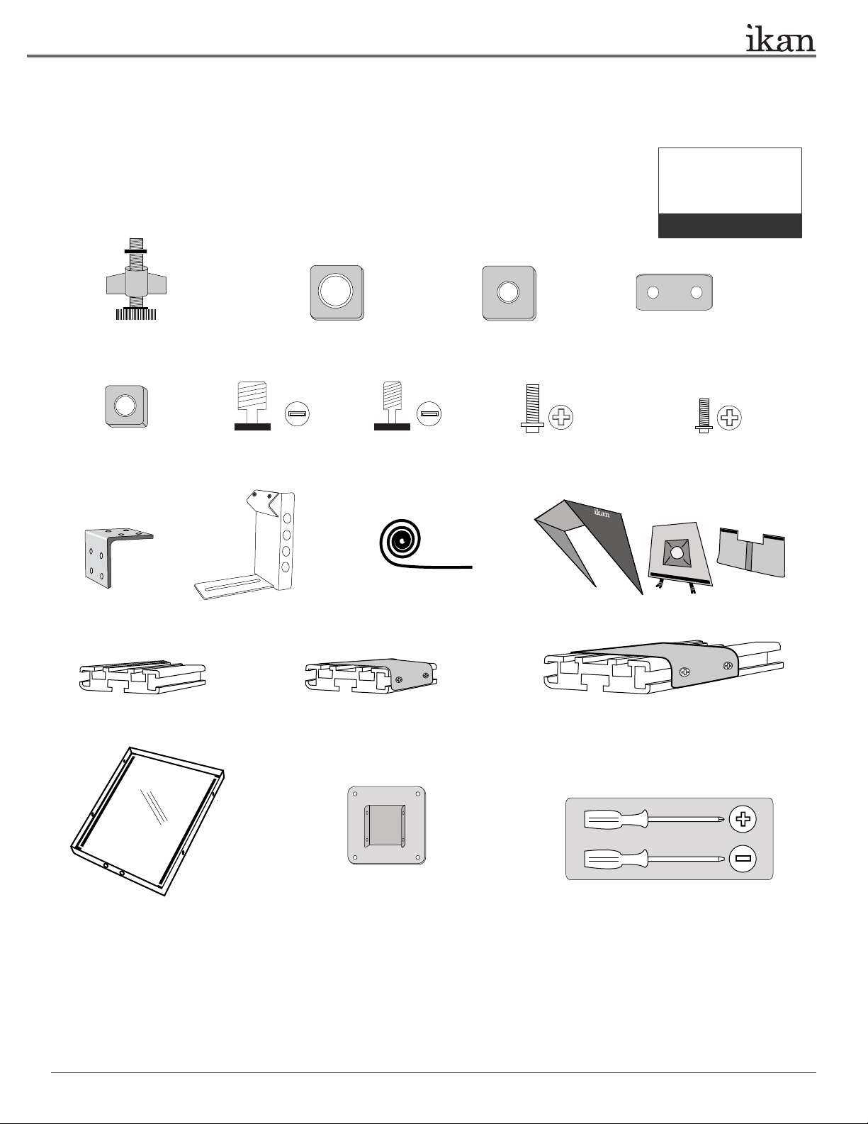
PACKAGE INCLUDES
V8000 LCD Monitor Kit
PrompterPro Software
User Guide
Teleprompter Parts:
Checked by
A
Monitor Attachment Assembly
(3-Arm Thumb Nut, Screw, T-Nut)
E
8 x T-Slot Nut
J
L-Bracket
N
F G H I
2 x 3/8-16 Screw 2 x 1/4-20 Screw
K
Coupler Bracket
B C D
2 x 3/8-16 Receiving Nut
2 x 1/4-20 Receiving Nut
20 x Phillips Head Screw(L)
L
M
Velcro (Hook)
O
P
www.ikancorp.com
8 x T-Plate
4 x Phillips Head Screw(S)
Hood (3pieces)
8” T-Slot
Q
8” T-Slot with Metal Bracket
(Optional Tripod Mount)
R
20” T-Slot with Metal Bracket
Additional Tool Needed:
Metal Frame with
30/70 Prompter Glass
3903 St oney B ro ok D r. H ou ston T X 77 063 | +1.7 13 .2 72.8 82 2 | ww w.ik an corp .c om | s up port @i ka ncor p. com | © 2009 i kan Co rp orat io n. Al l righ t rese rv ed.
100mm Mounting Bracket
(Optional Battery Mount)
** Not all parts needed for this teleprompter
assembly, depends on your camera and tripod
PT2100 8” TE L E P ROMPT E R
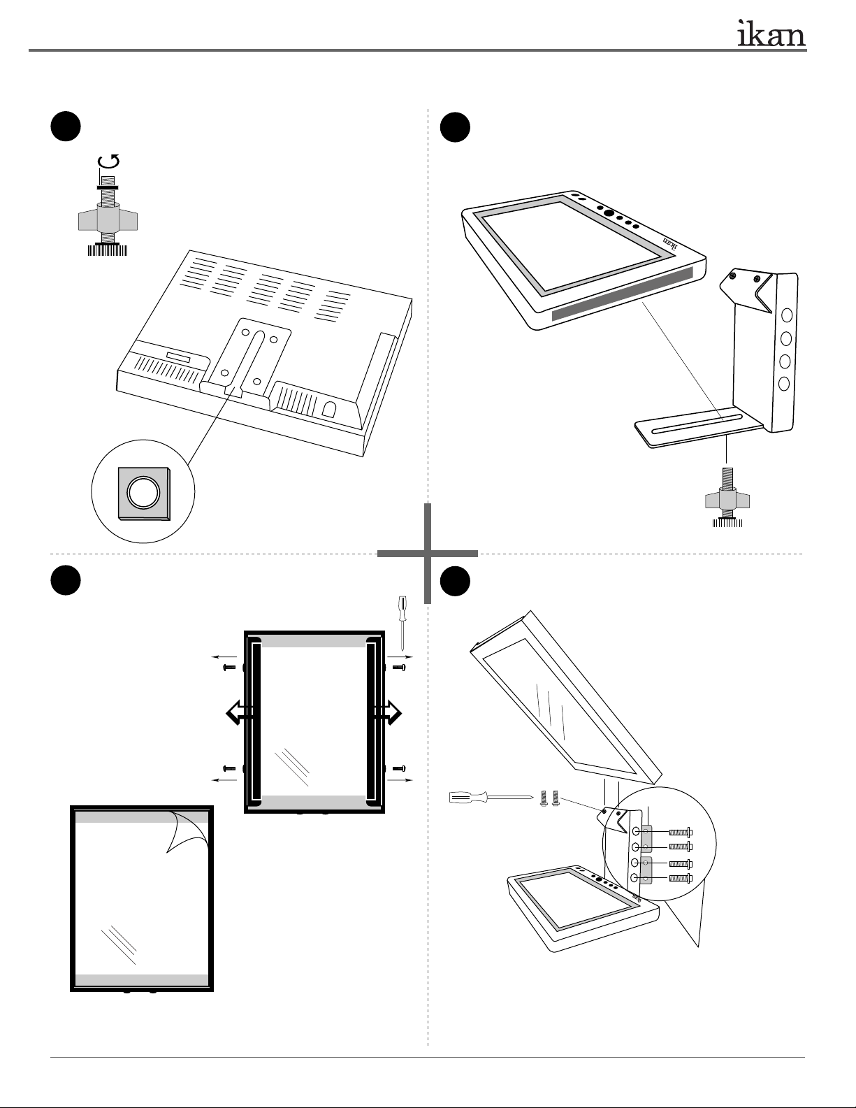
ASSEMBLY INSTRUCTION
Remove T-Nut from Part-A. Insert T-Nut in the receiving
channel of the V8000 Monitor.
1
Part-A
+
+
+
+
Place the Part-L on both sides of the V8000 monitor.
Attach V8000 monitor to Part-K. Secure the monitor
2
with the remaining Part-A.
Velcro-Hook
Part-K
Remove protective film from Part-Q.
3
> Unscrew 4 x small Phillips Head
screws
> Remove glass holding tabs on
both sides
Part-Q
> Peel the protective film
> Re-install the Teleprompter glass
back into metal frame
Attach Part-Q to Part-K.
4
Part-Q
Part-K
Part-A
> Unscrew the two Phillips Head
screws on the Part-K
> Attach Part-Q to the Part-K and
tighten with the screws
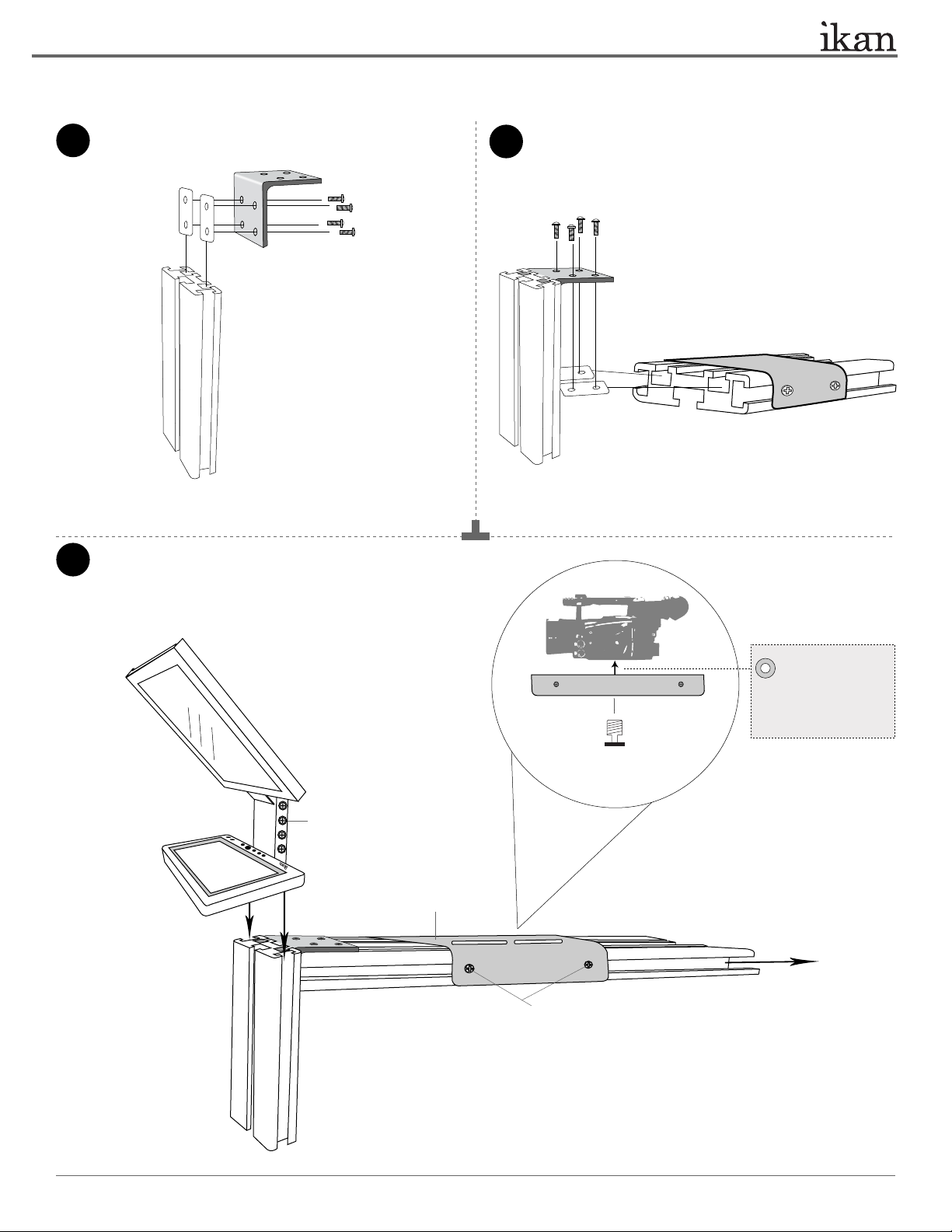
Part-D
Part-H
> Install 4 x Part-D on Part-K and
secure with 8 x Part-H (Place the
Part-D on the inner sides of Part-K)
3903 Stoney Brook Dr. Houston TX 77063 | +1.713.272.8822 | www.ikancorp.com | support@ikancorp.com | © 2009 ikan Corporation. All right reserved.
PT2100 8” TE L E P ROMPT E R
Attach Part-J to Part-N. (2 x Part-D and 4 x Part-H are needed
in this step)
5
Part-N
Attaching assembled Part-K, assembled Part-P and your camera together.
Part-J
7
Attach Part-P to the assembled parts. (2 x Part-D and 4 x Part-H
are needed in this step)
6
Part-P
> Loosen the screws to allow them
pass through the 8” T-Slot’s channels
on both sides
Metal Bracket
ikancorp.com
Washer (Not included)
ikancorp.com
Part-F or Part-G
(depends on your camera)
> Secure your camera on Metal Bracket
> Slide back in the Metal Bracket with your
camera attached, and tighten all screws
> Loosen the screws and slide out the Metal Bracket
through the channels
** Some cameras may require
an extra spacer, such as a
washer, in order to fit snugly.
3903 Stoney Brook Dr. Houston TX 77063 | +1.713.272.8822 | www.ikancorp.com | support@ikancorp.com | © 2009 ikan Corporation. All right reserved.
 Loading...