

Page 1
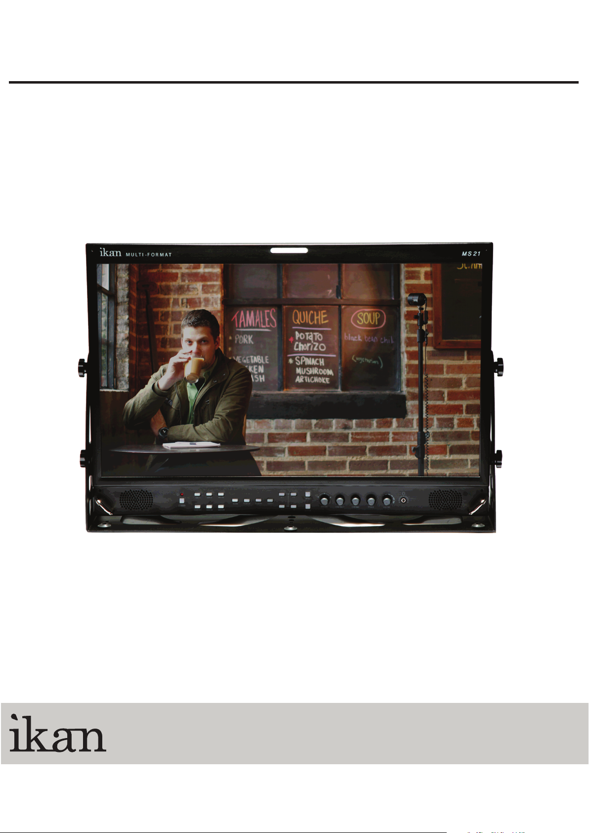
MS21
21.5" 3G-SDI Studio Monitor USER GUIDE
www.ikancorp.com
1.713.272.8822
support@ikancorp.com
© 2013 ikan Corporation. All right reserved
Page 2

Contents
Safety Instructions................................................................................................3
Front...................................................................................................................... 4
Rear.......................................................................................................................6
MENU Description................................................................................................7
VIDEO....................................................................................................................9
DISPLAY 1...........................................................................................................10
DISPLAY 2...........................................................................................................12
COLOR.................................................................................................................14
MARKER..............................................................................................................15
OSD......................................................................................................................17
AUDIO.................................................................................................................. 19
GPI....................................................................................................................... 21
SYSTEM..............................................................................................................23
USB Firmware Update........................................................................................25
External Remote Control....................................................................................26
List of Compatible Video Formats (HDMI/Composite)......................................28
List of Compatible Video Formats (SDI)............................................................29
Specifications...................................................................................................... 31
Dimensions..........................................................................................................32
Troubleshooting.................................................................................................. 33
Warranty Information..........................................................................................35
Modification of Product.......................................................................................35
Caution on Menu Operation................................................................................35
Caution for Monitor Placement...........................................................................35
2
Page 3

Safety Instructions
• To help avoid damaging your monitor, connect only one power (AC or DC) in
operation.
• Rough handling of product may cause physical damage or malfunction.
• Never insert anything metallic into the monitor openings. Doing so may create
the danger of electric shock.
• To avoid electric shock, never touch the inside of the monitor. Only a qualified
should open the monitor’s case.
• Openings in the monitor cabinet are provided for ventilation. To prevent
overheating, these openings should not be blocked or covered.
• Put your monitor in a location with low humidity and a minimum of dust. Avoid
places like damp basement or dusty hallways.
• Place the monitor on a solid surface and treat it carefully. The screen is made of
glass and can be damaged if dropped or sharply hit.
• Do not attempt to remove the back cover, as you will be exposed to a shock
hazard. The back cover should only be removed by qualified service personnel.
• Unplug the monitor power before you connect external devices to the monitor.
• If your monitor does not operate normally, or if there are any unusual sounds or
smells coning from it, unplug it immediately and contact us.
• Please do not disassemble the monitor. No service will be provided in that case.
• Displaying fixed picture for a long time may cause an afterimage or dead spots.
To recover LCD pixels, display whole white picture on screen for a n hour or
two and pixels will be recovered.
• No service will be provided for user’s own color calibration.
3
Page 4

Front
Standby (Power)
Input Switcher (SDI 1, SDI 2, HDMI/DVI)
Analog
Switch analog input in the order of CVBS1 -> CVBS2 -> CVBS3 -> SVIDEO ->
YPbPr -> RGB -> VGA.
WF/VS
Waveform / Vectorscope display selection button.
Marker On/Off
Frame line generation button.
Scan
Switch scan mode among Zero Scan, Under Scan, Over Scan, Pixel to Pixel in HD
resolution. Zero Scan, Under Scan, Over Scan, Pixel to Pixel in SD resolution.
H/V Delay
Displays ancillary data by moving screen position.
R/G/B Gray
Switch for Red/Green/Blue/Gray only.
Aspect
Adjust aspect ratio in the order of 4:3, 16:9, Fill, Native.
Function Keys
User-assigned function keys.
4
Page 5

Menu
Enter
Knob for Adjustment or Enter
Knob used to adjust Brightness / Contrast / Chroma / Phase or Enter button.
Headphone Jack
5
Page 6
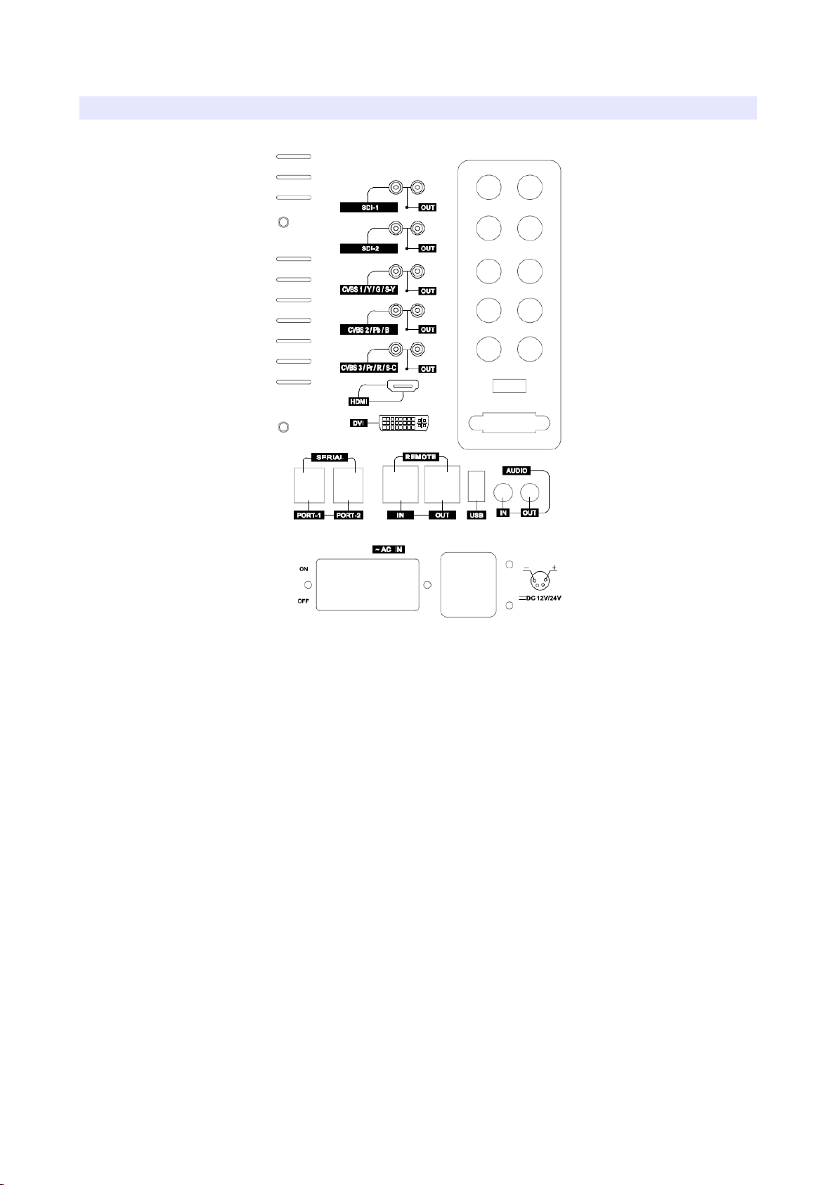
Rear
AC Input
Please check Power Cord, Power Voltage, Supply power for power input are
suitable for the standard before use.
Please do not mix AC power and DC power as it may cause the defects or fire.
DC Input
For DC power supply. Check the DC Input voltage. In case of using the Battery
power, DC 11 ~ 27V is usable.
Update Port
The Serial communication terminal that for changing the operating
program(Firmware) of the body or controlling the monitor.
Remote Ethernet Port
External control via PC is able with this port by using 'Wall Control Program'.
Firmware is also updatable through this port.
6
Page 7

USB Port
USB Firmware Update Port.
MENU Description
General Cautions for OSD menu or Display
The menu may not be displayed even when user pressed Menu button if there's No
Signal, or in unclear signal status.
The menu selection may be saved for each input signal mode, so sometimes user
should do menu selection again.
7
Page 8
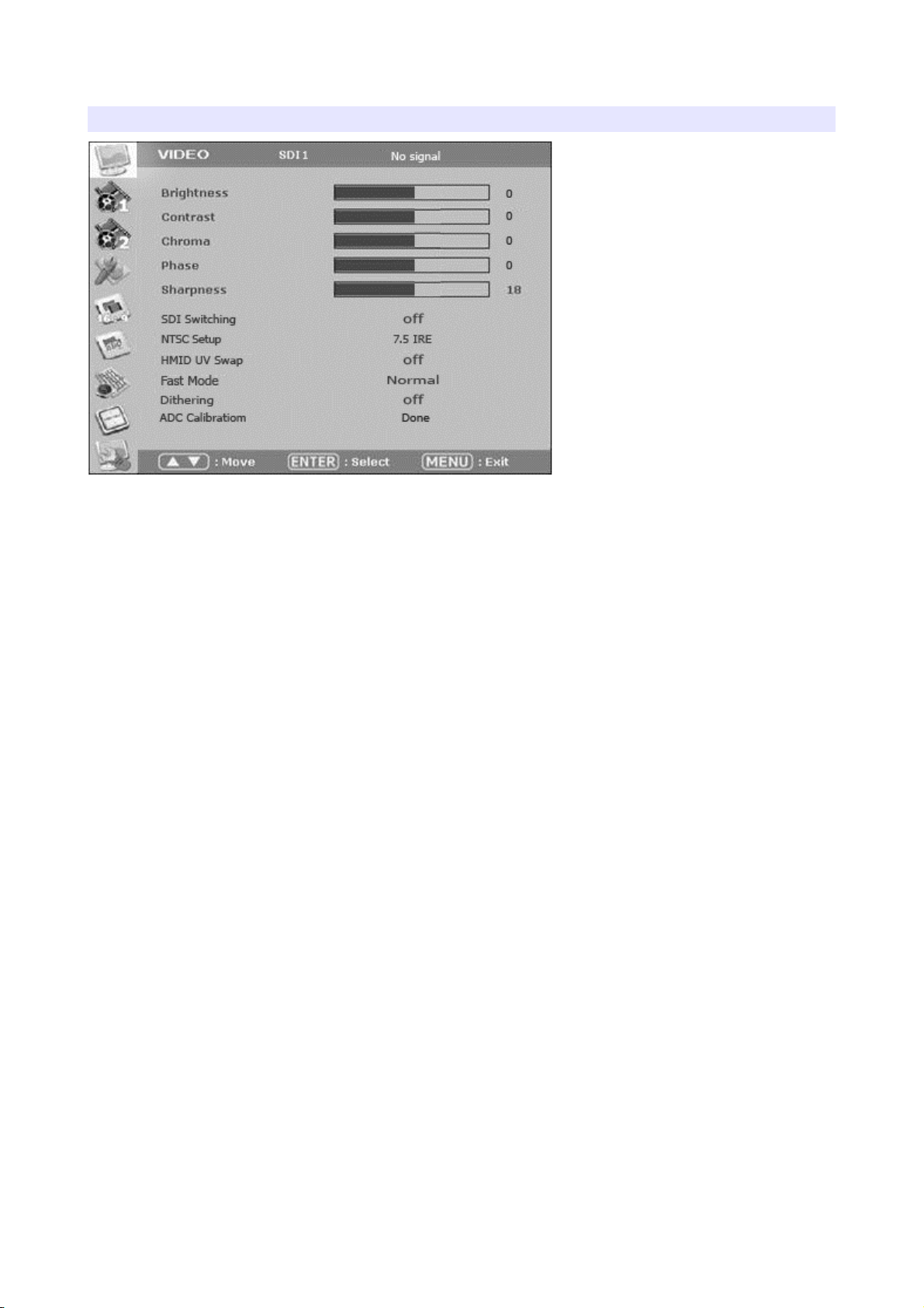
VIDEO
Brightness, Contrast, Chroma, Phase, Sharpness
Adjust color representation values.
SDI Switching
Normal : Use Normal in general condition but the screen might be blinking on
screen change when you use Matrix or Routing Switcher.
Fast : Use Fast to minimize blinking on screen change.
NTSC Setup
Select IRE among 0 or 7.5 (Default)
HDMI UV Swap
Sometimes color might be swapped on some HDMI input such as PC RGB. Turn
this mode on to return to correct color.
Fast Mode
Use this mode to minimize afterimage on very fast video.
Dithering
Turn this mode on to view motion pictures smoothely when the source has low
quality.
ADC Calibration
On CVBS input, turn this mode on when the color value is upside down. Normally it
is not needed to be turned on.
8
Page 9

DISPLAY 1
Aspect
Set the aspect ratio of the screen. 16:9, 4:3, Native(Original) are selectable. This
selection is ignored on 1080i, 1080p, 720p.
1:1 Scan
On SD signals(Not HD), Set this on to display picture in 1:1 pixel mapping.
AFD
Turn this mode on to adjust aspect ratio with the ratio value in the source signal.
Waveform Display
Select waveform display mode. Choose Normal to analyze whole screen, choose
Line Select to analyze a specific line of the screen.
Waveform Line Select
Select the line when you select Line Select mode for Waveform display.
Waveform Select
Select waveform line to display among Y, Cb, Cr.
Waveform Color Mode
Select waveform color mode among Single or Mix.
9
Page 10

Waveform Intensity
Adjust waveform intensity.
Waveform & Vector Size
Adjust size of Waveform & Vector.
Waveform & Vector Blend
Adjust transparency value of Waveform & Vector.
False Color
Turn False Color mode on to check exposure levels of the picture.
10
Page 11

DISPLAY 2
Exposure Range Check (Video Range Check)
Checks Y, C level and displays over-exposed or under-exposed area on screen.
The base value can be Y, Cb, or Cr.
Y Range Max / Min
Set Y range value for range check.
C Range Max / Min
Set C range value for range check.
Blink Color
The filled area color by range check can be either Black, Blue, Green or Red.
Blink Time
Set blinking time of the area between 1 to 5 seconds.
Focus Assist Display
Turns on Focus Assist mode. This mode can be set also by pressing Focus Assist
button in front.
Focus Assist Level
The sensitivity of the focus assist function can be set between 0 to 48.
11
Page 12

Focus Assist Color
Set brush color of focus assist mode among Blue, Green, and Red.
12
Page 13

COLOR
Color Temperature
Select color temperature among 3200K, 5400K, 6500K, 9300K or USER. (Gain and
Offset menu are displayed on USER temperature only)
Red/Green/Blue Gain (USER mode only)
R,G,B gains are adjustable on User mode.
Red/Green/Blue Offset (USER mode only)
R,G,B offsets are adjustable on User mode.
13
Page 14

MARKER
Marker Ratio
Select one of preset markers or user marker. To display marker, press Marker
button in front of the monitor.
Center Marker
Set preference to display center marker or not.
Safety Area 16:9
Adjust size of the safety area when marker displayed on 16:9 screen.
Safety Area 4:3
Adjust size of the safety area when marker displayed on 4:3 screen.
Marker Color
Select marker’s color among White, Red, Green, Blue, Gray and Black.
Marker Mat
Set how to display outside of the safety area. Normal, Half(Gray), Black are
selectable.
Marker Thickness
Set marker thickness between 1 to 10.
14
Page 15

User Marker H1 / User Marker H2 / User Marker V1 / User Marker V2
Set user marker’s position. H1 for left, H2 for right, V1 for top, V2 for bottom. The
positions are saved as the selected marker name such as USER1.
15
Page 16

OSD
Timecode Display On/Off
Timecode Position
Set the position of timecode.
OSD Display Time
Set menu display time (seconds)
MENU Position
Set menu position among Left Top, Right Top, Left Bottom, Right Bottom and
Center.
V-Chip
SD-SDI, Composite signal might contain V-Chip data. Turn this mode on to display
V-Chip information on screen.
Closed Caption
Select one of 608 Line 21, 608 VANC, 608 Transcoded, 708 to display Closed
Captions. In special condition such as menu display status, captions are not
displayed.
CC708 Service
Select one of CC service as your preference.
16
Page 17

Service 1: general captions.
Service 2: translated captions.
Service 3,4: not assigned.
CC608 StartLine
Display line of captions are selectable by user. (e.g. 13)
Internal Pattern
Show internal test pattern such as color bars. Turn this mode off to display general
pictures from input port.
UMD Display
Display UMD status. The screen aspect ratio will turn to 16:9 on this mode.
UMD Color
Set UMD color.
UMD Edit
Edit UMD text.
17
Page 18

AUDIO
Embedded Audio Left
Select audio channel for left (Ch 1 ~ 15)
Embedded Audio Right
Select audio channel for right (Ch 2 ~ 16)
Audio Level Meter
Turns on/off audio level meters.
Level Meter Size
Select the size of the meters : Small or Large.
Level Meter Position
Select the position of the meters : Upper or Lower.
Level Meter Direction
Select Level Meter orientation among Horizontal or Vertical.
Speaker Source
Select the speaker output among Auto / SDI / Line In. For HDMI, use Auto mode.
Speaker Volume
Set volume of speaker.
18
Page 19

GPI
GPI Control
Turns on/off external monitor control function.
GPI Port 1,2,3,4,5,6
Assigns each GPI port’s function. (e.g. SDI 1 input, HDMI input, Tally Red) See
EXTERNAL REMOTE CONTROLLING section for details.
Remote ID Number
Assigns the ID for the monitor to control through serial port. 0 to 99 can be
assigned.
Serial Remote
Turns serial remote function on. All front buttons are locked on this mode. To exit
from this mode, press and hold Menu button for 3 seconds.
19
Page 20

SYSTEM
Function 1,2,3,4
Assigns a function to each function button. See FRONT section for detail.
Backlight
Set the backlight intensity from 0 to 40. An LCD panel requires more than 30
minutes to be settled to a new backlight value.
Front Button LED
Set front LEDs on/off status.
Font Button Lock
Locks front buttons not to work. Press and hold Menu button for 3 seconds to exit
from this mode.
Update Firmware
Turns update mode on. Select Serial or USB port for update. After firmware
update, the monitor should be turned off/turned on, and Factory Default should be
loaded before use.
Setup Load
Load monitor settings from Factory Default, User 1/2/3/4.
Setup Save
Save current monitor setting to use later. 4 settings can be saved.
20
Page 21

Firmware Version
This version number is required when you request for service.
Operating Time
This indicates total hours that the monitor operated.
21
Page 22

Page 23

External Remote Control
Connecting GPI Port(RJ-45)
Update Port (RJ-11)
1
2
3
4
5
6
Update (RJ-11)
Update Terminal Assignment
1 PIN NC 4 PIN GND
2 PIN RX+ 5 PIN TX+
3 PIN RX- 6 PIN TX-
* Turn power off first and connect update cable when you update monitor
firmware.
Remote Control / GPI Port Pin Assignments
1
2
3
4
5
6
7
8
Remote (RJ-45)
Remote PIN Assignment
1 PIN GPI Port 1 5 PIN GPI Port 5
2 PIN GPI Port 2 6 PIN GPI Port 6
3 PIN GPI Port 3 7 PIN
GPI Port 7(FIXED)
(TALLY OUT)
4 PIN GPI Port 4 8 PIN COMMON(GND)
Each pin's functionality can be assigned on OSD System Menu, GPI Control section.
23
Page 24

Assignable functions are listed below.
Function Name Description
SDI-1 Input
Switches the input to SDI-1
SDI-2 Input
Switches the input to SDI-2
HDMI Input
Switches the input to HDMI
YPbPr Input
Switches the input to YPbPr
CVBS-1 Input
Switches the input to CVBS-1
CVBS-2 Input
Switches the input to CVBS-2
CVBS-3 Input
Switches the input to CVBS-3
KEY-UP ▲
CURSOR UP on Menu Control.
KEY-DOWN ▼
CURSOR DOWN on Menu Control.
KEY- MENU
Menu On/Off
KEY-ENTER
Enter Button
Aspect
Aspect On/Off
1:1 Scan On/Off
1:1 SCAN Function On/Off
H/V Delay On/Off
H/V Delay Function On/Off
TC Display On/Off
TC Display On/Off
ALM Display On/Off
Audio Level Meters Display On/Off
Freeze On/Off
Freeze Frame On/Off
Front Button LED On/Off
Front Button LED On/Off.
Tally Red On/Off
Tally Red LED On/Off
Tally Green On/Off
Tally Green LED On/Off
24
Page 25

List of Compatible Video Formats (HDMI/Composite)
NO
Signal Input
Formats
INPUT
Composite
SD-RGB
HD-YPbPr
HDMI
1 NTSC O O
2 PAL O O
3 720*576/50i X O
4 720*480/59.94i X O
5 720*480/60i X O
6 720*576/50p
X
O
7 720*480/59.94p
X
O
6 720*480/60p
X
O
8 1280*720/23.98p
X
O
9 1280*720/24p
X
O
10 1280*720/25p
X
O
11 1280*720/29.97p
X
O
12 1280*720/30p
X
O
13 1280*720/50p
X
O
14 1280*720/59.94p
X
O
15 1280*720/60p
X
O
16 1920*1080/50i
X
O
17 1920*1080/59.94i
X
O
18 1920*1080/60i
X
O
19 1920*1080/23.98p
X
O
20 1920*1080/24p
X
O
21 1920*1080/25p
X
O
22 1920*1080/29.97p
X
O
23 1920*1080/30p
X
O
24 1920*1080/50p
X
O
25 1920*1080/59.94p
X
O
26 1920*1080/60p
X
O
25
Page 26

List of Compatible Video Formats (SDI)
NO
Input Signal
Formats
Composite/
S-Video
Component
SDI
DVI
YPbPr RGB
1 NTSC
√
- - -
-
2 PAL
√
- - -
-
3 525/60i (SD)
-
√ √ √
-
4 625/50i (SD)
-
√ √ √
-
5 720*480/59.94p
-
√
- -
√
6 720*576/50p
-
√
- -
√
7 1280*720/23.98p
- - - - -
8 1280*720/24p
- - - - -
9 1280*720/50p
-
√
-
√ √
10 1280*720/59.94p
-
√
-
√ √
11 1280*720/60p
-
√
-
√ √
12 1920*1035/59.94i
-
√
-
√ √
13 1920*1035/60i
-
√
-
√ √
14 1920*1080/50i
-
√
-
√ √
15 1920*1080/59.94i
-
√
-
√ √
16 1920*1080/60i
-
√
-
√ √
17 1920*1080/23.98p
-
√
-
√
-
18
1920*1080/23.98psf
-
√
-
√
-
19 1920*1080/24p
-
√
-
√
-
20 1920*1080/24psf
-
√
-
√
-
21 1920*1080/25p
-
√
-
√ √
22 1920*1080/25psf
- - - - -
23 1920*1080/29.97p
-
√
-
√ √
24 1920*1080/29.97psf
- - - - -
25 1920*1080/30p
-
√
-
√ √
26 1920*1080/30psf
- - - - -
27
1920*1080/50p
-
√
- -
√
28
1920*1080/59.94p
-
√
- -
√
29
1920*1080/60p
-
√
- -
√
30
2048*1080/23.98p
- - -
√
-
31
2048*1080/23.98psf
- - -
√
-
32
2048*1080/24p
- - -
√
-
33
2048*1080/24psf
- - -
√
-
26
Page 27

Specifications
BSM-182 i BSM-212 i BSM-242 i
Input
2 x BNC HD/SD-SDI, 1.485G/270M
3 x BNC Analog(YPbPr/CVBS/S-Video/RGB)
1 x HDMI HDMI (with HDCP v.1.1), 19pin Female
1 x DVI DVI-I, 24pin, Female
Output
3 x BNC Analog(YPbPr/CVBS/S-Video/RGB)
2 x BNC HD/SD-SDI, 1.485G/270M
I/O Port
1 x Phone Jack In Line In(Stereo)
2 x Phone Jack Out Line Out(Stereo), H/P Out(Front, Stereo)
2 x Speaker Out 2W+2W, Stereo
LCD
Size
18.5” 21.5” 24”
Resolution
1366 * 768 1920 x 1080 1920 x 1080
Pixel Pitch
0.3*0.3 mm 0.24825mm 0.27675mm
Color
16.7M(6bit+Hi-FRC) 16.7M(8bit) 16.7M(8bit)
Viewing Angle(deg)
170(H), 160(V) 178(H), 178(V) 178(H), 178(V)
Luminance of White
250 cd/m² 250 cd/m² 250 cd/m²
Contrast
1000 : 1 3000 : 1 3000 : 1
Display Area (H X V)
409.8 x 230.4 mm (16.1 x
9.0 inches)
476.64 x 268.11 (mm) 531.36 x 298.89 (mm)
Back Light
LED LED LED
Power Requirements
DC 12V/24V, AC100230V(50/60Hz)
DC 12V/24V, AC100230V(50/60Hz)
AC(100-230V, 50/60Hz)
Power Consumption
47W 51W 59W
Operating Temperature
0°C ~ 40°C
Operating Humidity
20% ~ 80% RH
Dimension(W*H*D) w/o Box&Stand
438.4x308.8x58.5mm(17.
2x12.1x2.3inches)
503.6x348.0x59.2mm(19
.8 x 13.7 x 2.3 inches)
563.6x376.1x60.6mm(2
2.1 x 14.8 x 2.3 inches)
Accessory • Power Cable • DVI to VGA Gender • Manual • Cleaner
Option
•Rack Mount kit
•Sunhood
•Carrying Case •V-
Moun
•Anton Battery •Protect
•Rack Mount Kit
•Handle
• Protect •V-Mount
• Rack Mount Kit
•Handle
27
Page 28

Dimensions
BSM-182i (WxHxD)
438.4 x 310.8 x 66.4mm
(17.2 x 12.2 x 2.6 inches)
BSM-212i (WxHxD)
505.6 x348.0 x 59.2mm
(19.9 x 13.7 x 2.3 inches)
BSM-242i (WxHxD)
553.4 x 403.5 x 62.5 mm
(21.7 x 15.8 x 2.4 inches)
28
Page 29

www.ikancorp.com
CONDITIONS OF WARRANTY SERVICE
• Free service for one year from the day of purchase if the problem is caused by manufacturing errors.
• The components and maintenance service fee will be charged if the warranty period has expired.
Free Service will not be Provided in the Following Situations: (* Even if the product is still within the warranty period.)
• Damage caused by abuse or misuse, dismantling, or changes to the product not made by the company.
• Damage caused by natural disaster, abnormal voltage, and environmental factors etc.
 Loading...