

Page 1

Artisan Technology Group is your source for quality
new and certied-used/pre-owned equipment
• FAST SHIPPING AND
DELIVERY
• TENS OF THOUSANDS OF
IN-STOCK ITEMS
• EQUIPMENT DEMOS
• HUNDREDS OF
MANUFACTURERS
SUPPORTED
• LEASING/MONTHLY
RENTALS
• ITAR CERTIFIED
SECURE ASSET SOLUTIONS
SERVICE CENTER REPAIRS
Experienced engineers and technicians on staff
at our full-service, in-house repair center
Instra
Remotely inspect equipment before purchasing with
our interactive website at www.instraview.com
Contact us: (888) 88-SOURCE | sales@artisantg.com | www.artisantg.com
SM
REMOTE INSPECTION
View
WE BUY USED EQUIPMENT
Sell your excess, underutilized, and idle used equipment
We also offer credit for buy-backs and trade-ins
www.artisantg.com/WeBuyEquipment
LOOKING FOR MORE INFORMATION?
Visit us on the web at www.artisantg.com for more
information on price quotations, drivers, technical
specications, manuals, and documentation
Page 2
30 308 00 c
IKAIKA
®®
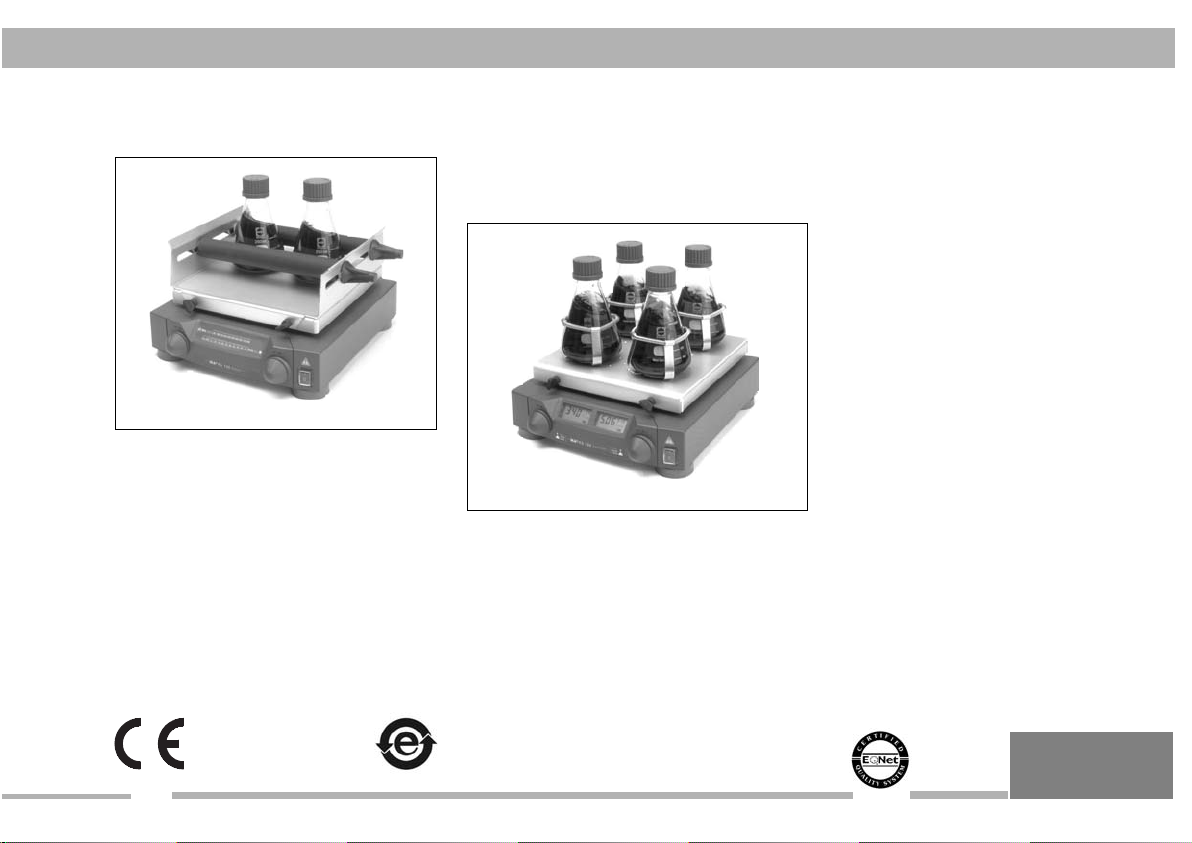
IKA KS 130 basic
KS 130 basic
IKA KS 130 control
KS 130 control
IKA®WERKE
BETRIEBSANLEITUNG
DE
3
032007
OPERATING INSTRUCTIONS
MODE D’EMPLOI
Reg.-No. 4343-01
Artisan Technology Group - Quality Instrumentation ... Guaranteed | (888) 88-SOURCE | www.artisantg.com
EN
FR
19
35
Page 3

CE-KONFORMITÄTSERKLÄRUNG DE
Wir erklären in alleiniger Verantwortung, daß dieses Produkt den Bestimmungen
der Richtlini-en 89/336/EG und 73/023/EG entspricht und mit den folgenden
Normen und norminativen Dokumenten übereinstimmt: DIN EN IEC 61010-1 und
DIN EN IEC 61326-1.
CE-DECLARATION OF CONFORMITY EN
We declare under our sole responsibility that this product corrosponds to the regulations 89/336EEC and 73/023EEC and conforms with the standards or standardized documents DIN EN IEC 61010-1 and DIN EN IEC 61326-1.
DÉCLARATION DE CONFORMITÉ CE FR
Nous déclarons sous notre propre responsabilité que se produit est conforme aux
réglementations 89/336CEE et 73/023CEE et en conformité avec les normes ou
documents normalisés suivant DIN EN IEC 61010-1 et DIN EN IEC 61326-1.
Warranty
You have purchased an laboratory machine which meets the highest engineering and quality standards.
In accordance with guarantee conditions, the guarantee period is
24 months. For claims under the guarantee please contact your
local dealer. You may also send the machine direct to our works,
enclosing the delivery invoice and giving reasons for the claim.
You will be liable for freight costs.
The warranty does not cover wearing parts, nor does it apply to
faults resulting from improper use or insufficient care and maintenance contrary to the instructions in this operating manual.
If you require servicing, return the appliance in its original packaging. Storage packaging is not sufficient. Please also use suitable
transport packaging.
Gewährleistung
Sie haben ein Laborgerät erworben, das in Technik und Qualität
höchsten Ansprüchen gerecht wird.
Entsprechend den Verkaufs- und Lieferbedingungen beträgt die
Garantiezeit 24 Monate. Im Garantiefall wenden Sie sich bitte an
Ihren Fachhändler. Sie können aber auch das Gerät unter
Beifügung der Lieferrechnung und Nennung der Reklamationsgründe direkt an unser Werk senden. Frachtkosten gehen zu Ihren
Lasten.
Die Garantie erstreckt sich nicht auf Verschleißteile und gilt nicht
für Fehler, die auf unsachgemäße Handhabung und unzureichende Pflege und Wartung, entgegen den Anweisungen in dieser
Betriebsanleitung, zurückzuführen sind.
Senden Sie im Servicefall das Gerät in der Originalverpackung
zurück. Lagerverpackungen sind für den Rückversand nicht ausreichend. Verwenden Sie zusätzlich eine geeignete Transportverpackung.
2
Artisan Technology Group - Quality Instrumentation ... Guaranteed | (888) 88-SOURCE | www.artisantg.com
Garantie
Vous avez fait l’acquisition d’un appareil de laboratoire , qui répond
aux exigences les plus élevées de technique et de qualité.
Conformément aux conditions de garantie, la durée de garantie
s’élève à 24 mois. En cas de recours en garantie, veuillez vous
adresser à votre fournisseur spécialisé. Vous pouvez également
envoyer directement l’appareil à notre usine en joignant votre facture et l’exposé des motifs de réclamation. Les frais d’expédition
sont à votre charge.
La garantie ne s’étend pas aux pièces d’usure et n’est pas valable
en cas de défauts dus à une utilisation non conforme et un soin et
un entretien insuffisants, allant à l’encontre des recommandations
du présent mode d’emploi.
En cas de retour au service après vente, renvoyez l’appareil dans
son emballage d’origine. Les emballages de stockage ne sont pas
suffisants pour le renvoi. Utilisez un emballage de transport supplémentaire adapté.
032007
Page 4
032007
Inhaltsverzeichnis
Seite
Garantie 2
Sicherheitshinweise 3
Bestimmungsgemäßer Gebrauch 4
Auspacken 5
Wissenswertes 5
Inbetriebnahme 5
Einschalten 6
Anzeige 6
Betriebsarten 7
Einstellen der Schüttelzeit 10
Einstellen der Drehzahl 11
Aufsätze 12
Auflagegewicht (Zuladung) 12
Fehlermeldungen (Error codes) 13
Schnittstelle und Ausgänge 14
Verbindungsmöglichkeiten Laborgerät - PC 16
Motorschutz / Sicherheitseinrichtungen 17
Wartung und Reinigung 17
Zubehör 18
Technische Daten 18
Ersatzteilliste / Ersatzteilbild KS 130 b 52/53
Ersatzteilliste / Ersatzteilbild KS 130 c 54/55
Sicherheitshinweise
Der einwandfreie und gefahrlose Betrieb des Gerätes setzt voraus, dass jeder Anwender die Betriebsanleitung gelesen hat und
die enthaltenen Sicherheitshinweise beachtet werden. Bewahren
Sie diese Betriebsanleitung sorgfältig und für jedermann zugänglich auf.
Der Umgang mit diesem Gerät sollte nur durch entsprechend
Artisan Technology Group - Quality Instrumentation ... Guaranteed | (888) 88-SOURCE | www.artisantg.com
geschultes Personal erfolgen, welches das Gerät kennt und
berechtigt ist, Arbeiten in diesem Bereich durchzuführen.
Das Gerät darf - auch im Reparaturfall - nur von einer Fachkraft
geöffnet werden. Vor dem Öffnen ist der Netzstecker zu ziehen.
Spannungsführende Teile im Inneren des Gerätes können auch
längere Zeit nach Ziehen des Netzsteckers noch unter Spannung
stehen.
sein, damit zum Beispiel das Eindringen von Fremdkörpern,
Flüssigkeiten, etc. verhindert wird.
Der Anwender muss beim Arbeiten mit dem Gerät seine persönliche Schutzausrüstung, entsprechend der Gefahrenklasse des zu
mischenden Mediums wählen und tragen. Bei defekter oder unangemessener Schutzausrüstung
kann der Anwender durch
Spritzen von Flüssigkeiten,
Herausschleudern von Teilen,
oder Hereinziehen am
Schütteltisch, bzw. Aufsatz
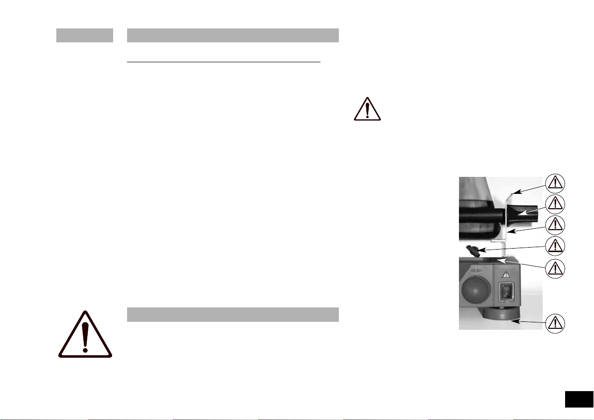
gefährdet werden. Es dürfen
keine bewegten Teile berührt
werden (Quetsch-, Stoß- und
Schnittgefahr, siehe Bild 1:
Gefahrenstellen). Achten Sie
darauf, dass Körperteile, Haare
oder Kleidungsstücke nicht von
bewegten Teilen erfasst werden können.
Beachten Sie einschlägige
Sicherheitshinweise und Richtlinien, sowie Arbeitsschutz- und
Unfallverhütungsvorschriften
für den Einsatz im Labor.
Beim Transport des Gerätes ist das hohe Eigengewicht zu berücksichtigen. Es ist darauf zu achten, dass beim Abstellen des Gerätes
die Finger nicht gequetscht werden.
ACHTUNG! Abdeckungen, bzw. Teile, die ohne
Hilfsmittel vom Gerät entfernt werden können, müssen
zum sicheren Betrieb wieder am Gerät angebracht
Bild 1 Gefahrenstellen
3
Page 5

Das Gerät darf nur auf einem ebenen, stabilen und rutschfesten
Unterbau aufgestellt werden.
Achten Sie vor Inbetriebnahme darauf, dass der Drehknopf zur
Einstellung der Schüttelfrequenz auf Linksanschlag steht, da das
Gerät mit der zuletzt eingestellten Schüttelfrequenz zu laufen
beginnt. Richten Sie Ihre Aufmerksamkeit beim Einstellen der
Schüttelfrequenz auf die auf dem Schütteltisch befindlichen
Gefäße. Ein mögliches Herausspritzen des zu schüttelnden
Mediums aus den Probegefäßen kann dadurch vermieden werden.
Die für den Schüttelvorgang verwendeten Zubehörteile und aufgestellten Gefäße müssen gut befestigt werden.
Nicht richtig befestigte Schüttelgefäße können beschädigt oder herausgeschleudert werden und Personen gefährden. Die Befestigung
der zu schüttelnden Gefäße, sowie die Befestigung der Aufsätze,
muss in regelmäßigen Abständen und vor allem vor jeder Neuinbetriebnahme kontrolliert werden.
Wird ein unruhiger Lauf des Gerätes bemerkt, muss auf jeden Fall
die Schüttelfrequenz soweit reduziert werden, bis keine
Laufunruhen mehr auftreten.
Beim Schütteln können infolge ungünstiger Beladung und
Schwerpunktlage dynamische Kräfte auftreten, die ein Wandern des
Schüttlers auf der Abstellfläche verursachen können.
kungen der Belastbarkeit bzw. des Auflagegewichtes bei hohen
Schüttelfrequenzen können dem Diagramm im Absatz „Auflagegewicht“ entnommen werden.
Nach einer Unterbrechung der Stromzufuhr während eines
Schüttelvorganges läuft das Gerät
Zusätzliche Gefährdungen für den Anwender können auftreten,
wenn beim Schüttelvorgang entzündliche Materialien verwendet
werden.
Es dürfen nur Stoffe oder Mischungen von Stoffen mit dem
Schüttler geschüttelt werden, von denen der Anwender Kenntnis
darüber hat, dass der Energieeintrag durch das Schütteln unbedenklich ist. Das gleiche gilt auch für den Energieeintrag durch
Sonneneinstrahlung während des Schüttelvorgangs.
Der Schüttler darf nicht für den Betrieb in gefährlichen
Atmosphären, zum Mischen von Gefahrstoffen und für den Betrieb
4
Artisan Technology Group - Quality Instrumentation ... Guaranteed | (888) 88-SOURCE | www.artisantg.com
nicht von selbst wieder an.
Einschrän-
unter Wasser eingesetzt werden.
Das Zubehör darf nur nach Ziehen des Netzsteckers montiert werden.
Der Schutz für den Benutzer ist nicht mehr gewährleistet, wenn das
Gerät mit Zubehör betrieben wird, welches nicht vom Hersteller
geliefert oder empfohlen wird, oder wenn das Gerät in nicht bestimmungsgemäßem Gebrauch, entgegen der Herstellervorgabe betrieben wird.
Im Servicefall muss die von IKA gewählte Kabelverlegung wieder
hergestellt werden!
Bei zu schneller Veränderung des Drehzahlsollwertes schaltet
das Gerät selbstständig ab. Vermeiden Sie Stösse und Schläge
auf den Schütteltisch.
Bereits kleine, nicht erkennbare Schäden können zur
Beschädigung der Motorlagerung führen. Sorgsame Behandlung
garatiert sicheres Arbeiten und Langlebigkeit des Gerätes.
Bestimmungsgemäßer Gebrauch
Der KS 130 basic und KS 130 control eignet sich durch
Verwendung unterschiedlicher Aufsätze zum Mischen von Flüssigkeiten in Flaschen, Kolben, Reagenzgläsern und Schalen für ein
maximales Auflagegewicht von 2 kg.
Er ist für den Einsatz in Laboratorien konzipiert. Die Bewegung des
Schütteltisches bzw. der aufgestelleten Gefäße ist kreisförmig.
Zum Bestimmungsgemäßen Gebrauch muss das Gerät auf einer
stabilen, ebenen und möglichst rutschfesten Aufstellfläche stehen. Außerdem muss darauf geachtet werden, dass sich nur in
ausreichendem Abstand Gegenstände in der Nähe des Schüttlers
befinden dürfen und diese während des Schüttelvor-ganges nicht
wandern können.
032007
Page 6
Auspacken
IKA
R
1/min1/min
m
inminTime
basicHS250
O
FF
ON
1
0515
Mot
60
30 90
2
520 30 35 454050
210120 150 180 270240 300
A
Bitte packen Sie das Gerät vorsichtig aus und achten Sie auf
Beschädigungen. Es ist wichtig, daß eventuelle Transportschäden schon beim Auspacken erkannt werden. Gegebenenfalls ist
eine sofortige Tatbestandsaufnahme erforderlich (Post, Bahn
Schnittstelle betrieben, verhält es sich wie ein Control-Gerät
ohne Reversierbetrieb.
Die verschiedenen Aufsätze sind einfach austauschbar.
Die Control-Gerätevariante ist mit einer seriellen Schnittstelle
ausgestattet, die ein Steuern des Gerätes über den PC (z.B.
Labworldsoft) ermöglicht.
oder Spedition).
Zum Lieferumfang des Gerätes gehören:
Ein KS 130 basic oder KS 130 control, vier Klemmschrauben, ein
Einmaulschlüssel, ein Netzkabel und eine Betriebsanleitung.
Inbetriebnahme
Überprüfen Sie, ob die auf dem Typenschild angegebene
Wissenswertes
Spannung mit der verfügbaren Netzspannung übereinstimmt. Die
verwendete Steckdose muß geerdet sein (Schutzleiterkontakt).
Wenn diese Bedingungen erfüllt sind, ist das Gerät nach
Mit diesem Gerät haben Sie ein qualitativ hochwertiges Produkt
erworben. Durch die Gerätekonzeption und die Formgebung ist
eine einfache Handhabung und problemloses Arbeiten gewährleistet. Die verwendeten Werkstoffe und deren genaue
Kennzeichnung ermöglichen und vereinfachen das Recycling und
die Wiederverwendung der Teile entscheidend.
Der drehzahlgeregelte Außenläufermotor ermöglicht ein stufenloses Einstellen der Drehzahl im Bereich von 0 bis 800 1/min. Die
elektronische Motorregelung hält die eingestellte Drehzahl auch
bei Zunahme des Auflagegewichtes konstant. Durch die Wärmeabgabe des Motors kann sich die Aufstellfläche für die Schüttelgefäße erwärmen.
Die Control-Gerätevariante ist mit einer Arretiereinrichtung ausgestattet. Diese ermöglicht den Schütteltisch in einer definierten
Position zu fixieren. Durch entfernen der Gummifüsse kann das
Gerät im Raum oder in einer Anlage mit der Umgebung definiert
verbunden (angeschraubt) werden. Achten Sie darauf, dass die
Einschraubtiefe von max. 5mm nicht überschritten wird.
Die Control-Gerätevariante kann auf Anfrage mit einem Reversierbetrieb (Rechts- / Linkslauf) des Schütteltisches ausgeliefert
werden. Der Reversierbetrieb kann jedoch nur über die serielle
Schnittstelle in Verbindung mit einem PC (z.B. mit labworldsoft)
genutzt werden. Wird das Gerät nicht an einer seriellen
032007
Artisan Technology Group - Quality Instrumentation ... Guaranteed | (888) 88-SOURCE | www.artisantg.com
Einstecken des Netzsteckers betriebsbereit. Andernfalls ist sicherer Betrieb nicht gewährleistet oder das Gerät kann beschädigt
werden.
Beachten Sie die in den Technischen Daten angegebenen Umgebungsbedingungen (Temperatur, Feuchte).
Beim Einschalten der Basic-Gerätevariante muß der Drehknopf
der Zeiteinstellung in der Mittelstellung stehen (nicht betätigt).
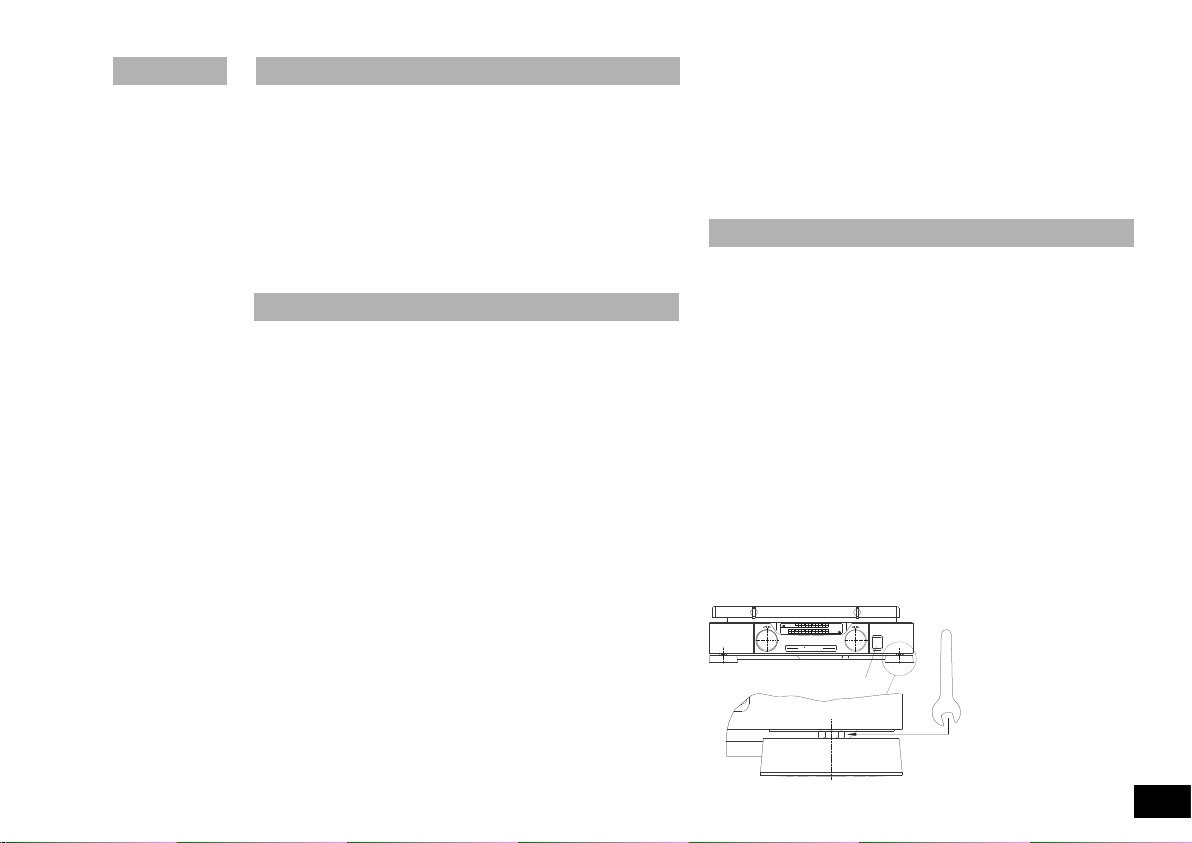
Bei unebener Aufstellfläche kann über die einstellbaren
Gerätefüße die Standsicherheit des Gerätes verbessert werden.
Drehen Sie hierzu den erforderlichen Gerätefuß mittels des mitgelieferten Einmaulschlüssels solange nach unten, bis das Gerät
sicher auf der Unter-
lage steht.
Um ein selbständiges
Lösen des Gerätefus-
ses zu verhindern, hal-
ten Sie den Fuß mit der
Hand fest und ziehen
Sie die Sechskant-
mutter entgegenge-
setzt handfest an.
5
Page 7
Einschalten
50
100 150
200
250
Mot
1/min
Time
min
300 350 400 450 500
On Off 40 45
50
3530201015525
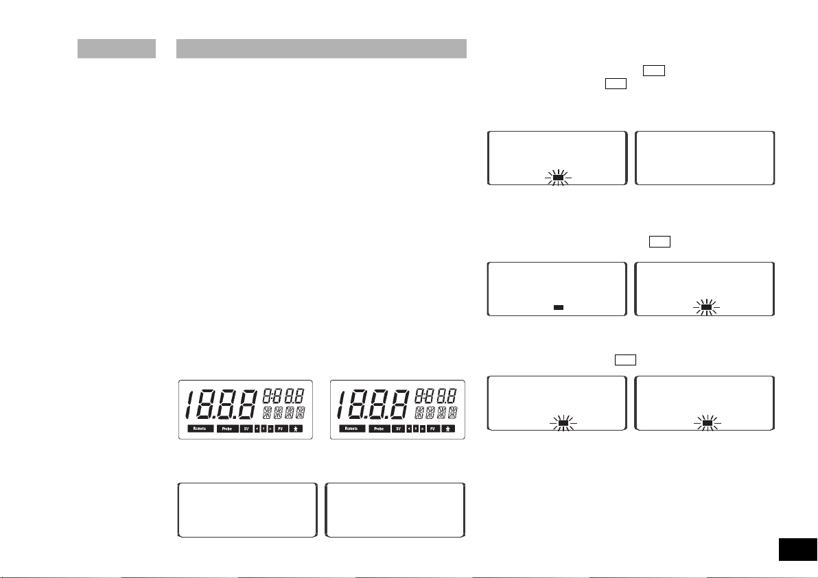
Das Gerät wird über den Wippenschalter A an der Gerätefrontseite eingeschaltet. Nach dem Einschalten des Netzschalters in
Stellung I leuchten bei der Basic-Variante alle Leuchtdioden kurzfristig, als Selbsttest in den Anzeigefenstern auf und anschließend zeigt die rote Leuchtdiode, in der LED-Zeile TIME, den
OFF-Betrieb des Gerätes an (akkustisches Signal).
Bei der Control-Variante blinken alle Anzeigeelemente der
Digitalanzeigen kurzfristig auf, wodurch die Durchführung des
Geräteselbstestes angezeigt wird. Dabei werden alle sicherheitsrelevanten Funktionen überprüft. Anschließend ist das
Gerät betriebsbereit.
Anzeige
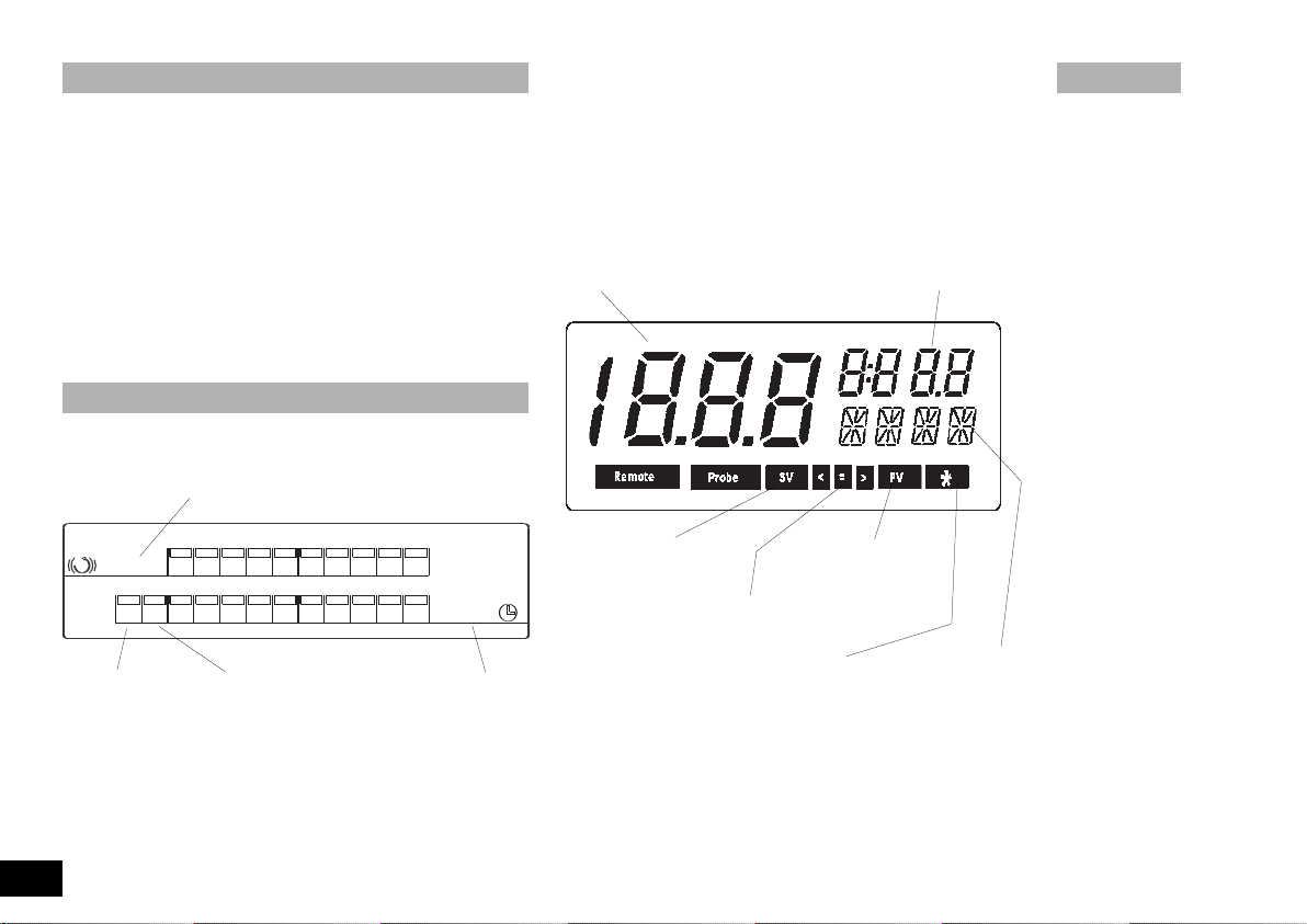
Beschreibung der LED-Anzeige des KS 130 basic
Anzeigebalken für die eingestellte Drehzahl
Zeitbetrieb: Das Gerät unterbricht nach Ablauf einer einge
stellten Zeit (max. 50 min) den Schüttelvorgang
Die für den Schüttelvorgang erforderliche Drehzahl kann vor oder
nach der Betriebsartenwahl eingestellt werden.
Ab Werk ist der KS 130 basic so eingestellt, daß nach Drücken
des Netzschalters die Funktion Schütteln (Drehzahl) und der
Zeitbetrieb ausgeschaltet ist (Off-LED leuchtet).
Beschreibung der Digitalanzeige des KS 130 control
rocesst
Sollwert
V
V
alue
Istwert
V
SSV
=
S
V
S
V
et
alue
(Sollwert)
=
=
= Arretierung
PPV
V
P
P
=
(Istwert)
Dauerbetrieb
Stillstand
Anzeigebalken für
die eingestellte Schüttelzeit
Zeitbetrieb
Die Basic-Gerätevariante kann nach Wahl im Dauer- oder
Zeitbetrieb verwendet werden. Die Einstellung erfolgt über den
rechten Drehknopf.
Dauerbetrieb: Das Gerät unterbricht den Schüttelvorgang
6
nicht (On-LED leuchtet)
Artisan Technology Group - Quality Instrumentation ... Guaranteed | (888) 88-SOURCE | www.artisantg.com
Betriebsart A: Stern aus
Betriebsart B: Stern ein
Betriebsart C: Stern blinkt
z.B. phys. Einheit
Betriebsart,
Fehlermeldung
032007
Page 8
Betriebsarten
I30
KS A
230
SAFE
SV
I
min
/
A
230
SAFE
minn
i
358
:
SV
SV
OK
I30
I
min
/
SV
minn
i
358
:
SV
Einstellen der Betriebsart (nur Control-Variante)
Die Control-Gerätevariante kann in den nachfolgend beschriebe-
nen Betriebsarten betrieben werden:
Betriebsart A:
Ab Werk ist der KS 130 control in die Betriebsart A geschaltet.
Nach dem Einschalten des Gerätes mit dem Netzschalter
(Wippschalter) sind die Funktionen Schütteln und Zeitablauf ausgeschaltet. Die eingestellten Sollwerte sind gespeichert und
werden digital angezeigt. Sie werden beim Einschalten der
jeweiligen Funktion übernommen. Die eingestellten Sollwerte
können verändert werden. Nach einer Netzunterbrechung müssen beide Funktionen neu gestartet werden. Die Drehzahlobergrenze kann nur in der Betriebsart
werden. Die Betriebsart A erkennt man daran, daß kein Stern in
der Display Menüleiste der Zeiteinstellung angezeigt wird.
Nach einer Netzunterbrechung läuft das Gerät in der Betriebsart
A nicht von selbst wieder an.
Nach der Wahl der Betriebsart und dem Einschalten des Gerätes
wird der folgende Ablauf auf dem Display angezeigt.
a.) Alle Anzeigeelemente der Digitalanzeigen sind ca. 2 sec aktiviert.
A eingestellt bzw. verändert
c.) Danach wird im linken Display die eingestellte (bzw. abge-
speicherte) Drehzahlobergrenze des Schüttlers mit SAFE, der
Einheit 1/min und dem blinkenden SV ca. 2 sec lang angezeigt.
Solange die Anzeige mit SV blinkt, kann durch gleichzeitiges
Drücken und Drehen des linken Drehknopfes die Drehzahlobergrenze verändert werden.
d.) Ist die Drehzahlobergrenze festgelegt, wechselt in der linken
Anzeige die Einheit 1/min in OK. In der rechten Anzeige wird der
neu eingestellte oder abgespeicherte Zeitsollwert (z.B. 3:58) mit
der Angabe h min und blinkendem SV angezeigt.
e.) Daraufhin wird in der linken Anzeige der abgespeicherte oder
neu eingestellte Drehzahlsollwert (z.B.
1/min und dem blinkenden SV angezeigt.
130) mit der Einheit
032007
b.) Anzeige der Gerätetype (linkes Display) und Betriebsart (rechtes Display) ca. 2 sec.
Artisan Technology Group - Quality Instrumentation ... Guaranteed | (888) 88-SOURCE | www.artisantg.com
f.)
Durch Drücken des linken bzw. rechten Drehknopfes kann der
Schüttler mit den abgespeicherten oder neu eingestellten Sollwerten in Betrieb genommen werden. Die Drehzahl- und Zeitistwerte werden daraufhin groß auf dem Display angezeigt. Der Istwert der Zeiteinstellung muß ab diesem Zeitpunkt als Restlaufzeit
des Schüttelvorganges verstanden werden. Ist die Restlaufzeit
auf Null abgelaufen hört der Schüttler auf zu schüt
teln.
7
Page 9
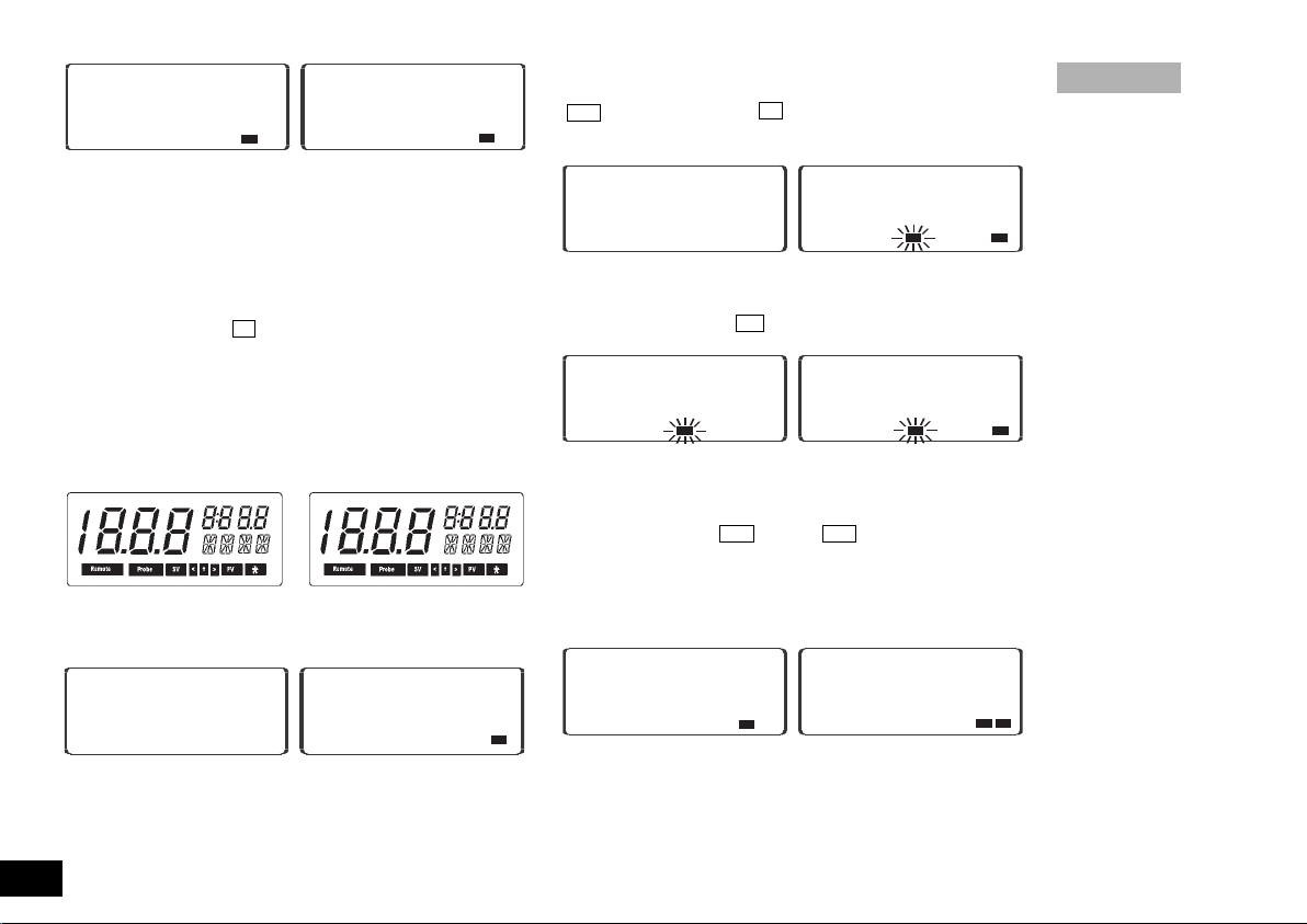
Betriebsart B:
I30
I30
I
min
/
PV
PV
minn
i
356
.
358
:
I30
KS B
✱
230
SAFE
minn
i
358
:
S
V
OK
✱
I30
I30
I
min
/
PV
PV
minn
i
356
.
358
:
✱
I30
I
min
/
S
V
minn
i
358
:
SV
✱
Beim Einschalten des Gerätes werden die vor dem Ausschalten
(Netz AUS) eingestellten Sollwerte für die Drehzahl und Zeiteinstellung übernommen. Die eingestellte Drehzahlobergrenze
wird bei der Wahl dieser Betriebsart aus der Betriebsart
nommen und kann nicht verändert werden.
Beim Einschalten mit dem Netzschalter wird ein B für die
Betriebsart B und ein * auf dem rechten Display angezeigt.
Nach einer Netzunterbrechung läuft das Gerät in der Betriebsart
B nicht von selbst wieder an.
Nach der Wahl der Betriebsart und dem Einschalten des Gerätes
wird der folgende Ablauf auf dem Display angezeigt.
a.) Alle Anzeigeelemente der Digitalanzeigen sind ca. 2 sec aktiviert.
b.) Anzeige der Gerätetype (linkes Display) und Betriebsart
(rechtes Display) ca. 2 sec.
A über-
Im rechten Display wird der abgespeicherte oder neu eingestellte Zeitsollwert (z.B.
SV angezeigt. Am Stern * im Display für die Zeiteinstellung
erkennt der Anwender daß die Betriebsart B aktiv ist.
d.) Daraufhin wird in der linken Anzeige der abgespeicherte oder
neu eingestellte Drehzahlsollwert (z.B. 130) mit der Einheit
1/min und blinkendem SV angezeigt.
e.) Durch Drücken des linken bzw. rechten Drehknopfes kann
der Schüttler in Betrieb genommen werden. Die Drehzahl- und
Zeitistwerte werden daraufhin groß auf dem Display angezeigt.
Außerdem wird statt
zeigt. Der Istwert der Zeiteinstellung muß ab diesem Zeitpunkt
als Restlaufzeit des Schüttelvorganges verstanden werden. Ist
die Restlaufzeit auf Null abgelaufen, hört der Schüttler auf zu
schütteln.
3:58) mit der Angabe h min und blinkendem
SV der Text PV auf dem Display ange-
c.) Im linken Display wird die eingestellte (bzw. abgespeicherte)
Drehzahlobergrenze aus der Betriebsart A mit SAFE und OK ca.
2 sec lang angezeigt. Die angezeigte Drehzahlobergrenze kann
nicht verändert werden.
8
Artisan Technology Group - Quality Instrumentation ... Guaranteed | (888) 88-SOURCE | www.artisantg.com
Betriebsart C:
Die eingestellte Drehzahlobergrenze wird bei Wahl dieser Betriebsart aus der Betriebsart
ändert werden. Die aus der Betriebsart
A übernommen und kann nicht ver-
A oder B eingestellten
032007
Page 10
Sollwerte für die Drehzahl und Zeit werden übernommen und
I30
KS C
✱
230
SAFE
minn
i
358
:
SV
OK
✱
I30
I
min
/
S
V
minn
i
358
:
SV
✱
I30
I30
I
min
/
P
V
PV
minn
i
356
.
358
:
✱
können nicht verändert werden. Beim Einschalten mit dem
Netzschalter wird ein C für die Betriebsart C und blinkender *
auf dem Display angezeigt.
Nach einer Netzunterbrechung läuft das Gerät in
Betriebsart
Nach der Wahl der Betriebsart und dem Einschalten des Gerätes
wird der folgende Ablauf auf dem Display angezeigt.
a.) Alle Anzeigeelemente der Digitalanzeigen sind ca. 2 sec aktiviert.
b.) Anzeige der Gerätetype (linkes Display) und Betriebsart (rechtes Display) ca. 2 sec.
c.) Im rechten Display wird der abgespeicherte Zeitsollwert (z.B.
3:58) mit der Angabe h min und SV angezeigt. Im linken
Display wird die eingestellte (bzw. abgespeicherte) Drehzahlobergrenze aus der Betriebsart A mit SAFE und OK ca. 2 sec
lang angezeigt. Die angezeigte Drehzahlobergrenze kann nicht
durch Drücken und Drehen des Drehknopfes verändert werden.
C von selbst wieder an.
Drehzahlsollwert (z.B.
Einheit 1/min und SV angezeigt.
e.) Durch Drücken des linken bzw. rechten Drehknopfes kann
der Schüttler in Betrieb genommen werden. Die Drehzahl- und
Zeitistwerte werden daraufhin groß auf dem Display angezeigt.
Außerdem wird statt SV der Text PV auf dem Display angezeigt. Der Istwert der Zeiteinstellung muß ab diesem Zeitpunkt
als Restlaufzeit des Schüttelvorganges verstanden werden. Ist
die Restlaufzeit auf Null abgelaufen, hört der Schüttler auf zu
schütteln.
Umschalten der Betriebsarten:
Zum Umschalten der Betriebsarten sind folgende Schritte notwendig:
a.) Ausschalten des Gerätes mit dem Netzschalter
b.) Beide Drehknöpfe gedrückt halten und das Gerät mit dem
Netzschalter einschalten, nach ca. 1 sec können die Drehknöpfe losgelassen werden
Zwischen den Betriebsarten A, B und C kann nicht beliebig
c.)
umgeschaltet werden, sondern es kann nur durch wiederholen der oberen beiden Schritte umgeschaltet werden.
A - Schritt a.) + b.) >B - Schritt a.) + b.) >C - Schritt a.) +
A - Schritt a.) + b.) >
b.) >
130) aus Betriebsart A oder B mit der
032007
d.) Daraufhin wird in der linken Anzeige der abgespeicherte
Artisan Technology Group - Quality Instrumentation ... Guaranteed | (888) 88-SOURCE | www.artisantg.com
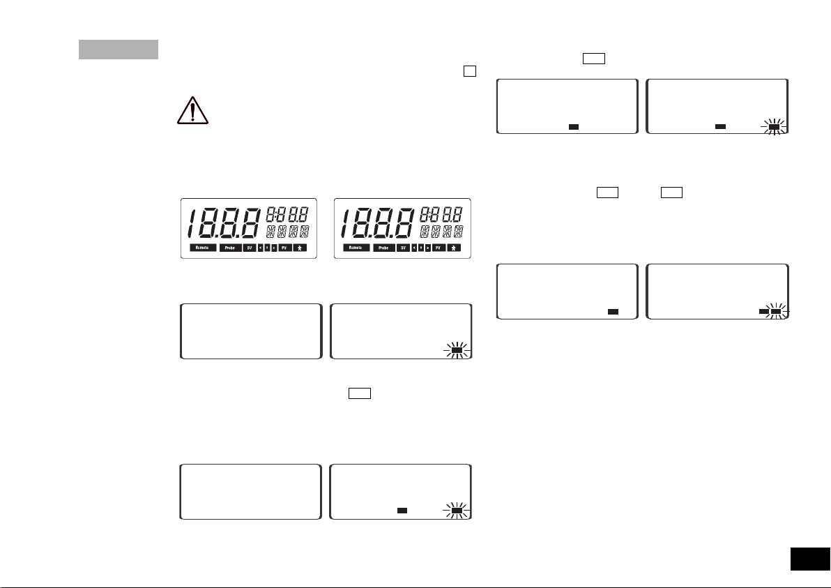
Einstellung des akustischen Zeitablaufsignals
Zum Aktivieren bzw. Deaktivieren des akustischen Zeitablaufsignals sind folgende Schritte notwendig:
9
Page 11
a.) Ausschalten des Gerätes mit dem
SV
SV
SV
Netzschalter.
b.) Rechter Drehknopf gedrückt halten
und das Gerät mit dem Netzschalter einschalten, nach ca. 5 sec
Drehknopf loslassen.
c.) Durch drücken des rechten Dreh-
knopfes kann das akustische Zeitablaufsignal aktiviert
(SOUND ON)
bzw. deaktiviert (SOUND OFF)
werden.
Hinweis: Ist das Zeitablaufsignal aktiviert, wird der Ablauf der
eingestellten Zeit durch eine Signalfolge (3 mal 5 kurze Töne in
ca. 10 sec Abständen) angezeigt.
Einstellung der Arretierung (Lock - Funktion)
Die Arretierung (Lock - Funktion) des Schütteltisches kann in
direktem Anschluss an die Einstellung des akustischen
Zeitablaufsignals aktiviert bzw. deaktiviert werden.
Zum Aktivieren bzw. Deaktivieren sind folgende Schritte notwendig:
a.) Ausschalten des Gerätes mit dem
Netzschalter.
b.) Rechter Drehknopf gedrückt halten
und das Gerät mit dem Netzschalter einschalten, nach ca. 5 Sekunden Drehknopf loslassen. Nach
Durchlaufen der Sound
On/Off
Routine ist das Aktivieren bzw.
Deaktivieren der Arretierung möglich.
c.) Durch Drücken des rechten Drehknopfes kann die
Arretierung (Lock - Funktion) aktiviert (
On) bzw. deaktiviert (Lock
Off) werden.
Im rechten Display wird die aktivierte Arretierfunktion (Lock Funktion) durch das Symbol = angezeigt. Ist das Symbol =
10
Artisan Technology Group - Quality Instrumentation ... Guaranteed | (888) 88-SOURCE | www.artisantg.com
nicht im rechten Display zu sehen, ist die Arretierfunktion des
Schütteltisches ausgeschaltet.
ACHTUNG! Nach einem Stromausfall führt der entriegelte (frei bewegliche) Schütteltisch solange eine
Kreisbewegung aus, bis die Arretierung den
Schütteltisch fixieren kann.
Einstellen der Schüttelzeit
Basic - Variante
Die für den Schüttelvorgang notwendige Zeit wird mit Hilfe des
rechten Drehknopfes eingestellt. Bei der Schüttelzeiteinstellung
wird zwischen Dauerbetrieb und Zeitbetrieb unterschieden.
Wird der Dauerbetrieb gewählt (On-LED leuchtet) kann der
Schüttler bei vorher vorgegebener Drehzahl beliebig lange seine
Schüttelfunktion ausführen.
Bei der Wahl des Zeitbetriebes kann der Schüttelvorgang max.
50 min dauern. Die eingestellte Zeit wird durch die LED-Zeile
angezeigt. Die blinkende LED zeigt die aktuelle Restlaufzeit an.
Nach dem Erlöschen aller LED’s im Zeitbetrieb schaltet das
Gerät in den Off-Betriebszustand und der Schüttelvorgang ist
beendet.
Hinweis: Die aktuell eingestellte Zeit kann zu jeder Zeit verändert werden. Wird die Zeiteinstellung nach rechts über die
50 min geregelt, erlischt der LED-Balken und die LED des OnBetriebszustandes (Dauerbetrieb) beginnt zu leuchten. Wird der
Drehknopf weiterhin auf Rechtsanschlag gehalten, springt das
Gerät zuerst in den Off-Betriebszustand (Stillstand) und dann
wieder in den Zeitbetrieb. Das Gleiche gilt in umgekehrter
Reihenfolge, wenn der rechte Drehknopf über einen längeren
Zeitraum auf Linksanschlag gedreht wird.
032007
Page 12
Nach einem Stromausfall wird die eingestellte Zeit (Zeitbetrieb
345
345
I
min
/
PV
PV
minn
i
959
.
959
:
345
345
I
min
/
PV
PV
minn
i
959
:
345
I
min
/
PV
PV
minn
i
959
:
345
345
I
min
/
PV
PV
minn
i
959
.
959
:
345
345
I
min
/
PV
PV
minn
i
959
:
345
I
min
/
PV
PV
minn
i
959
:
oder Dauerbetrieb) gelöscht und das Gerät schaltet in den OffBetriebszustand (Stillstand).
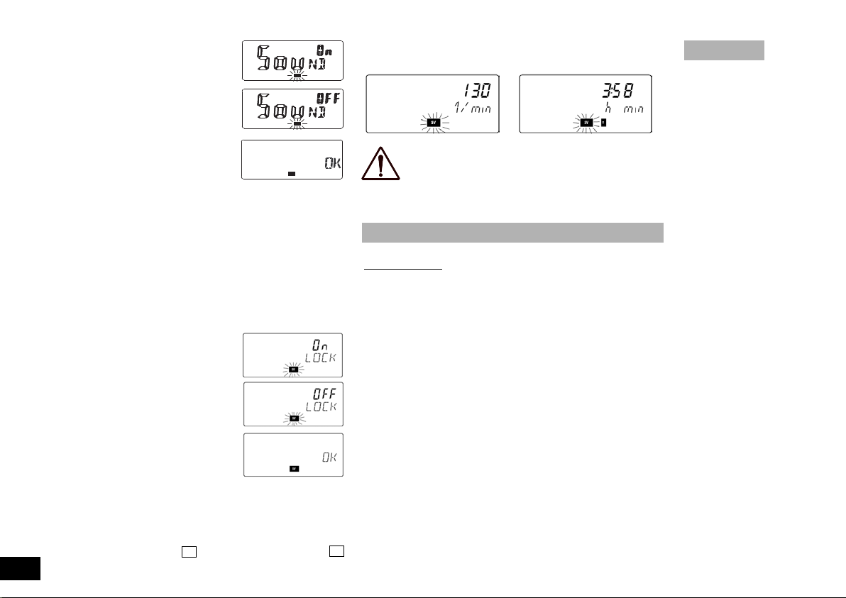
Control - Variante
Die für den
Schüttelvorgang notwendige Zeit wird
mit Hilfe des
rechten Drehknopfes eingestellt und über
das rechte Display angezeigt.
Ist eine Sollzeit
(max. 9h 59min)
im rechten Display eingestellt
oder von vorhergehenden Schüttelvorgängen abgespeichert, kann bei Vorgabe einer Solldrehzahl mit dem linken Drehknopf der Schüttelvorgang aktiviert bzw. beendet werden.
Durch Drücken des rechten Drehknopfs wird der Zeitbetrieb verlassen und der Schüttelvorgang unterbrochen.
Zeitbetrieb in Betriebsart A
Dauerbetrieb in Betriebsart A
Anzeige nach Stromausfall in Betriebsart A
ACHTUNG! Nach einem Stromausfall läuft das Gerät
in Betriebsart A und B nicht von selbst wieder an. In
Betriebsart C läuft das Gerät nach einem Stromausfall
von selbst wieder an.
betrieb oder Zeitbetrieb aktiv ist. Das bedeutet für den Anwender, daß er im Off- Betriebszustand eine Drehzahl einstellen
kann, die er für den Dauerbetrieb oder mehrere Schüttelvorgänge im Zeitbetrieb benötigt.
HINWEIS: Nach einem Stromausfall wird die eingestellte Zeit
gelöscht und das Gerät schaltet in den Off-Betriebszustand (Stillstand). Die eingestellte Drehzahl bleibt eingestellt.
Control - Variante
Die für den
Schüttelvorgang notwendige Solldrehzahl
und Drehzahlobergrenze
(max. 800 1/min
wird mit Hilfe
des linken Drehknopfes eingestellt und über
das linke Display angezeigt.
Der Dauerbetrieb wird durch
drücken des linken Drehknopfes aktiviert. Ist im Dauerbetrieb
eine Sollzeit im rechten Display eingestellt oder von vorhergehenden Schüttelvorgängen abgespeichert, kann durch drücken
des rechten Drehknopfes der Schüttelvorgang im Zeitbetrieb
fortgesetzt werden. Der Schüttelvorgang kann durch drücken
des linken bzw. rechten Drehknopfes beendet werden.
Zeitbetrieb in Betriebsart A
Dauerbetrieb in Betriebsart A
Anzeige nach Stromausfall in Betriebsart A
032007
Einstellen der Drehzahl
Basic - Variante
Die Drehzahl (max. 800 1/min) kann durch drehen des linken
Drehknopfes eingestellt werden. Hierbei ist darauf zu achten,
daß der Schüttler erst dann zu laufen beginnt, wenn der Dauer-
Artisan Technology Group - Quality Instrumentation ... Guaranteed | (888) 88-SOURCE | www.artisantg.com
ACHTUNG! Nach einem Stromausfall läuft das Gerät
in Betriebsart A und B nicht von selbst wieder an. In
Betriebsart C läuft das Gerät nach einem Stromausfall
von selbst wieder an.
11
Page 13

Aufsätze
Die von IKA empfohlenen Aufsätze müssen auf dem Schütteltisch gut befestigt werden um ein sicheres Arbeiten zu gewährleisten. Außerdem dürfen die in den Diagrammen dargestellten
nutzbaren Gewichts- und Drehzahlbereiche (schraffierte Fläche)
nicht überschritten werden.
AS 130.1 Universalaufsatz
Anpassung an jegliche Gefäßform durch universelle, stufenlos
einstellbare Spannwalzen möglich.
Der Universalaufsatz besteht aus:
AS 1.30 Basishalterung 1x Abmessung BxHxT
AS 1.5 Befestigungsschraube 4x in mm
AS 1.31 Spannwalze 3x 260 x 90 x 235
ACHTUNG! Die Basishalterung des Universalaufsatzes wird
über vier seitliche Klemmschrauben an dem Schütteltisch befestigt.
AS 130.2 Halteklammeraufnahme
Die Halteklammeraufnahme eignet sich durch die Ergänzungsvielfalt der Halteklammern (AS2.1, AS2.2, AS2.3, AS2.4 und
AS2.5) zum Bearbeiten von z.B. Rundkolben, Messkolben und
Erlenmeyerkolben.
Bestückung empfohlen / maximal
AS 2.1 Halteklammer 12 / 12 Abmessung BxHxT
AS 2.2 Halteklammer 8 / 9 in mm
AS 2.3 Halteklammer 5 / 8 230 x 24 x 235
AS 2.4 Halteklammer 4 / 4
AS 2.5 Halteklammer 2 / 4
ACHTUNG! Die Halteklammeraufnahme wird über vier seitliche Klemmschrauben an dem Schütteltisch befestigt.
AS 130.3 Schalenaufsatz
Für sanftes Schütteln im niedrigen Drehzahlbereich, z.B. für
Petrischalen oder Kulturflaschen. Der Schalenaufsatz ist mit
einer Antirutschfolie versehen, die ein Wandern der Schalen
während des Schüttelvorganges verhindern.
12
Artisan Technology Group - Quality Instrumentation ... Guaranteed | (888) 88-SOURCE | www.artisantg.com
Abmessung BxHxT
in mm
420 x 33 x 270
ACHTUNG! Der Schalenaufsatz wird über vier seitliche Klemmschrauben an dem Schütteltisch befestigt.
AS 130.4 Reagenzglasaufnahme
Zum intensiven Schütteln von z.B. Röhrchen, Reagenzgläsern,
Küvetten und Zentrifugenröhrchen. Spannbereich von ø10mm
bis ø16mm für maximal 64 Röhrchen.
Abmessung BxHxT
in mm
228 x 95 x 234
ACHTUNG! Die Reagenzglasaufnahme wird über vier seitliche
Klemmschrauben an dem Schütteltisch befestigt.
Nach längerem Schütteln von Gefäßen mit großem Durchmesser, müssen beim Umrüsten auf Gefäße mit kleinerem Durchmesser die Klemmlaschen vorsichtig zurückgebogen werden,
um eine sichere Klemmung zu erhalten.
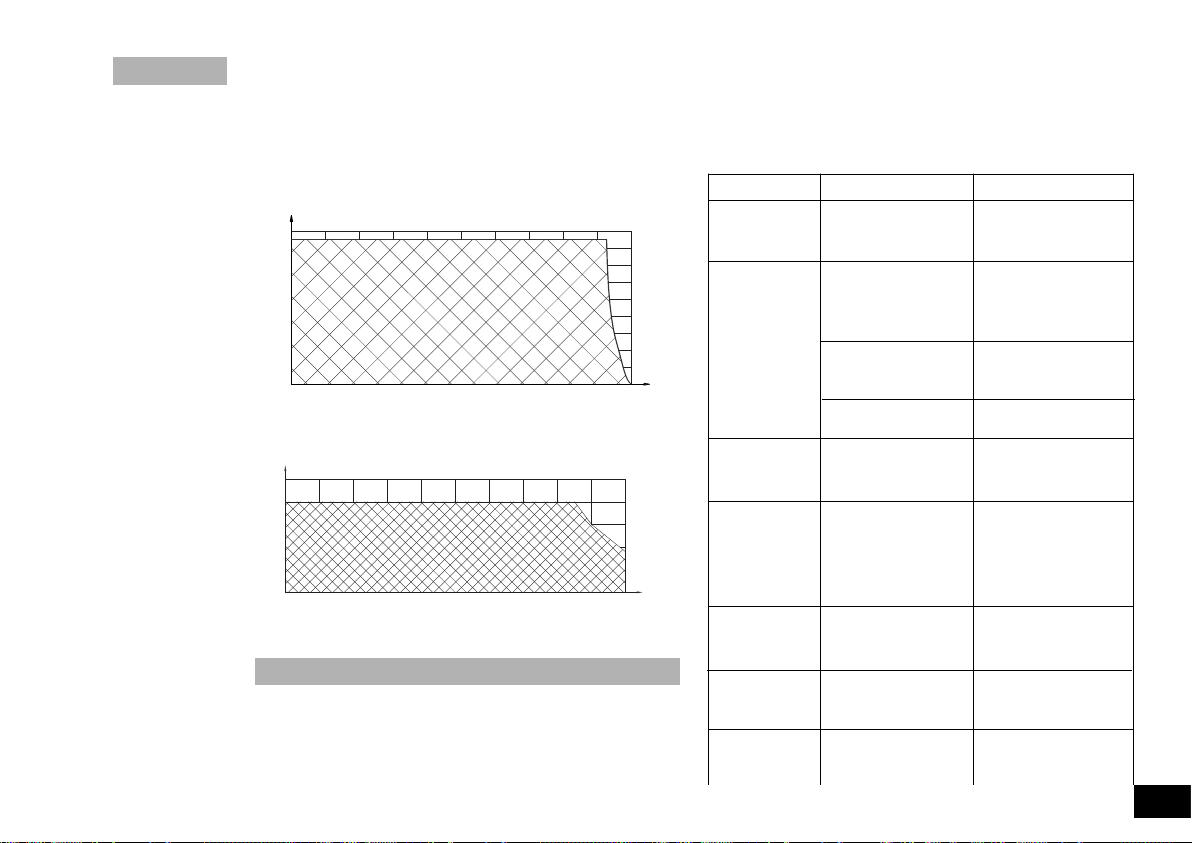
Auflagegewicht (Zuladung)
Der Schüttler darf nur im Bereich des nutzbaren Gewichts- und
Drehzahlbereich (siehe Diagramm - schraffierte Fläche) betrieben werden um ein sicheres Arbeiten zu gewährleisten. Achten
Sie darauf, daß die Aufstellfläche auf die der Schüttler gestellt
wird, sauber und eben ist. Ansonst kann der im Diagramm dargestellte Arbeitsbereich (schraffierte Fläche) im Schüttelbetrieb
nicht genutzt werden.
Wird der Schüttler mit seiner Umgebung verschraubt (d.h. in
eine Anlage eingebaut), ist im Betrieb darauf zu achten, dass
infolge ungünstiger Beladung und Schwerpunktlage, dynamische Kräfte auftreten. Diese können zum einen die Umgebung in
Schwingung versetzen oder den Tisch zu unkontrollierbaren
Schwingungen anregen. Wird ein unruhiger Lauf des Gerätes
032007
Page 14
1/min
0 80 560
160
240 320 400 480 640 800720
g
2000
1750
1500
1000
500
0
1250
750
250
1/min
0 80 560
160
240 320 400 480 640 800720
g
2500
2000
1500
1000
500
0
032007
bemerkt, muss auf jeden Fall die Drehzahl soweit reduziert wer-
den, bis keine Laufunruhen mehr auftreten.
Achten Sie darauf, dass einzelne Schüttelgefäße mittig und mehrere Schüttelgefäße gleichmäßig auf dem Schütteltisch plaziert
und gut befestigt sind.
und anschließendes einschalten des Gerätes den Betrieb fortzusetzen. Sollte sich ein Fehler auch nach längerer Pause nicht
beheben lassen, wenden Sie sich bitte an unseren Service.
Teilen Sie uns den angezeigten Fehlercode in jedem Falle mit.
Dies vereinfacht die Fehlersuche und ermöglicht eine erste
Stellungnahme.
AS 130.1 Universalaufsatz
Fehlermeldung
Fehler Fehlerursache
Off - LED (rot) Das Potentiometer für -Zu schnelle Veränderung
1x blinken / die Drehzahleinstellung des Drehzahlsollwertes
2 sec Pause gibt keinen Sollwert vor -Interner Gerätefehler
Off - LED (rot) Zulässige Motortempe- -Zulässiges Auflagege-
2x blinken / ratur überschritten wicht überschritten
2 sec Pause -Zulässige Umgebungs-
Motor blockiert -Schütteltisch wird durch
Lesegabelsignal nicht -Interner Gerätefehler
AS 130.4 Reagenzglasaufnahme
Off - LED (rot) Maximal einstellbare -Resonanzverhalten
3x blinken / Drehzahl des Gerätes des Versuchsaufbau
2 sec Pause überschritten
vorhanden
Off - LED (rot) Motorstillstand für Ge- -Beim Einschalten des
4x blinken / räteeinschaltroutine Gerätes muß gewährlei-
2 sec Pause (Sicherheitsabfrage) stet sein, daß der Motor
nicht gewährleistet keine Drehbewegung
Off - LED (rot) Sicherheitsrelais kann -Interner Gerätefehler
5x blinken / nicht angesteuert
Fehlermeldungen (Error codes)
Fehlermeldung Basic:
ACHTUNG! Tritt eine Fehlermeldung auf, wird ein akustisches
Warnsignal erzeugt und die rote Off-Signalleuchte im Anzeige-
feld leuchtet auf. Versuchen Sie bitte zuerst durch abschalten
Artisan Technology Group - Quality Instrumentation ... Guaranteed | (888) 88-SOURCE | www.artisantg.com
2 sec Pause werden
Off - LED (rot) Der Schalter für die -Interner Gerätefehler
6x blinken / TIME-Funktion gibt
2 sec Pause keinen Sollwert vor
Off - LED (rot) Spannungsversorgung -Das Gerät wird mit
7x blinken / nicht in Ordnung Unter- oder Überspann-
2 sec Pause ung betrieben. (Zulässi-
temperatur überschritten
äußere Einwirkung in der
Hubbewegung behindert
mehr ausführt
13
Page 15
ger Spannungsbereich
5
10
15
1
6
11
Analog GND
1V = 1000 1/min
5
10
15
1
6
11
Analog GND
RS232_GND
TxD
RxD
RTS
CTS
1V = 1000 1/min
siehe Techn. Daten)
Off - LED (rot) Triac nicht ansteuerbar -Interner Gerätefehler
8x blinken /
2 sec Pause
Fehlermeldung Control:
ACHTUNG! Tritt eine Fehlermeldung auf, wird ein akustisches
Warnsignal erzeugt und auf dem Display angezeigt. Versuchen
Sie bitte zuerst durch abschalten und anschließendes einschalten des Gerätes den Betrieb fortzusetzen. Sollte sich ein Fehler
auch nach längerer Pause nicht beheben lassen, wenden Sie
sich bitte an unseren Service. Teilen Sie uns den angezeigten
Fehlercode in jedem Falle mit. Dies vereinfacht die Fehlersuche
und ermöglicht eine erste Stellungnahme.
Fehlermeldung
Fehler Fehlerursache
Er 2 im Remotebetrieb bei -Schnittstelle nicht ge-
aktiver Watchdogfunk- steckt
tion in Modus 1 keine -PC sendet innerhalb der
Kommunination zwischen
gesetzten Watchdogzeit
PC und Schüttelgerät keine Daten
Er 3 Geräteinnentempera- -Zulässige Umgebungs-
tur zu hoch temperatur überschritten
Er 4 Blockieren des Motors -Schütteltisch wird in der
oder überlastet Hubbewegung behindert
Er 9
Lesegabelsignal nicht ok
Fehler beim Auslesen der
--Interner Gerätefehler
--BLP Logik
gespeicherten Werte
Er 41 Triac defekt --Interner Gerätefehler
Er 42 Sicherheitsrelais defekt --Interner Gerätefehler
WD Im Remotebetrieb bei -Schnittstelle nicht ge-
14
aktiver Watchdogfunk- steckt
tion in Modus 2 keine -PC sendet innerhalb der
Kommunination zwischen
gesetzten Watchdogzeit
PC und Schüttelgerät keine Daten
Artisan Technology Group - Quality Instrumentation ... Guaranteed | (888) 88-SOURCE | www.artisantg.com
Schnittstelle und Ausgänge
(Nur Version KS 130 control)
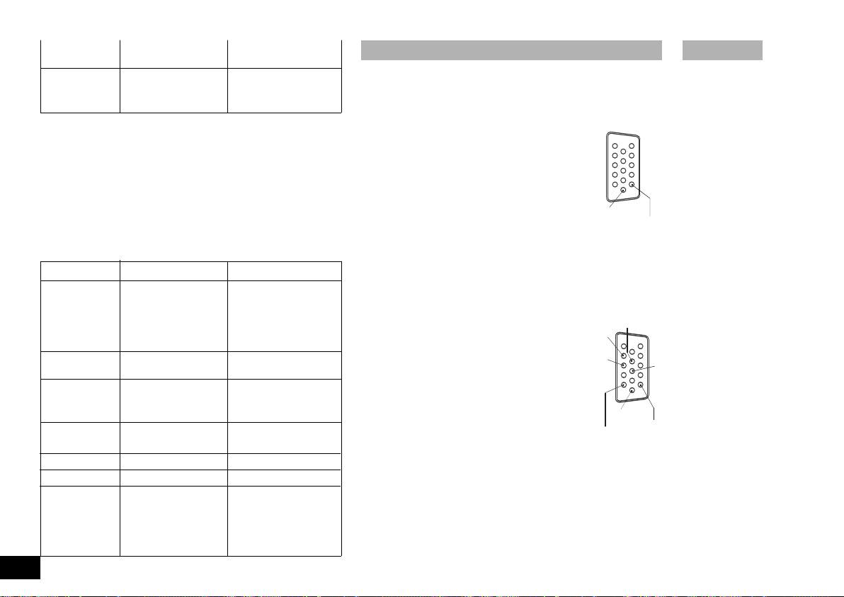
Das Gerät KS 130 control ist auf der Geräterückseite mit einem 15-poligen
SUB-D-Buchsenstecker ausgerüstet. Die Pins sind in Betrieb mit analogen
und seriellen Signalen belegt.
Analogausgang
An den analogen Pins liegen Spannungswerte für die
Meßgröße Drehzahl an.
(10) Analog GND
(15) Meßwert Drehzahl 1VDC / 1000 1/min
Serielle Schnittstelle RS 232 C
Die serielle Belegung der Buchse kann dazu verwendet werden, das Gerät
extern mittels PC und geeigneter Anwendungsprogramme zu steuern.
Konfiguration der seriellen Schnittstelle RS 232 C
• Die Funktion der Schnittstellenleitung zwischen Laborgerät und Automatisierungssystem sind eine Auswahl aus den in der
EIA-Norm RS234C, entsprechend DIN 66020 Teil 1 spezifizierten Signale. Die Belegung der Signale ist dem Bild
zu entnehmen.
• Für die elektronischen Eigenschaften der Schnittstellen und die Zuordnung der Signalzustände gilt die
Norm RS 232 C, entsprechend DIN 66259 Teil 1.
• Übertragungsverfahren:Asynchrone Zeichenübertragung in Start-Stop Betrieb.
• Übertragungsart: Voll Duplex
• Zeichenformat: Zeichenerstellung gemäß Datenformat in DIN
66022 für Start-Stop Betrieb. 1Startbit; 7Zeichenbits; 1Paritätsbit (grade= Even); 1Stopbit.
• Übertragungsge-
schwindigkeit: 9600 Bit/s
• Datenflußsteuerung: Hardwarehandshake RTS/CTS
• RTS: (PIN 7) LOW (positive Spannung)
/ PC darf senden
032007
Page 16
032007
• RTS: (PIN 7) HIGH (negative Spannung)
/ PC darf nicht senden
• CTS: (PIN 8) LOW (positive Spannung)
/ PC empfangsbereit
• CTS: (PIN 8) HIGH (negative Spannung)
/ PC nicht empfangsbereit
• Zugriffsverfahren: Eine Datenübertragung vom Schüttler zum
Rechner erfolgt nur auf Anforderung des
Rechners.
Befehlssyntax
Für den Befehlssatz gilt folgendes:
• Die Befehle werden generell vom Rechner (Master) an das Laborgerät
(Slave) geschickt.
• Das Laborgerät sendet ausschließlich auf Anfrage. Auch Fehlermeldun-
gen können nicht spontan vom Laborgerät an den Rechner (Automatisierungssystem) gesendet werden.
• Die Befehle und Parameter, sowie aufeinanderfolgende Parameter wer-
den durch wenigstens eine Leerzeile getrennt. (Code: hex 0x20)
• Jeder einzelne Befehl inklusive Parameter und Daten und jede Antwort
werden mit CR LF abgeschlossen (Code: hex 0x0D und 0x0A) und haben
eine maximale Länge von 80 Zeichen.
• Das Dezimaltrennzeichen in einer Fließkommazahl ist der Punkt (Code:
hex 0x2E).
Die vorhergehenden Ausführungen entsprechen weitgehend den
Empfehlungen des NAMUR-Arbeitskreises (NAMUR-Empfehlungen zur
Ausführung von elektrischen Steckverbindungen für die analoge und digitale Signalübertragung an Labor-MSR Einzelgeräten (Rev. 1.1).
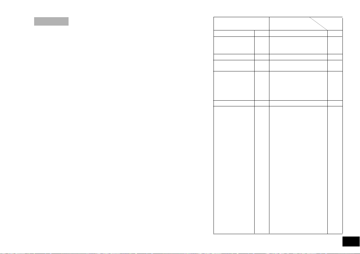
Übersicht der NAMUR-Befehle
(Nur Version KS 130 control)
Verwendete Abkürzungen:
X,y = Numerierungsparameter (Integerzahl)
M = Variablewert, Integerzahl
n = Variablewert, Fließkommazahl
X = 4 Drehzahl
X = 6 Drehzahlobergrenze („SAFE“ Drehzahl)
Artisan Technology Group - Quality Instrumentation ... Guaranteed | (888) 88-SOURCE | www.artisantg.com
NAMUR Befehle Funktion Anzeige
IN_PV_X X=4 Lesen des Ist-Wertes
OUT_SP_Xn X=4 Setzen des Ist-Wertes auf n
IN_SP_X X=4; 6 Lesen des gesetzten Ist-Wertes
START_X X=4 Einschalten der Geräte-
STOP_X X=4 Ausschalten der Gerätefunk-
RESET Ausschalten der Gerätefunktion
STATUS Ausgabe des Status
maximal bis zur eingestellten
Drehzahlobergrenze
(Remote) Funktion
tion. Die mit OUT_SP_X gesetzte Variable bleibt erhalten.
Beinhaltet den Befehl RMP_
STOP
1*: Betriebsart A
2*: Betriebsart B
3*: Betriebsart C
Manueller Betrieb ohne Störung
*0:
*1: Automatischer Betrieb Start
*2: Automatischer Betrieb Stop
<0: Fehlercode: (-1)
-2: Er2 / WD
-3: Er3
-4: Er4
-9: Er9
-41: Er41
-42: Er42
-83: Falsche Parität
-84: Unbekannter Fehler
-85: Falsche Befehls-
-86: Ungültiger Sollwert
-87: Nicht genügend Speicher
zusätzlich
Remote
Remote
(ohne Störung)
(ohne Störung)
reihenfolge
15
Page 17
RMP_IN_X X=4 Lesen der aktuellen Segment-
RMP_IN_X_y X=4 Lesen des Endwertes und der Ram-
RMP_OUT_y n hh:mm:ss
RMP_START_X X=4
RMP_STOP_X X=4
RMP_PAUSE_X X=4 Anhalten der Rampenfunktion.
RMP_CONT_X X=4 Fortsetzung der Rampenfunktio-
RMP_RESET_X Fortsetzung der Rampenfunktio-
RMP_LOOP_SET_X X=4 Arbeiten der Rampe in einer
RMP_LOOP_RESET_X X=4 Beenden der Rampen Schleife
IN_TYPE Anforderung der Laborgeräteer-
IN_NAME Anforderung der Bezeichnung
OUT_NAME
name
16
nummer der Rampe. Bei nicht
gestarteter Rampe: 0
pensegmentzeitdauer (hh:mm:ss)
des Rampensegments y.
X=4 Setzen des Endwertes (n) und
der Rampensegmentzeitdauer
(hh:mm:ss) für das Rampensegment y
Einschalten der Rampenfunktion
beginnend mit dem Rampenment Nr. 1 (Nur möglich nach
vorherigem START_X. Nach
RMP_STOP_X ist START_X
nicht notwendig.
Ausschalten der Rampenfunktion
Sollwert=0 (Rampe bleibt erhalten, d.h. Rampe kann mit
RMP_START_X wieder gestartet
werden.
Einfrieren von aktuellem Sollwert
und aktueller Rampensegmentzeit
nen (nach vorherigem
RMP_PAUSE_X).
nen und Löschen aller vorgegebenen Rampensegmente
Schleife
kennung
Ausgabe der Bezeichnung name
(Max. 6 Zeichen, Default: IKA_S_)
Artisan Technology Group - Quality Instrumentation ... Guaranteed | (888) 88-SOURCE | www.artisantg.com
OUT_WD1@m Watchdog Modus 1: Tritt das
WD1-Ereignis ein, so wird der
Schüttelvorgang ausgeschaltet
und es wird Er 2 angezeigt
Setzen der Watchdogzeit auf m
(10...1800) sec, mit Echo der
Watchdogzeit. Dieser Befehl startet die Watchdogfunktion und
muß immer innerhalb der gesetzten Watchdogzeit gesendet
werden.
OUT_WD2@m Watchdogmodus 2: Tritt das
WD2-Ereignis ein, so wird der
Drehzahlsollwert auf die gesetzte WD-Sicherheitssolldrehzahl
gesetzt. Die Warnung WD wird
angezeigt
Das WD2-Ergebnis kann mit
OUT_WD2@0 zurückgesetzt
werden.
Setzen der Watchdogzeit auf m
(10...18000) sec, mit Echo der
Watchdogzeit. Dieser Befehl
startet die Watchdogfunktion und
muß immer innerhalb der gesetzten Watchdogzeit gesendet
werden.
OUT_SP_42@n Setzen der WD-Solldrehzahl mit WD
Echo des gesetzten Wertes.
Verbindungsmöglichkeit zwischen
Laborgerät und PC
(Nur Version KS 130 control)
Zur Verbindung zwischen Laborgerät (nur Control-Variante) und PC sind von
IKA folgende Adapter und Adapterkabel erhältlich.
032007
Page 18

PC 5.1 Adapter IKA - Control
Der Adapter PC 5.1 splittet die analogen und seriellen Signale
auf. Die analogen Ausgänge werden auf eine 7-polige Buchse
gemäß der Namur - Empfehlungen gelegt, die seriellen Signale
auf einen 9-poligen Sub-D-Buchsenstecker (RS 232 C).
PC 1.5 Kabel
Das Kabel PC 1.5 wird zur Verbindung der 15-poligen Buchse
zum PC (25-poliger Stecker) benötigt.
PC 2.1 Kabel
Das Kabel PC 2.1 wird zur Verbindung der 9-poligen Buchse zum
PC benötigt.
PC 1.2 Adapter
Der PC 1.2 Adapter wird zur Verbindung der 9-poligen Buchse
mit einer 8fach-seriellen Schnittstelle (25-poliger Stecker)
benötigt.
AK 2.1 Kabel
Das Kabel AK 2.1 wird zur Verbindung der 7-poligen Buchse mit
einem Schreiber (4mm Bananenstecker) benötigt.
AK 2.2 Kabel
Das Kabel AK 2.2 wird zur Verbindung der 15-poligen Buchse mit
einem Schreiber (4mm Bananenstecker) benötigt.
Motorschutz/Sicherheitseinrichtungen
Ein Blockieren bzw. Belasten des Motors über die zulässige
Motortemperatur hinaus, führt zum automatischen Abschalten
des Gerätes durch den Sicherheitskreis. Zur Fehlerbehebung
muss das Auflagegewicht reduziert werden - lassen Sie das
Gerät abkühlen. Das Gerät muss aus- und wieder eingeschaltet
werden.
Durch einen Sicherheitskreis wird der Motor im Störfall sofort
bleibend ausgeschaltet. Ein Störfall tritt dann auf, wenn die
sichere Funktion des Geräters nicht gewährleistet ist. Ein Störfall
wird bei der Basic-Variante durch das Aufleuchten und Blinken
der roten Off-Signalleuchte und bei der Control-Variante durch
eine Error-Meldung auf dem Display der Drehzahlanzeige angezeigt (Siehe Abschnitt „Fehlermeldungen“).
Wartung und Reinigung
Der Schüttler KS 130 basic und KS 130 control arbeitet wartungsfrei. Er unterliegt lediglich der natürlichen Alterung der
Bauteile und deren statistischer Ausfallrate.
Bei Ersatzteilbestellungen geben Sie bitte die auf dem
Typenschild angegebene Fabrikationsnummer, den
Gerätetyp sowie die Positiosnummer und die Bezeichnung
des Ersatzteiles an.
Bitte senden Sie nur Geräte zur Reparatur ein, die gereinigt und
frei von gesundheitsgefährdenden Stoffen sind. Reinigen Sie
IKA-Geräte nur mit von IKA freigegebenen Reinigungsmittel.
Verwenden Sie zum Reinigen von:
Farbstoffen Isopropanol
Baustoffen Tensidhaltiges Wasser/Isopropanol
Kosmetika Tensidhaltiges Wasser/Isopropanol
Nahrungsmittel Tensidhaltiges Wasser
Brennstoffen Tensidhaltiges Wasser
Bei nicht genannten Stoffen fragen Sie bitte bei IKA nach. Tragen
Sie zum Reinigen der Geräte Schutzhandschuhe. Elektrische
Geräte dürfen zu Reinigungszwecken nicht in das Reinigungsmittel gelegt werden. Bevor eine andere als die vom Hersteller
empfohlene Reinigungs- oder Dekontaminierungsmethode
angewandt wird, hat sich der Benutzer beim Hersteller zu vergewissern, daß die vorgesehene Methode das Gerät nicht zerstört.
Achten Sie darauf, daß zur Befestigung des Motors auf der
Bodengruppe nur die von IKA vorgeschriebenen Schrauben verwendet werden um die doppelte Schutzisolierung des Gerätes
zu gewährleisten.
032007
Artisan Technology Group - Quality Instrumentation ... Guaranteed | (888) 88-SOURCE | www.artisantg.com
17
Page 19

Zubehör
AS 130.1 Universalaufsatz
AS 130.2 Halteklammeraufsatz
AS 130.3 Schalenaufsatz
AS 130.4 Reagenzglasaufnahme
(nur KS 130 control)
PC 5.1 Adapter IKA - Control
PC 1.5 Kabel
PC 2.1 Kabel AK 2.1 Kabel
PC 1.2 Adapter AK 2.2 Kabel
Technische Daten
Bemessungsspannung
oder VAC 115±10%
Frequenz Hz 50/60
Aufnahmeleistung W 45
Drehzahlbereich 1/min 0 - 800
Zul. Einschaltdauer
Zul. Umgebungstemperatur °C +5 bis +50
Zul. relative Feuchte % 80
Schutzart nach DIN EN 60529 IP 21
Schutzklasse I
Überspannungskategorie II
Verschmutzungsgrad 2
Geräteeinsatz über NN
Antrieb Drehzahlgeregelter
Schutz bei Überlast Temperaturfühler in
Sicherung im Gerätestecker
Radius des Orbit mm 2
18
VAC 230±10%
% 100
m max. 2000
Asynchronmotor
Motorwicklung
A T1AL (Id.Nr. 13 637 00)
Artisan Technology Group - Quality Instrumentation ... Guaranteed | (888) 88-SOURCE | www.artisantg.com
Schüttelbewegung kreisförmig Amplitude
Max. Beladung kg 2
Abmessungen (B x H x T) mm 270 x 98 x 316
Gewicht ( ... basic)
Gewicht ( ... control) kg 8,8
KS 130 basic
Drehzahleinstellung Analog (stufenlos)
Drehknopf Frontseite links
Drehzahlanzeige 10fach LED-Zeile mit Ska-
Max. Drehzahlabweichung
Zeiteinstellung
Drehknopf Frontseite rechts ter 10 Schritte von 5 - 50
Zeitanzeige 10fach LED-Zeile mit Ska-
Max. Zeitabweichung
KS 130 control
Drehzahleinstellung Digital
Drehknopf Frontseite links (1 Schritt = 10 1/min)
Drehzahlanzeige LCD - Display
Max. Drehzahlabweichung
Zeiteinstellung Digital
Drehknopf Frontseite rechts (1 Schritt = 1 min)
Zeitanzeige LCD - Display
Max. Zeitabweichung
Schnittstelle RS 232 C / Analog
Technische Änderung vorbehalten!
kg 7,7
la in 80 1/min Stufen
% ±10
drei Schaltstellungen / Tas-
min in 5 min Schritten
la in 5 min Stufen
% ±1
% ±1
max. 9h 59min
% ±1
032007
Page 20

032007
Contents
Page
Warranty 2
Safety instructions 19
Proper use 20
Unpacking 21
Useful facts 21
Commissioning 21
Switching on 22
Display 22
Operating modes 23
Setting the agitation time 26
Setting the speed 27
Attachments 28
Supported weight (load) 28
Error codes 29
Interface and outputs 30
Communication between laboratory instrument and PC
Motor protection / safety device 33
Maintenance and cleaning 33
Accessories 34
Technical data 34
List of spare parts / Spare parts diagram KS130 basic 52/53
List of spare parts / Spare parts diagram KS130 control 54/55
32
Safety instructions
In order to be able to use the appliance properly and safely, every
user must first read the operating instructions and observe the
safety instructions contained therein. Take care of these operating
instructions and keep them in a place where they can be accessed
by everyone.
Only staff who have been trained accordingly, know the appliance
and are authorised to carry out work in this field should use this
Artisan Technology Group - Quality Instrumentation ... Guaranteed | (888) 88-SOURCE | www.artisantg.com
appliance.
The machine may only be opened by trained specialists - even
during repairs. The machine is to be unplugged from the mains
before opening. Live parts inside the machine may still be live for
some time after unplugging from the mains.
NOTE ! Covering or parts that are capable of being
removed from the unit without accessory equipment have
to be reattached to the unit for safe operation in order to
prevent, for example, the ingress of fluids, foreign matter, etc. .
When working with the shaking unit, the user must select and
wear his personal protective equipment according to the mixing
hazard category. Defective or inadequate protective equipment
can expose the user to the risk
of spurting liquids, projectile
parts or being pulled in at the
shaking table or support.
Never touch moving parts (risk
of crushing, impact and cutting, see fig. 1: Danger zones).
Ensure that parts of the body,
hair or items of clothing cannot
be trapped by the motion
parts.
Please follow the relevant
safety instructions and guidelines, and occupational health
and safety regulations for use
in the laboratory.
Beware of the high dead
weight of the appliance when
transporting. Ensure that your
fingers do not get crushed when setting down the appliance.
Always install the appliance on a flat, stable non-slip base.
Before use, please ensure that the knob for setting the shaking
rate is at the left stop as the appliance starts up at the last shaking
rate which was set. Pay attention to the vessels on the shaking
table when setting the shaking rate. This will prevent any of the
fig. 1 danger zones
19
Page 21

medium to be shaken from spurting out of the sample vessels.
All accessories and vessels in place for the shaking process must
be firmly secured.
Shaking vessels which are not properly secured could get damaged or be projected out, thus causing injury. It is essential to regularly check that the vessels to be shaken and the attachments are
firmly secured, especially before using the appliance again.
If you notice that the device is not running smoothly, the speed
must always be reduced until no more uneveness occurs in the
operation.
Because of improper loading and the position of the center of
gravity, dynamic forces may arise during the agitation process
that cause the shaker to move about on the table. For limits on
the load or the weight placed on the agitation table at high shaking frequencies, please refer to the diagram in the section
„Weight placed on the table“ (just before the list of spare parts).
After an interruption in the power supply during an agitation procedure, the device will not start running again by itself.
Additional hazards to the user may occur if inflammable materials
are used during the shaking operation.
Furthermore, the shaking unit may only be used to stir those
materials or material mixtures that the user knows will not react
dangerously to the extra energy produced by the stirring. This also
applies to extra energy by means of solar radiation during the shaking procedure.
The shaker may not been used in explosive atmospheres, for
mixing dangerous substances or under water.
Accessories may only be assembled once the plug has been disconnected.
The safety of the user cannot be guaranteed if the appliance is
operated with accessories that are not supplied or recommended
by the manufacturer or if the appliance is operated improperly,
contrary to the manufacturer’s specifications.
The original IKA cable layout must be restored following servicing!
20
Artisan Technology Group - Quality Instrumentation ... Guaranteed | (888) 88-SOURCE | www.artisantg.com
If the target value of the speed is changed too rapidly, the machine will turn itself off automatically. Avoid allowing objects to push
or strike the agitation table.
Even small undetectable damage may result in serious damage
to the motor bearing. Careful handling will guarantee safe work
and a long service life of the machine.
Proper use
The KS130 basic and KS130 control are suitable for usage in
various attachments for mixing liquids in bottles, flasks, test
tubes and bowls for a maximum supported weight of 2 kg.
It is designed for use in laboratories. The motion of the agitation
table or of the containers placed on it is approximately circular.
For usage in accordance with requirements, the machine must
be standing on a stable, even surface that is as slip-free as possible. In addition, care must be taken that objects in the vicinty
are a sufficient distance away from the agitator and that they will
not come too close to the agitator while it is in operation.
032007
Page 22

Unpacking
IKA
R
1/min1/min
minminTime
basicHS 250
O
FF
ON
1
0515
Mot
60
30 90
2
520 30 35 454050
210120 150 180 270240 300
A
Please unpack the equipment carefully and check for any damages. It is important that any damages which may have arisen
during transport are ascertained when unpacking. If applicable a
fact report must be sent immediately (post, rail or forwarder).
operated on a serial interface, it behaves like a Control device
without reverse operation mode.
It is easy to exchange the various attachments.
The Control device variant is equipped with a serial interface that
makes it possible to control the device through the PC (for example with labworldsoft.
The delivery scope covers:
A KS 130 basic or KS 130 control, for attachment screws, a
single-head spanner, a connection cable and operating instructions.
Commissioning
Check whether the voltage specified on the type plate matches
the mains voltage available. The power socket used must be ear-
Useful facts
thed (protective earth conductor contact). If these conditions are
met, the device is ready to operate after plugging in the mains
With the purchase of this device, you have acquired a high-quality product. The design of the unit and its special shape ensure
plug. If these procedures are not followed, safe operation cannot
be guaranteed and/or the equipment may be damaged.
ease of handing and problem-free work. The materials used and
an exact designation of them will significantly facilitate and simplify recycling and reuse of parts.
The speed-controlled external rotor asynchronous motor allows
for infinitie speed adjustment in the range from 0 to 800 rpm.
Electronic motor control holds the set speed constant even if the
weight of the material on the surface increases. The heat given
off by the motor can be used to heat up the holding surface for
the agitation containers.
The Control variant of the device is equipped with a locking device. This makes it possible to fasten the agitation table in a defined position. By removing the rubber feet, the device can be
connected or screwed in place in a defined position or with a
system located next to it. Make certain that the maximum depth
of 5 mm for inserting the screws is not exceeded.
The Control variant of the device can be delivered with a reverse
operating mode (clockwise / counterclockwise motion) for the
vibration table on request. However, the reverse operation mode
can only be used by means of the serial interface in combination
032007
with a PC (for example with labworldsoft). If the device is not
Artisan Technology Group - Quality Instrumentation ... Guaranteed | (888) 88-SOURCE | www.artisantg.com
Observe the ambient conditions (temperature, humidity, etc.)
listed under Technical Data.
When you turn on the basic device variant, the turn button for the
time setting must be in the middle setting (not activated).
If the mounting surface is not even, you can improve the safety
level of the device in reference to how it stands with the adjustable feet. To do this, turn the appropriate device foot downward with the wrench (included with delivery) until the device is
standing securely on the surface.
To prevent the foot of
the device from coming
loose by itself, hold
down the foot with one
hand and tighten the
oppsite hexagonal nut
with the other hand
until it is finger tight.
21
Page 23

Switching on
50
100 150
200
250
Mot
1/min
Time
min
300 350 400 450 500
On Off 40 45
50
3530201015525
The device can be turned with the flip switch A on the front
side of the unit. After you have turned on the power switch to
position I, all light diodes of the basic variant will light up for a
brief time in the display windows as a self-test that follows.
The red light diode in the TIME LED line and the OFF mode of
the device light (audio signal).
For the control unit, all elements of the display will flash briefly and the selftest operation will be shown on the display. All
important safety functions will be tested. The appliance is operable after this check.
Display
Desciption of the LED-Display - KS 130 basic
Display element for the setting speed
Time operation: The device interrupts the agitation pro-
The speed required for the agitation process can be adjusted
before or after the operating mode is selected.
The KS 130 basic is adjusted so that after you press the power
switch, the agitation process (speed) and time mode is turned
off (Off-LED lights up).
Desciption of the LCD-Display - KS 130 control
Real value
V
S
SSV
V
S
V
=
et
alue
(Rated value)
cess after a set amount of time (max.
50 minutes).
Rated value
V
=
=
= Locking
PPV
P
P
=
(Real value)
rocesst
V
V
alue
Continous
operation
The basic model of the device can be used in continuous or
timed mode depending on the option you select. The right turn
button is used to make the setting.
Contnuous operation: The device does not interrupt the agi-
22
Standstill
tation sequence (On-LED is lit).
Artisan Technology Group - Quality Instrumentation ... Guaranteed | (888) 88-SOURCE | www.artisantg.com
Display element for
the setting agitation time
Mode of operation A: Star out
Mode of operation B: Star on
Mode of operation C: Star flash
e.g. phys. unit
mode of operati-
on, error code
032007
Page 24

Operating modes
I30
KS A
230
SAFE
SV
I
min
/
A
230
SAFE
minn
i
358
:
S
V
S
V
OK
I30
I
min
/
SV
minn
i
358
:
SV
Settingthe operation mode (control model only)
The Control device model can be operated in the modes descri-
bed below:
Operation mode A:
The KS 130 control is switched into operating mode A when it
leaves the factory. After the device is turned on with the power
switch (flip switch), the agitation and time expiration functions
are turned off. The set target values are stored and are displayed digitally. They are adopted when the corresponding functions
are turned on. the set target values can be varied. After the
power has been turned off and back on, both functions must be
started again. The upper speed limit can only be set or changed
in operating mode
the factthat no star is displayed in the menu bar display of the
time setting.
After the power has been interrupted, the device will no longer
automatically start up in operating mode
After you have selected the operating mode and turned on the
device, the following process will be shown on the display.
a.) All display elements in the digital displays are activated for
about 2 seconds.
A. You can recognice operating mode A by
A by itself any more.
c.) After this, the set (ore stored) upper speed limit of the agita-
tor is shown in the left display with SAFE, the unit of measure
rpm and flashing SV for about 2 seconds. As long as the display is flashing with SV , it is possible to change the upper
speed limit by pressing the turn button and turning at the same
time.
d.) If the upper speed limit is fixed, the unit 1/min in the left display changes to OK. The new time target value that is set or stored in the right display (for example 3:58) is displayed with an
indication of h min and a flashing SV .
e.) The new speed target value that has been set or stored in the
left display (for example
and flashing SV .
130) is then shown with the unit 1/min
032007
b.) The device type (left display) and operating mode (right display) are displayed for about 2 seconds.
Artisan Technology Group - Quality Instrumentation ... Guaranteed | (888) 88-SOURCE | www.artisantg.com
f.) By pressing the left or the right turn button, you can place the
agitator in operation with the stored value or the one that has
just been set. The actual speed and time values are then shown
in large format on the display. The actual value of the time setting must be understood from this point onward as the time
remaining for the agitation process. If zhe remaining has reached
zero, the agitator stops its motion.
23
Page 25

Operating mode B:
I30
I30
I
min
/
PV
PV
minn
i
356
.
358
:
I30
KS B
✱
230
SAFE
minn
i
358
:
S
V
OK
✱
I30
I30
I
min
/
PV
PV
minn
i
356
.
358
:
✱
I30
I
min
/
SV
minn
i
358
:
SV
✱
When the device is turned on, target values for speed and time
setting are adopted before the device is turned off (power OFF).
The upper speed limit that has been set is taken over from operating mode
be modified.
When you turn on the device with the power switch, a B is
shown on the display for operating mode
right display. After the power has been turned off,the device will
no longer automatically start up in operating mode B by itself.
After you have selected operating the mode and turned on the
device, the following process will be shown on the display.
a.) All display elements in the digital displays are activated for
about 2 seconds.
b.) The device type (left display) and operating mode (right display) displayed for about 2 seconds.
A when this operating mode is selected and cannot
B along with * in the
The stored time target value or the one that has just been set (for
3:58) is shown in the right display with the indication h
example
min and a flashing SV . The user can recognize that operating
mode B is active by the star * in the display for the time setting.
d.) The new speed target value has been set or just stored in the
left display (for example
flashing SV .
e.) By pressing the left or right turn button, you can place the agitator in operation with the stored value or the one that has just
been set. The speed and time values are then shown in large format on the display. In addition, the text
play instead of SV . The actual value of the time setting must
be understood from this point onward as the time remaining for
the agitation process. If the time remaining has reached zero, the
agitator stops its motion.
130) is the shown in the unit 1/min and
PV is shown on the dis-
c.) After this, the set (or stored) upper speed limit of the agitator
is shown in the left display with SAFE and OK for about 2
seconds. As long as the upper speed limit is being displayed, it
not possible ti change the upper speed limit.
is
24
Artisan Technology Group - Quality Instrumentation ... Guaranteed | (888) 88-SOURCE | www.artisantg.com
Operating mode C:
The upper speed limit that has been sett is taken over from operating mode
be modified. The target values from operating mode
A when this operating mode is selected and cannot
A or B are
032007
Page 26

adopted for speed and time and cannot be modified. When you
I30
KS C
✱
230
SAFE
minn
i
358
:
SV
OK
✱
I30
I
min
/
SV
minn
i
358
:
SV
✱
I30
I30
I
min
/
PV
P
V
minn
i
356
.
358
:
✱
turn on the device with the power switch, a C is shown on the
display for operating mode C along with * in the display.
After the power has been turned off, the device will
automatically start up in operating mode
After you have selected operating the mode and turned on the
device, the folling process will be shown on the display.
a.) All display elements in the digital displays are activated for
about 2 seconds.
b.) The device type (left display) and operating mode (right display) are displayed for about 2 seconds.
c.) IThe set time target value (for example 3:58) is displayed with
the indication h min and SV .The set (or stored) upper speed
limit from operating mode A is displayed with SAFE and OK for
about 2 seconds. The display upper speed limit cannot be modified by pressing and turning the turn button.
C by itself.
e.) by pressing the left or right turn button, you can place the agi-
tator in operation. The speed and time values are then shown in
large format on the display. In addition, the text
on the display instead of SV .
The actual value of the time setting must be understood from
this point onward as the time remaining for the agitation process. If the time remaining has reached zero, the agitator stops
its motion
Switching the operation mode:
The following steps are required to switch the operating mode:
a.) Turn off the device with the power switch.
b.) Hold down both turn buttons and turn on the device with
c.) It is not possible to switch between operating modes
.
the power switch. After about 1 second, you can let go of
the turn buttons.
and C in any order.
Instead, you can only switch by repeating the steps above
A - step a.) + b.) >B - step a.) + b.) >C - step a.) + b.)>
A - step a.) + b.) >
PV is shown
A, B
032007
d.) The new speed target value that has been set or just stored
in the left display (for example 130) from operating mode A or B
is then shown with the unit 1/min and flashing SV .
Artisan Technology Group - Quality Instrumentation ... Guaranteed | (888) 88-SOURCE | www.artisantg.com
Setting the audio time expiration signal
The following steps are required to activate the audio time expiration signal:
25
Page 27

a.) Turn off the device with the power
SV
SV
SV
switch.
b.) Hold down the right turn button
and turn on the device with the
power switch. Let go of the turn
button after about 5 seconds.
c.) You can activate
(SOUND ON) or
deactivate (SOUND OFF) the
audio signal indicating that time
has expired by pressing the right
turn button.
Note: If the time expiration signal has been activated, expiration
of the set time is indicated by a sequence of signals (3 times 5
short tons at intervals of about 10 seconds).
function of the agitation table is turned off.
ATTENTION! After a power failure, the unlocked (freely movable) agitation table will continue to perform a
circular motion until the lock function can fasten the agitation table in place.
Setting the agitation time
Adjusting the lock function
The lock function of the agitation table can be activated or deactivated with a direct connection to the setting of the audio time
expiration signal.
The following steps are required to activate or deactivate the function:
a.) Turn off the device with the
power switch.
b.) Hold down the right turn
button and turn on the device with the power switch.
Let go of the turn button
after about 5 seconds. After
you have run through the
On/Off routine, it is
Sound
possible to activate or deactivate the lock function.
c.) You can activate (Lock
On) or deactivate (Lock
Off) the lock function by pressing the right turn
button.
The activated lock function is displayed by the = icon in the right
display. If you cannot see the = icon in the right display, the lock
26
Artisan Technology Group - Quality Instrumentation ... Guaranteed | (888) 88-SOURCE | www.artisantg.com
Basic model
The amount of time required for the agitation process can be set
with the aid of the right turn button. A distinction is made for the
agitation time setting between timed mode and continuous operation. If continuous mode is selected (On LED is lit), the agitator can continue its agitation function for any amount of time
with the previously set speed.
If timed mode is selected, the agitation process can last for a
maximum of 50 m. The set time is displayed by the LED line. The
flashing LED shows the amount of time currently remaining
After all LED’s have gone out in timed mode, the device switches off into the Off operating mode and the agitation process
comes to an end.
Note: The curently set time can be modified at any time. If the
time setting is set to the right beyond 50 minutes, the LED bar
goes out and the LED in the On operating state (continuous
mode) starts to light up. If you continue to hold down the turn
button, the device first jumps to the Off operating mode (standstill) and then back into timed operation. The same applies in the
opposite order if the turn button is held down beyond a certain
amount of time and moved to the left.
032007
Page 28

345
345
I
min
/
PV
PV
minn
i
959
.
959
:
345
345
I
min
/
PV
PV
minn
i
959
:
345
I
min
/
PV
PV
minn
i
959
:
345
345
I
min
/
PV
PV
minn
i
959
.
959
:
345
345
I
min
/
PV
PV
minn
i
959
:
345
I
min
/
PV
PV
minn
i
959
:
032007
After the power failed, the set time (timed mode or continuous
mode) is erased and the device switches into Offline operating
mode (standstill).
Control mode
The amount
of time required for the agitation process
can be adjusted
with aid of the
right turn button and is
shown on the
right display.
If a target time
(max. 9h
59min) is set
in the right display or has
been saved from previous
agitation processes, you can activate or terminate the agitation
process with the left turn button while setting the target speed.
You can exit timed mode and interrupt the agitation process by
pressing on the right turn button.
ATTENTION! After a power failure, the device will not
automatically start up in operating mode A or B by itself. In operating mode C, the device automatically starts
up by itself.
Time mode in mode of operation A
Continuos mode in mode of operation A
Display after power failure
in mode of operation A
Setting the speed
Basic model
You can adjusted the speed (max. 800 rpm) by turning the left
turn button. When you do this, you should note that the agitator
does not begin to run until continuous mode or time mode is
Artisan Technology Group - Quality Instrumentation ... Guaranteed | (888) 88-SOURCE | www.artisantg.com
active. For the user this means that it is possible to set a speed
in the Off operating mode that will be required for continuous
operation or for several agitation processes in timed mode.
NOTE: After the power has failed, the set time is erased and the
device switches into Offline operating mode (standstill). The set
speed stays adjusted.
Control model
The target
speed and
upper speed
limit (max.
800 rpm) required for the
agitation process can be set
with the aid of
the left turn
button and are
shown on the
right display.
Continuous
mode is activated by presing the left turn button. If a target time is set in the right display in continuous mode
or is saved from previous agitation processes, the agitation process can be continued in continuous mode by pressing the right
turn button. The agitation process can be terminated by pressing
the left or the right turn button.
ATTENTION! After a power failure, the device will not
automatically start up in operating mode A or B by itself. In operating mode C, the device automatically starts
up by itself.
Time mode in mode of operation A
Continuos mode in mode of operation A
Display after power failure
in mode of operation A
27
Page 29

Attachments
Attachments recommended by IKA must be connected to the
agitation table to ensure safe and secure operation. in addition ,
the usable weight and speed ranges shown in the diagrams (hatched areas) must not be exceeded.
AS 130.1 Universal attachment
Universal, steplessly adjustable clamping cylinders make it posible to adjust to any container shape.
The universal attachment consists of:
AS 1.30 basic suspension 1x Dimension WxHxD
AS 1.5 fastening screw 4x in mm
AS 1.31 clamping cylinder 3x 260 x 90 x 235
ATTENTION: The base suspension of the universal attachment
is secured in place by four lateral clamping screwson the agitation table.
AS 130.2 Holding bracket adapter
With additional holding brackets (AS2.1, AS2.2, AS2.3, AS2.4
and AS2.5) the holding bracket adapter is suitable foe working
with round flasks, measuring flasks and Erlenmeyer flasks.
Recommended / maximum fitting
AS 2.1 Holding bracket 12 / 12 Dimension WxHxD
AS 2.2 Holding bracket 8 / 9 in mm
AS 2.3 Holding bracket 5 / 8 230 x 24 x 235
AS 2.4 Holding bracket 4 / 4
AS 2.5 Holding bracket 2 / 4
ATTENTION! The holding bracket adapter is secured in place
by four lateral clamping screws on the agitation table.
AS 130.3 Dish attachment
For gentle agitation at low speed, for example for Petri dishes or
culture flasks. The dish attachments is equipped with an anti-slip
sheet that prevents the dish from moving around during the agitation process.
Dimension WxHxD
in mm
420 x 33 x 270
28
Artisan Technology Group - Quality Instrumentation ... Guaranteed | (888) 88-SOURCE | www.artisantg.com
ATTENTION! The dish attachment is secured in place by four
lateral clamping screws on the agitation table.
AS 130.4 Reactant glass adapter
For intensive agitation of tubes, reactent bottles, cuvettes and
centrifuge tubes. Clamping range from ø10mm to ø16mm for a
maximum of 64 tubes.
Dimension WxHxD
in mm
228 x 95 x 234
ATTENTION! The reactent glass adapter is secured in place by
four lateral clamping screws on the agitation table.
After vessels with a large diameter have been agitated for a long
time and the equipment is readjusted for vessels with a smaller
diameter, the clamping straps must be bent back carefully to
ensure that they clamp securely.
Supported weight (load)
In order to ensure safe and secure operation, the agitator must
only be operated within the range of usable weight and speed
(see diagram - hatched area). Please make certain that the holding surface on which the agitator is placed is clean and level.
Otherwise the working range shown in the diagram (the hatched
area) cannot be used.
If the agitator is screwed together with an adjacent piece of
equipment (i.e. if it is integrated into a system) it should be noted
during operation that dynamic forces may arise as a result of
unfavorable loading circumstances and the position of the center
of gravity. This may cause the adjacent equipment to vibrate or
may cause the table to vibrate uncontrollably. If you notice that
the device is running unevenly, the speed must in any case be
reduced until the running irregularities no longer occur.
Make certain that individual agitation vessels are placed in the
middle of the agitation table and multiple agitation vessels are
032007
Page 30

1/min
0 80 560
160
240 320 400 480 640 800720
g
2000
1750
1500
1000
500
0
1250
750
250
1/min
0 80 560
160
240 320 400 480 640 800720
g
2500
2000
1500
1000
500
0
032007
place evenly on the agitation table, and that all vessels are securely fastened in place.
AS 130.1 Universal attachment
Error code
Error Cause of the error
Off - LED (red) The potentiometer for -Too rapid a change in the
1x flash / the speed is not assig- speed target value
2 sec pause ning any target value -Internal device error
Off - LED (red) Permissible motor tem- -Permissible supported
2x flash / peratur exceeded weight exceeded
2 sec pause -Permissible ambient
Motor locked -Agitation table is being
Read fork signal not -Internal device error
available
AS 130.4 Reactant glass adapter
Off - LED (red) Maximum adjustable -Resonance behavior of
3x flash / speed of the device the experiment setup
2 sec pause exceeded
Off - LED (red) Motor standstill for de- -When turning on the
4x flash / vice switch-on proce- device, you must ensure
2 sec pause dure (safety confirma- that the motor is not
tion not ensured performing any rotational
Off - LED (red) Safety relay cannot -Internal device error
5x flash / be activated
2 sec pause
Error codes
Basic error codes:
ATTENTION! If an error code is encountered, an audio warning
signal is generated and the red Off signal light goes on in the display field. First, please try to continue operation by turning the
Off - LED (red) The switch for the TIME -Internal device error
6x flash / function is not assigning
2 sec pause any target value
Off - LED (red) Problem with the power -The device is beeing
7x flash / supply operating with under vol-
2 sec pause tage or overvoltage (for
device off and back on again.If it is still not possible to eliminate
an error after an extended wait, please contact our service
department. If you do so, you should always tell us what error
code has been encountered. This simplifies the process of
tracking down the error and makes it possible to form a prelimi-
Off - LED (red) Triac cannot be activated -Internal device error
8x flash /
2 sec pause
nary opinion.
Artisan Technology Group - Quality Instrumentation ... Guaranteed | (888) 88-SOURCE | www.artisantg.com
temperature exceeded
hindered in this stroke motion by an outside effect
motion
permissible voltage range,
see technical data)
29
Page 31

Control error codes:
5
10
15
1
6
11
Analog GND
1V = 1000 1/min
5
10
15
1
6
11
Analog GND
RS232_GND
TxD
RxD
RTS
CTS
1V = 1000 1/min
ATTENTION! If an error code is encountered, an audio warning
signal is generated and the red Off signal light goes on in the display field. First, please try to continue operating by turning the
device off and back on again. If it is still not possible to eliminate an errorafter an extended wait, please contact our service
department. If you do so, you should always tell us what error
code has been encountered. This simplifies the process of
tracking down the error and makes it possible to form a preliminary opinion.
Error code
Error Cause of the error
Er 2 No communication bet- -Interface not connected
ween PC and control de- -PC is not sending any
vice in remote operation data within the amount
with active watchdog func-
of time set by the watch-
tion in Mode 1 dog
Er 3 Internal device tempe- -Permissible ambient
rature too high temperature exceeded
Er 4 Motor locked or over- -Agitator table is being
hindered in its stroke motion
-Internal device error
-BLP Logik
Er 9
loaded, Problem with
read fork signal
Error while reading
stored values.
Er 41 Triac defective -Internal device error
Er 42 Safety relay defective -Internal device error
WD No communication bet- -Interface not connected
ween PC and contol de- -PC is not sending any
vice in remote operation data within the amount
30
with active watchdog function in Mode 1 dog
Artisan Technology Group - Quality Instrumentation ... Guaranteed | (888) 88-SOURCE | www.artisantg.com
of time set by the watch-
Interface and outputs
(KS 130 control version only)
The KS 130 control is equipped with a 15-pin SUB-D connector on the rear
side of the device. The pins are assigned in operatin with analog and serial signals.
Analog autput
Voltage values for the speed measurement quantify
are present on the analog pins.
(10) Analog GND
Speed measurement value 1VDC / 1000 rpm
(15)
RS 232 C serial interface
The serial assignment of the socket can be used to control the device
externally by means of a PC and a suitable application program.
Configuration of the serial RS 232 C interface
• The function of the interface line between the laboratory device and the
automation system is a selection of the signals specified in
EIA Standard RS 232 C, corresponding to DIN 66020 Part
1. For the assignment of the signals, please refer to the illustration.
• Standard RS 232 C applies to the elctronic properties of
the interfaces and the assignment of signal states in accordance with DIN 66259 Part1.
• Transmission procedure: Asynchronous character
• Type of transmission: full duplex
• Character format: Character creation according to the data format
• Transmission speed: 9600 baud
• Data flow conrol: RTS/CTS hardware handshake
• RTS: (Pin 7) LOW (positive tension)
• RTS: (Pin 7) HIGH (negative tension)
transmission in start-stop
mode
in DIN 66022 for start-stop mode. 1start bit;
7character bits; 1parity bit (even); 1stopbit.
/ PC may send
/ PC may not send
032007
Page 32

032007
• CTS: (Pin 8) LOW (positive tension)
/ PC recipient
• CTS: (PIN 8) HIGH (negative tension)
/ PC not recipient
• Access method: Data communication from laboratory instrument to processor is only possible on demand
of the processor.
Instruction Syntax
Note the following:
• The instructions are generally sent from the processor (master) to the
laboratory instrument (slave).
• The laboratory instrument exclusively sends on demand of the proces-
sor. Even error codes cannot be spontaneously communicated from the
laboratory instrument to the processor (automatic system).
• Instructions and parameters as well as subsequent parameters are sepa-
rated by at least one blank. (Code: hex 0x20)
• Each individual instruction including parameters and data as well as each
reply are terminated with CR LF (Code: hex 0x0D and 0x0A) and have a
maximum lenght of 80 characters.
• The decimal separator in a floating point number is the point (Code: hex
0x2E).
The above statements largely correspond with the recommendations of the
NAMUR-Association. (NAMUR-recommendations for the design of electric
plug connections for the analog and digital signal transmission to laboratoryMSR individual units. Rev. 1.1)
Overview of the NAMUR-Instructions
(KS 130 control version only)
Abbreviations:
X,y = numbering parameter (integer number)
M = value of variable, integer number
n = value of variable, floating point number
X = 4 speed
X = 6 speed range limit („safety“ speed)
Artisan Technology Group - Quality Instrumentation ... Guaranteed | (888) 88-SOURCE | www.artisantg.com
NAMUR Instructions Function Display
IN_PV_X X=4 Reading the real-value
OUT_SP_Xn X=4
IN_SP_X X=4; 6 Reading the set rated value
START_X X=4 Starting the instrument’s
STOP_X X=4 Switching off the instrument
RESET Switching off the instrument
STATUS Display of status
Setting the actual value to n
up to a maximum of the set
upper speed limit
(remote) function
function. Variables set with
OUT_SP_X are maintained. Contains the instruction MP_STOP
function
1*: A mode of operation
2*: B mode of operation
3*: C mode of operation
*0: manual operation without
*1: automatic operation Start
*2: automatic operation Stop
<0: error code: (-1)
-2: Er2 / WD
-3: Er3
-4: Er4
-9: Er9
-41: Er41
-42: Er42
-83: wrong parity
-84: unknown instruction
-85: wrong instruction
-86: invalid rated value
not sufficient storage space
-87:
additional
Remote
Remote
fault
(without fault)
(without fault)
sequence
31
Page 33

RMP_IN_X X=4 Reading the real segment
RMP_IN_X_y X=4 Reading the accumulated value
RMP_OUT_y n hh:mm:ss
RMP_START_X X=4
RMP_STOP_X X=4
RMP_PAUSE_X X=4 Stopping the ramp function.
RMP_CONT_X X=4 Continuation of ramp function
RMP_RESET_X Switching off ramp functions
RMP_LOOP_SET_X X=4 To work off the ramps in one
RMP_LOOP_RESET_X X=4 Ending of ramp loop
IN_TYPE Requiring identification of
IN_NAME Requiring the designation name
OUT_NAME
OUT_WD1@m Watchdog mode 1: If the WD1
name
32
number of ramp. With ramp
not started: 0
and the ramp segment duration
(hh:mm:ss) of ramp segment y.
X=4 Setting the accumulated value (n)
and the ramp segment duration
(hh:mm:ss) for ramp segment y
Starting the ramp function, beginning
with ramp segment No. 1.
(Only possible after prior
START_X.) After RMP_STOP_X
START_X is not necessary.
Switching off ramp function.
Rated value=0 (Ramp is maintained, that means , ramp can be
restarted with
Freezing of real rated value and
real ramp segment time
(After prior RMP_PAUSE_X).
and deleting of all set ramp
segments
loop
laboratory instrument
Output of
(max.6 characters, default: IKA_S_)
result occurs, the agitation process is turned off and Er2 is displayed. The watchdog time is set
Artisan Technology Group - Quality Instrumentation ... Guaranteed | (888) 88-SOURCE | www.artisantg.com
RMP_START_X.
designation name
to m (10...1800) sec with echo of
the
watchdog time.
This command starts the watchdog function and must always be
sent within the time set by the
OUT_WD2@m Watchdog mode 2: If the WD2
OUT_SP_42@n Sets the WD target speed with WD
watchdog.
result occurs, the target speed
is set to the WD target safety
speed that has already been set.
The warning WD is displayed.
The WD2 result can be reset
with OUT_WD2@0.
The watchdog time is set to m
(10...18000) sec with echo of
the watchdog time. This command starts the watchdog function and must always be sent
within the time set by the
watchdog.
echo of the value set.
Communication between laboratory
instrument and PC
(KS 130 control version only)
PC 5.1 Adaptor IKA - Control
The Adaptor PC 5.1 splits the analog and serial signals. The analog output signals are alotted to a 7-polar coupling according to
the Namur-recommendation; the serial signals to a 9-polar SubD-bushing plug (RS 232 C).
PC 1.5 Cable
This cable is required to connect the 7-pin connector to a PC (25pin connector)
032007
Page 34

PC 2.1 Cable
This cable is required to connect the 9-pin connector to a PC.
PC 1.2 Adaptor
This adaptor is required to connect the 9-pin connector to an 8way serial interface (25-pin plug).
AK 2.1 Cable
This cable is required to connect the 7-pin connector to a chart
recorder (4mm pin plug).
AK 2.2 Cable
This cable is required to connect the 15-pin connector to a chart
recorder (4mm pin plug).
Motor protection / safety device
If the motor is locked or if a load is placed on it resulting in a
higher temperature than is permitted, the device is turned off
automatically by the safety circuit and the control light flashes.
To eliminate the error, the weight of the material must be reduced. Allow the device to cool off.
The device must be turned off and backon again.
The motor is turned off immediately in the event of a malfunction by a safety circuit. Amalfunction occurs if the safe and
secure functionality of the device cannot be guaranteed. A
malfunction is displayed for the Basic model by the red Off signal light coming on and flashing, and for the Control model by
the error message being shown on the display of the speed
indicator (see the section „Error Codes“.
Maintenance and cleaning
The KS 130basic and KS 130control are maintenace-free. It is
subject only to the natural wear and tear of components and their
statistical failure rate.
When ordering spare parts, please give the manufacturing
number shown on the type plate, the machine type and the
name of the spare part.
Please send in equipment for repair only after it has been cleaned and is free from any materials which may constitute a health
hazard. Use only cleansing agents which have been approved by
IKA to clean IKA devices. To remove use:
Dyes isopropyl alcohol
Construction materials water containing tenside / iso
propyl alcohol
Cosmetics water containing tenside / iso
propyl alcohol
Foodstuffs water containing tenside
Fuels water containing tenside
For materials which are not listed, please request information
from IKA. Wear the proper protective gloves during cleaning of
the devices.
Electrical devices may not be placed in the cleansing agent for
the purpose of cleaning.
Before using another than the recommended method for cleaning or decontamination, the user must ascertain with the
manufacturer that this method does not destroy the instrument.
032007
Artisan Technology Group - Quality Instrumentation ... Guaranteed | (888) 88-SOURCE | www.artisantg.com
33
Page 35

Accessories
AS 130.1 Universal attachment
AS 130.2 Holding bracket adapter
AS 130.3 Dish attachment
AS 130.4 Reactant glass adapter
(KS 130 control version only)
PC 5.1 Adapter IKA - Control
PC 1.5 Cable
PC 2.1 Cable AK 2.1 Cable
PC 1.2 Adapter AK 2.2 Cable
Technical data
Design voltage
Design frequency Hz 50/60
Input power W 45
Speed range 1/min 0 - 800
Perm. duration of operation
Perm. ambient temperature °C +5 to +50
Perm. relative humidity % 80
Protection class acc. to IP 21
DIN EN 60529
Protection class I
Overvoltage category II
Contamination level 2
Operation at a terrestrial
Drive Speedcontrol asyn-
Protection at overloaded Temperature sensor
Fuses on apparatus plug
34
or VAC 115±10%
altitude
VAC 230±10%
% 100
m max. 2000 above sea level
chronous motor
in motor winding
A T1AL (Id-Nr. 13 637 00)
Artisan Technology Group - Quality Instrumentation ... Guaranteed | (888) 88-SOURCE | www.artisantg.com
Radius of the orbit mm 2
Shaking motion approximately circular
Max. load kg 2
Dimensions (B x H x T)
Weight ( ... basic) kg 7,7
Weight ( ... control) kg 8,8
KS 130 basic
Speed setting Analog (infinitely variable)
Rotary knob on front side left
Speed display 10 LED’s with scale
Max. speed deviation from idle:
Time setting three indexing positions /
Rotary knob on the front key button 10 steps from
side right 5 - 50 min in 5 min steps
Time display 10 LED’s with scale in
Max. time deviation from idle
KS 130 control
Speed setting Digital
Rotary knob on the front side left
Speed display LCD - Display
Max. speed deviation from idle
Time setting Digital
Rotary knob on the front (1 step = 1 rpm)
side right
Time display: LCD - Display
Max. time deviation from idle
Interface RS 232 C / analog
Subject to technical changes!
amplitude
mm 270 x 98 x 316
in 80 rpm steps
% ±10
5 min steps
%±1
(1 step = 10 1/min)
%±1
max. 9h 59min
%±1
032007
Page 36

032007
Sommaire
Page
Garantie 2
Conseils de sécurité 35
Utilisation conforme 36
Déballage 37
Particularités intéressantes 37
Mise en service 37
Mise en marche 38
Affichage 38
Modes de fonctionnement 39
Réglage de la durée de l’agitation 42
Réglage de la vitesse de consigne 43
Supports 44
Poids de charge (charge utile) 44
Message de panne (Error codes) 45
Interface et sorties 46
Communication entre l’appareil de laboratoire et PC 49
Protection du moteur / Consignes de sécurité 49
Entretien et nettoyage 49
Accessoires 50
Caractéristiques techniques 50
Liste de pièces de rechange KS 130 basic/control
Pièces de rechange KS 130 control/basic 53/55
51
Conseils de sécurité
Pour assurer une utilisation correcte et sans danger de l’appareil,
chaque utilisateur doit avoir lu le mode d’emploi et les consignes
de sécurité doivent être respectées. Conservez ce mode d’emploi
avec soin et de manière à ce qu’il soit accessible à tous.
L’appareil ne doit être manipulé que par du personnel spécialement formé connaissant l’appareil et autorisé à exécuter des travaux dans ce domaine.
Artisan Technology Group - Quality Instrumentation ... Guaranteed | (888) 88-SOURCE | www.artisantg.com
L’appareil ne doit être ouvert, même en cas de réparation, que par
le personnel spécialisé. Il faut débrancher la prise secteur avant
l’ouverture. Les éléments sous tension à l’intérieur de l’appareil
peuvent encore l’être longtemps après le débranchement de ce
dernier.
ATTENTION ! Les couvercles et/ou pièces pouvant être
détachées sans outil de l'appareil, doivent être obliga-
toirement remis en place pour garantir un fonctionnement
sûr de l'appareil. Ceci permet d'éviter la pénétration de corps
étrangers, de liquides, etc. .
Pendant l’utilisation de l’appareil, l’utilisateur doit sélectionner l’équipement de protection individuelle en fonction de la classe de
danger du milieu à agiter et le porter. En cas d’équipement de protection défectueux ou inadapté, l’utilisateur peut être mis en danger par les projections de liquides, l’éjection de pièces ou le happement par la table à secousses ou le support. Ne touchez
pas les pièces en mouvement
(risque d’écrasement, de
coups fig. 1 et de coupure, voir
image 1 : emplacements
dangereux). Attention aux
parties du corps, cheveux ou
vêtements qui risquent d’être
happés par les pièces mobiles.
Respectez les consignes de
sécurité et directives correspondantes de même que
les prescriptions en matière
de sécurité au travail et de
prévention des accidents
dans le cadre de l’utilisation
au laboratoire.
Lors du transport de l’appareil,
le poids élevé de l’appareil est à prendre en considération. Veillez
à ne pas vous faire écraser les doigts en posant l’appareil.
L’appareil doit être posé uniquement sur une surface plane, stable
et non glissante.
Avant la mise en service, veillez à ce que le bouton rotatif de régla-
fig. 1 emplacements dangereux
35
Page 37

ge de la fréquence d’agitation soit sur la butée gauche, car l’appareil commence à tourner sur la dernière fréquence d’agitation
réglée. Lors du réglage du fréquence d’agitation, veillez aux récipients se trouvant sur la table à secousses. Ceci pour éviter d’asperger le liquide se trouvant dans les éprouvettes.
Les accessoires utilisés dans le processus d’agitation et les récipients placés doivent être bien fixés.
Les récipients mal fixés peuvent être endommagés ou projetés et
blesser les personnes présentes. La fixation des récipients à
secouer et celle des supports doivent se faire à intervalles réguliers et, surtout, être contrôlées avant chaque nouvelle mise en
service.
En cas de fonctionnement bruyant et irrégulier, réduisez la
vitesse de l’appareil jusqu’à disparition du phénomène.
Durant l’agitation, si le chargement et la position du centre de
gravité sont incorrects, des forces dynamiques entraînent le
déplacement de l’agitateur vibrant sur la table. Reportez-vous
au diagramme du paragraphe „Poids de charge“ plus de renseignements sur les restrictions de chargement (ou du poids de
charge) à hautes fréquences d’agitation.
Si une coupure de courant se produit durant l’agitation, l’appareil se relancera automatiquement dès le rétablissement de
l’alimentation.
De plus, l’utilisateur ne doit mélanger avec l’appareil que des substances ou des mélanges de substances dont il sait que l’apport
d’énergie provoqué par l’agitation est neutre. Ceci est également
valable pour l’apport en énergie par rayonnement solaire au cours
de l’agitation.
Vérifiez le bon positionnement des récipients: au centre si
vous utilisez peu de récipients, sinon de manière uniforme sur
la surface de la table.
Durant l’agitation, si le chargement et la position du centre de
gravité sont incorrects, des forces dynamiques entraînent le
déplacement de l’agitateur vibrant sur la table.
Autres sources de danger pour l’utilisateur: utilisation de
matériaux inflammables.
L’appareil KS 130 basic et KS 130 digital ne doit pas être utilisé
36
Artisan Technology Group - Quality Instrumentation ... Guaranteed | (888) 88-SOURCE | www.artisantg.com
dans des environnements exposés aux explosions, pour le mélange de matières dangereuses ni sous l’eau.
Ne montez les accessoires qu’après avoir débranché la prise de
courant. La protection de l’utilisateur n’est plus assurée lorsque
l’appareil fonctionne avec des accessoires non livrés ou recommandés par le fabricant, ou si l’utilisation de l’appareil n’est pas
conforme, contre les prescriptions du fabricant.
Lors de l’entretien, le câblage choisi par IKA doit être refait à l’indentique!
L’appareil se coupe automatiquement en cas de changement
trop brusque de la vitesse de consigne. Evitez tous chocs sur la
table vibrante.
En effet, même des petits dommages indicibles peuvent
endommager la suspension du moteur. Une utilisation précautionneuse garantit un fonctionnement sûr et allonge la durée de
vie de l’appareil.
Utilisation conforme
Le KS 130 basic et le KS 130 control, grâce à l’utilisation de différents supports, conviennent pour le mélange de liquides dans
des bouteilles, ballons, tubes à essais et cuvettes, avec un poids
de chargement maximal de 2 kg.
Il peut être utilisé en laboratoire. Le mouvement de la table
vibrante (et des récipients se trouvant dessus) est approximativement circulaire bzw horizontal.
Pour une utilisation conforme, l’appareil doit être posé sur une
surface stable, plane et non glissante. En outre, aucun objet ne
doit être placé trop près de l’agitateur vibrant.
032007
Page 38

Déballage
IKA
R
1/min1/min
minminTime
basicHS 250
OFF
O
N
10515
Mot
60
3
090
2520 30 35 454050
2
10120 150 180 270240 300
A
porte comme un modèle “control” sans inversion.
Les différents supports peuvent être aisément interchangés.
Déballez l'appareil avec précaution et vérifiez s'il est en parfait
état. Il est important de constater les éventuels dommages
dus au transport dès le déballage. Le cas échéant, établir
immédiatement un constat correspondant (poste, chemins de
La version „control“ de l’appareil est équipée d’une interface
sérielle, permetant la commande de l’appareil via le PC (p.ex. labworldsoft).
fer ou transporteur).
KS 130 basic ou le KS 130 control
Le
serrage, clé à fourche simple, une câble connexion et son
est livré avec quatre vis de
Mise en service
mode d'emploi.
Vérifiez si la tension indiquée sur la plaque signalétique correspond bien à la tension du secteur. La prise de courant utilisée
Particularités intéressantes
Vous venez de faire l’acquisition d’un appareil de qualité dont
la conception garantit un maniement simple et un fonctionnement sans problème. La nature des matériaux employés est
clairement indiquée sur les différentes pièces, ce qui en facilite le recyclage.
La vitesse du moteur à induit extérieur peut être ajustée en
continu entre 0 à 800 tr/min. La régulation électronic du moteur
maintient constante la vitesse sélectionnée, même en cas
d’augmentation du poids de charge. La déperdition de chaleur
du moteur peut entraîner un échauffement de la surface de
pose des récipients.
La version “control” est dotée d’un dispositif de verrouillage.
Celui-ci permet de fixer la table vibrante dans une position définie. En retirant les pieds en caoutchouc, vous pouvez relier
(visser) l’appareil de façon définie avec l’environnement dans la
pièce ou dans une installation. Veillez à ce que la profondeur de
032007
vissage ne dépasse pas 5 mm.
Sur demande, la version “control” peut être livrée avec une
commande réversible (marche à droite/à gauche) de la table.
Ce mode est cependant seulement disponible via l’interface
sérielle en combinaison avec un PC (par ex. labworldsoft). Si
l’appareil n’est pas raccordé à une interface sérielle, il se com-
Artisan Technology Group - Quality Instrumentation ... Guaranteed | (888) 88-SOURCE | www.artisantg.com
doit être mise à la terre (conducteur de protection). Si ces conditions sont remplies, l'appareil est prêt à fonctionner dès qu'il
est branché sur le secteur. Dans le cas contraire, le parfait fonctionnement n'est pas garanti ou l'appareil peut être endommagé.
Veuillez respecter les paramètres d'utilisation indiqués dans les
données techniques (température, taux d'humidité).
Lors de la mise en marche de la version „basic“, le bouton dr
réglage de la minuterie doit se trouver en position médiane
(non actionné).
En cas de surface de support in égale, il est possible d’améliorer la stabilité de l’appareil au moyen des pieds réglables. Tourner à cet effet le pied de l’appareil concerné vers le bas, au
moyende la clé à fourche simple fournie, jusqu’à ce que l’appareil repose de manière stable sur son support.
Afin d’empêcher une
séparation spontanée
du pied de l’appareil,
maintenir le pied
d’une main et visser
de l’autre main
l’ecrou hexagonal
dans le sens opposé.
37
Page 39

Mise en marche
50
100 150
200
250
Mot
1/min
Time
min
300 350 400 450 500
On Off 40 45
50
3530201015525
L’appareil est mis en marche au moyen du commutateur à bascule A, situ
teur principal a été placé en position I
luminescentes de la version
titre d’autocontrôle, sur les
rouge, située sur la ligne
é sur la face avant de l’appareil. Lorsque le commuta-
, toutes les diodes
électro-
„basic“ s’allument brièvement, à
écrans d’affichage, puis la diode
DEL TIME, indique le fonctionnement
OFF de l’appareil (signal acoustique).
Dans le cas de la version „control“, tous les éléments d’affichages digitaux clignotent brièvement, ce qui indique l’exécution de
l’autocontrôle de l’appareil. Durant ce contrôle, toutes les fonctions relatives à la sécurité sont vérifiées. Ensuite, l’appareil est
prêt à fonctionner.
Affichage
Description de la DEL-affichage KS 130 basic
Mode continu: L’appareil n’interrompt pas l’agitation (la
DEL On est
allumée)
Mode minuterie: L’appareil interrompt l’agitation après
écoulement d’une durée de temps préréglée (max. 50
mn)
La vitesse requise pour l’agitation peut être réglée avant ou
après la sélection du mode de fonctionnement,
Le KS 130 basic est réglé en usine de manière à ce que la fonction agitation (vitesse) et le mode minuterie soient éteints
(DEL Off allumée) après actionnement du commutateur principal.
Description de affichage KS 130 control
Valeur réelle
Valeur de consigne
Affichage poutre -
Mode continu
ajustement de vitesse réglée
Arrêt
Affichage poutre - ajustement
de la durée d’agitation
Mode minuterie
La version „basic“ de l’appareil peut, au choix, être utilisée en
mode continu ou avec minuterie. Le réglage s’effectue au
moyen du bouton de réglage de droite.
38
Artisan Technology Group - Quality Instrumentation ... Guaranteed | (888) 88-SOURCE | www.artisantg.com
V
S
SSV
V
S
V
=
et
alue
(valeuir réelle)
V
PPV
(valeur de consigne)
dispositif d’arrêt
Mode de - A: Étoile par
fonctionnement - B: Étoile ne pas
- C: Étoile clignote
=
P
P
rocesst
Par ex. Unité physique, Mode de
fonctionnement,
Code d’erreur
V
V
alue
032007
Page 40

Modes de fonctionnement
I30
KS A
230
SAFE
S
V
I
min
/
A
230
SAFE
minn
i
358
:
SV
SV
OK
I30
I
min
/
SV
minn
i
358
:
SV
Réglage du mode de fonctionnement (slt version „control“)
La version „control“ de l’appareil peut être utilisée avec les
modes de fonctionnenment suivants:
Mode de fonctionnement A:
Le KS 130 control est préréglé en usine sur le mode de fonctionnement A. Après la mise en marche de l’appareil au moyen
du commutateur principal (commutateur à bascule), les fonctions
agitation et minuterie sont désenclenchées. Les valeurs de consigne sélectionnées sont mémorisées et affichées de manière
digitale. Elles sont reprises lors de l’enclenchement de la fonction respective. Les valeurs de consigne sélectionnées peuvent
êtres modifiées. Après une interruption de courant, il s’agit de
redémarrer les deux fonctions. La limite supérieure de la vitesse
ne peut être réglée ou modifiée que sous le mode de fonctionnement
par le fait qu’aucune étoile n’est indiquée sur la barre des menus
de la minuterie. Après une interruption de courant, l’appareil ne
redémarre pas automatiquement sous le mode de fonctionnement
Après une interruptin de courant, l’appareil ne redémarre pas
automatiquement sous le mode de fonctionnement
Après la sélection du mode de fonctionnement et la mise en marche de l’appareil, le déroulement suivant est affiché sur le display.
a.) Tous les éléments d’affichage des affichages digitaux sont
actiovés pendant environ 2 secondes.
A. Le mode de fonctionnement A peut être reconnu
A.
A.
c.) Ensuite apparaît sur le display de gauche la limit supérieure
de vitesse réglée (ou mémorisée) de l’agitateur-secueur, avec
SAFE, l’unité 1/mn et SV clignotant pendant environ 2 secondes. Tant que l’affichage SV clignote, il est possible de modifier
la limite supérieure de la vitesse en enfonçant et en tournant
simultanément le bouton de réglage gauche.
d.)
Lorsque la limite supérieure de la vitesse est fixée, l’unité
1/min passe à OK dans l’affichage gauche. Dans l’affichage droite,
la nouvelle durée de consigne nouvellement réglée ou mémorisée
3:58) apparaît avec l’indication h min et SV clignotant.
(p.ex.
e.) Ensuite, la vitesse de consigne mémorisée ou nouvellement
réglée (p.ex.
1/min et SV clignotant.
130) apparaît dans l’affichage gauche avec l’unité
032007
b.)
Affichage du type d’appareil (affichage de gauche) et du mode
de fonctionnement (affichage de droit) pendant environ 2 secondes.
Artisan Technology Group - Quality Instrumentation ... Guaranteed | (888) 88-SOURCE | www.artisantg.com
f.) En actionnant lebouton de réglage de gauche ou de droite, il
est possible d’utiliser l’agitateur-secoueur avec les valeurs de
39
Page 41

mémorisées ou nouvellement réglées. Les valeurs réelles de
I30
I30
I
min
/
P
V
PV
minn
i
356
.
358
:
I30
KS B
✱
230
SAFE
minn
i
358
:
SV
OK
✱
I30
I
min
/
SV
minn
i
358
:
SV
✱
vitesse et de minuterie sont alors indiquées en grand sur le display. La valeur réelle du réglage de la minuterie doit à partir de
ce moment être compise comme étant la durée restante de l’agitation. Si la durée restante est arrivée à zéro, l’agitateur-secoueur interrompt son mouvement.
Mode de fonctionnement B:
Lors de la mise en marche de l’appareil, les valeurs de consigne
pour la vitesseet la minuterie, réglées avant l’arrêt (commutateur
principal sur ARRÊT), sont reprises. La limite supérieure de vitesse réglée est reprise lors de la sélection de ce mode de fonctionnement à partir du mode de fonctionnement
pas être modifiée. Lors de la mise en marche au moyen du commutateur principal, un B pour le mode de fonctionnement B ainsi
* sont affichés sur le display de droite. Après une inter-
qu’une
ruption de courant, l’appareil ne redémarre pas automatiquement en mode de fonctionnement B.
Après la sélection du mode de fonctionnement et la mise en
marche de l’appareil, le déroulement suivant est affiché sur le
display.
a.) Tous les éléments d’affichage des affichages digitaux sont
activés pendant environ 2 seconds.
b.) Affichage du type d’appareil (affichage de gauche) et du
mode de fonctionnement (affichage de droite) pendant environ
2 secondes.
40
Artisan Technology Group - Quality Instrumentation ... Guaranteed | (888) 88-SOURCE | www.artisantg.com
A et ne peut
c.) Ensuite apparaît sur le display de gauche la limite supérieure
de vitesse réglée (ou mémorisée) du mode de fonctionnement
A avec SAFE et OK pendant environ 2 secondes. La limite
supérieure de vitesse affichée ne peut pas être modifiée. Sur le
display de droite apparaît la durée de consigne nouvellement
réglée (p.ex. 3:58) avec l’indication h min et SV clignotant.
Grâce à l’etoile
reconnaît que le mode de fonctionnement B est actif.
d.) Ensuite, la vitesse de consigne mémorisée ou nouvellement
réglée (p.ex.
1/min et SV clignotant.
e.) En actionnant le bouton de réglage de gauche ou de droite, il
est possible d’utiliser l’agitateur-secoueur. Les valeurs réelles de
vitesse et de minuterie sont alors indiquées en grand sur le display. En outre, le display indique le texte PV à la place de SV. La
valeur réelle du réglage de la minuterie doit à partir de ce
moment être comprise comme étant la durée restante de l’agitation. Si la durée restante set arrivée à zéro, l’agitateur-secoueur
interrompt son mouvement.
* sur le display de la minuterie, l’utilisateur
130) apparaît dans l’affichage gauche avec l’unite
032007
Page 42

display de gauche est afficha
I30
I30
I
min
/
PV
PV
minn
i
356
.
358
:
✱
I30
KS C
✱
230
SAFE
minn
i
358
:
S
V
OK
✱
I30
I
min
/
SV
minn
i
358
:
SV
✱
I30
I30
I
min
/
PV
PV
minn
i
356
.
358
:
✱
réglée (ou mémorisée), reprise du mode de fonctionnement A,
avec SAFE et OK, pendant environ 2 secondes. La limite
sup
Mode de fonctionnement C:
Lors de la séleection de ce mode de fonctionnement, la limite
supérieure de vitesse réglée est reprise du mode de fonctionnement A et ne peut pas être modifiée. les valeurs de consigne
pour la vitesse et la minuterie, réglées sous le mode de fonctionnement
fiées. Lors de la mise en marche avec le commutateur principal,
un C pour le mode de fonctionnement C et une * clignotante
sont affichés sur le display.
Après une interruption de courant, l’appareil redémarre automatiquement sous le mode de fonctionnement
a.) Tous le éléments d’affichage des affichages digitaux sont
activés pendant environ 2 secondes.
b.)
fonctionnement (affichage de droite) pendant environ. 2 secondes.
A ou B, sont rreprises et ne peuvent pas être modi-
C.
Après la sélection du mode de fonctionnement et la
mise en marche de l’appareil, le déroulrment suivant est affiché sur le display.
Affichage du type d’appareil (affichage de gauche) et du mode de
enfonçant ou en tournant le bouton de réglage.
d.) Ensuite, la vitesse de consigne mémorisée (p.ex. 130), reprise du mode de fonctionnement A ou B, apparaît dans l’affichage gauche avec l’unité
e.) En actionnant le bouton de réglage de gauche ou de droite, il
est possible d’utiliser l’agitateur-secoueur. Les valeurs réelles de
vitesse et de minuterie sont alors indiquées en grand sur le display. En outre, le display indique le texte
La valeur réelle du réglage de la minuterie doit à partir de ce
moment être comprise comme étant la durée restante de l’agitation. Si la durée restante est arrivée à zéro, l’agitateur-secoueur
interrompt son mouvement.
é
e la limite supérieure de vitesse
érieure de vitesse affichée ne peut pas être modifiée en
1/min et SV .
PV à la place de SV.
032007
c.) IEnsuite apparaît sur le display de droite la durée de consigne
mémorisée (p.ex. 3:58) avec l’indication h min et SV . Sur le
Artisan Technology Group - Quality Instrumentation ... Guaranteed | (888) 88-SOURCE | www.artisantg.com
Commutation entre les modes de fonctionnement:
Pour commuter les modes de fonctionnement, les actions suivantes sont nécessaires:
a.) Eteindre l’appareil au moyen de commutateur principal
41
Page 43

b.) Maintniir les deux boutons de réglage enfoncés et mettre
SV
SV
SV
en marche l’appareil au moyen du commutateur principal.
Après environ 1 seconde, vous pouvez relâcher les boutons
de réglage.
Il n’est pas possible de commuter indistinctement entre
c.)
les
modes de fonctionnement A, B et C. En effet, il est uniquement possible de commuter enrecommençant une des
deux actions précédentes.
A - Action a.) + b.) >B - Action
a.) + b.) >C - Action a.) + b.) >A - Action a.) + b.) >
Réglage du signal acoustique de la minuterie
Pour activer ou désactiver le signal acoustique de la minuterie,
les actions suivantes sont requises:
a.) Eteindre l’appareil au moyen du
commutateur principal.
M
aintenir le bouton de réglage de
b.)
droite enfoncé et mettre en marche
l’appareil au moyen du commutateur
principal. Relâcher le bouton de
réglage après environ 5 secondes.
c.) En actionnant le bouton de réglage
de droite, il est possible d’activer
(SOUND ON) ou de désactiver
(SOUND OFF) le signal acoustique de la minuterie.
Remarque: Si le signal de minuterie est activé, l’écoulement de
la durée sélectionnée est indiqué au moyen d’une séquence de
signaux (3 fois 5 sons brefs, avec un écart d’environ 10 secondes.
mutateur principal.
b.) Maintenir le bouton de réglage droit
enfoncé et mettre l’appareil sous
tension avec le commutateur princi
pal. Relâcher le bouton de réglage
au bout de 5 secondes env. Après
l’exécution de la bouc
Off, il est possible
le Sound On /
d’activer/de désac-
tiver le verrouillage.
c.) Une pression du bouton de réglage
droit permet d’activer (On) le verrouillage (fonction Lock) ou de le désactiver (
Off).
L’écran à droite affiche le symbole = de la fonction Lock activée.
Si le symbole = n’est pas affiché sur cet écran, la fonction de
verrouillage de la table vibrante est désactivée.
ATTENTION!
Après une panne de courant, la table vibrante déverrouillée (mobile) effectue des mouvements circulaires
jusqu’à ce que le verrouillage redevienne actif.
Réglage de la durée de l’agitation
Réglage du verrouillage (fonction Lock)
Le verrouillage (fonction Lock) de la table vibrante peut être
activé/désactivé en fonction du réglage du signal acoustique de
la minuterie.
Pour activer ou désactiver le verrouillage, les actions suivantes
sont requises:
a.) Eteindre l’appareil avec le com-
42
Artisan Technology Group - Quality Instrumentation ... Guaranteed | (888) 88-SOURCE | www.artisantg.com
ersion „Basic“
V
La durée requise pour l’agitation est réglée au moyen du bouton
de réglage de droite. Lors du réglage de la durée de l’agitation, il
s’agit de distinguer entre le mode continu et le mode avec minuterie. En cas de sélection du mode continu (DEL On allumée), l’agitateur-secoueur peut exécuter son mouvement aissi longtemps que nécessaire, à une vitesse préréglée.
032007
Page 44

345
345
I
min
/
PV
PV
minn
i
959
.
959
:
345
345
I
min
/
PV
PV
minn
i
959
:
345
I
min
/
PV
PV
minn
i
959
:
345
345
I
min
/
PV
PV
minn
i
959
.
959
:
345
345
I
min
/
PV
PV
minn
i
959
:
345
I
min
/
PV
PV
minn
i
959
:
032007
En cas de sélection du mode minuterie, l’agitation peut durer 50
mn au maximum. La durée sélectionnée est affichée par la ligne
DEL. La DEL clignotante indique la durée restante actuelle.
Après extinction de toutes les DEL en mode minuterie, l’appareil
passe en mode Off et l’agitation s’arrête.
Remarque: La durée actuellement sélectionnée peut à tout
moment être modifiée. Si réglage de la minuterie sur la droite
dépasse les 50 mn, la barre DEL du mode On (mode continu)
s’allume. Si l’on continue de maintenir le bouton de réglage contre sa buteé de droite, Lappareil passe d’abord en mode Off
(arrêt) puis en mode minuterie. Ill en va de même dans le sens
inverse, lorsque le bouton de réglage de droite est maintenu pendant un laps de temps prologné conter sa de gauche.
Après une interruption de courant , la durée sélectionnée (mode
minuterie ou mode contnu
mode Off (arrêt).
Version „Control“
La durée requise pour l’agitation est réglée
limite supérieuau moyen du
bouton de réglage de droite
et affichée sur
le display de
droite. Si la durée de consgine
(max. 9h59mn)
est sélectionnée
sur le display de
droite ou mémorisée à partir d’agitations
précédentes, il est possible moyennant sélection d’une vitesse
de consigne au moyen du bouton de réglage de gauche, d’activer
ou de terminer l’agitation. En actionnant le bouton de réglage de
droite, vous quittez le mode minuterie et l’agitation est arrêtée.
Artisan Technology Group - Quality Instrumentation ... Guaranteed | (888) 88-SOURCE | www.artisantg.com
)est effac
Mode minuterie - mode de fonctionnement A
Mode contnu - mode de fonctionnement A
Affichage après une interruption de curant
-
mode de fonctionnement A
ée et l’appareil passe en
Version „Basic“
La vitesse (HS max. 300 1/mn et KS max. 500 1/mn) peut être
réglée en tournant le bouton de réglage de gauche. A cet effet,
il s’agit de veiller à ce que l’agitateur-secoueur ne démarre que
lorsque le mode contnu ou la minuterie est active. Ceci signifie
pour l’utilisateur, qu’il peut sélectionner en mode Off la vitesse
qu’il nécessite pour le mode continu pour plusieurs agitations en
mode minuterie.
REMARQUE: Après une interruotion de courant, la durée sélectionnée est effacée et l’appareil passe en mode Off (arrêt). La
vitesse sélectionnée est maintenue.
Version „Control“
La vitesse de consigne et la limite
supérieur de vitesse (max.
800 1/min),
nécessaires pour
l’agitation, sont
r
du bouton de réglage de gauche et
affichées sur le
display de gauche.
Si sous le mode
continu une
durée de consi-
ATTENTION! Après une interruption de courant, l’appareil ne redémarre pas automatiquement sous le
mode de fonctionnement A et B. Après une interruption de courant, l’appareil redémarre automatiquement
sous le mode de fonctionnement
R
églage de la vitesse de consigne
Mode minuterie - mode de fonctionnement A
églées au moyen
Mode contnu - mode de fonctionnement A
Affichage après une interruption de curant
-
C.
mode de fonctionnement A
43
Page 45

gne est sélectionée sur le display de droite ou mémorisée à partir d’agitations précédentes, il est possible de continuer l’agitation en mode minuterie en enfonçant le bouton de réglage de droite.
L’agitation peut être arrêtée en enfonçant le bouton de réglage
de gauche ou de droite.
ATTENTION! Après une interruption de courant, l’appareil ne redémarre pas automatiquement sous le
mode de fonctionnement
on de currant, l’appareil redémarre automatiquement
sous le mode de fonctionnement C.
A et B. Après une interrupti-
Supports
Les supports conseillés par IKA doivent être bien fixés sur la
table d’agitation, afin d’assurer un fonctionnement sûr. En outre,
les plages de poids et de vitesse (zone hachurée) représentées
dans les diagrammes ne doivent pas être dépassées.
AS 130.1 Support universel
Adaption à toute forme de récipient grâce à des roleaux de fixation coulissants réglables en continu.
Le support universel comprend:
AS 1.30 Support de base 1x Dimension lxhxp
AS 1.5 Vis de fixation 4x en mm
AS 1.31 Rouleau de fixation coulisant 3x 260 x 90 x 235
ATTENTION ! Le support de base du support universel est fixé
à la table d’agitation au moyen de quatre vis de serrage latérales.
AS 130.2 Support à pinces
Grâce à ses nombreux accessoires (AS2.1, AS2.2, AS2.3, AS2.4
et AS2.5), le support à pinces convient pour traiter p.ex. des ballons ronds, des ballons gradués et des fioles d’Erlenmeyer.
Equipement conseillé / maximal
AS 2.1 Support à pinces 12 / 12 Dimension lxhxp
AS 2.2 Support à pinces 8 / 9 en mm
44
Artisan Technology Group - Quality Instrumentation ... Guaranteed | (888) 88-SOURCE | www.artisantg.com
AS 2.3 Support à pinces 5 / 8 230 x 25 x 235
AS 2.4 Support à pinces 4 / 4
AS 2.5 Support à pinces 2 / 4
ATTENTION ! Le suppot à pinces est fixé à la table d’agitation
au moyen de quatre vis de serrage latérales.
AS 130.3 Support à cuvettes
Pour une agitation en douceur à faible vitesse, p.ex. pour des boîtes de Petri ou des flacons de culture. Le support à cuvette est
équipé d’un film antidérapant, qui évite le déplacement des
cuvettes durant l’agitation.
Dimension lxhxp
en mm
230 x 253 x 235
ATTENTION! Le support à cuvette est fixé à la table d’agitation au moyen de quatre vis de serrage latérales.
AS 130.4 Support pour tubes à essais
Pour l’agitation intensive, p.ex. de tubes à essais, cuves et tubes
de centrifugation. Plage de fixation coulissante de ø10mm à
ø16mm pour 64 tubes maximum.
Dimension lxhxp
en mm
228 x 95 x 234
ATTENTION! Le support pour tubes à essais est fixé à la table
d’agitation au moyen de quatre vis de serrage latérales.
Après une agitation prolongée de récipients de grand diamètre, il
faut, en cas d’utilisation de récipients de plus petit diamètre, doucement plier en arrière les languettes de serrage pour obtenir un
calage sûr.
Poids de charge (charge utile)
L’agitateur-remueur ne doit être utilisé que dans les limites de la
plage de poids utile et de vitesse (voir diagramme-zone
hachurée), afin d’assurer un foncionnement sÛr. Veillez à ce que
032007
Page 46

1/min
0 80 560
160
240 320 400 480 640 800720
g
2000
1750
1500
1000
500
0
1250
750
250
1/min
0 80 560
160
240 320 400 480 640 800720
g
2500
2000
1500
1000
500
0
032007
la surface de support sur laquelle l’agitateur-remueur est posé,
soit propre et plane. Sinon, le volume utile représenté dans le
diagramme (zone hachurée) ne peut pas être utilisé durant l’agitation.
Si l’agitateur-remueur est vissé avec son environnement (c.-à-d.
monté dans une installation), des forces dynamiques peuvent
apparaître durant le service en cas de chargement et de centre
d’inertie défavorables. Celles-ci peuvent transmettre des vibrations à l’environnement ou susciter des oscillations incontrôlables
de la table. Si l’appareil présente une marche irrégulière, réduisez toujours la vitesse de rotation jusqu’à ce que la marche redevienne régulière.
Si vous placez un seul récipient sur la table, mettez-le au milieu
; si vous en utilisez plusieurs, répartissez-les sur de façon homogène. Fixez ces récipients correctement.
AS 130.1 Support universel
Message de panne (Error codes)
Message de panne Basic:
ATTENTION! En cas de message de panne, un signal d’alarme
accoustique retentite et le témion lumineux rouge Off du champ
d’affichages’allume. Essayez d’abord de continuer l’utilisation en
éteignant puis en rallumant l’appareil. Si une panne ne devait pas
trouver de solution même aprtès une pause prolongée, veuillez
vous adresser à notre service après-vente. Veuillez absolument
nous indiquer le code de panne affiché. Ceci facilitera l’identification de la panne et permettra un premier verdict.
Message de panne
DEL Off (rouge)
clignote1x /
2 sec de pause
DEL Off (rouge)
clignote2x /
2 sec de pause -
Panne Origine de panne
Le potentiomètre pour le-Modification trop rapide de
reglage de vitesse ne donne
pas de valeur de consigne-Panne interne à l’appareil
Dépassement de la tempé--Dépassement du poids de
rature moteur admissible
Le moteur bloque
Absence de signal de la
fourchette du capteur
AS 130.4
Support pour tubes à essais
DEL Off (rouge)
clignote3x / maximale r
2 sec de pause l’appareil
DEL Off (rouge)
clignote4x /
2 sec de pause
DEL Off (rouge)
Dépassement de la vitesse-Résonance du montage
églable de
L’arrêt moteur pour la routine
de mise en marche de l’appareil (contrôle de sécurité)
n’est pas assur
é
Le relais de sécurité ne-Panne interne à l’appareil
clignote5x / peut pas être amorcé
2 sec de pause
Artisan Technology Group - Quality Instrumentation ... Guaranteed | (888) 88-SOURCE | www.artisantg.com
la vitesse de consigne
charge admissible
Dépassement de la tempé-
rature ambiante admissible
-Mouvement de levée de la
table d’agitation gênée par
une influence extérieure
-Panne interne à l’appareil
d’essai
-Lors de la mise en marche
de l’appareil, il faut que le
moteur n’ex
écute plus de
mouvement rotatif
45
Page 47

DEL Off (rouge)
5
10
15
1
6
11
Analog GND
1V = 1000 1/min
5
10
15
1
6
11
Analog GND
RS232_GND
TxD
RxD
RTS
CTS
1V = 1000 1/min
clignote6x /
2 sec de pause de valeur de consigne
Le commutateur pour la-Panne interne à l’appareil
fonction TIME ne donne pas
DEL Off (rouge) Problème d’alimentation -L’appareil fonctionne en
7x / électrique
clignote
2 sec de pause la
sous- ou surtension. (Pour
plage de tension admissi
ble
voir données techni-
ques)
DEL Off (rouge) Triac non amorçable -
Panne interne à l’appareil
clignote8x /
2 sec de pause
Er 9
Erreur d’extraction des
valeurs enregistrées
Er 41 Triac défectueux
Er 42
Relais de sécurité défec- -Panne interne à l’appareil
tueux
WD
En mode remote, avec fonction watchdog active en
mode 2, pas de communication entre PC et agitateur-remueur
-Logique BLP
-Panne interne à l’appareil
-Interface non enfich
é
-PC n’envoie pas de données dans le délai watchdog
fix
é
Message de panne Control:
ATTENTION! En cas de message de panne, un signal d’alarme
acoustique retentit et le témion lumineux rouge Off du champ
d’affichage s’allume. Essayez d’arbord de continuer l’utilisation
en éteignant puis en rallumant l’appareil. Si une panne ne devait
pas trouver de solution même après une pause prolongée, veuillez vous adresser à notre service après-vente. Veuillez absolument nous indiquer le code de panne affiché. Ceci facilitera l’identification de la panne et permettra un premier verdict.
Message
Panne Origine de la panne
de panne
Er 2
En mode remote, avec fonc-
-Interface non enfiché
tion watchdog active en
mode 1, pas de communi- -
PC n’envoie pas de données
cation entre PC et agita- dans le délai watchdog fixé
teur-remueur
46
Er 3
Er 4
Température intérieure de-Dé
l’appareil trop élev
éepé
passement de la tem-
rature ambiente ad-
missible
Blocage du moteur ou sur-
-Table d’agitation gên
charge. Problème avec le dans mouvement de levée
signal de la fourchette du
-Panne interne à l’appareil
capteur
Artisan Technology Group - Quality Instrumentation ... Guaranteed | (888) 88-SOURCE | www.artisantg.com
ée
Interface et sorties
(Uniquement version KS 130 control)
L’appareil HS/KS 130 control est équipé à l’arrière d’une prise SUB-D à 15
pôles. Durant le fonctionnement, les pins supportent des signaux analogoques et sériels.
Sortie analogique
Aux pins analogiques s’appliquent des valeurs de tension
pour la vitesse en tant que valeur mésurée.
(10) GND analogique
Valeur mesurée (vitesse) 1VDC / 1000 1/mn
(15)
Interface sérielle RS 232 C
La capacité sérielle de la prise peut être utilisée pour commander l’appareil de
manière externe, au moyen d’un PC et de logiciels d’application appropriés.
Configuration de l’interface sérielle RS 232 C
• La fonction de la ligne d’interface entre l’appareil de
laboratoire et le système d’automatisation est constituée
par une sélection de signaux spécifiés dans la norme EIA RS234C, conformément à DIN
e
partie. L’occupation des signaux est indiquée
66020 1
dans l’illustration.
• Pour les caractéristiques électroniques des interfaces et
l’attribution des états de signaux, la norme RS 232 C, con-
032007
Page 48

032007
formément à DIN 66259 1epartie, est d’application.
• Procédure de Transmission de caractères a asynchrone en
transmission:
• Mode de transmission: duplex intégral
• Format de signaux: Ecriture des caractères conformément au format
Vitesse de transmission:
•
• Contrôle du flux par établissement de liaison du type Hand-
de données: shaking RTS/CTS
• RTS: (Broche 7) LOW (Tension positive)
• RTS: (Broche 7) HIGH (Tension négative)
• CTS: (Broche 8) LOW (Tension positive)
• CTS: (Broche 8) HIGH (Tension négative)
• Méthode d’accés: La transmission des données entre l’appareil de
Syntaxe d’instructions
La structure des instructions se pr
• Les instructions sont g
l’appareil de laboratoire (Esclave).
• L’appareil de laboratoire transmet exclusivement sur demande de l’ordi-
nateur. Les messages d’erreur eux-mêmes ne peuvent pas être spontan
ment
émis par l’appareil de laboratoire à l’ordinateur (système d’automatisation).
• Les instructions et les paramètres, ainsi que les paramètres successifs,
sont s
éparés par au moins un caractère espace
• Chaque instruction, y compris les paramètres et les donn
résponse s’achévent par
maximum 80 caractères.
• Les décimales pr
par un point
Les dispositions ci-dessus sont, dans une large mesure, conformes aux
Artisan Technology Group - Quality Instrumentation ... Guaranteed | (888) 88-SOURCE | www.artisantg.com
(Code: hex 0x2E).
mode start-stop.
de données sous DIN 66022 pour mode startstop. 1 bit start; 7 bits de caractère; 1 bit de parité
(grade=Even); 1 bit stop.
9600 bit/s
/ le PC peut émettre
/ le PC ne peut pas émettre
/ le PC est prêt à recevoir
/ PC n’est pas prêt à recevoir
laboratoire et l’ordinateur n’a lieu que sur demande de l’ordinateur.
ésente sous la forme suivante
énéralement transmises par l’ordinateur
(Code: hex 0x20).
CR LF (Code: hex 0x0D und 0x0A) et comptent au
ésentes dans un nombre à virgule flottante sont séparées
:
(Maître) à
ées, et chaque
recommandations du groupe de trvail NAMUR (Recommandations, de
NAMUR relatives à la r
destinées à la transmission
ments de commande et de contrôle des procédés de laboratoire.
Aperçu des instructions NAMUR ((Uniquement version KS 130 control)
Abréviations employées:
X,y = paramètre de numérotation (nombre entier)
M = variable, nombre entier
n = variable, nombre à virgule flottante
X = 4 vitesse de rotation
X=6
Instructions Fonction Indication
NAMUR suplém.
IN_PV_X X=4 Lecture de la valeur réelle
OUT_SP_Xn X=4
IN_SP_X X=4; 6 Lecture de la vitesse réelle
START_X X=4 Activation de la fonction
STOP_X X=4 Désactivation de la fonction de
RESET Désactivation de la fonction de
é-
STATUS Edition de l’état
la limite supérieur de vitesse, (vitesse de rotation „SAFE“)
éalisation des connexions électriques mâle-femelle
de signaux analogiques et num
Sélectionner la valeur réelle n
sans dépasser la limite supérieure
réglée de la vitesse de rotation
(à distance) de l’appareil
l’appareil. La variable déterminée
par OUT_SP_X est maintenue.
Contient l’instruction RMP_STOP
1*: Mode de fonctionnement A
2*: Mode de fonctionnement B
3*: Mode de fonctionnement C
*0: Exploitation manuelle sans
*1: Exploitation automatique Start
*2: Exploitation automatique Stop
ériques à des équip-
sélectionnée
l’appareil
incident
(sans
incident
incident
(sans
(Rev. 1.1).
Remote
Remote
)
)
47
Page 49

<0: Code d’erreur: (-1)
- 2: Er2/WD
- 3: Er3
- 4: Er4
- 9: Er9
-41: Er41
-42: Er42
-83: erreur de parité
-84: parité inconnue
séquence d’instructions erronée
-85:
-86:
valeur théorique non valide
-87: mémoire disponible
RMP_IN_X X=4 Lecture du numéro actuel du
RMP_IN_X_y X=4 Lecture de valeur finale et de la
RMP_OUT_yn hh:mm:ss
RMP_START_X X=4
RMP_STOP_X X=4
RMP_PAUSE_X X=4
RMP_CONT_X X=4
48
segment rampe. Si fonction
rampe non activée: 0
durée de segment rampe relatives au segment rampe y.
X=4
Sélection de la valeur finale (n) et
de la durée de segment rampe
(hh:mm:ss) relatives au segment rampe y
Activation de la fonction rampe à
computer du segment rampe n°1.
(Possible uniquement après
START_X. antérieure. N’est pas
nécesaire après
RMP_STOP_X et START_X.
Désactivation de la fonction rampe.
Valeur théorique =0 (Mode rampe
maintenu, c.a.d. que le mode rampe
peut être relanc
RMP_START_X.
Arrêt de la fonction rampe. Rigeage
de la valeur théorique actuelleet de
la durée actuelle du segment rampe.
Poursuite de la fonction rampe
Artisan Technology Group - Quality Instrumentation ... Guaranteed | (888) 88-SOURCE | www.artisantg.com
é par
insuffisante
(après
RMP_RESET_X
RMP_LOOP_SET_X X=4 Positionnement des rampes
RMP_LOOP_RESET_X X=4
IN_TYPE Demande du type de l’appareil
IN_NAME Demande de la designation
OUT_NAME name
OUT_WD1@m
OUT_WD2@m
OUT_SP_42@n R
RMP_PAUSE_X) antérieur.
Désactivation des fonctions rampe
et effacement de tous les segments rampe prédéfinis
dans une boucle.
Remise à zéro des rampes d’une
boucle
de laboratoire
Edition de la désignation. (6 caractères max., par default: IKA_S)
Mode watchdog1: En cas de résultat WD1, alors l’agitation est arrêttée et Er2 est affiché. Réglage de
la durée watchdog sur m (10..1800)
sec, avec écho de la durée watchdog. Cette commande démarre la
fonction watchdog et doit toujours
être envoy
watchdog impartie.
Mode watchdog2: En cas de résultat WD2, alors la vitesse de consigne passe à la vitesse de consigne de sécurité WD. L’alarme WD
est affichée.
Le r
à zéro au moyen de OUT_WD2@0.
R
m (10...18000) sec, avec
la durée watchdog. Cette commande démarre la fonction watchdog et
doit toujours être envoyée pendant
la p
WD au moyen de l’écho de la valeur
s
ée pendant la période
ésultat
WD2 peut être remis
églage de la durée watchdog sur
ériode watchdog impartie.
églage de la vitesse de consigne
électionnées.
écho de
WD
032007
Page 50

032007
Communication entre l’appareil de
laboratoire et PC
(Uniquement version KS 130 control)
PC 5.1 Adapteur Commande IKA
Le adateur sépare les signaux analogiques des signaux numériques. Les signaux analogiques de sortie sont transmis par un
connecteur à 7 pôles, conforme à la recommandation NAMUR,
les signaux série par un connecteur Sub-D à 9 pôles (RS 232 C).
Câble PC 1.5
Ce câble est utilisé pour la liaison du connecteur 15 pôles à un
PC (fiche à 25 pôles).
Câble PC 2.1
Ce câble est utilisé pour la liaison du connecteur 9 pôles à une
PC.
Adapteur PC 1.2
Cet adapteur est nécessaire à la liaison du connecteur 9 pôles à
une interface série à 8 connexions (connecteur à 25 pôles).
Câble AK 2.1
Ce câble sert à relier le connecteur 7 pôles à un appareil enregistreur (fiche banane de 4 mm).
Câble AK 2.2
Ce câble est cert à relier le connecteur 15 pôles à un appareil
enregistreur (fiche banane de 4 mm).
Protection du moteur;consignes de sécurité
L’appareil est automatiquement coupé par un circuit de sécurité en cas de blocage ou de surcharge du moteur. Le témoin
s’allume. Réduisez le poids de charge pour résoudre le problème. Laissez également refroidir l’appareil.
Celui-ci doit alors être arrêté puis remis en route.
Grâce à un circuit de sécurité, le moteur est immédiatement
Artisan Technology Group - Quality Instrumentation ... Guaranteed | (888) 88-SOURCE | www.artisantg.com
arrêté de manière constante en cas de panne. Une panne survient lorsque le fonctionnement impeccable de l’appareil n’est
pas assuré. Une panne est indiquée dans le cas de la version
Basic au moyen de l’allumage et du clignotement du témion
lumineux rouge Off et, dans le cas de la version Control, par un
message de panne sur le display de l’affichage de la vitesse (voir
chapitre „Messages de panne“).
Entretien et nettoyage
Le fonctionnement de les HS/KS 260 basic et HS/KS 260 control ne nécessite pas d’entretien. Il est simplement soumis au
vieillissement naturel des pièces et à leur taux de défaillances
statistique.
Lors de la commande de pièces de rechange, veuillez indiquer le numéro de fabrication figurant sur la plaque d’identification, le type de l’appareil et la désignation de la
pièce de rechange.
Nous vous prions de n’envoyer en réparation que les appareils
qui ont été nettoyés et sont exempts de matières nocives pour
la santé. Ne nettoyer les appareils IKA qu'avec les produits de
nettoyage autorisés par IKA.Nettoyage de :
substances colorantes avec isopropanol
substances de construction eau + tensioactif / isopropanol
cosmétiques eau + tensioactif / isopropanol
produits alimentaires eau + tensioactif
combustible eau + tensioactif
Pour les substances non citées ici, contacter IKA. Veiller à porter des gants pour le nettoyage. Ne pas placer les appareils
électriques dans le produit de nettoyage.
Avant d’employer une méthode de nettoyage ou décontamination autre que celle conseillée par le constructeur, l’utilisateur est tenu de s’informer auprès du constructeur que la
méthode prévue ne détruit pas l’appareil.
49
Page 51

Accessoires
AS 130.1 Support universel
AS 130.2 Support à pinces
AS 130.3 Support à cuvettes
AS 130.5 Support pour ampoules à décantrer
(Uniquement version KS 130 control)
PC 5.1 Adapter Commande IKA
PC 1.5 Câble
PC 2.1 Câble AK 2.1 Câble
PC 1.2 Adapteur AK 2.2 Câble
Caractéristiques techniques
Tension nominale
Fréquence Hz 50/60
Puissance consommée W 45
Plage de vitesse de rot. 1/mn 0 - 800
Durée de mise en circuit adm.
Température environ adm.
Taux d’humidité relatif adm. % 80
Type de protection selon
DIN EN 60529
Classe de protection I
Catégorie de surtension II
Degré de pollution 2
Hauteur max. d’utilisation
Entraînement
Protection en cas de surcharge palpeur de temp. dans
Fusibles en
50
ou VAC 115±10%
de l’appareil
Artisan Technology Group - Quality Instrumentation ... Guaranteed | (888) 88-SOURCE | www.artisantg.com
VAC 230±10%
% 100
°C +5 à +50
IP 21
m max. 2000
moteur à induit extérieur
réglable
bobine du moteur
A
T1AL (Id.No. 13 637 00)
Rayon de l’orbit mm 2
Mouvement vibratoire amolitude approxima-
Charge max. kg 2
Dimensions: (B x T x H)
Poids ( ... basic) kg 7,7
Poids ( ... control) kg 8,8
KS 130 basic
Réglage de la vitesse de rotation analogique
Bouton plaque frontale à gauche (sans intervalles)
Affichage de la vitesse 10 DEL avec scala
Variation de la vitesse de rotation max.
Réglage de la durée troix attitude /
Bouton plaque frontale à droite Bouton pussoir 10 pas
Affichage de la durée 10 DEL avec scala
Variation de la durée
KS 130 control
Réglage de la vitesse de rotation digital
Bouton plaque frontale à gauche (1 pas = 10 1/mn)
Affichage de la vitesse DEL - Display
Variation de la vitesse de rotation max.
Réglage de la durée digital
Bouton plaque frontale à droite (1 pas = 1 min)
Affichage de la durée DEL - Display
Variation de la durée
Interface RS 232 C / Analoque
Sous réserve de modifications techniques!
tivement circulaire
mm 270 x 98 x 316
à 80 1/mn graduel
% ±10
5 à 50 min en 5 min pas
en 5 min graduel
% ±1
% ±1
troix attitude / Bouton
pussoir 10 pas 5 à 50
min en 5 min pas
max. 9h 59min
% ±1
032007
Page 52

Liste de pièces de rechange
KS 130 basic
Liste de pièces de rechange
KS 130 control
Pos. Désignation Pos.Désignation
1 Ecrou hexagonal 43 Coussinet
2 Vis cylindrique, taptite 44 Cadre d’agitation
3 Vis en plastide 45 Ressort à lames
5 Vis en plastide 58 Borne de connexion P4
7 Vis de sûreté 59 Pince mise à la terre
9 Ecrou à ressort 60 Interrupteur à bascule
12 Ecrou quadrangulaire 61
17 Anneau de sûreté 62 Fusible de l’appareil
19 Lieuse de câble 63
20 Fond 64
21 Poid 65 Conducteur à ruban
22 Pied en caoutchouc 66 Fourchette - barrage
24 Boîtier photo-électrique
Bouton de réglage
25
26 Capot protecteur 71
27 Table d’agitation 75 Borne de connexion P3
28 Protection des arêtes 76 Attâche de cable
29 Capot protecteur 80 Film frontale
30 Vis de serrage 81 Plaque frontale
31 Arrêter 83 Plaque indicatrice
32 Chape de protectione 84 Plaque de danger
35 Repoussoir 2001 Moteur
Fiche
Circuit imprimé affichage
Circuit imprimé
68 Porte-câble
Circuit imprimé -
- exécution
antiparasite
Pos. Désignation Pos. Désignation
1 Ecrou hexagonal 63
2 Vis cylindrique, taptite 64
3 Vis en plastide 65 Conducteur à ruban
5 Vis en plastide 66 Fourchette - barrage
7 Vis de sûreté photo-électrique
12 Ecrou quadrangulaire 68 Porte-câble
17 Anneau de sûreté 69
19 Lieuse de câble 70 Conducteur à ruban
20 Fond 71
21 Poid 75 Borne de connexion P3
22 Pied en caoutchouc 76 Attâche de cable
24 Boîtier 80 Film frontale
Bouton de réglage
25
26 Capot protecteur 83 Plaque indicatrice
27 Table d’agitation 100
28 Protection des arêtes 105 Ressort de pression
30 Vis de serrage 106 Rivet tubulaire
32 Chape de protectione 108 Bride
43 Coussinet 109 Contre paneau
44 Cadre d’agitation 110 plateau magnétique
45 Ressort à lames 111 Circuit imprimé
58 Borne de connexion P4 - commande magnétique
59 Pince mise à la terre 112 Borne de connexion
60 Interrupteur à bascule 116 Conducteur à ruban 4pol
Fiche
61
62 Fusible de l’appareil
Circuit imprimé affichage
Circuit imprimé
Circuit imprimé
Circuit imprimé -
81 Plaque frontale
Plastite 45
117 Ecrou hexagonal
118 Rondelle
2001 Moteur
- exécution
- logiques
antiparasite
032007
Artisan Technology Group - Quality Instrumentation ... Guaranteed | (888) 88-SOURCE | www.artisantg.com
51
Page 53

Ersatzteilliste KS 130 basic
Pos. Bezeichnung Pos. Bezeichnung
1 Sechskantmutter 43 Lagerbuchse
2 Taptite-Zyl. Schr. 44 Schüttelrahmen
3 Plastite Linsenschr. 45 Federblech
5 Plastite Senkschr. 58 Anschlussklemme 4pol
7 Sicherungsschraube 59 Erdungsklemme
9 Federmutter Form 4 60 Wippschalter
12 Vierkantmutter 61 Gerätestecker
17 Sicherungsring 62 Gerätesicherung
19 Kabelbinder 63 BLP Anzeige
20 Boden 64 BLP Leistung
21 Gewicht 65 Flachbandleiter
22 Gummifuss 66 Gabellichtschranke
24 Gehäuse 68 Kabelhalter
25 Potidrehknopf 71 BLP Entstörung
26 Abdeckung 75 Anschlussklemme 3pol
27 Schütteltisch 76 Rundkabelschelle
28 Kantenschutz 80 Frontfolie
29 Abdeckung 81 Frontschild
30 Klemmschraube 83 Hinweisschild
31 Arretierung 84 Warnschild
32 Schutzkappe 2001 Aussenläufermotor
35 Treibstift
List of spare parts KS 130 basic
7 Locking screw 59 Earting clip
9 Spring nut design 4 60 Rocker switch
12 Square nut 61 Apparatus plug
17 Retaining ring 62 Instrument fuse
19 Binding of cable 63 PCB display
20 Base 64 PCB power
21 Weight 65 Flat strip line
22 Rubber base 66 Fork light barrier
24 Housing 68 Cable holder
25 Rotary knob poti 71 PCB elimination
26 Cover 75 Connecting terminal P3
27 Shaking table 76 Round cable clip
28 Edge protection 80 Front foil
29 Cover 81 Front panel
30 Clamping screw 83 Reference plate
31 Fixing device 84 Danger sign
32 Protective cap 2001 Outside rotor motor
35 Drive fastener
Item Designation Item Designation
1 Hexagonal nut 43 Bushing
2 Taptite cheese-head srew 44 Shaking frame
3 Plastite cylinder head screw 45 Leaf spring
5 Plastite counter sunk screw 58 Connecting terminal P4
52
Artisan Technology Group - Quality Instrumentation ... Guaranteed | (888) 88-SOURCE | www.artisantg.com
032007
Page 54

Verdrahtungsplan / wiring diagramm:
IKA
0
I
V
1313141415151616
6
6
5
5
3
3
4
4
1717181822
1
1
101011111212
8
8
9
9
7
7
1122
2211 33
2211 33
+
+
--
~
~
~
~
44
2
2
11
GNGN
RDRD
BKBK
WHWH
basicbasic
flat line 14-pol
PCB-display, speed - time
PCB-motor, power
casing ground
optical sensor
motor
Motor/
Gabellichtschranke/
BLP-Anzeige, Drehzahl - Zeit/
Gehäuseboden/
BLP-Motor, Leistung/
PCB-motor, power
BLP-Motor, Leistung/
Flachband 14-pol/
Wippschalter/
rocker switch
connector
Gerätestecker/
®
KS 130
L1L1
NN
83
61
62
75 68646633
6519
2
32
31
25
26
22
9
63
1
434427243
17 5 59
21
20 2001
745
28
76 81 80
12
29
30
71
BN
BK
BU
84
60
BK
BU
GNYE
GNYE
BU
BK
BK
BU
br
sw
bl
rt
ws
gn
sw
35
Ersatzteilbild / spare parts diagram / Pièces de rechange
032007
IKA KS 130 basic
Artisan Technology Group - Quality Instrumentation ... Guaranteed | (888) 88-SOURCE | www.artisantg.com
Litzenkennzeichnung nach IEC 757
stranded conductor colour coding IEC 757
53
Page 55

Ersatzteilliste KS 130 control
List of spare parts KS 130 control
Pos. Bezeichnung Pos. Bezeichnung
1 Sechskantmutter 63 BLP Anzeige
2 Taptite-Zyl. Schr. 64 BLP Leistung
3 Plastite Linsenschr. 65 Flachbandleiter
5 Plastite Senkschr. 66 Gabellichtschranke
7 Sicherungsschraube 68 Kabelhalter
12 Vierkantmutter 69 BLP logik
17 Sicherungsring 70 Flachbandleiter
19 Kabelbinder 71 BLP-Entstör
20 Boden 75 Anschlußklemme 3pol
21 Gewicht 76 Rundkabelschelle
22 Gummifuss 80 Frontfolie
24 Gehäuse 81 Frontschild
25 Potidrehknopf 83 Hinweisschild
26 Abdeckung 100 Plastite 45
27 Schütteltisch 105 Druckfeder
28 Kantenschutz 106 Rohrniet
30 Klemmschraube 108 Flansch
32 Schutzkappe 109 Gegenplatte
43 Lagerbuchse 110 Haftmagnet
44 Schüttelrahmen 111 BLP-Magnetsteuerung
45 Federblech 112 Anschlussklemme 2pol
58 Anschlussklemme 4pol 116 Flachbandleiter 4pol
59 Erdungsklemme 117 Sechskantmutter
60 Wippschalter 118 Scheibe
61 Gerätestecker 2001 Aussenläufermotor
62 Gerätesicherung
Item Designation Item Designation
1 Hexagonal nut 63 PCB display
2 Taptite cheese-head srew 64 PCB power
3 Plastite cylinder head screw 65 Flat strip line
5 Plastite counter sunk screw 66 Fork light barrier
7 Locking screw 68 Cable holder
12 Square nut 69 PCB logic
17 Retaining ring 70 Flat strip line
19 Binding of cable 71 PCB elimination
20 Base 75 Connecting terminal P3
21 Weight 76 Round cable clip
22 Rubber base 80 Front foil
24 Housing 81 Front panel
25 Rotary knob poti 83 Reference plate
26 Abdeckung 100 Plastite 45
27 Shaking table 105 Pressure spring
28 Edge protection 106 Tubular rivet
30 Clamping screw 108 Flange
32 Protective cap 109 Counter plate
43 Bushing 110 Magnetic clamp
44 Shaking frame 111 PCB Magnetic control
45 Leaf spring 112 Connecting terminal 2P
58 Connecting terminal P4 116
59 Earting clip 117 Hexagonal nut
60 Rocker switch 118 Disk
61 Apparatus plug 2001 Outside rotor motor
62 Instrument fuse
Flat ribbon conductor 4P
54
032007
Artisan Technology Group - Quality Instrumentation ... Guaranteed | (888) 88-SOURCE | www.artisantg.com
Page 56

BU
0
I
I
KA
1313141415151616
665533 44
17171818
2211
101011111212
88 9977
1
1
2
2
KL100KL100
2
2
1
1
3
3
blbl
TC100TC100
2211
w
sws
rtrt
brbr
swsw
blbl
ST101ST101
3
3
7
7
5
5
9
9
13131111 1
1
+
+
--
GL100GL100
~
~
~~
IC100IC100
swsw
44
g
ngn
33
22
11
PUSHPUSH
STOPSTOP
STARTSTART
STOPSTOP
PUSHPUSH
STARTSTART
K
S 130 control
®
20
43
44
27
243
63
26
22
1
21
2001
17
5
59
12
(65)
70
Verdrahtungsplan /wiring diagramm:
81
80
30
76
60
84
45
7
69
71
61
83
62
Flachband 18-pol/
flat line 18-pol
BLP-Anzeige, Drehzahl-Zeit/
PCB-display, speed-time
Flachband 18-pol/
flat line 18-pol
BLP-Logik
PCB-logic
Gabellichtschranke/
optical sensor
Wippschalter/
rocker switch
Motor/
motor
Gerätestecker/
connector
Gehäuse-Boden
casing ground
BLP-Motor, Leistung
PCB-motor, power
BN
BK
RD
GN
WH
BK
BU
BU
BK
BK
BK
BU
GNYE
GNYE
L1
N
2868
75
6458
6566
2
19
32
25
Verdrahtungsplan / wiring diagramm:
Motor
motor
Haftmagnet
holding
solenold
Gerätestecker
connector
N
L1
Wippschalter
rocker switch
BU
BN
BLP-Anzeige,
Drehzahl - Zeit
PCB-display, speed - time
BU
BK
BN
Gabellicht-
schranke
optical sensor
Flachband 4p
flat line 4p
BLP-Magnetsteuerung
PCB-electromagnet
BU
BU
BN
BK
Flachband 18p
flat line 18p
BK
WH
GN
RD
Flachband 18p
flat line 18p
Ersatzteilbild / spare parts diagram / Pièces de rechange
110
032007
Artisan Technology Group - Quality Instrumentation ... Guaranteed | (888) 88-SOURCE | www.artisantg.com
105106
108
112
111
109
IKA KS 130 control
Litzenkennzeichnung nach IEC 757
stranded conductor colour coding IEC 757
55
Page 57

®
®
A
IIKKA
-WERKE
LABORTECHNIK
ANALYSENTECHNIK
MASCHINENBAU
GMBH & CO.KG
®®
A
IIKKA
LABORATORY TECHNOLOGY
ANALYZING TECHNOLOGY
PROCESSING EQUIPMENT
Works, Inc.
®®
A
IIKKA
LABORATORY TECHNOLOGY
ANALYZING TECHNOLOGY
PROCESSING EQUIPMENT
Works, (Asia) Sdn Bhd
IKA® -WERKE GMBH & CO.KG
Janke & Kunkel-Str. 10
D-79219 Staufen
Germany
TEL. +49 7633 831-0
FAX +49 7633 831-98
E-mail: sales@ika.de
http://www.ika.net
Artisan Technology Group - Quality Instrumentation ... Guaranteed | (888) 88-SOURCE | www.artisantg.com
North America
IKA®Works, Inc.
2635 North Chase Pkwy SE
Wilmington, NC 28405-7419
USA
TEL. +1 800 733-3037
TEL. +1 910 452-7059
FAX +1 910 452-7693
E-mail: usa@ika.net
®®
A
IIKKA
LABORATORY TECHNOLOGY
ANALYZING TECHNOLOGY
PROCESSING EQUIPMENT
Japan K.K.
Japan
IKA®Japan K.K.
293-1 Kobayashi-cho
Yamato Koriyama Shi
639-1026 Japan
TEL. +81 74358-4611
FAX +81 74358-4612
E-mail: japan@ika.de
Asia - AustraliaEurope - Middle East - Africa
IKA®Works (Asia) Sdn Bhd
No. 17 & 19, Jalan PJU 3/50
Sunway Damansara Technology Park
47810 Petaling Jaya
Selangor, Malaysia
TEL. +60 3 7804-3322
FAX +60 3 7804-8940
E-mail: sales@ika.com.my
®®
A
IIKKA
LABORATORY TECHNOLOGY
ANALYZING TECHNOLOGY
PROCESSING EQUIPMENT
Works Guangzhou
China
IKA®Works Guangzhou
173-175 Friendship Road
Guangzhou Economic & Technological
Development Zone
Guangzhou P.R.CHINA 510730
TEL. +86 20 8222-6771
FAX +86 20 8222-6776
E-mail: sales@ikagz.com.cn
00/0000/0
Page 58

Artisan Technology Group is your source for quality
new and certied-used/pre-owned equipment
• FAST SHIPPING AND
DELIVERY
• TENS OF THOUSANDS OF
IN-STOCK ITEMS
• EQUIPMENT DEMOS
• HUNDREDS OF
MANUFACTURERS
SUPPORTED
• LEASING/MONTHLY
RENTALS
• ITAR CERTIFIED
SECURE ASSET SOLUTIONS
SERVICE CENTER REPAIRS
Experienced engineers and technicians on staff
at our full-service, in-house repair center
Instra
Remotely inspect equipment before purchasing with
our interactive website at www.instraview.com
Contact us: (888) 88-SOURCE | sales@artisantg.com | www.artisantg.com
SM
REMOTE INSPECTION
View
WE BUY USED EQUIPMENT
Sell your excess, underutilized, and idle used equipment
We also offer credit for buy-backs and trade-ins
www.artisantg.com/WeBuyEquipment
LOOKING FOR MORE INFORMATION?
Visit us on the web at www.artisantg.com for more
information on price quotations, drivers, technical
specications, manuals, and documentation
 Loading...