

Page 1
20000006463
HBR 4 digital/control_052018
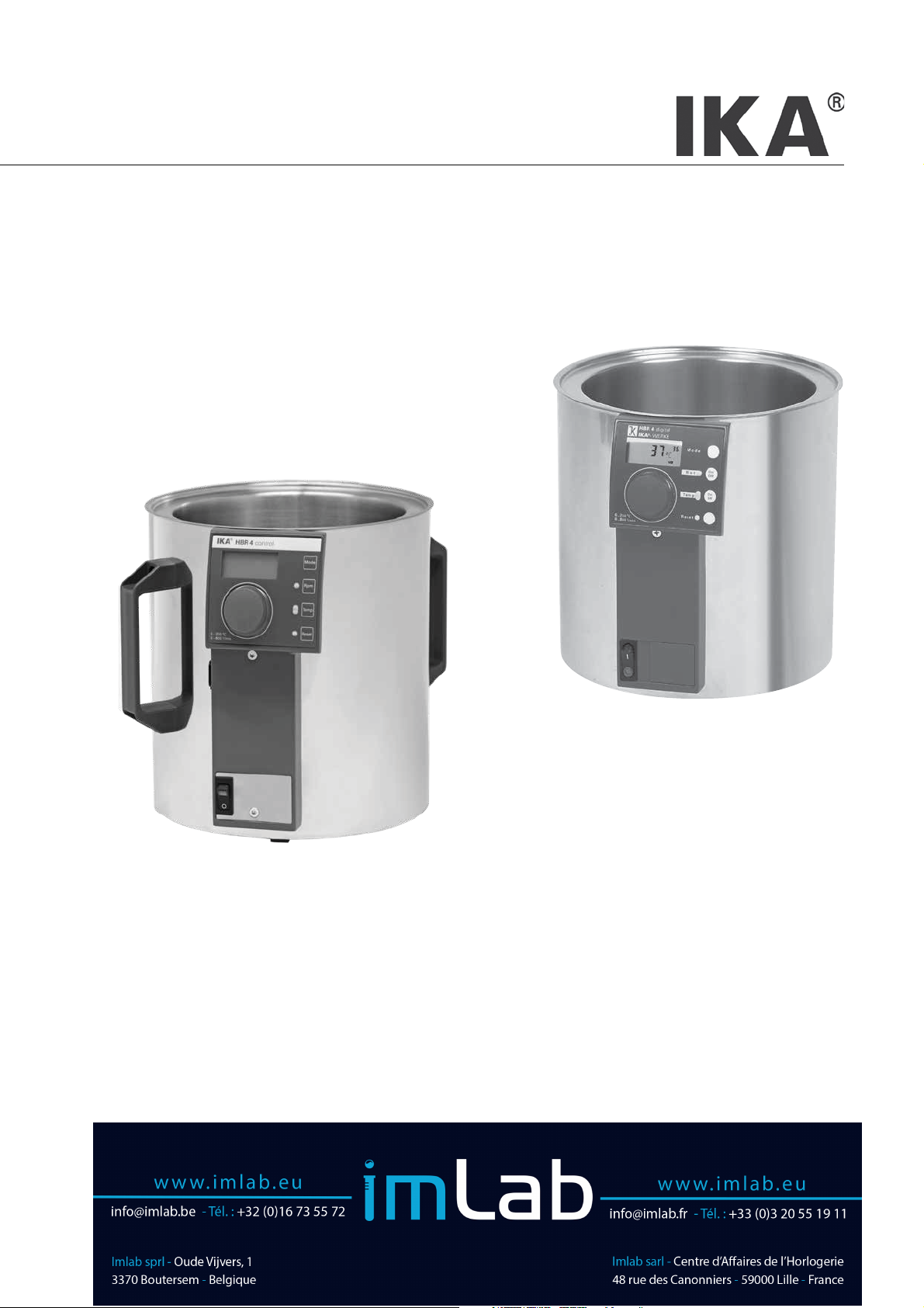
IKA® HBR 4 control
IKA
®
HBR 4 digital
Page 2
Source language: German
EN
Contents
Page
Display and operator panel 2
EU Declaration of conformity
Explication of warning symbols 15
Safety instructions 16
Unpacking 17
Correct use 17
Commissioning 18
Setting the safety circuit 18
Setting the operating modes 18
Heating function 18
Control of medium temperature 19
Operation with external temperature sensor PT 1000.60/61 (only for HBR 4 control) 19
Stirring function 19
Error messages 20
Interfaces and outputs 21
Maintenance and cleaning 24
Accessories 24
Warranty 25
Technical data 25
15
EU Declaration of conformity
We declare under our sole responsibility that this product corresponds to the directives 2014/35/EU, 2014/30/EU and 2011/65/EU and
conforms with the following standards or normative documents: EN 61010-1, EN 61010-2-010, EN 61010-2-051, EN 61326-1, EN
60529 (A1+A2) and EN ISO 12100.
A copy of the complete EU Declaration of Conformity can be requested at sales@ika.com.
Explication of warning symbols
DANGER
WARNING
CAUTION
ATTENTION
Indicates an imminently hazardous situation, which, if not avoided, will result in death, serious injury.
Indicates a potentially hazardous situation, which, if not avoided, can result in death, serious injury.
Indicates a potentially hazardous situation, which, if not avoided, can result in injury.
ATTENTION - risk of damage due to magnetism.
DANGER
DANGER - note on hazards arising from a hot surface.
15
Page 3
Safety instructions
For your protection
• Read the operating instructions in full before starting up
and follow the safety instructions.
• Keep the operating instructions in a place where they can be
accessed by everyone.
Ensure that only trained staff work with the appliance.
•
• Follow the safety instructions, guidelines, occupational health
and safety and accident prevention regulations.
• Wear your personal protective equipment in accordance with
the hazard category of the medium to be processed. Otherwise
there is a risk of splashing liquids.
When emptying the device use only the handles to carry and hold it.
•
• Set up the device in a spacious area on an even, stable, clean,
non-slip, dry and fireproof surface.
• Prior to each use, always check the device and accessories for
damage. Do not use damaged components.
• Caution! Only process and heat up media that has a flash point
higher than the adjusted safe temperature limit of the heating
bath that has been set.
The safe temperature limit of the heating bath must always be
set to at least 25 °C lower than the fire point of the media used.
Risk of burns! During operation,
DANGER
When working with temperature
sensitive mediums please consider: upon continuous operation
with high speed and a room temperature of 20 °C a warming up
of the housing up to 40 °C is possible.
• Prior to filling or emptying the heating bath, the device must be
switched off and disconnected from the power supply at the
plug.
• Only fill or empty the heating bath when it is cold.
• Empty the heating bath prior to transporting it.
• Never operate the heating bath without tempering medium.
DANGER
flash point > 260 °C are also permitted.
There is a risk of burning when using tempering media with low-
er flashpoints!
• Before use, calculate the optimum fill level of the tempering medium! Pay special attention to the change in volume caused by
heating and the displacement that occurs when immersing an
object, for example, an evaporating flask.
• When using the heating bath in conjunction with a rotary evaporator, the heating bath temperature must not be allowed to rise
to a value higher than the boiling point of the solvent at normal
pressure, since if the evaporating flask glass were to break there
would be a hazard due to liquid spraying out (for instance breakage of the evaporating flask glass during distillation of water
using a silicone oil bath).
• When working with the IKA
hazard arising from breakage of the evaporating flask glass.
• Be aware of a hazard due to lack of grip on a wet evaporating
flask, in particular when operating the IKA
control heating bath with silicone oil!
the heating bath housing can get
hot.
Caution! The preferred tempering
medium in the heating bath is water (up to approx. 80 °C). Low viscosity silicone oils (50 mPas) with a
®
rotary evaporator, be aware of a
®
HBR 4 digital/
• When using as a water bath, the use of demineralised water is
recommended.
• Always observe the minimum fill level of one litre when using oil
as the tempering medium.
• Ensure that the interfaces are not soiled.
• Beware of hazards due to flammable materials.
• Only process media that will not react dangerously to the extra
energy produced through processing. This also applies to any
extra energy produced in other ways, e.g. through light irradiation.
• Do not operate the appliance in explosive atmospheres, with
hazardous substances or under water.
• Refer to the operating instructions for the accessories.
• Safe operation is only guaranteed with the accessories described
in the ”Accessories” chapter.
• Always disconnect the plug before fitting accessories.
• After an interruption to the power supply, the device can be
started up again in operating mode B and C.
• The device is only disconnected from the power supply network
if the device power switch is off or the plug is pulled out.
• The socket for the mains cord must be easily accessible.
Caution - magnetism!
ATTENTION
For protection of the equipment
• The voltage stated on the type plate must correspond to the
mains voltage.
Socket must be earthed (protective ground contact).
•
• Protect the appliance and accessories from bumps and impacts.
• The appliance may only be opened by experts.
In conjunction with
• Solvents can be hazardous to health. Therefore comply with the
relevant warnings and refer to the relevant safety data sheet
(Internet).
®
Glassware
IKA
The glassware is designed to be used at vacuums down to 1 mbar.
•
Coated glassware
• Coated glass components offer protection against the glass
splintering if it breaks under vacuum. Please note that when
coated glassware is used it is only to the condenser and receiving flask to which coating is applied.
• For operational reasons, the coating is not applied to the entire
area of the glass. In particular on the condenser there are areas
to which no coating is applied, especially at places where joints
and connections are made.
• Evaporating flasks with special heat-resistant coatings are available as accessories.
• The coating does not offer any protection against damage to
the glass or breakage of the glass.
• Do not use the glass component if its coating is damaged.
• The use of coated glassware does not release you from the obligation when the device is in use to enclose it on all sides with an
extractor hood or to employ an appropriate safety device.
IKA® rotary evaporator,
Beware of possible effects from the
magnetic field (pacemakers, data
media).
IKA® glassware and solvents
16
Page 4

Oil-tempered heating bath
• If silicone oil is used as a tempering medium, in the event that
the evaporating flask fractures there is a risk that on mixing with
the aqueous solvents (contents of the evaporating flask) the hot
oil will foam up and spurt out in conjunction with a rapid increase in volume (formation of bubbles by the solvent).
Note: Using high-viscosity oils or solid grease can lead to over-
heating in localized areas, causing excessive pressure to build up
in the bottom of the vessel.
Unpacking
• Unpacking
- Please unpack the device carefully;
- In the case of any damage a fact report must be set immediately (post, rail or forwarder).
Correct use
• Use
The IKA
devices and are suitable for directly tempering substances filled
into the bath container.
They are also suitable for indirect tempering of substances filled
in glass containers when the glass containers are immersed in the
actual tempering medium. A rotary glass container is particularly
advantageous, for example, when used in conjunction with an
IKA
Do not use the device to prepare food!
®
tempering baths HBR 4 digital/control are laboratory
®
rotary evaporator.
• Delivery scope
Heating bath IKA
®
HBR 4 digital/control
- Heating bath
- Mains cable
- Operating instructions
- Temperature sensor PT 1000.60/61 (only for HBR 4 control)
• Area of use (only indoors)
- Laboratories - Schools
- Pharmacies - Universities
The device is suitable for use in all areas apart from:
- domestic areas
- areas directly connected to a low-voltage supply which also
serves domestic areas.
The safety of the user cannot be guaranteed:
- if the device is used in conjunction with accessories which are
not supplied or recommended by the manufacturer;
if the device is used contrary to the intended purpose against the
manufacturer’s instructions;
- if the device itself or PCB has been subjected to modifications by
the third parties.
17
Page 5

Commissioning
Observe the ambient conditions (temperature, humidity, etc.) listed
under Technical Data.
The unit is ready for service when
the mains plug has been plugged
in.
Please follow above directions to ensure safe operation and prevent device from suffering damage.
Setting the safety circuit
When activating the HBR 4 control devices an automatic self-test
is carried out, all LEDs flash and all segments (Fig. 1) are visible on
the LCD display. After this, the LCD displays in Fig. 2 to Fig. 6 are
visible (standard factory setting).
When setting the safety circuit an upper temperature limit between 50 °C and 210 °C is set. The safety circuit can only be set
in operating mode A.
Switch on the device.
•
The device is switched on with the 2-pole ON/OFF mains switch (A).
When switched on the lamp in the rocker switch lights up green.
Within 5 seconds of the display
•
D
ton “Mode” (
desir
ed by simultaneously turning the control knob (
• Release the button “Mode” (
perature is set and safe OK Fig. 8 is displayed; the safety tem-
e set is saved.
peratur
The safety cir
restarted.
) pressed down and set the safety temperature
cuit is automatically checked each time the device is
Fig. 7
appearing, keep the but-
B
).
D
). For two seconds the safety tem-
Setting the operating modes
The device can be operated in three different operating modes
(display see Fig. 9 to Fig. 11). To toggle from one operating mode
to the other keep the button “Mode” (
ing on the device (min. 5 secs). Sequence A-B-C-A-B-C-A- etc.
Operating mode A
This operating mode is the factory setting of the device. When
switching on the device the heating and stirring functions are deactivated. The set values last set are saved and are used when the
heating or stirring functions are switched on. The set values can
be changed.
D
) depressed when switch-
Heating function
With the button “Mode” (D) the correcting variable desired (set
temperature) can be preselected. The heating bath temperature of
the device is kept constant by the control circuit and is additionally
monitored by the safety circuit. In the event of a disturbance in
the control circuit, the heating bath is switched off permanently
by the safety circuit. In the event of a fault in the control circuit
or in the safety circuit, the LED “Temp.” flashes yellow and green
alternately. The LED next to the reset button lights up red.
Operating mode B
When switching on the device the state of the heating and stirring
functions are taken over before the device was switched off last as
well as the last values set. The set values can be changed.
Operating mode C
When switching on the device the state of the heating and stirring
functions are taken over before the device was switched off last
as well as the last values set. The set values cannot be changed.
The error is also displayed on the LCD (see chapter “Error messages”).
The heating function cannot be started.
18
Page 6

Control of medium temperature
The desired medium temperature can be set between 0 and 200
°C with the control knob (B), but not higher than the set safety
temperature. The value set can be read off on the digital display
(C) (Fig. 12). The heating function is switched on and off by pressing the button “Temp. On/Off” (F). If this function is activated the
green LED next to the lettering “Temp” lights up. The heating bath
is heated up to the set temperature. On the LCD display the set
temperature, actual temperature and the PV symbol are displayed.
The set temperature and actual temperature relate to the medium. During the heating phase the colour of the LED changes
between green and yellow. If the yellow LED lights up this means
that the heating system is being supplied with energy. If the heating function is switched off using the sensor key and the medium
has reached a temperature of above 50 °C the yellow LED flashes
(20% on 80% off).
On the LCD display °C and HOT are displayed alternately (Fig. 13
and 14). The temperature of the heating element is limited by the
safety temperature set. The medium temperature is controlled by
a fuzzy logic controller. The medium temperature is measured by
a PT 500 temperature sensor and is heated up as quickly as possible without overshooting to the set temperature. The fuzzy logic
controller automatically adapts to the various heat capacities of
the different heat transfer fluids. This guarantees an optimal temperature management without temperature drift and waviness.
Operation with external temperature sensor PT 1000.60/61 (only for HBR 4 control)
The supplied external temperature sensor PT 1000.60/61 can be
used as a setpoint transmitter for controlling the temperature of
media, by using a vessel (e.g. glass flask) which is immersed in the
water or oil bath.
The sensor tube must be of sucient length to be immersed in
the medium to be tempered (at least 20 mm) and fixed in position
on the vessel.
If the temperature sensor PT 1000.60/61 is connected to
the interface, the temperature regulation is automatically
controlled by the external sensor!
The temperature sensor PT 1000.60/61 is not intended to act as a
temperature sensor for the heating bath.
If the sensor is immersed directly in the heating bath (which is
considered misuse) and is at the bottom of the bath, control deviations of up to +/-4 K can occur.
An error message (Er 5) will appear if the sensor value of the external sensor does not change within a certain period of time (adjustable Error 5 response time 1 ... 30 min), e.g., because the sensor is
not immersed in the medium.
This detection is activated only at differences > 5 K between the sensor temperature and the target temperature,
when the sensor temperature remains constant (+/- 0.5 K).
Setting the response time of error 5:
When “Er 5” appears on the display, press and hold the button
“Mode” (D) and at the same time set the desired response time
(1...30 min) by turning the control knob (B) .
Note:
0 min (zero) means the monitoring is switched off (OFF)!
Stirring function
With the button ”Mode” (D) the correcting variable desired (set
speed) can be preselected. With the control knob (B) the desired
speed of the stirrer drive can be set between 0 and 800 rpm in
steps of 50 rpm. The value set can be read off on the digital display
(C) (Fig. 15).
The stirring function is switched on and off by pressing the button “Motor On/Off” (E). If this function is activated the green LED
lights up next to the lettering “Mot.“ The motor runs gently up to
the speed set. On the LCD display the set speed, actual speed and
the PV symbol are displayed (Fig. 16).
If both functions (heating and stirring) are switched off, the LCD
display always indicates the set temperature set. When the heating
function is switched on it is given priority on the LCD display.
If the stirring function is started with the sensor key or called up
using the button ”Mode” (D), the system switches over to speed
display for five seconds. With the button ”Mode” (D) the LCD display can be changed from temperature to speed and vice versa
at any time. After five seconds the system switches back to the
predominant mode.
19
Page 7

Error messages
The following error messages can be displayed (Fig. 20) and have the following causes described:
Error code Cause Correction
Er 2 In remote operation (PC) mode with activated
watchdog function in mode 1: no communication
between PC and HBR 4 control. PC does not
transmit any data within the set watchdog time, or
connection to PC is interrupted.
Er 3 Internal device temperature above 76 °C Allow the device to cool down
Er 4
Er 4
Er 5 No temperature increase in PT 1000.60/61 at con-
Er 11 Temperature sensor PT 1000 unplugged during
Er 12 Temperature sensor PT 1000 plugged in during
Er 20 Safety relay does not close Safety circuit is set too low, check mains voltage (mains voltage
Er 21 Safety relay does not open RESETbutton / service
Er 22 Disturbance before the last time the device was
Er 23 Adjustable safety circuit faulty Mains switch OFF/ON / service
Er 24 Safety temperature set exceeded Set safety temperature higher
Er 26 System dry, no medium in the bath container Allow the device to cool down, then refill with medium.
Er 27 Calibration error Mains switch OFF/ON. When switching on, a calibration is auto-
Er 28 Sensor rupture Mains switch OFF/ON
Er 29 Short circuit in the safety sensor or controller and
Er 30 Short circuit in the controller sensor Service
Motor speed deviates ±300 rpm from the speed
Set speed greater than 350 rpm
Stirring function turned on, Actual speed = 0 rpm
Indication after approx 30 sec
tinuous temperature difference (corresponding to
the set error 5 response time)
operation
operation
switched OFF or safety temperature is lower then
the temperature of the medium
safety sensor mixed up
Change watchdog time.
Transmit data from PC within set watchdog time (OUT_WDx@m).
Check cable and plug.
Mains switch OFF/ON
Reduce load
Mains switch OFF/ON
Mains switch OFF/ON
Increase the speed or turn on the stirring function
Place the temperature sensor in the medium.
Adjust the error 5 response time according to the response characteristic of the system.
Plug in and unplug temperature sensor only when HBR 4 control
is switched off.
Plug in and unplug temperature sensor only when HBR 4 control
is switched off.
must be larger than the nominal voltage - 10%).
Mains switch OFF/ON
RESET button
Mains switch OFF/ON
Mains switch OFF/ON
matically carried out.
Service
If the actions described fail to resolve the fault or another error code is displayed then take one of the following steps:
- contact the IKA
- send the device for repair, including a short description of the fault.
®
service department,
20
Page 8

Interfaces and outputs
The device can be operated in “Remote” mode via an RS 232 using
the laboratory software Labworldsoft
®
.
Note: Please comply with the system requirements together with
the operating instructions and help section included with the software.
Configuration
The RS 232 serial interface can be used to operate the device using
a computer and a suitable user program (Labworldsoft
®
).
In order to increase safety when operating the HBR 4 control
using a PC, a watchdog function can be activated which monitors
the continuous data flow (see section entitled: “Watchdog function”).
• The functions of the interface circuit between the laboratory de-
vice and the automation system are a selection from the signals
specified in the EIA standard RS 232 C as per DIN 66020 Part 1.
The assignment of the different signals can be seen in the image.
• Standard RS 232 C, corresponding to DIN 66259 Part 1 is valid
for the electronic characteristics of the interface circuits and assignment of signal states.
• Transmission process: asynchronous character transmission in
start-stop operation.
• Transmission type: full duplex
• Character format: character composition according to data for-
mat in DIN 66022 for start-stop operation. 1 start bit, 7 character bits, 1 parity bit (even), 1 stop bit.
• Transmission speed: 9600 bit/s
• Data flow control: hardware handshake
• Access method: data transmission from the device to the com-
puter only occurs after a request from the computer.
Command syntax
The following points should be noted for the instruction set:
• Commands are generally sent from the computer (master) to the
lab device (slave).
• The device sends only at the computer’s request. Even fault indications cannot be sent spontaneously from the device to the
computer (automation system).
• Commands and parameters, as well as consecutive parameters,
must be separated by at least one space (code: hex0x20).
• Each individual command (incl. parameters and data) and each
response are terminated with Blank CR LF (Code: hex 0x0D and
0x0A) and have a maximum length of 80 characters.
• The decimal separator in a number is a dot (Code: hex 0x2E).
The above details correspond as far as possible to the recommendations of the NAMUR working party (NAMUR recommendations
for the design of electrical plug connections for analogue and
digital signal transmission on individual items of laboratory control
equipment, rev. 1.1).
Summary of available NAMUR commands
Abbreviations used:
X,y =
numbering parameter (integer)
m = variable value, integer
n = variable value, floating-point number
X = 1 Temperature of external sensor
X = 2 Bath temperature
X = 3 Bath safety temperature
X = 4 Speed
X = 52 External PT 1000 temperature sensor offset in K (-3.0 <= n <=+3.0 )
X = 54 Error 5 response time in minutes (1 <= n <= 30)
21
Page 9

NAMUR commands Function Display
(additional)
IN_NAME Title request
IN_PV_X X=1;2;3;4;; Current value reading
IN_SOFTWARE Software ID number, date, version request
IN_SP_X X=1;2;3;4;12;42
52;54;
IN_TYPE Lab device identification request
OUT_NAME name Output of identification name. (Max. 6 characters; default: IKAHBR)
OUT_SP_12@n Setting WD safety limit temperature with set value echo
OUT_SP_42@n Setting WD safety limit speed with set value echo
OUT_SP_X n X=1;2;4;52; 54; Setting of target value to n
OUT_WD1@m Watchdog mode 1: if event WD1 should occur, the heating and stirring func-
OUT_WD2@m Watchdog mode 2: if event WD2 should occur, the speed target value is
RESET Switches off the device function.
RMP_CONT_X X=1;4 Continuaton of ramp function (After prior RMP_PAUSE_X).
RMP_IN_X X=1;4 Reading the real segment number of ramp. With ramp not started: 0
RMP_IN_X_y X=1;4 Reading the accumulated value and the ramp segment duration of ramp seg-
RMP_LOOP_SET_X X=1;4 Ending of ramp loop.
RMP_LOOP_RESET_X X=1;4 To work off the ramps in one loop.
RMP_OUT_X_y n
hh:mm:ss
RMP_PAUSE_X X=1;4 Stopping the ramp function. Freezing of real rated value and real ramp seg-
RMP_RESET_X Switching off ramp functions and deleting of all set ramp segments
RMP_START_X X=1;4 Starting the ramp function, beginning with ramp function No.1 (Only possible
RMP_STOP_X X=1;4 Switching off ramp function. Rated value = 0. (Ramp is maintained, that
START_X X=1;2;4;5;7 Starting the instrument’s (remote) function. Remote
X=1;4 Setting the accumulated value (n) and the ramp segment duration (hh:mm:ss)
Set target value reading
tions are switched off and ER 2 is displayed. Set watchdog time to m (20
- 1,500) seconds, with watchdog time echo. This command launches the
watchdog function and must be transmitted within the set watchdog time.
changed to the WD safety speed limit and the temperature target value is
changed to the WD safety temperature limit value. The warning WD is displayed. The WD2 event can be reset with OUT_WD2@0 - this also stops
the watchdog function. Set watchdog time to m (20 - 1,500) seconds, with
watchdog time echo. This command launches the watchdog function and
must be transmitted within the set watchdog time.
ment y.
for ramp segment y.
ment time.
after prior START_X. After RMP_STOP_X START_X is not necessary.)
means, ramp can be restarted with RMP_STARTX_X).
22
Page 10

STATUS_X X=1;4;5
X=16
(old function)
Display of status
1*: Operation mode A
2*: Operation mode B
3*: Operation mode C
*0: manual operation without fault
*1: Automatic operation Start (without fault)
*2: Automatic operation Start (without fault)
<0: Error code: (-1)
- 1: Error 1
- ... (see table)
- 31:Error 31
-83: wrong parity
-84: unknown instruction
-85: wrong instruction sequence
-86: invalid rated value
-87: not sucient storage space
STOP_X X=1;2;4;5;7 Switching off of device - (remote) function The variables set with OUT_SP_X
Remote
remain saved. Includes command RMP_STOP.
“Watchdog” functions; monitoring of the serial data flow
If, once this function has been activated (see NAMUR commands), there is no retransmission of the command from the computer within
the set time (“watchdog time”), the heating and stirring functions are switched off in accordance with the set “watchdog” function or
are changed to the set target values.
The data transmission may be interrupted by, for example, a crash in the operating system, a power failure in the PC or an issue with the
connection cable between the computer and the device.
“Watchdog” - mode 1
If there is an interruption in data communications (longer than the set watchdog time), the heating and stirring functions are switched
off and ER 2 is displayed.
“Watchdog” - mode 2
If there is an interruption in data communications (longer than the set watchdog time), the speed target value is changed to the WD
safety speed limit and the temperature target value is changed to the WD safety temperature limit value. The warning WD is displayed.
PC 2.1 cable
The PC 2.1 cable is used to connect the 9-pin plug to a computer.
6
7
8
9
1
2
3
4
5
1
RxD 2
TxD 3
4
GND 5
6
RTS 7
CTS 8
9
1
2 RxD
3 TxD
4
5 GND
6
7 RTS
8 CTS
9
9
8
7
6
PC
5
4
3
2
1
23
Page 11

Maintenance and cleaning
The safety circuit must be checked over at least once a year by the
user. To do this, fill the temperature control bath with 1 l of water and in operating mode A set the safety temperature to 100
°C. Then set the target temperature to 80 °C and start the heating function by pressing the Temp ON/OFF key. After the target
temperature has been reached, switch the moderating bath off
and back on again with the power switch and set the safety temperature to 70 °C. The temperature of the medium will then be
10 °C above the safety temperature, and the safety circuit will be
activated. Error message Er 22 or Er 24 must be displayed.
The device is maintenance-free. It is subject only to the natural
wear and tear of components and their statistical failure rate.
Cleaning:
Remove the device from the
mains before cleaning.
®
Only use cleaning materials recommended by IKA
:
Dirt Cleaning agent
Dyes Isopropyl alcohol
Building materials
Cosmetics
Water containing detergent/isopropyl alcohol
Water containing detergent/isopropyl alcohol
Food Water containing detergent
Fuels Water containing detergent
Other materials Please consult IKA
®
Before using another than the recommended method for cleaning
or decontamination, the user must ascertain with the manufacturer that this method does not destroy the instrument.
Ordering spare parts:
When ordering spare parts, please make sure to indicate the following:
- device type
- device serial number, see rating plate
- position number and description of spare part, see
www.ika.com
- software version.
Repairs:
Please only send devices in for repair that have been cleaned
and are free of materials which might present health hazards.
For this, use the “Decontamination Certificate” form which
you can obtain from IKA
from the IKA
®
website at www.ika.com.
®
or can download a version for printing
If your appliance requires repair, return it in its original packaging.
Storage packaging is not sucient when sending the device - also
use appropriate transport packaging.
Wear the proper protective gloves during cleaning of the devices.
Electrical devices may not be placed in the cleansing agent for the
purpose of cleaning.
Do not allow moisture to get into the equipment when cleaning.
Accessories
H 210 Ring set
H 159 Intermediate bottom
H 162 Set of test tubes
H 160 Cover
IKAFLON stirring bar, ø7x60 mm
PC 2.1 Connecting cable
Software IKA
®
Labworldsoft
®
24
Page 12

Warranty
According to IKA®’s Terms and Conditions of sale and delivery,
this product is covered by a warranty for a period of 24 months. In
case of making a warranty claim, please contact your local dealer
or, if you wish, you can send the device directly to our factory.
Please include the sales invoice and state the reasons for your
guarantee claim. In this case, you are responsible for shipping and
handling costs.
The warranty does not cover wearing parts, nor to defects that are
the result of improper use, insucient care and maintenance or
failure to follow the instructions in this operating manual.
Technical data
HBR 4 control HBR 4 digital
Nominal voltage
or
Frequency Hz 50/60
Heating function
Heating output W 1000
Temperature range (medium) °C Room temperature...200
Temperature range (medium) Set and actual temperature LCD
Setting accuracy K 11
Controller deviation (3 l water/90 °C) K ± 0.4 ± 0.4
Absolute deviation / mean (3 l water/90 °C) K ± 1 ± 1
Controller deviation (3 l Marlotherm oil/150 °C) K ± 0.8 ± 0.8
Absolute deviation / mean (3 l Marlotherm oil/150 °C) K ± 2 ± 2
Stirring function
Motor Ballbearing brush-free, EC motor
Motor output W 55
Speed range rpm 150...800 adjustable in steps of 50 rpm
Minimum filling height cm 33
Overvoltage class II
Permissible operating time % 100
Protection class according to DIN EN 60529 IP 20
Permissible ambient temperature °C +5...40
Permissible relative humidity % 80
Class designation acc. DIN 12876 II
Total volume - bath container l 55
Material - bath container 1.4301
Dimensions (Ø x H) mm 340 x 250 340 x 250
Weight kg 4.4 4.4
Interfaces PT 1000.60/61
VA
VAC
C
RS 232
230 ± 10%
115 ± 10%
-
Subject to technical changes!
25
 Loading...