

Page 1
User Manual
Edition: 2014-04-15
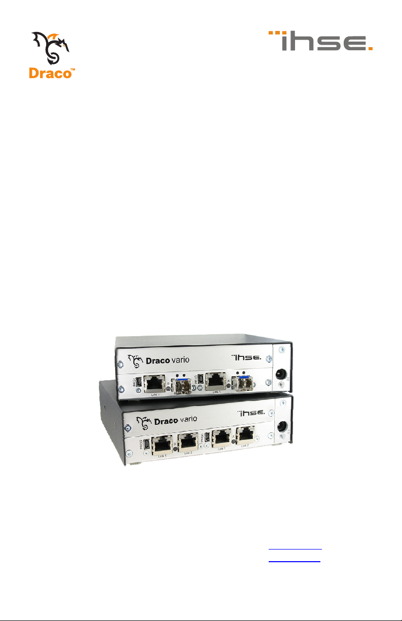
Draco
(Cross) Repeater
Model:
485 Series
IHSE GmbH
Maybachstrasse 11
88094 Oberteuringen
Germany
[email protected]
www.ihse.de
Tel. +49 7546-9248-0
Fax +49 7546-9248-48
Page 2

Draco (Cross) Repeater
Copyright
© 2014. All rights reserved. This information may not be reproduced in any
manner without the prior written consent of the manufacturer.
Information in this document is subject to change without notice.
Trademarks
All trademark and trade names mentioned in this document are
acknowledged to be the property of their respective owners.
Disclaimer
While every precaution has been taken during preparation of this manual,
the manufacturer assumes no liability for errors or omissions. The
manufacturer assumes no liability for damages resulting from the use of
the information contained herein.
The manufacturer reserves the right to change specifications, functions, or
circuitry of the product without notice.
The manufacturer cannot accept liability for damage due to misuse of the
product or due to any other circumstances outside the manufacturer’s
control (whether environmental or installation related). The manufacturer
shall not be liable for any loss, damage, or injury arising directly, indirectly,
incidentally, or consequently from the use of this product.
2 2014-04-15
Page 3

Contents
Contents
1 About This Manual ....................................................................... 5
1.1 Scope.................................................................................. 5
1.2 Validity ................................................................................ 5
1.3 Cautions and Notes ............................................................ 5
2 Safety Instructions....................................................................... 6
3 Description ................................................................................... 7
3.1 Application .......................................................................... 7
3.2 System Overview ................................................................ 8
3.3 Product Range .................................................................... 9
3.3.1 Chassis ................................................................. 9
3.3.2 (Cross) Repeater Modules .................................. 10
3.4 Accessories Upgrade Kits ................................................. 10
3.5 Accessories....................................................................... 11
3.6 Device Views .................................................................... 11
3.6.1 2-fold Vario Chassis 474-BODY2/2R .................. 11
3.6.2 2-fold Vario Chassis 474-BODY2N ..................... 12
3.6.3 4-fold Vario Chassis 474-BODY4/4R .................. 13
3.6.4 6-fold Vario Chassis 474-BODY6R ..................... 14
3.6.5 6-fold Vario Chassis 474-BODY6BP................... 15
3.6.6 6-fold Vario Chassis 474-BODY6BPF................. 16
3.6.7 21-fold Vario Chassis 474-BODY21R ................. 17
3.6.8 Model 485-BC ..................................................... 18
3.6.9 Model 485-BS ..................................................... 18
3.6.10 Model 485-BX ..................................................... 18
3.6.11 Model 485-BCC .................................................. 19
3.6.12 Model 485-BSS................................................... 19
3.6.13 Model 485-BXX................................................... 20
3.7 Status LEDs ...................................................................... 21
3.7.1 Status (Cross) Repeater Module......................... 21
2014-04-15 3
Page 4

Draco (Cross) Repeater
4 Installation .................................................................................. 22
4.1 Package Contents............................................................. 22
4.2 System anschließen.......................................................... 22
4.2.1 (Cross) Repeater Setup ...................................... 22
4.3 Example Applications........................................................ 23
5 Configuration.............................................................................. 25
6 Operation .................................................................................... 25
7 Specifications............................................................................. 26
7.1 Interfaces .......................................................................... 26
7.1.1 RJ45 (Interconnect) ............................................ 26
7.1.2 Fiber SFP Type LC (Interconnect) ...................... 26
7.2 Interconnect Cable............................................................ 27
7.2.1 Cat X ................................................................... 27
7.2.2 Fiber.................................................................... 28
7.3 Connector Pinouts ............................................................ 29
7.4 Power Supply.................................................................... 30
7.5 Environmental Conditions ................................................. 30
7.6 Size................................................................................... 31
7.7 Shipping Weight................................................................ 32
8 Troubleshooting......................................................................... 33
8.1 General Failures ............................................................... 33
9 Technical Support ...................................................................... 34
9.1 Support Checklist.............................................................. 34
9.2 Shipping Checklist ............................................................ 34
10 Certificates.................................................................................. 35
10.1 CE Declaration Of Conformity........................................... 35
10.2 North American Regulatory Compliance........................... 36
10.3 Product Safety .................................................................. 36
10.4 WEEE ............................................................................... 37
10.5 RoHS/RoHS 2................................................................... 37
11 Glossary...................................................................................... 38
Pos: 1 /806-IHSE/Zu diesem Handbuch/ATB_Zu diesem Handbuc h @ 5\mod_1278573163276_6. doc @ 41510 @ 1222 @ 1
4 2014-04-15
Page 5
About This Manual
1 About This Manual
1.1 Scope
This manual describes how to install your (Cross) Repeater, how to
operate it and how to perform trouble shooting.
1.2 Validity
This manual is valid for all devices listed on the front page. The product
code is printed on the base of the devices.
1.3 Cautions and Notes
The following symbols are used in this manual:
This symbol indicates an important operating instruction that should be
followed to avoid any potential damage to hardware or property, loss of
data, or personal injury.
This symbol indicates important information to help you make the best use
of this product.
This symbol indicates best practice information to show recommended
and optimal ways to use this product in an efficient way.
Pos: 2 /806-IHSE/Sicherheitshinweise/ATB_Sic herheitshinweise @ 5\m od_1278573321245_6. doc @ 41528 @ 1 @ 1
2014-04-15 5
Page 6

Draco (Cross) Repeater
2 Safety Instructions
To ensure reliable and safe long-term operation of your (Cross) Repeater
please note the following guidelines:
Installation
Only use in dry, indoor environments.
The (Cross) Repeater and the power supply units can get warm. Do
not install components in an enclosed space without any airflow.
Do not place the power supply directly on top of the device.
Do not obscure ventilation holes.
Only use power supplies originally supplied with the product or
manufacturer-approved replacements. Do not use a power supply if it
appears to be defective or has a damaged chassis.
Connect all power supplies to grounded outlets. In each case, ensure
that the ground connection is maintained from the outlet socket
through to the power supply's AC power input.
Do not connect the link interface to any other equipment, particularly
network or telecommunications equipment.
Take any required ESD precautions.
In order to disconnect the device completely from the electric circuit, all
power cables have to be removed.
Repair
Do not attempt to open or repair a power supply unit.
Do not attempt to open or repair the (Cross) Repeater. There are no
user serviceable parts inside.
Please contact your dealer or manufacturer if there is a fault.
Pos: 3 /806-IHSE/Beschreibung/UEB_Beschreibung @ 5\ mod_1278573379151_6. doc @ 41546 @ 1 @ 1
6 2014-04-15
Page 7

Description
3 Description
Pos: 4 /806-IHSE/Beschreibung/Verwendungszweck/ 485-xx @ 11\mod_139514 5109102_6.doc @ 140748 @ 2 @ 1
3.1 Application
The (Cross) Repeater is basically used in order to double the maximum
cabling distance between a KVM extender CON or CPU Unit or even a
KVM matrix. In addition to that the device can also be used for media
conversion from Cat X to fiber or vice versa.
The device is available as a pure Cat X or fiber version (repeater) and as
a hybrid version of Cat X and fiber (cross repeater) for an additional
electrical/optical signal conversion.
Pos: 5 /806-IHSE/Beschreibung/System-Übersic ht /485-xx @ 11\mod_139514 5337503_6.doc @ 140779 @ 2 @ 1
2014-04-15 7
Page 8
Draco (Cross) Repeater
3.2 System Overview
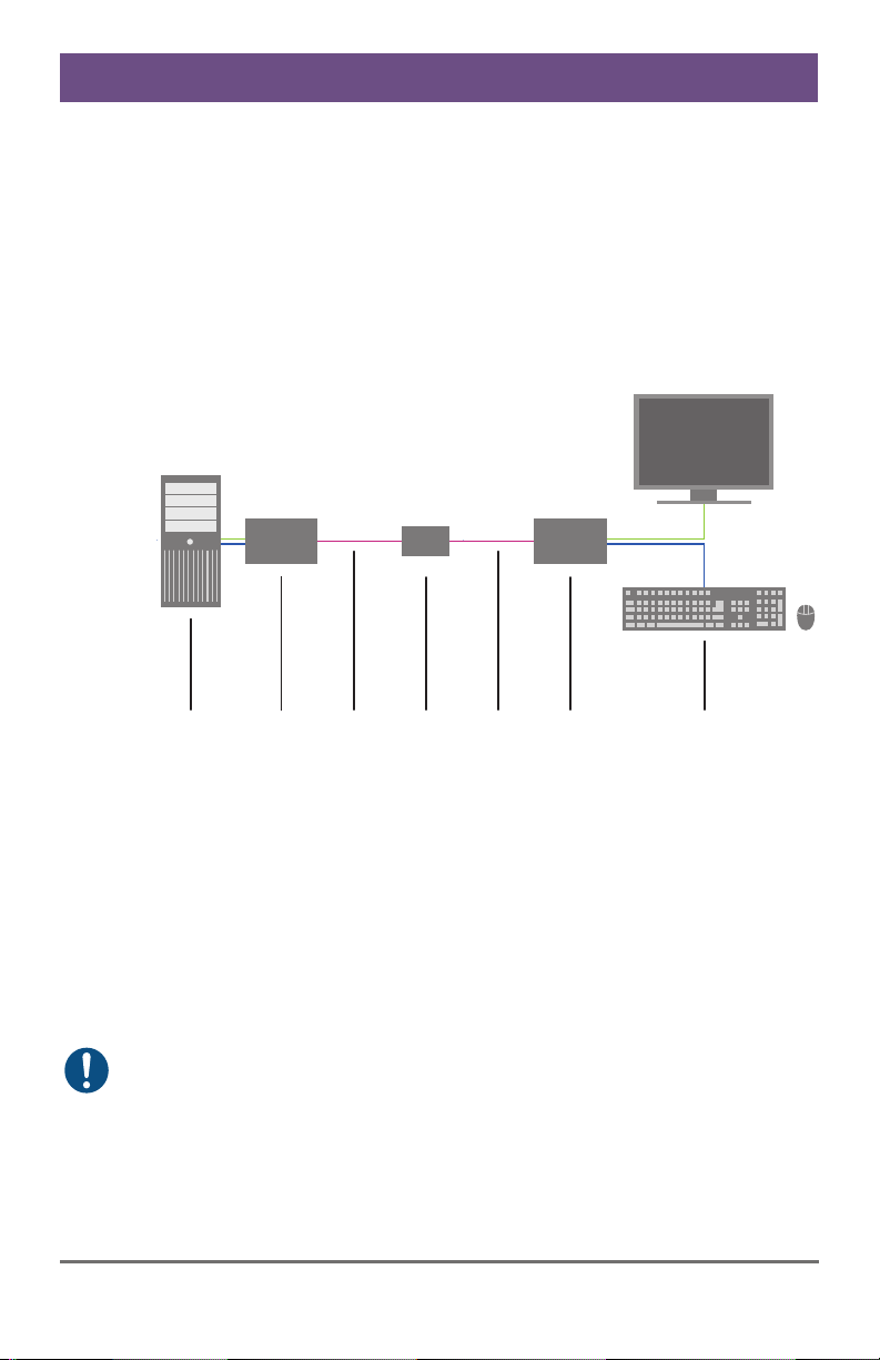
The (Cross) Repeater consists of at least one module depending on the
application.
The device is connected between a KVM extender CON and CPU Unit via
the interconnect cable or can be alternatively connected between a KVM
extender unit and a KVM matrix.
The (Cross) Repeater communicates with both the KVM extenders and a
KVM-Matrix via the interconnect cables.
1 2 4 53 761 2 4 53 76
System Overview
1 Source (computer, CPU)
2 KVM Extender CPU Unit
3 Interconnect cable (Cat X or fiber)
4 (Cross) Repeater
5 Interconnect cable (Cat X or fiber)
6 KVM Extender CON Unit
7 Console (monitor, keyboard, mouse)
See Chapter 4.3, Page 23 for installation examples.
Pos: 6 /806-IHSE/Beschreibung/Gerätetypen/485- xx @ 11\mod_13951456414 36_6.doc @ 140805 @ 233 @ 1
8 2014-04-15
Page 9
Description
3.3 Product Range
3.3.1 Chassis
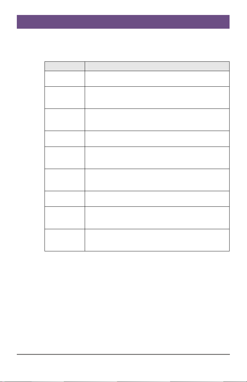
Model Description
474-BODY2
474-BODY2R
474-BODY2N
474-BODY4
474-BODY4R
474-BODY6R
474BODY6BP
474BODY6BPF
474BODY21/4U
Empty chassis for up to 2 boards, 1x external power
supply unit
Empty chassis for up to 2 boards, 1x external power
supply unit, preparation for redundancy for a second
power supply unit (external)
Empty chassis for up to 2 boards, 1x internal power
supply unit, preparation for redundancy for a second
power supply unit (external)
Empty chassis for up to 4 boards, 1x external power
supply unit
Empty chassis for up to 4 boards, 1x external power
supply unit, preparation for redundancy for a second
power supply unit (external)
Empty chassis for up to 6 boards, 1x internal power
supply unit, preparation for redundancy for a second
power supply unit (external)
Empty chassis for up to 6 boards, active backplane, 2x
internal power supply unit (redundancy)
Empty chassis for up to 6 boards, active backplane, 2x
internal power supply unit (redundancy) with connectors
on rear side
Empty chassis for up to 21 boards, 1x internal power
supply unit, preparation for redundancy for a second
power supply unit (internal)
2014-04-15 9
Page 10
Draco (Cross) Repeater
3.3.2 (Cross) Repeater Modules
Model Description
485-BC Repeater module Cat X for range extension up to 280 m
485-BS
Repeater module fiber (Single-Mode) for range
extension up to 20,000 m
485-BX
Repeater module Cat X/fiber (Single-Mode) for an
electrical/optical media conversion, maximum extension
10,140 m
485-BCC
Dual repeater module Cat X for range extension up to
280 m
485-BSS
Dual repeater module fiber (Single-Mode) for range
extension up to 20,000 m
485-BXX
Repeater module Cat X/fiber (Single-Mode) for an
electrical/optical media conversion, maximum extension
Pos: 7 /806-IHSE/Beschreibung/Einbauoptionen/ 474-xx @ 6\mod_13045800 08551_6.doc @ 50839 @ 2 @ 1
10,140 m
3.4 Accessories Upgrade Kits
Model Description
474-2RMK 19"/1U rack mount kit for 2-fold chassis
474-
2NRMK
474-4RMK 19"/1U rack mount kit for 4-fold chassis
474-6RMK 19"/1U rack mount kit for 6-fold chassis
474-
VPLATE
474-
OPTRED
474-PSU2 Power supply for 2-fold chassis (spare or redundancy)
474-PSU4 Power supply for 4-fold chassis (spare or redundancy)
474-PSU6 Power supply for 6-fold chassis (spare or redundancy)
474-PSU21 Power supply for 6-fold-chassis (spare or redundancy)
474-BLND1 Blind plate 3U/4HP for 2-, 4- and 6-fold chassis
474-BLND2 Blind plate 3U/8HP for 2-, 4- and 6-fold chassis
19"/1U rack mount kit for 2-fold chassis with internal PSU
Fastening strips for screw or snap on for 2-, 4- and 6-fold
chassis
Retrofitting for redundant power supply option (without
power supply) for 2- and 4-fold chassis
10 2014-04-15
Page 11
Description
(Cross) Repeaters and the power supply units can get warm and must not
be installed in closed rooms with no air circulation. For rack-mount
installations, at least 0.5 U (height unit) is required above the (Cross)
Pos: 8 /806-IHSE/Beschreibung/Zubehör/485-xx @ 11\ mod_1395145995119_ 6.doc @ 140842 @ 2 @ 1
Repeater for ventilation.
3.5 Accessories
Model Description
260-5G International power supply unit 100...240 VAC / 5 VDC / 3 A
260-5U International power supply unit 100...240 VAC / 5 VDC / 4 A
474-
IEC connection cable for power supply, lockable
PSULOCK
Pos: 9 /806-IHSE/Beschreibung/Geräteansichten/ UEB_Geräteansic hten @ 5\mod_12785737378 08_6.doc @ 41654 @ 2 @ 1
3.6 Device Views
Pos: 10 /806-IHSE/Beschreibung/Geräteansichte n/474-xx/2-fac h Vario-Gehäuse 474-BODY2/ 2R @ 6\mod_130458028056 6_6.doc @ 50858 @ 3 @ 1
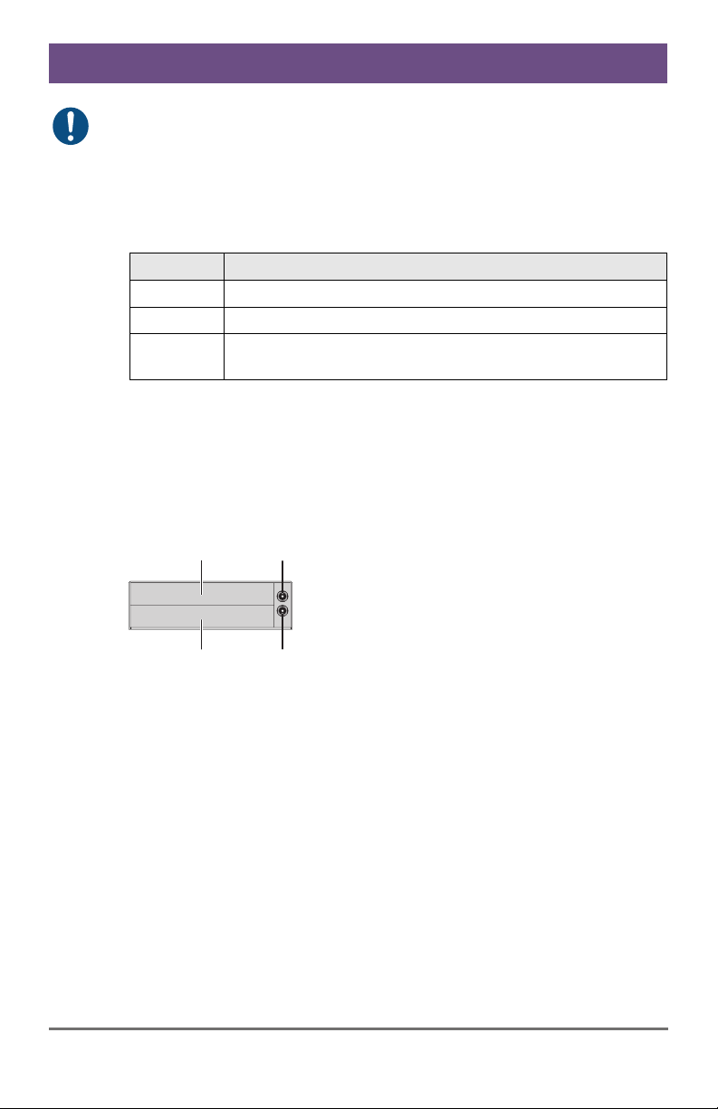
3.6.1 2-fold Vario Chassis 474-BODY2/2R
CPU and CON Unit
3
1
4
2
Rear View
1 Slot for modules #1
2 Connect to 5VDC power supply (standard)
3 Slot for modules #2
4 Connect to 5VDC power supply (redundancy, optional)
Pos: 11 /806-IHSE/Beschreibung/Geräteansichte n/474-xx/2-fac h Vario-Gehäuse 474-BODY2 N @ 8\mod_1348578478411_6. doc @ 69380 @ 3 @ 1
2014-04-15 11
Page 12
Draco (Cross) Repeater
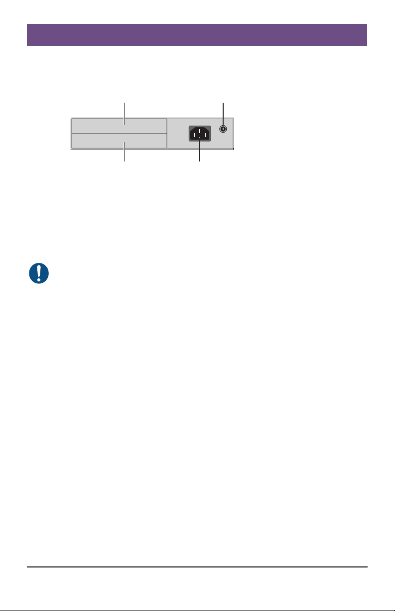
3.6.2 2-fold Vario Chassis 474-BODY2N
CPU and CON Unit
3
4
Rear View
1 Slot for modules #1
2 Connect to power supply (standard)
3 Slot for modules #2
4 Connect to 5VDC power supply (redundancy)
The 2-fold vario chassis with an internal power supply is not equipped with
a fuse on its primary side. Therefore the protection against excessive
currents has to be provided by the electrical installation of the building.
Pos: 12 /806-IHSE/Beschreibung/Geräteansichte n/474-xx/4-fac h Vario-Gehäuse 474-BODY4/ 4R @ 6\mod_130458035909 8_6.doc @ 50876 @ 3 @ 1
1
2
12 2014-04-15
Page 13
Description
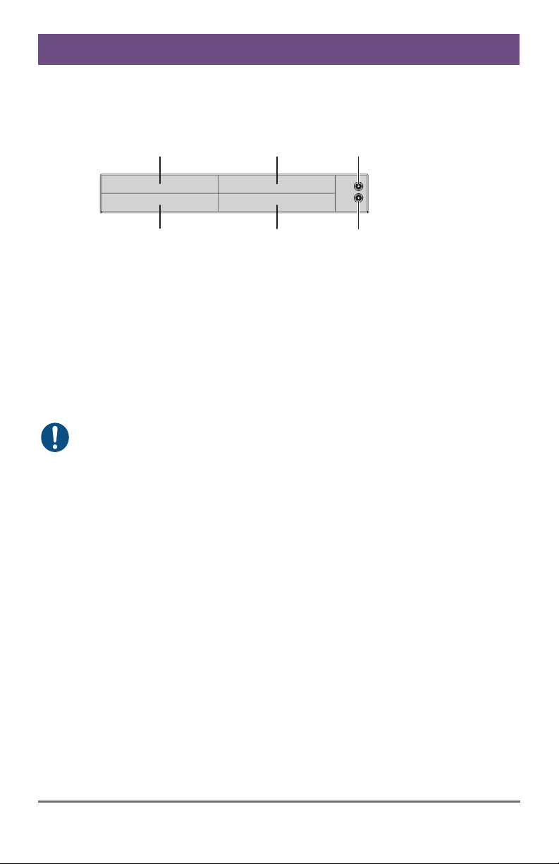
3.6.3 4-fold Vario Chassis 474-BODY4/4R
CPU and CON Unit
Rear View
1 Slot for modules #3
2 Slot for modules #1
3 Connect to 5VDC power supply (standard)
4 Slot for modules #4
5 Slot for modules #2
6 Connect to 5VDC power supply (redundancy, optional)
For operation with three KVM Extender CON modules and a USB 2.0
CON module in a 4-fold vario chassis, two power supplies are necessary.
In this case, redundancy is inapplicable.
Pos: 13 /806-IHSE/Beschreibung/Geräteansichte n/474-xx/6-fac h Vario-Gehäuse 474-BODY6 R @ 6\mod_1304580442488_6. doc @ 50894 @ 3 @ 1
4
1
5
2
6
3
2014-04-15 13
Page 14
Draco (Cross) Repeater
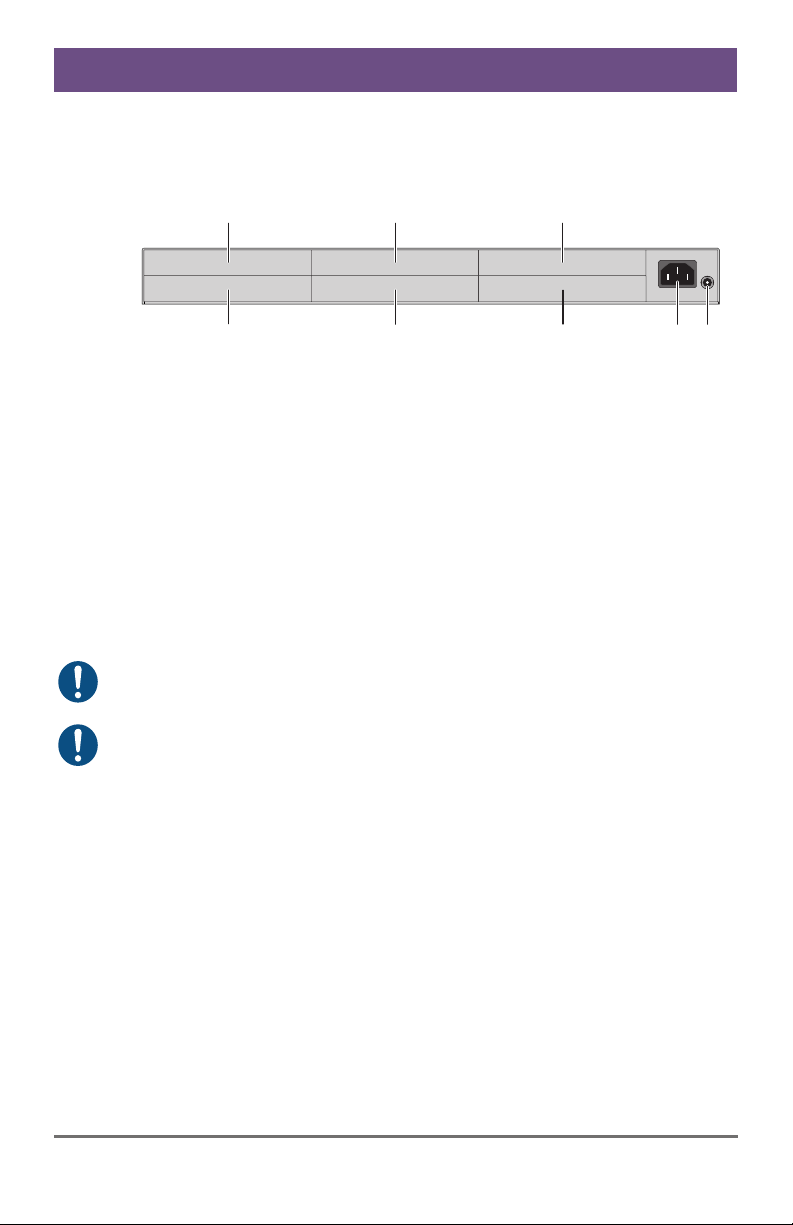
3.6.4 6-fold Vario Chassis 474-BODY6R
CPU and CON Unit
Rear View
1 Slot for modules #5
2 Slot for modules #3
3 Slot for modules #1
4 Connect to power supply (standard)
5 Connect to 5VDC power supply (standard)
6 Slot for modules #6
7 Slot for modules #4
8 Slot for modules #2
For operation with KVM Extender modules in a 6-fold vario chassis, two
power supplies are necessary. In this case, redundancy is inapplicable.
The 6-fold vario chassis is not equipped with a fuse on its primary side.
Therefore the protection against excessive currents has to be provided by
the electrical installation of the building.
Pos: 14 /806-IHSE/Beschreibung/Geräteansichte n/481-xx/6-fac h Vario-Gehäuse 474-BODY6B P @ 9\mod_1367827188730_6. doc @ 71694 @ 3 @ 1
6
1
7
2
8
3
5
4
14 2014-04-15
Page 15
Description
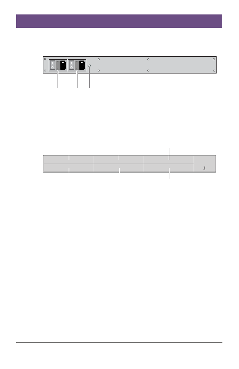
3.6.5 6-fold Vario Chassis 474-BODY6BP
CPU and CON Unit
Front View
1 Connect to power supply 1
2 Connect to power supply 2 (redundancy)
3 Grounding
Rear View
1 Slot for modules #5
2 Slot for modules #3
3 Slot for modules #1
4 Slot for modules #6
5 Slot for modules #4
6 Slot for modules #2
Pos: 15 /806-IHSE/Beschreibung/Geräteansichte n/474-xx/6-fac h Vario-Gehäuse 474-BODY6B PF @ 11\mod_1392644763729 _6.doc @ 132650 @ 3 @ 1
123
45
1
2
6
3
2014-04-15 15
Page 16
Draco (Cross) Repeater
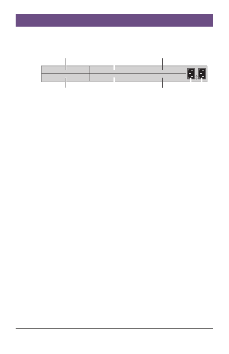
3.6.6 6-fold Vario Chassis 474-BODY6BPF
CPU and CON Unit
67
8
Pos: 16 /806-IHSE/zz_Layout/Seitenumbruch @ 8\ mod_1348581820516_0.doc @ 69462 @ @ 1
1
2
Rear View
1 Slot for modules #5
2 Slot for modules #3
3 Slot for modules #1
4 Connect to power supply 1
5 Connect to power supply 2 (redundancy)
6 Slot for modules #2
7 Slot for modules #4
8 Slot for modules #6
3
4 5
16 2014-04-15
Page 17
Description
Pos: 17 /806-IHSE/Beschreibung/Geräteansichte n/474-xx/21-fac h Vario-Gehäuse 474-BODY 21R @ 8\mod_1348579151346_ 6.doc @ 69400 @ 3 @ 1
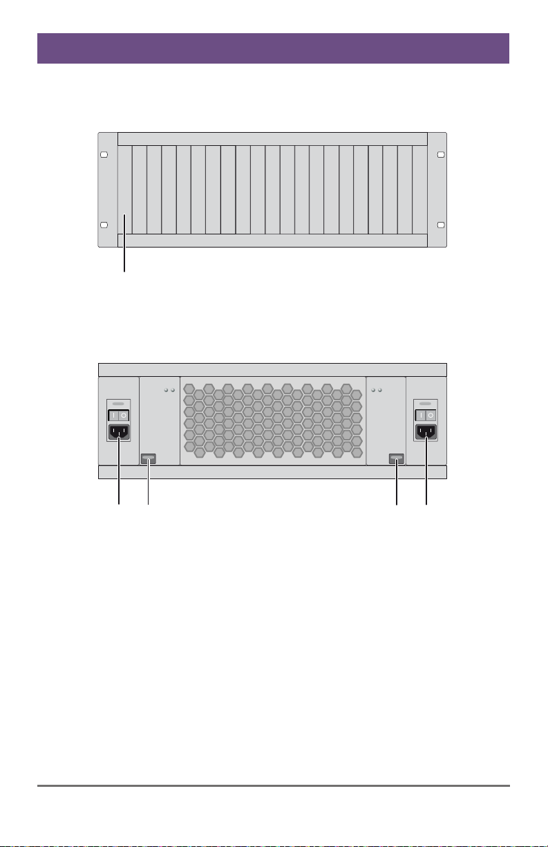
3.6.7 21-fold Vario Chassis 474-BODY21R
CPU and CON Unit
Rear View
1 Slots for modules #1 - #21
Front View
1 Connect to power supply 2
2 Locking for power supply 2 (redundancy)
3 Locking for power supply 1 (standard)
4 Connect to power supply 1
Pos: 18 /806-IHSE/Beschreibung/Geräteansichte n/485-xx/485-BC @ 11\mod_1395150015320_6.d oc @ 140874 @ 3 @ 1
1
2
1
3
4
2014-04-15 17
Page 18
Draco (Cross) Repeater
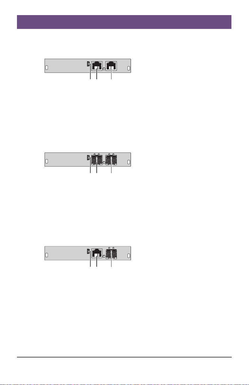
3.6.8 Model 485-BC
Module
12 3
Rear View
1 Service port
2 Connect to interconnect cable 1
3 Connect to interconnect cable 2
Pos: 19 /806-IHSE/Beschreibung/Geräteansichte n/485-xx/485-BS @ 11\mod_1395151298709_6.d oc @ 140905 @ 3 @ 1
3.6.9 Model 485-BS
Module
12 3
Rear View
1 Service port
2 Connect to interconnect cable 1
3 Connect to interconnect cable 2
Pos: 20 /806-IHSE/Beschreibung/Geräteansichte n/485-xx/485-BX @ 11\mod_1395153879791_6.d oc @ 140936 @ 3 @ 1
3.6.10 Model 485-BX
Module
12 3
Rear View
1 Service port
2 Connect to interconnect cable 1
3 Connect to interconnect cable 2
Pos: 21 /806-IHSE/Beschreibung/Geräteansichte n/485-xx/485-BCC @ 11\mod_1395153925309_6. doc @ 140967 @ 3 @ 1
18 2014-04-15
Page 19
Description
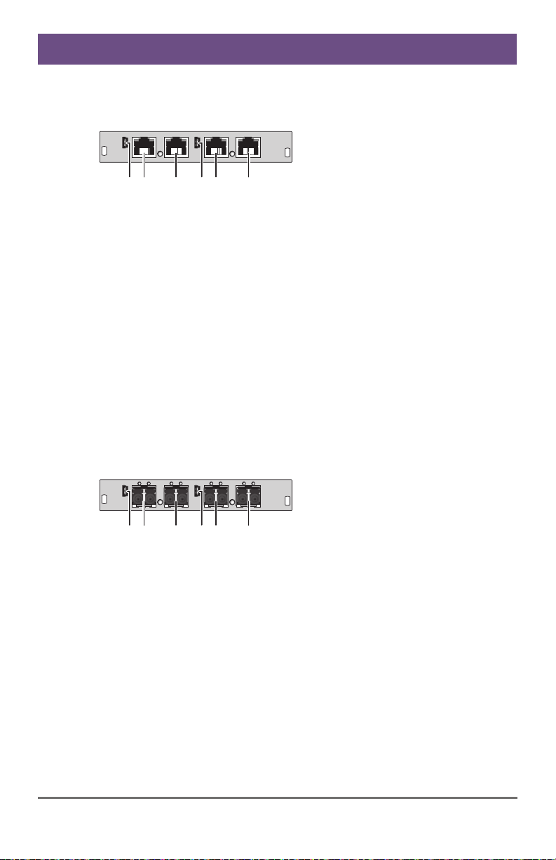
3.6.11 Model 485-BCC
Module
142 3 65
Rear View
1 Service port (repeater #1)
2 Connect to interconnect cable 1
(repeater #1)
3 Connect to interconnect cable 2
(repeater #1)
4 Service port (repeater #2)
5 Connect to interconnect cable 1
(repeater #2)
6 Connect to interconnect cable 2
(repeater #2)
Pos: 22 /806-IHSE/Beschreibung/Geräteansichten/ 485-xx/485-BSS @ 11\mod_139 5154011282_6.doc @ 140998 @ 3 @ 1
3.6.12 Model 485-BSS
Module
2 3 5 6
14
Rear View
1 Service port (repeater #1)
2 Connect to interconnect cable 1
(repeater #1)
3 Connect to interconnect cable 2
(repeater #1)
4 Service port (repeater #2)
5 Connect to interconnect cable 1
(repeater #2)
6 Connect to interconnect cable 2
(repeater #2)
Pos: 23 /806-IHSE/Beschreibung/Geräteansichten/ 485-xx/485-BXX @ 11\mod_139 5154080863_6.doc @ 141029 @ 3 @ 1
2014-04-15 19
Page 20
Draco (Cross) Repeater
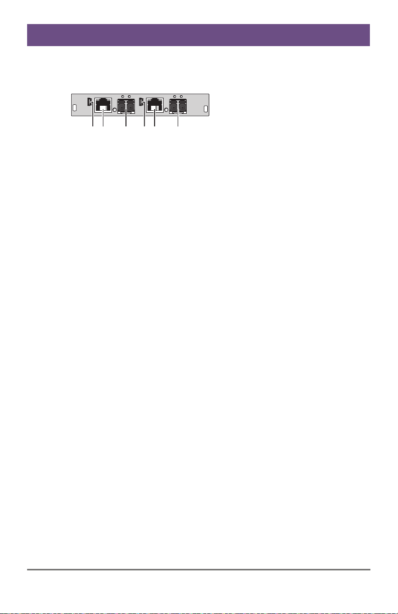
3.6.13 Model 485-BXX
Module
2 3 5 6
14
Rear View
1 Service port (repeater #1)
2 Connect to interconnect cable 1
(repeater #1)
3 Connect to interconnect cable 2
(repeater #1)
4 Service port (repeater #2)
5 Connect to interconnect cable 1
(repeater #2)
6 Connect to interconnect cable 2
(repeater #2)
Pos: 24 /806-IHSE/Beschreibung/Diagnose LEDs/ UEB_Diagnose_LEDs @ 6\mod_1304 584004723_6.doc @ 51146 @ @ 1
20 2014-04-15
Page 21
Description
3.7 Status LEDs
Pos: 25 /806-IHSE/Beschreibung/Diagnose LEDs/485- xx @ 11\mod_1395154726 794_6.doc @ 141055 @ 3 @ 1
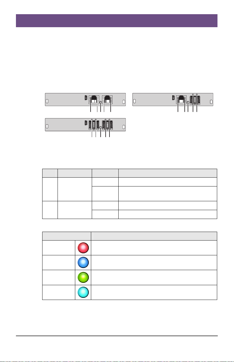
3.7.1 Status (Cross) Repeater Module
The (Cross) Repeater module is fitted with a multi color LED for overall
status indication and with two further LEDs for indication of the connection
status.
Module
Pos: 26 /806-IHSE/Installation/UEB_Installa tion @ 5\mod_1278574971589 _6.doc @ 41768 @ 1 @ 1
12345
12 3 45
Rear View Rear View
LED 1/2 and 4/5: Connection Status
Pos. LED Status Description
Failure LED
(green)
Status LED
(green)
Off Connection available 1/4
On or
Flashing
Connection failure (flashing for about
20 s following a connection failure)
Flashing No connection via interconnect cable 2/5
On Connection available
LED 3: Device Status
LED color Description
Red Device ready
Blue
Green
Link 1 (left connector) available, Link 2 (right
connector) not detected
Link 2 (right connector) available, Link 1 (left
connector) not detected
Light Blue
Link 1 (left connector) and Link 2 (right connector)
available
12345
2014-04-15 21
Page 22
Draco (Cross) Repeater
4 Installation
Pos: 27 /806-IHSE/Installation/Lieferumfang pr üfen/485-xx @ 11\mod_13 95155216299_6.doc @ 141092 @ 2 @ 1
4.1 Package Contents
Your extender package contains the following items:
(Cross) Repeater:
(Cross) Repeater in the vario chassis
1x (redundancy 2x) 5 VDC international power supply unit per KVM
Extender unit (depending on chassis)
1x (redundancy 2x) country-specific power cord (depending on
chassis)
Quick Setup
If anything is missing, contact your dealer.
Pos: 28 /806-IHSE/Installation/System anschließ en/485-xx @ 11\mod_13 95155663403_6.doc @ 141123 @ 23 @ 1
4.2 System anschließen
4.2.1 (Cross) Repeater Setup
Pos: 29 /806-IHSE/Installation/Installatio nsbeispiele/485- xx @ 11\mod_13951562951 71_6.doc @ 141154 @ 2 @ 1
First time users are recommended to setup the system in the same room
as a test setup. This will allow you to identify and solve any cabling
problems, and experiment with your system more conveniently.
Please verify that interconnect cables, interfaces, and handling of the
devices comply with the requirements (see Chapter
1. Switch off all devices.
2. Connect the (Cross) Repeater with the interconnect cable(s).
3. Connect the chassis of the (Cross) Repeater to the power supply.
4. Power up the system.
To power up the system, the following sequence is recommended:
Monitor – CON Unit – (Cross) Repeater – CPU Unit – source.
7, Page 26).
22 2014-04-15
Page 23
Installation
4.3 Example Applications
This section illustrates typical installations of (Cross) Repeaters:
Pos: 58 /806-IHSE/Installation/Installatio nsbeispiele/477- xx_COMP @ 5\mod_12911242643 28_258.doc @ 44766 @ @ 1
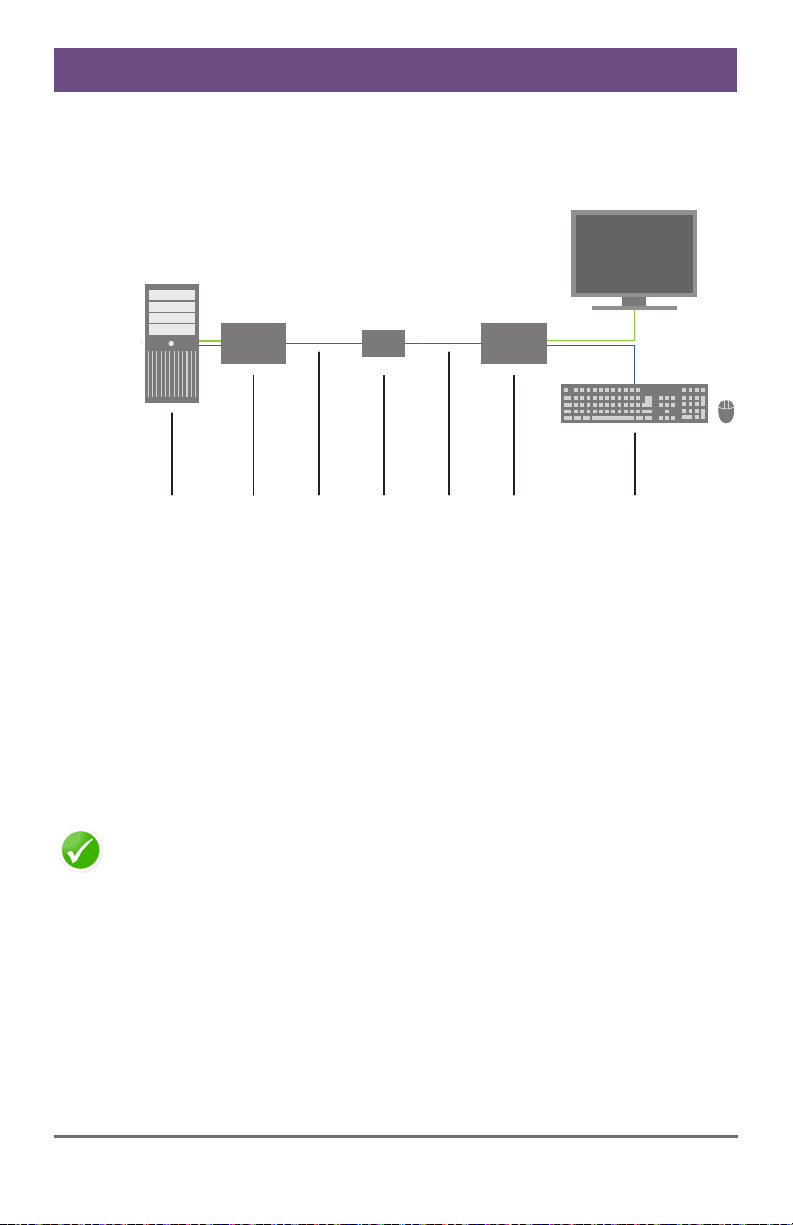
1 2 4 53 761 2 4 53 76
Single Media Conversion
1 Source (computer, CPU)
2 KVM Extender CPU Unit
3 Interconnect cable (Cat X)
4 (Cross) Repeater
5 Interconnect cable (fiber)
6 KVM Extender CON Unit
7 Console (monitor, keyboard, mouse)
The example shown in this application scenario will be primarily
recommended, if connections through KVM matrix must be bypassed in
case of major matrix problems. Therefore KVM extenders with Cat X and
with fiber connector can be directly connected to each other.
2014-04-15 23
Page 24
Draco (Cross) Repeater
Pos: 46 /806-IHSE/zz_Layout/Seitenumbruch @ 8\ mod_1348581820516_0.doc @ 69459 @ @ 1
Pos: 30 /806-IHSE/Konfiguration/UEB_Konfigur ation @ 5\mod_1278575517 073_6.doc @ 41846 @ 1 @ 1
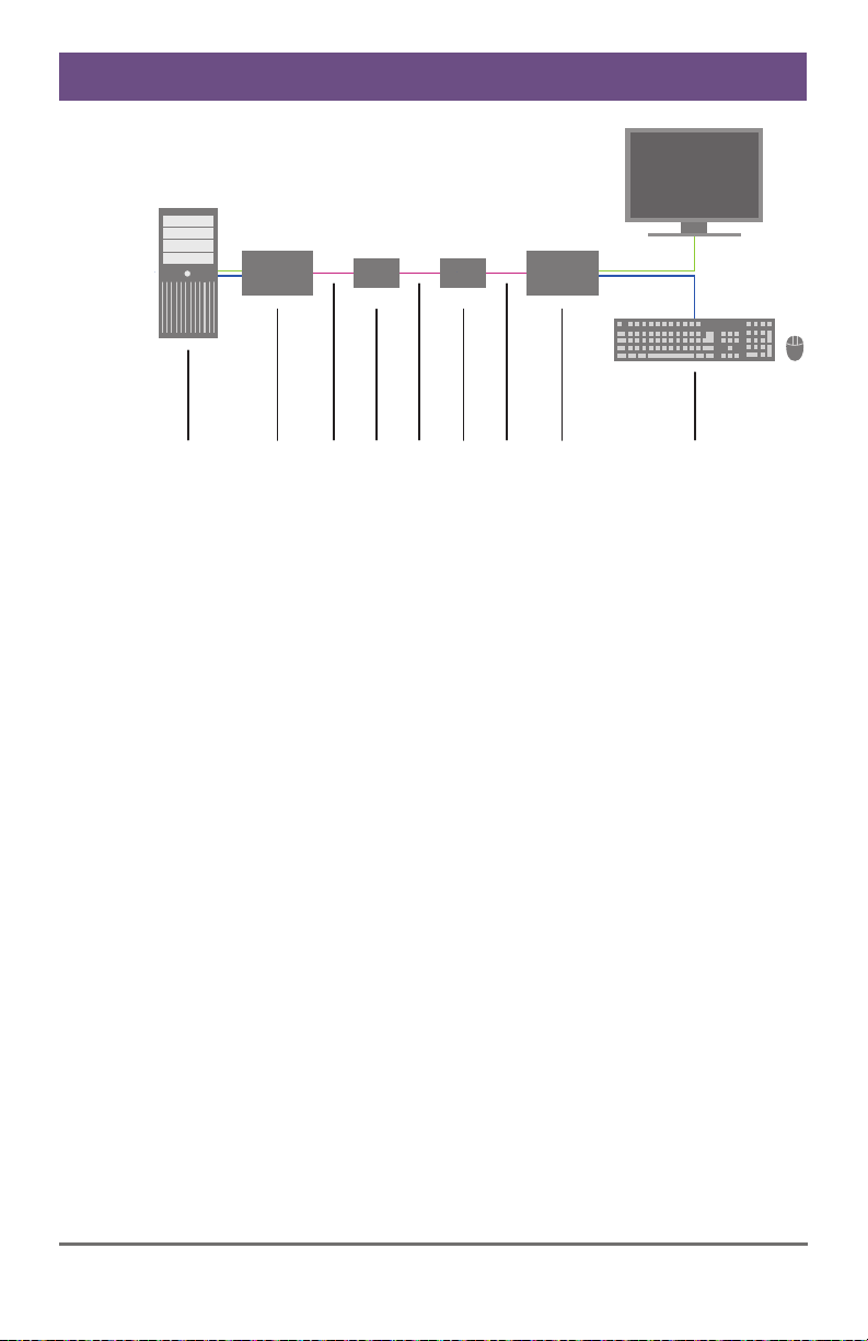
1 2 4 5 83 7 96
Dual Media Conversion
1 Source (computer, CPU)
2 KVM Extender CPU Unit
3 Interconnect cable (Cat X)
4 (Cross) Repeater #1
5 Interconnect cable (fiber)
6 (Cross) Repeater #2
7 Interconnect cable (Cat X)
8 KVM Extender CON Unit
9 Console (monitor, keyboard, mouse)
24 2014-04-15
Page 25

Configuration
5 Configuration
Pos: 31 /806-IHSE/Konfiguration/485_Einleitu ng @ 11\mod_1395156666210 _6.doc @ 141185 @ @ 1
The (Cross) Repeater does not require any configuration and is ready for
use per default.
Pos: 32 /806-IHSE/Betrieb/UEB_Betrieb @ 5\mod_1278 577614980_6.doc @ 41970 @ 1 @ 1
6 Operation
Pos: 33 /806-IHSE/Betrieb/485_Einleitung @ 11\ mod_1395156725331_6.d oc @ 141216 @ @ 1
Pos: 34 /806-IHSE/Technische Daten/UEB_Technisc he Daten @ 5\mod_1278578165261 _6.doc @ 42096 @ 1 @ 1
The (Cross) Repeater does not have any adjustable operating modes and
is ready for use per default.
2014-04-15 25
Page 26
Draco (Cross) Repeater
7 Specifications
Pos: 35 /806-IHSE/Technische Daten/Schnittste llen/UEB_Schnitts tellen @ 5\mod_1278578201 870_6.doc @ 42114 @ 2 @ 1
7.1 Interfaces
Pos: 36 /806-IHSE/Technische Daten/Schnittste llen/RJ45 (Geräteko mmunikation) @ 5\mod_127857 8339308_6.doc @ 42186 @ 3 @ 1
7.1.1 RJ45 (Interconnect)
Communication between Cat X devices requires a 1000BASE-T
connection.
Connector wiring must comply with EIA/TIA-568-B (1000BASE-T), with
RJ45 connectors at both ends. All four cable wire pairs are used.
Pos: 37 /806-IHSE/Technische Daten/Schnittste llen/Glasfaser SFP Typ LC @ 5\mod_1278937700855_6. doc @ 43149 @ 3 @ 1
7.1.2 Fiber SFP Type LC (Interconnect)
Pos: 38 /806-IHSE/Technische Daten/Verbindungs kabel/UEB_Verbindung skabel @ 5\mod_1279191 107845_6.doc @ 43870 @ 2 @ 1
Communication of fiber devices is performed via Gigabit SFPs that are
connected to suitable fibers fitted with connectors type LC (see
Chapter 7.2.2, Page 28).
The correct function of the device can only be guaranteed with SFPs
provided by the manufacturer.
SFP modules can be damaged by electrostatic discharge (ESD).
Please consider ESD handling specifications.
26 2014-04-15
Page 27
Specifications
7.2 Interconnect Cable
Pos: 39 /806-IHSE/Technische Daten/Verbindungs kabel/Verbindungskabe l (Cat X) @ 5\mod_12785784 06026_6.doc @ 42205 @ 3 @ 1
7.2.1 Cat X
A point-to-point connection is required. Operation with several patch fields
is possible. Routing over an active network component, such as an
Ethernet Hub, Router or Matrix, is not allowed.
Avoid routing Cat X cables along power cables.
If the site has 3-phase AC power, try to ensure that CPU Unit and
CON Unit are on the same phase.
To maintain regulatory EMC compliance, correctly installed shielded Cat X
cable must be used throughout the interconnection link.
To maintain regulatory EMC compliance, all Cat X cables need to carry
ferrites on both cable ends close to the device.
Type of Interconnect Cable
The (Cross) Repeater requires interconnect cabling specified for Gigabit
Ethernet (1000BASE-T). The use of solid-core (AWG24), shielded, Cat 5e
(or better) is recommended.
Cat X Solid-Core Cable
AWG24
S/UTP (Cat 5e) cable according to EIA/TIA568-B. Four pairs of wires AWG24.
Connection according to EIA/TIA-568-B
(1000BASE-T).
Cat X Patch Cable
AWG26/8
S/UTP (Cat 5e) cable according to EIA/TIA568-B. Four pairs of wires AWG26/8.
Connection according to EIA/TIA-568-B
(1000BASE-T).
The use of flexible cables (patch cables) type AWG26/8 is possible,
however the maximum possible extension distance is halved.
Pos: 40 /806-IHSE/Technische Daten/Verbindungs kabel/Verbindungskabe l (Cat X)_Kabellänge 47 7-xx @ 5\mod_1278937761 105_6.doc @ 43167 @ @ 1
Maximum Acceptable Cable Length
Cat X Installation Cable
140 m (400 ft)
AWG24
Cat X Patch Cable
70 m (200 ft)
AWG26/8
Pos: 41 /806-IHSE/Technische Daten/Verbindungs kabel/Verbindungskabe l (LWL) @ 5\mod_127893796 7667_6.doc @ 43186 @ 3 @ 1
2014-04-15 27
Page 28
Draco (Cross) Repeater
7.2.2 Fiber
A point-to-point connection is necessary. Operation with multiple patch
panels is allowed. Routing over active network components, such as
Ethernet Hubs, Switches or Routers, is not allowed.
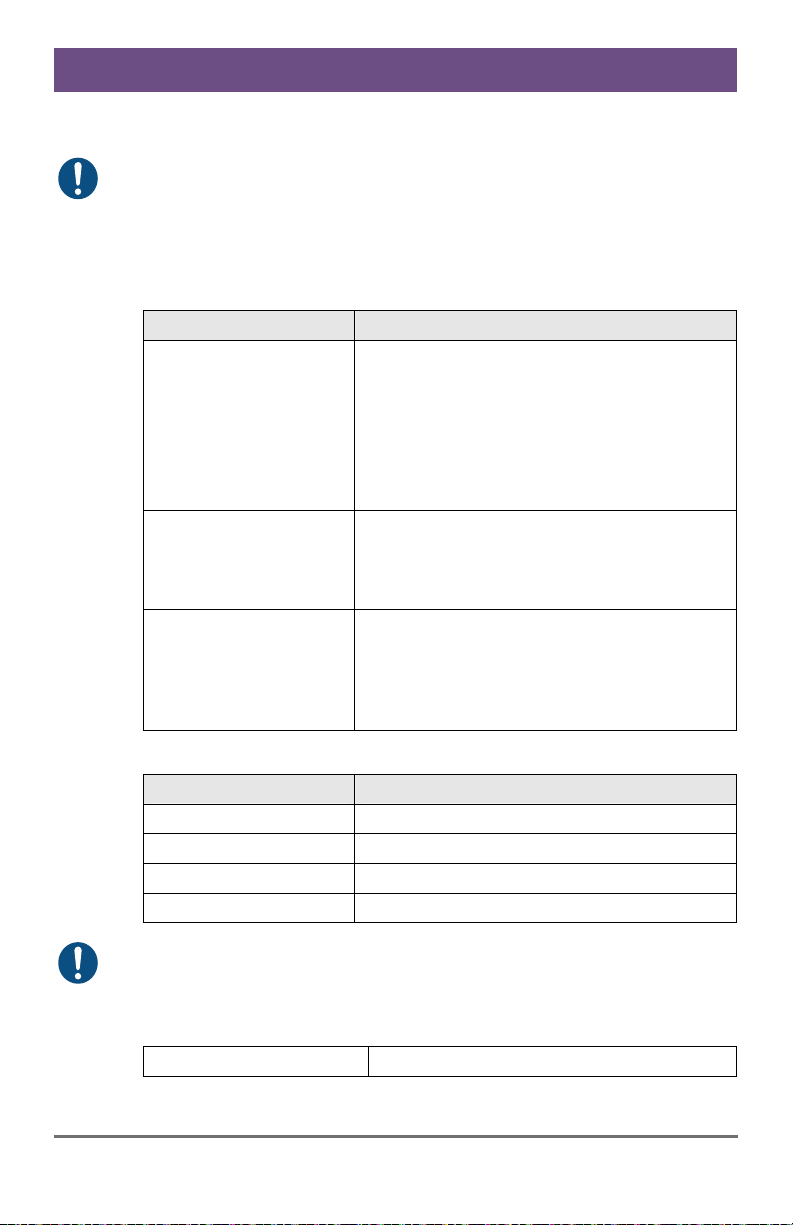
Type of Interconnect Cable
(Cable notations according to VDE)
Type of cable Specifications
Single-mode 9μm Two fibers 9μm
Multi-mode 50μm Two fibers 50μm
Multi-mode 62.5μm Two fibers 62.5μm
I-V(ZN)H 2E9 (in-house patch cable)
I-V(ZN)HH 2E9 (in-house breakout cable)
I/AD(ZN)H 4E9 (in-house or outdoor
breakout cable, resistant)
A/DQ(ZN)B2Y 4G9 (outdoor cable, with
protection against rodents)
I-V(ZN)H 2G50 (in-house patch cable)
I/AD(ZN)H 4G50 (in-house or outdoor
breakout cable, resistant)
I-V(ZN)HH 2G62.5 (in-house breakout
cable)
A/DQ(ZN)B2Y 4G62.5 (outdoor cable,
with protection against rodents)
Maximum Acceptable Cable Length
Type of cable Maximum Acceptable Cable Length
Single-mode 9μm 10,000 m (32,800 ft)
Multi-mode 50μm (OM3) 1,000 m (3,280 ft)
Multi-mode 50μm 400 m (1,300 ft)
Multi-mode 62.5μm 200 m (650 ft)
If you use single-mode SFPs with multi-mode fibers, you normally can
double the maximum acceptable cable length.
Pos: 42 /806-IHSE/Technische Daten/Verbindungs kabel/Verbindungskabe l (LWL)_Steckver binder 477-xx @ 5\mod_12789 54447542_6.doc @ 43740 @ @ 1
Type of Connector
Connector
Pos: 43 /806-IHSE/Technische Daten/Pinbelegungen/ UEB_Pinbelegungen @ 5\ mod_1278578683636_6. doc @ 42315 @ 2 @ 1
LC Connector
28 2014-04-15
Page 29
Specifications
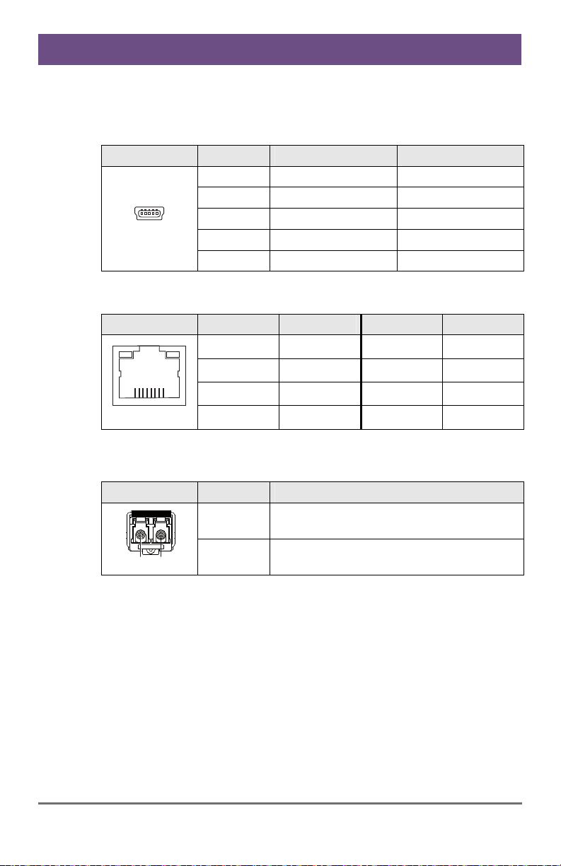
7.3 Connector Pinouts
Pos: 44 /806-IHSE/Technische Daten/Pinbelegungen/ Buchse Mini-USB Typ B @ 5\ mod_1278578794167_6.doc @ 42387 @ @ 1
Connector Mini USB Type B
Picture Pin Signal Color
1 VCC (+5VDC) Red
2 Data – White
3 Data + Green
4 n.c. –
5 GND Black
1 D1+ 5 D3–
2 D1– 6 D2–
3 D2+ 7 D4+
4 D3+ 8 D4–
Pos: 45 /806-IHSE/Technische Daten/Pinbelegungen/ RJ45 @ 5\mod_12785788 20011_6.doc @ 42405 @ @ 1
RJ45
Picture Pin Signal Pin Signal
Pos: 46 /806-IHSE/Technische Daten/Pinbelegungen/ Glasfaser SFP Typ LC @ 5\ mod_1278938501151_6.doc @ 43210 @ @ 1
Fiber SFP Typ LC
1
....5
8..........1
Picture Diode Signal
1 Data OUT
2 Data IN
12
Pos: 47 /806-IHSE/Technische Daten/Stromversorgung/ 485-xx @ 11\mod_13951 57341242_6.doc @ 141242 @ 2 @ 1
2014-04-15 29
Page 30
Draco (Cross) Repeater
7.4 Power Supply
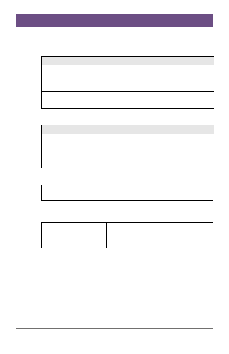
AC Power Supply
Model Max. Current Max. Voltage Frequency
474-BODY2N 700 mA max. 100-240 V 50/60 Hz
474-BODY6R 1,400 mA max. 100-240 V 47-63 Hz
474-BODY6BP 800 mA max. 100-240 V 50/60 Hz
474-BODY6BPF 800 mA max. 100-240 V 50/60 Hz
474-BODY21/4U 4,000 mA max. 2x 100-240 V 50/60 Hz
DC Power Supply
Model Max. Current Max. Voltage
474-BODY2/2R 3,000 mA 5 VDC
474-BODY2N 5,000 mA 5 VDC
474-BODY4/4R 5,000 mA 5 VDC
474-BODY6R 8,000 mA 5 VDC
Power Requirement
Power Requirement
(per Unit)
Pos: 48 /806-IHSE/Technische Daten/Einsatzbeding ungen/ATB_Einsat zbedingungen @ 5\mod_12 78578980026_6.doc @ 42480 @ 2 @ 1
(Cross) Repeater:
Max. 300 mA
7.5 Environmental Conditions
Operating Temperature
Storage Temperature
Relative Humidity
Pos: 49 /806-IHSE/Technische Daten/Abmessungen/47 4-xx @ 6\mod_1304586358 176_6.doc @ 51345 @ 2 @ 1
30 2014-04-15
41 to 113°F (5 to 45°C)
–13 to 140°F (–25 to 60°C)
Max. 80% non-condensing
Page 31
Specifications
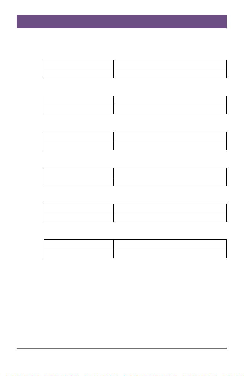
7.6 Size
Devices in the 2-fold Vario Chassis 1
CPU Unit / CON Unit
Shipping Box
145 x 147 x 41 mm (5.7" x 5.8" x 1.7")
210 x 140 x 165 mm (8.3" x 5.5" x 6.5")
Devices in the 2-fold Vario Chassis 2
CPU Unit / CON Unit
Shipping Box
221 x 147 x 41 mm (8.7" x 5.8" x 1.7")
550 x 365 x 115 mm (21.7" x 14.4" x 4.5")
Devices in the 4-fold Vario Chassis
CPU Unit / CON Unit
Shipping Box
293 x 147 x 41 mm (11.5" x 5.8" x 1.7")
550 x 365 x 115 mm (21.7" x 14.4" x 4.5")
Devices in the 6-fold Vario Chassis 6R
CPU Unit / CON Unit
Shipping Box
442 x 147 x 41 mm (17.4" x 5.8" x 1.7")
760 x 365 x 115 mm (29.9" x 14.4" x 4.5")
Devices in the 6-fold Vario Chassis 6BP / 6BPF
CPU Unit / CON Unit
Shipping Box
442 x 250 x 41 mm (17.4" x 9.8" x 1.7")
550 x 372 x 155 mm (21.7" x 14.6" x 6.1")
Devices in the 21-fold Vario Chassis
Pos: 50 /806-IHSE/zz_Layout/Seitenumbruch @ 8\ mod_1348581820516_0.doc @ 69462 @ @ 1
CPU Unit / CON Unit
Shipping Box
482 x 462 x 176 mm (19.0" x 18.2" x 6.9")
645 x 574 x 368 mm (25.4" x 22.6" x 14.5")
2014-04-15 31
Page 32
Draco (Cross) Repeater
Pos: 51 /806-IHSE/Technische Daten/Transportgewic ht /474-xx @ 6\mod_130 4586413879_6.doc @ 51363 @ 2 @ 1
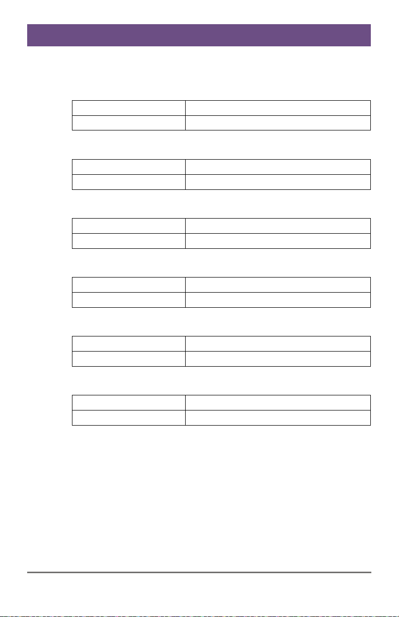
7.7 Shipping Weight
Devices in the 2-fold Vario Chassis 1
CPU Unit / CON Unit
Shipping Box
0.4 kg (0.9 lb)
2.2 kg (4.9 lb)
Devices in the 2-fold Vario Chassis 2
CPU Unit / CON Unit
Shipping Box
0.8 kg (1.8 lb)
2.6 kg (5.7 lb)
Devices in the 4-fold Vario Chassis
CPU Unit / CON Unit
Shipping Box
0.9 kg (2.0 lb)
3.4 kg (7.5 lb)
Devices in the 6-fold Vario Chassis 6R
CPU Unit / CON Unit
Shipping Box
1.4 kg (3.1 lb)
4.6 kg (10.1 lb)
Devices in the 6-fold Vario Chassis 6BP / 6BPF
CPU Unit / CON Unit
Shipping Box
2.5 kg (5.5 lb)
3.5 kg (7.7 lb)
Devices in the 21-fold Vario Chassis
Pos: 52 /806-IHSE/Hilfe im Problemfall/UEB_Hilfe i m Problemfall @ 5\mod_127857 9113839_6.doc @ 42536 @ 1 @ 1
CPU Unit / CON Unit
Shipping Box
10.0 kg (22.1 lb)
14.5 kg (32.0 lb)
32 2014-04-15
Page 33
Troubleshooting
8 Troubleshooting
Pos: 53 /806-IHSE/Hilfe im Problemfall/Allgemeine S törung/485-xx @ 11\mod_1 395218793981_6.doc @ 141316 @ 2 @ 1
8.1 General Failures
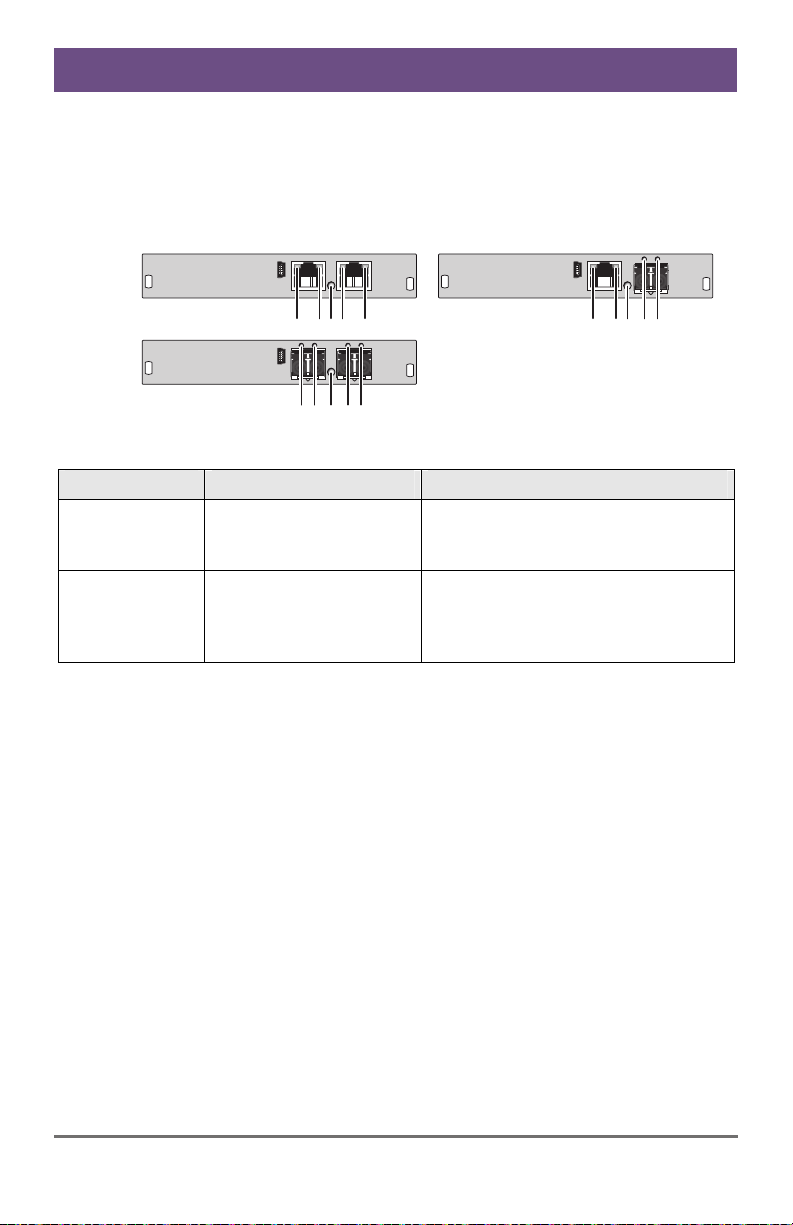
Module
12345
12 3 45
Rear View
Diagnosis Possible Reason Measure
LED 3 off
Power supply
Check power supply units and
the connection to the power
network.
LED 2 off or
LED 5 off
Connection between
(Cross) Repeater and
Check interconnect cables and
connections.
KVM extender unit or
KVM matrix
Pos: 54 /806-IHSE/Technische Unterstützung/ATB_ Technische Unterstütz ung @ 5\mod_1278579487089 _6.doc @ 42650 @ 122 @ 1
12345
2014-04-15 33
Page 34

Draco (Cross) Repeater
9 Technical Support
Prior to contacting support please ensure you have read this manual, and
then installed and set-up your (Cross) Repeater as recommended.
9.1 Support Checklist
To efficiently handle your request it is necessary that you complete a
support request checklist (Download). Please ensure that you have the
following information available before you call:
Company, name, phone number and email
Type and serial number of the device (see bottom of device)
Date and number of sales receipt, name of dealer if necessary
Issue date of the existing manual
Nature, circumstances and duration of the problem
Components included in the system (such as graphic source/CPU,
OS, graphic card, monitor, USB-HID/USB 2.0 devices, interconnect
cable) including manufacturer and model number
Results from any testing you have done
9.2 Shipping Checklist
1. To return your device, contact your dealer to obtain a RMA number
(Return-Material-Authorization).
2. Package your devices carefully, preferably using the original box.
Add all pieces which you received originally.
3. Note your RMA number visibly on your shipment.
Devices that are sent in without a RMA number cannot be accepted. The
shipment will be sent back without being opened, postage unpaid.
Pos: 55 /806-IHSE/Zertifikate/UEB_Zertifi kate @ 5\mod_1278579534933 _6.doc @ 42668 @ 1 @ 1
34 2014-04-15
 Loading...