

Page 1
User Manual
Edition: 2013-12-06
Draco
KVM Extender
Model:
K482 Series
IHSE GmbH
Maybachstrasse 11
88094 Oberteuringen
Germany
info@ihse.de
www.ihse.de
Tel. +49 7546-9248-0
Fax +49 7546-9248-48
Page 2

Draco KVM Extender
Copyright
© 2013. All rights reserved. This information may not be reproduced in any
manner without the prior written consent of the manufacturer.
Information in this document is subject to change without notice.
Trademarks
All trademark and trade names mentioned in this document are
acknowledged to be the property of their respective owners.
Disclaimer
While every precaution has been taken during preparation of this manual,
the manufacturer assumes no liability for errors or omissions. Neither does
the manufacturer assume any liability for damages resulting from the use
of the information contained herein.
The manufacturer reserves the right to change specifications, functions, or
circuitry of the product without notice.
The manufacturer cannot accept liability for damage due to misuse of the
product or due to any other circumstances outside the manufacturer’s
control (whether environmental or installation related). The manufacturer
shall not be liable for any loss, damage, or injury arising directly, indirectly,
incidentally, or consequently from the use of this product.
2 2013-12-06
Page 3

Contents
Contents
1 About This Manual ....................................................................... 7
1.1 Scope.................................................................................. 7
1.2 Validity ................................................................................ 7
1.3 Cautions and Notes ............................................................ 7
2 Safety Instructions....................................................................... 8
3 Description ................................................................................... 9
3.1 Application .......................................................................... 9
3.2 System Overview .............................................................. 10
3.3 Product Range .................................................................. 11
3.3.1 Part Numbers ...................................................... 11
3.3.2 Chassis ............................................................... 11
3.3.3 KVM-Extender Modules ...................................... 12
3.3.4 Upgrade Modules................................................ 12
3.3.5 Devices for free configuration ............................. 13
3.4 Accessories Upgrade Kits ................................................. 14
3.5 Accessories....................................................................... 15
3.6 Device Views .................................................................... 15
3.6.1 2-fold Vario Chassis 474-BODY2/2R .................. 15
3.6.2 2-fold Vario Chassis 474-BODY2N ..................... 16
3.6.3 4-fold Vario Chassis 474-BODY4/4R .................. 16
3.6.4 6-fold Vario Chassis 474-BODY6R ..................... 17
3.6.5 6-fold Vario Chassis 474-BODY6BP................... 18
3.6.6 21-fold Vario Chassis 474-BODY21R ................. 19
3.6.7 Model L- / R474-BDHC / -B2HC ......................... 20
3.6.8 Model L- / R474-BDHS/X / -B2HS/X ................... 20
3.6.9 Model L- / R474-BDHCR / -B2HCR .................... 21
3.6.10 Model L- / R474-BDHS/XR / -B2HS/XR.............. 21
3.6.11 Model L- / R474-BXH.......................................... 21
3.6.12 Model L- / R474-BXE .......................................... 22
3.6.13 Model L- / R474-BUE.......................................... 22
2013-12-06 3
Page 4

Draco KVM Extender
3.6.14 Model L- / R474-BAX .......................................... 22
3.6.15 Model L- / R474-BAP .......................................... 23
3.6.16 Model L- / R474-BXP .......................................... 23
3.6.17 Model L- / R474-BDX.......................................... 24
3.6.18 Model L- / R474-BAH.......................................... 25
3.6.19 Model L- / R474-BDH.......................................... 25
3.6.20 Model L- / R474-BAE .......................................... 26
3.6.21 Model L- / R474-BDE.......................................... 26
3.6.22 Model L- / R474-BDD.......................................... 27
3.6.23 Modell L- / R474-BDA ......................................... 27
3.6.24 Modell L- / R474-BXTC....................................... 28
3.6.25 Modell L- / R474-BXTS ....................................... 28
3.7 Status LEDs ...................................................................... 29
3.7.1 Status KVM-Extender Module............................. 29
3.7.2 Status Upgrade Module Digital Audio ................. 30
3.7.3 Status Upgrade Module USB-HID....................... 31
3.7.4 Status Upgrade module USB 2.0 embedded ...... 32
3.7.5 Status Upgrade Module USB 2.0 ........................ 33
4 Installation .................................................................................. 34
4.1 Package Contents............................................................. 34
4.2 System Setup.................................................................... 36
4.2.1 KVM-Extender Setup .......................................... 36
4.2.2 Setup of Upgrade Modules ................................. 37
4.3 Example Applications........................................................ 38
4.4 Overview Upgrade Modules.............................................. 40
5 Configuration.............................................................................. 41
5.1 Transmission Parameters ................................................. 41
5.2 DDC Settings .................................................................... 41
5.3 Command Mode ............................................................... 42
5.4 USB-HID Ghosting............................................................ 43
5.5 Configuration File.............................................................. 44
5.5.1 Parameters for CPU Units................................... 45
4 2013-12-06
Page 5

Contents
5.5.2 Parameters for CON Units .................................. 46
5.5.3 Parameters for CPU und CON Units................... 47
6 Operation .................................................................................... 48
6.1 Download of DDC Information .......................................... 48
6.2 Parallel Operation of redundant CPU Units....................... 49
7 Specifications............................................................................. 51
7.1 Interfaces .......................................................................... 51
7.1.1 DVI-D Dual Link .................................................. 51
7.1.2 DVI-I Single Link ................................................. 51
7.1.3 USB-HID ............................................................. 51
7.1.4 PS/2 .................................................................... 52
7.1.5 USB 2.0 (transparent) ......................................... 52
7.1.6 RJ45 (Interconnect) ............................................ 52
7.1.7 Fiber SFP Type LC (Interconnect) ...................... 53
7.1.8 Serial Interface.................................................... 53
7.1.9 Serial Interface RS422 ........................................ 54
7.1.10 Analog Audio Interface........................................ 55
7.1.11 Digital Audio Interface......................................... 56
7.2 Interconnect Cable............................................................ 58
7.2.1 Cat X ................................................................... 58
7.2.2 Fiber.................................................................... 59
7.3 Supported Peripherals ...................................................... 60
7.3.1 USB-HID Devices ............................................... 60
7.3.2 USB 2.0 Devices ................................................. 60
7.4 Connector Pinouts ............................................................ 61
7.5 Power Supply.................................................................... 65
7.6 Environmental Conditions ................................................. 66
7.7 Size................................................................................... 66
7.8 Shipping Weight................................................................ 68
8 Troubleshooting......................................................................... 69
8.1 General Failures ............................................................... 69
8.2 Blank Screen..................................................................... 70
2013-12-06 5
Page 6

Draco KVM Extender
8.3 USB-HID ........................................................................... 71
8.4 Serial Connection.............................................................. 72
8.5 Analog Audio..................................................................... 72
8.6 Digital Audio...................................................................... 73
8.7 Upgrade Module USB-HID................................................ 74
8.8 USB 2.0 embedded........................................................... 75
8.9 USB 2.0............................................................................. 76
9 Technical Support ...................................................................... 77
9.1 Support Checklist.............................................................. 77
9.2 Shipping Checklist ............................................................ 77
10 Certificates.................................................................................. 78
10.1 CE Declaration Of Conformity........................................... 78
10.2 North American Regulatory Compliance ........................... 79
10.3 Product Safety ..................................................................79
10.4 WEEE ............................................................................... 80
10.5 RoHS/RoHS 2................................................................... 80
11 Glossary...................................................................................... 81
Pos: 1 /806-IHSE/Zu diesem Handbuch/ATB_Zu diesem Handbuc h @ 5\mod_1278573163276_6. doc @ 41510 @ 1222 @ 1
6 2013-12-06
Page 7
About This Manual
1 About This Manual
1.1 Scope
This manual describes how to install your KVM Extender, how to operate it
and how to perform trouble shooting.
1.2 Validity
This manual is valid for all devices listed on the front page. The product
code is printed on the base of the devices.
1.3 Cautions and Notes
The following symbols are used in this manual:
This symbol indicates an important operating instruction that should be
followed to avoid any potential damage to hardware or property, loss of
data, or personal injury.
This symbol indicates important information to help you make the best use
of this product.
This symbol indicates best practice information to show recommended
and optimal ways to use this product in an efficient way.
Pos: 2 /806-IHSE/Sicherheitshinweise/ATB_Sic herheitshinweise @ 5\m od_1278573321245_6. doc @ 41528 @ 1 @ 1
2013-12-06 7
Page 8

Draco KVM Extender
2 Safety Instructions
To ensure reliable and safe long-term operation of your KVM Extender
please note the following guidelines:
Installation
Only use in dry, indoor environments.
The KVM Extender and the power supply units can get warm. Do not
situate them in an enclosed space without any airflow.
Do not place the power supply directly on top of the device.
Do not obscure ventilation holes.
Only use power supplies originally supplied with the product or
manufacturer-approved replacements. Do not use a power supply if it
appears to be defective or has a damaged chassis.
Connect all power supplies to grounded outlets. In each case, ensure
that the ground connection is maintained from the outlet socket
through to the power supply's AC power input.
Do not connect the link interface to any other equipment, particularly
network or telecommunications equipment.
Take any required ESD precautions.
In order to disconnect the device completely from the electric circuit, all
power cables have to be removed.
Repair
Do not attempt to open or repair a power supply unit.
Do not attempt to open or repair the KVM Extender. There are no
user serviceable parts inside.
Please contact your dealer or manufacturer if there is a fault.
Pos: 3 /806-IHSE/Beschreibung/UEB_Beschreibung @ 5\ mod_1278573379151_6. doc @ 41546 @ 1 @ 1
8 2013-12-06
Page 9

Description
3 Description
Pos: 4 /806-IHSE/Beschreibung/Verwendungszweck/ 474-xx @ 6\mod_1304579 672848_6.doc @ 50785 @ @ 1
3.1 Application
The KVM Extender is used to increase the distance between a source
(computer, CPU) and its console (keyboard, mouse, and other peripheral
devices).
The KVM Extender is designed for use with Cat X (Twisted Pair)
interconnect cables or fiber interconnect cables.
The KVM Extender with Cat X interconnect cables is unsuitable for
connection between buildings where a fiber optic based product should be
used instead.
The KVM Extender with fiber interconnect cables can also be used with
applications in environments which are difficult in electromagnetical
aspects. Electromagnetical interference can limit the maximum distance
und reliability.
Pos: 5 /806-IHSE/Beschreibung/System-Übersic ht /474-xx @ 6\mod_1304579 735410_6.doc @ 50803 @ @ 1
2013-12-06 9
Page 10
Draco KVM Extender
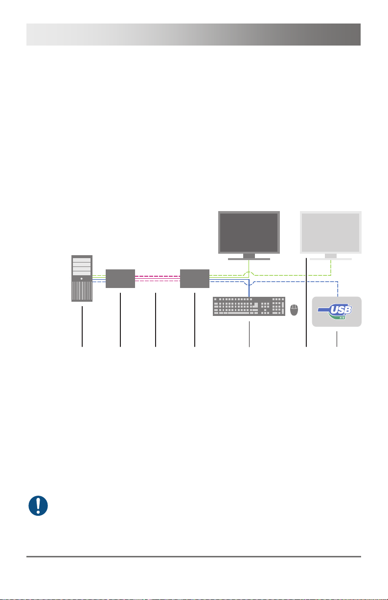
3.2 System Overview
The KVM Extender consists of at least one CPU module and one
CON module. The various modules are summarized respectively in a
vario chassis (2-fold, 4-fold or 6-fold) at CPU site and CON site (CPU and
CON unit).
The CPU module is connected directly to the source (computer, CPU)
using the supplied cables.
The CON module is connected to the console (monitor, keyboard and
mouse).
The CPU Unit and the CON modules communicate with each other
through the interconnect cables.
1
2
3
4
5
6
7
System Overview
1 Source (computer, CPU)
2 KVM Extender CPU Unit
3 Interconnect cable
4 KVM Extender CON Unit
5 Console (monitor, keyboard, mouse)
6 Second monitor (option, only with Dual-Head devices)
7 USB-HID devices (option, only with 4x USB-HID devices)
See Chapter
Pos: 6 /806-IHSE/Beschreibung/Gerätetypen/482- xx @ 10\mod_13856436191 72_6.doc @ 103013 @ 233333 @ 1
4.3, Page 38 for installation examples.
10 2013-12-06
Page 11
Description
3.3 Product Range
3.3.1 Part Numbers
Part numbers for Connections via Cat X or Fiber Cable
All mentioned devices are available in the following versions:
Connection via Cat X cable (x = "C")
Connection via Single-mode fiber cable (x = "S")
High speed connection (3.125 Gbit/s) via Single-mode fiber cable
(x = "X")
Fiber devices can be used with Multi-mode and Single-mode cables (see
Chapter 7.2.2, Page 59).
Part numbers for CPU Unit and CON Unit
The part numbers for the CPU Unit and the CON Unit can be derived from
the part number of the complete device.
CPU Unit: L482
CON Unit: R482
All devices of the K482 series are technically compatible to the devices of
the K474/K477/K481 series.
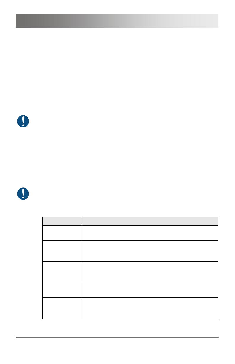
3.3.2 Chassis
Model Description
474-BODY2
474-BODY2R
474-BODY2N
474-BODY4
474-BODY4R
Empty chassis for up to 2 boards, 1x external power
supply unit
Empty chassis for up to 2 boards, 1x external power
supply unit, preparation for redundancy for a second
power supply unit (external)
Empty chassis for up to 2 boards, 1x internal power
supply unit, preparation for redundancy for a second
power supply unit (external)
Empty chassis for up to 4 boards, 1x external power
supply unit
Empty chassis for up to 4 boards, 1x external power
supply unit, preparation for redundancy for a second
power supply unit (external)
2013-12-06 11
Page 12
Draco KVM Extender
Model Description
474-BODY6R
474BODY6BP
474BODY21/4U
Empty chassis for up to 6 boards, 1x internal power
supply unit, preparation for redundancy for a second
power supply unit (external)
Empty chassis for up to 6 boards, active backplane, 2x
internal power supply unit (redundancy)
Empty chassis for up to 21 boards, 1x internal power
supply unit, preparation for redundancy for a second
power supply unit (internal)
3.3.3 KVM Extender Modules
Model Description
L482-BDHx
R482-BDHx
L482-BDHxR
R482-BDHxR
L482-B2Hx
R482-B2Hx
L482-B2HxR
R482-B2HxR
Single-Head module for 1x DVI-D Dual Link
(up to 2560x1600), 2x USB-HID
Single-Head module for 1x DVI-D Dual Link
(up to 2560x1600), 2x USB-HID and redundant
connector for interconnect cables
Dual-Head module for 2x DVI-D Single Link
(up to 1920x1200), 2x USB-HID
Dual-Head module for 2x DVI-D Single Link
(up to 1920x1200), 2x USB-HID and redundant
connector for interconnect cables
3.3.4 Upgrade Modules
Model Description
L474-BXH
R474-BXH
L474-BXE
R474-BXE
L474-BAX
R474-BAX
L474-BAP
R474-BAP
L474-BSX
R474-BSX
Upgrade module with 2x USB-HID
Upgrade module with 2x USB 2.0
Upgrade module with Analog Audio / Serial
(bidirectional)
Upgrade module with Analog Audio / Serial
(bidirectional) and PS/2
Upgrade module with serial connector (RS422)
12 2013-12-06
Page 13
Description
Model Description
L474-BXP
R474-BXP
L474-BDX
R474-BDX
L474-BAH
R474-BAH
L474-BUE
R474-BUE
L474-BAE
R474-BAE
L474-BDH
R474-BDH
L474-BDE
R474-BDE
L474-BDD
R474-BDD
L474-BDA
R474-BDA
L474-BXTx
R474-BXTx
Upgrade module with PS/2 (only available with upgrade
module Analog Audio / Serial)
Upgrade module with Digital Audio (unidirectional)
Upgrade module with Analog Audio / Serial
(bidirectional) and 2x USB-HID
Upgrade module with Analog Audio (bidirectional) and
2x USB 2.0
Upgrade module with Analog Audio / Serial
(bidirectional) and 2x USB 2.0
Upgrade module with Digital Audio (unidirectional) and
2x USB-HID
Upgrade module with Digital Audio (unidirectional) and
2x USB 2.0
Upgrade module with Digital Audio (bidirectional)
Upgrade module with Digital Audio (unidirectional) and
Analog Audio / Serial (bidirectional)
USB 2.0 upgrade module with 4x USB 2.0
3.3.5 Devices for free configuration
Model Description
DRACO
VARIO 2
DRACO
VARIO 2R
DRACO
VARIO 2N
DRACO
VARIO 4
Draco extender for free configuration in a 2-slot vario
chassis, external power supply unit
Draco extender for free configuration in a 2-slot vario
chassis, external power supply unit, preparation for
redundancy for a second external power supply unit
Draco extender for free configuration in a 2-slot vario
chassis, internal power supply unit, preparation for
redundancy of an external power supply unit
Draco extender for free configuration in a 4-slot vario
chassis, external power supply unit
2013-12-06 13
Page 14
Draco KVM Extender
Model Description
DRACO
VARIO 4R
Draco extender for free configuration in a 4-slot vario
chassis, external power supply unit, preparation for
redundancy of a second external power supply unit
DRACO
VARIO 6R
Draco extender for free configuration in a 6-slot vario
chassis, internal power supply unit, preparation for
redundancy of an external power supply unit
DRACO
VARIO 6BP
Draco extender for free configuration in a 6-slot vario
chassis, active backplane, 2x internal power supply unit
(redundancy)
DRACO
VARIO 21/4U
Draco extender for free configuration in a 21-slot 4U
vario chassis, internal power supply unit, preparation for
redundancy for a second external power supply unit
When using redundant power supply units, there will be a load sharing.
Pos: 7 /806-IHSE/Beschreibung/Einbauoptionen/ 474-xx @ 6\mod_13045800 08551_6.doc @ 50839 @ 2 @ 1
3.4 Accessories Upgrade Kits
Model Description
474-2RMK 19"/1U rack mount kit for 2-fold chassis
Pos: 8 /806-IHSE/Beschreibung/Zubehör/482-xx @ 10\ mod_1385644172927_ 6.doc @ 103037 @ 2 @ 1
4742NRMK
474-4RMK 19"/1U rack mount kit for 4-fold chassis
474-6RMK 19"/1U rack mount kit for 6-fold chassis
474-
VPLATE
474-
OPTRED
474-PSU2 Power supply for 2-fold chassis (spare or redundancy)
474-PSU4 Power supply for 4-fold chassis (spare or redundancy)
474-PSU6 Power supply for 6-fold chassis (spare or redundancy)
474-PSU21 Power supply for 6-fold-chassis (spare or redundancy)
474-BLND1 Blind plate 3U/4HP for 2-, 4- and 6-fold chassis
474-BLND2 Blind plate 3U/8HP for 2-, 4- and 6-fold chassis
The KVM Extenders and the provided power supply units can get warm,
for this reason an installation in closed rooms without air circulation is not
allowed. Please note that you will need at least 0.5 U (height unit) for the
ventilation above the extenders, if you mount them into racks.
19"/1U rack mount kit for 2-fold chassis with internal PSU
Fastening strips for screw or snap on for 2-, 4- and 6-fold
chassis
Retrofitting for redundant power supply option (without
power supply) for 2- and 4-fold chassis
14 2013-12-06
Page 15
Description
3.5 Accessories
Model Description
026-2A Serial cable 1.8 m (RS232)
247-U1 USB cable 1.8 m (Type A to B)
260-5G International power supply unit 100...240VAC / 5VDC / 3 A
260-5U International power supply unit 100...240VAC / 5VDC / 4 A
436-ID DVI-D cable 1.8 m (DVI-D)
436-DL59 Dual-Link cable (DMS-59 to DVI-D)
436-DH59 Dual-Head cable (DMS-59 to 2x DVI-D)
445-2H DVI-D splitter cable
455-CK Stereo jack cable 1.6 m (3.5 mm Stereo)
455-CR RCA cable 2.5 m (Cinch male connector)
455-CT TOSLINK cable 1.8 m (F05 male connector)
455-CX Mini-XLR cable 1.8 m (3 pole)
Pos: 9 /806-IHSE/Beschreibung/Geräteansichten/ UEB_Geräteansic hten @ 5\mod_12785737378 08_6.doc @ 41654 @ 2 @ 1
3.6 Device Views
Pos: 10 /806-IHSE/Beschreibung/Geräteansichte n/474-xx/2-fac h Vario-Gehäuse 474-BODY2/ 2R @ 6\mod_130458028056 6_6.doc @ 50858 @ 3 @ 1
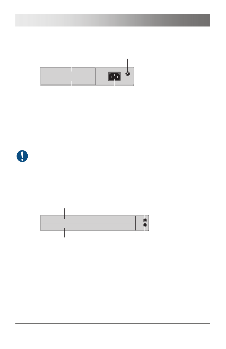
3.6.1 2-fold Vario Chassis 474-BODY2/2R
CPU and CON Unit
3
1
4
2
Rear View
1 Slot for modules #1
2 Connect to 5VDC power supply (standard)
3 Slot for modules #2
4 Connect to 5VDC power supply (redundancy, optional)
Pos: 11 /806-IHSE/Beschreibung/Geräteansichte n/474-xx/2-fac h Vario-Gehäuse 474-BODY2 N @ 8\mod_1348578478411_6. doc @ 69380 @ 3 @ 1
2013-12-06 15
Page 16
Draco KVM Extender
3.6.2 2-fold Vario Chassis 474-BODY2N
CPU and CON Unit
3
4
1
2
Rear View
1 Slot for modules #1
2 Connect to power supply (standard)
3 Slot for modules #2
4 Connect to 5VDC power supply (redundancy)
The 2-fold vario chassis with an internal power supply is not equipped with
a fuse on primary side. Therefore the protection against excessive
currents has to be provided by the electrical installation of the building.
Pos: 12 /806-IHSE/Beschreibung/Geräteansichte n/474-xx/4-fac h Vario-Gehäuse 474-BODY4/ 4R @ 6\mod_130458035909 8_6.doc @ 50876 @ 3 @ 1
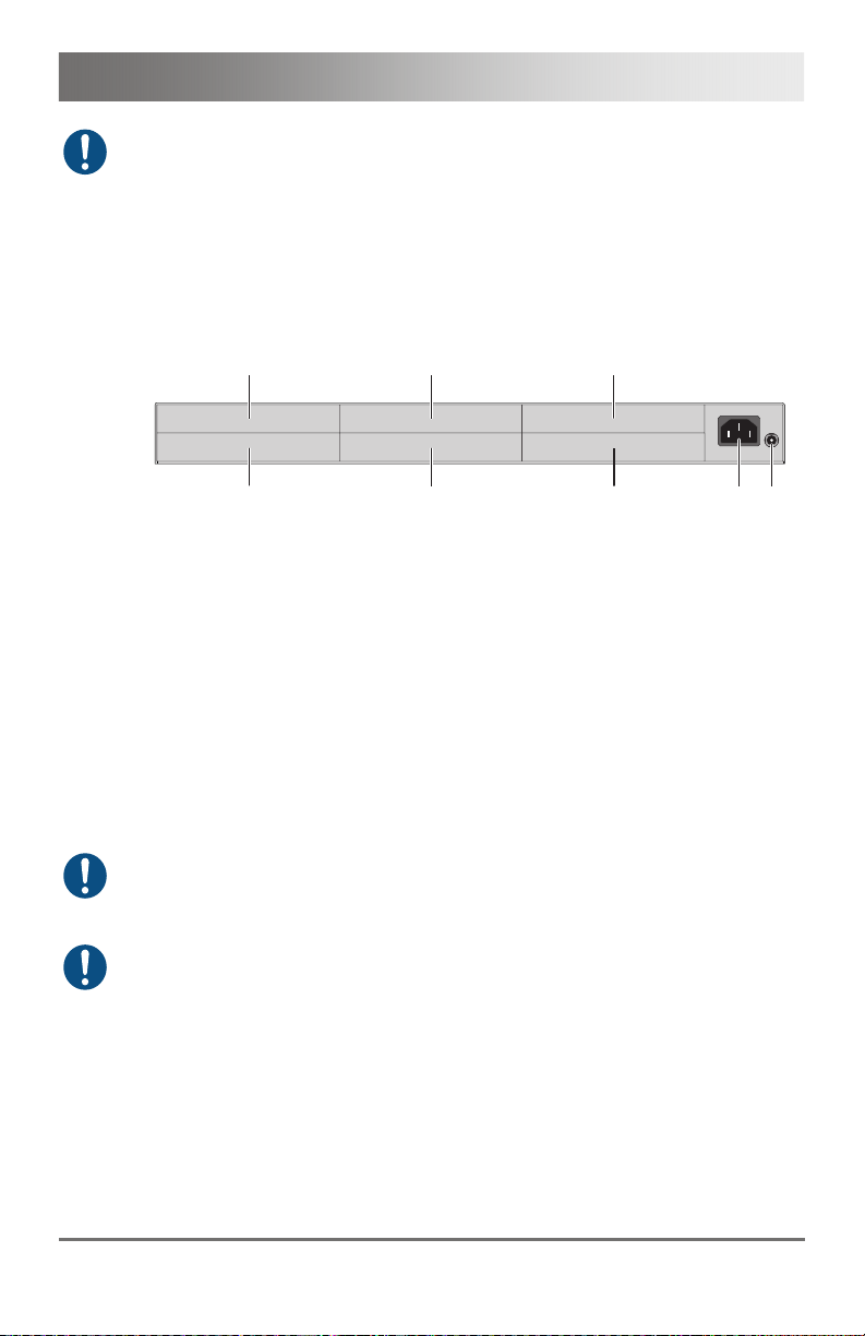
3.6.3 4-fold Vario Chassis 474-BODY4/4R
CPU and CON Unit
4
1
5
2
Rear View
1 Slot for modules #3
2 Slot for modules #1
3 Connect to 5VDC power supply (standard)
4 Slot for modules #4
5 Slot for modules #2
6 Connect to 5VDC power supply (redundancy, optional)
6
3
16 2013-12-06
Page 17
Description
For operation with three KVM Extender CON modules and a USB 2.0
CON module in a 4-fold vario chassis, an external power supply unit at the
second 5VDC connector is explicitly necessary. In this case, redundancy
is inapplicable.
Pos: 13 /806-IHSE/Beschreibung/Geräteansichte n/474-xx/6-fac h Vario-Gehäuse 474-BODY6 R @ 6\mod_1304580442488_6. doc @ 50894 @ 3 @ 1
3.6.4 6-fold Vario Chassis 474-BODY6R
CPU and CON Unit
Rear View
1 Slot for modules #5
2 Slot for modules #3
3 Slot for modules #1
4 Connect to power supply (standard)
5 Connect to 5VDC power supply (standard)
6 Slot for modules #6
7 Slot for modules #4
8 Slot for modules #2
For operation with KVM Extender modules in a 6-fold vario chassis, an
external power supply unit at the 5VDC connector is explicitly necessary.
In this case, redundancy is inapplicable.
The 6-fold vario chassis is not equipped with a fuse on primary side.
Therefore the protection against excessive currents has to be provided by
the electrical installation of the building.
Pos: 14 /806-IHSE/Beschreibung/Geräteansichte n/481-xx/6-fac h Vario-Gehäuse 474-BODY6B P @ 9\mod_1367827188730_6. doc @ 71694 @ 3 @ 1
6
1
7
2
8
3
5
4
2013-12-06 17
Page 18
Draco KVM Extender
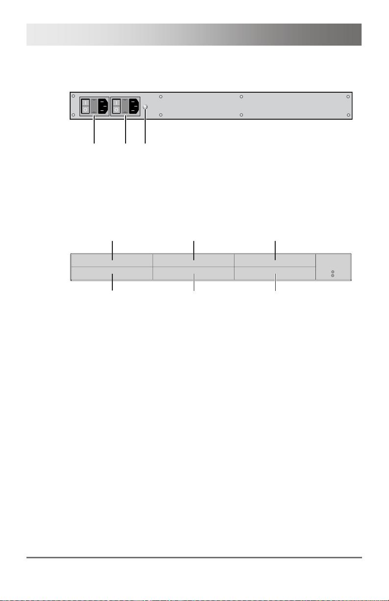
3.6.5 6-fold Vario Chassis 474-BODY6BP
CPU and CON Unit
Pos: 15 /806-IHSE/zz_Layout/Seitenumbruch @ 8\ mod_1348581820516_0.doc @ 69462 @ @ 1
123
Front View
1 Connect to power supply 1
2 Connect to power supply 2 (redundancy)
3 Grounding
Rear View
1 Slot for modules #5
2 Slot for modules #3
3 Slot for modules #1
4 Slot for modules #6
5 Slot for modules #4
6 Slot for modules #2
45
1
2
6
3
18 2013-12-06
Page 19
Description
Pos: 16 /806-IHSE/Beschreibung/Geräteansichte n/474-xx/21-fac h Vario-Gehäuse 474-BODY 21R @ 8\mod_1348579151346_ 6.doc @ 69400 @ 3 @ 1
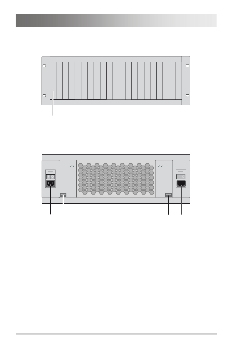
3.6.6 21-fold Vario Chassis 474-BODY21R
CPU and CON Unit
Pos: 17 /806-IHSE/zz_Layout/Seitenumbruch @ 8\ mod_1348581820516_0.doc @ 69462 @ @ 1
1
Rear View
1 Slots for modules #1 - #21
2
1
Front View
1 Connect to power supply 2
2 Locking for power supply 2 (redundancy)
3 Locking for power supply 1 (standard)
4 Connect to power supply 1
3
4
2013-12-06 19
Page 20
Draco KVM Extender
Pos: 18 /806-IHSE/Beschreibung/Geräteansic hten/474-xx/Typ L- / R474-BDHC / -B2HC @ 9\mod_1373959428603_6.doc @ 77301 @ 3 @ 1
3.6.7 Model L- / R474-BDHC / -B2HC
CPU Module CON Module
12
3
4
12
Rear View Rear View
1 Service port
2 Connect to interconnect cable
3 To CPU: USB-HID
4 To CPU: DMS-59
Pos: 19 /806-IHSE/Beschreibung/Geräteansichte n/474-xx/Typ L- / R474-BDHS/X / -B2HS/X @ 9\mod_137395 9653960_6.doc @ 77322 @ 3 @ 1
1 Service port
2 Connect to interconnect cable
3 Connect to USB-HID devices
4 Connect to monitor(s) (DMS-59)
3.6.8 Model L- / R474-BDHS/X / -B2HS/X
CPU Module CON Module
3
4
12
1 Service port
2 Connect to interconnect cable
3 Connect to USB-HID devices
4 Connect to monitor(s) (DMS-59)
Rear View Rear View
1 Service port
2 Connect to interconnect cable
3 To CPU: USB-HID
4 To CPU: DMS-59
Pos: 20 /806-IHSE/Beschreibung/Geräteansichte n/482-xx/Typ L- / R474-BDHCR / -B2HCR @ 10\mod_1385646 648377_6.doc @ 103062 @ 3 @ 1
12
3
3
4
4
20 2013-12-06
Page 21
Description
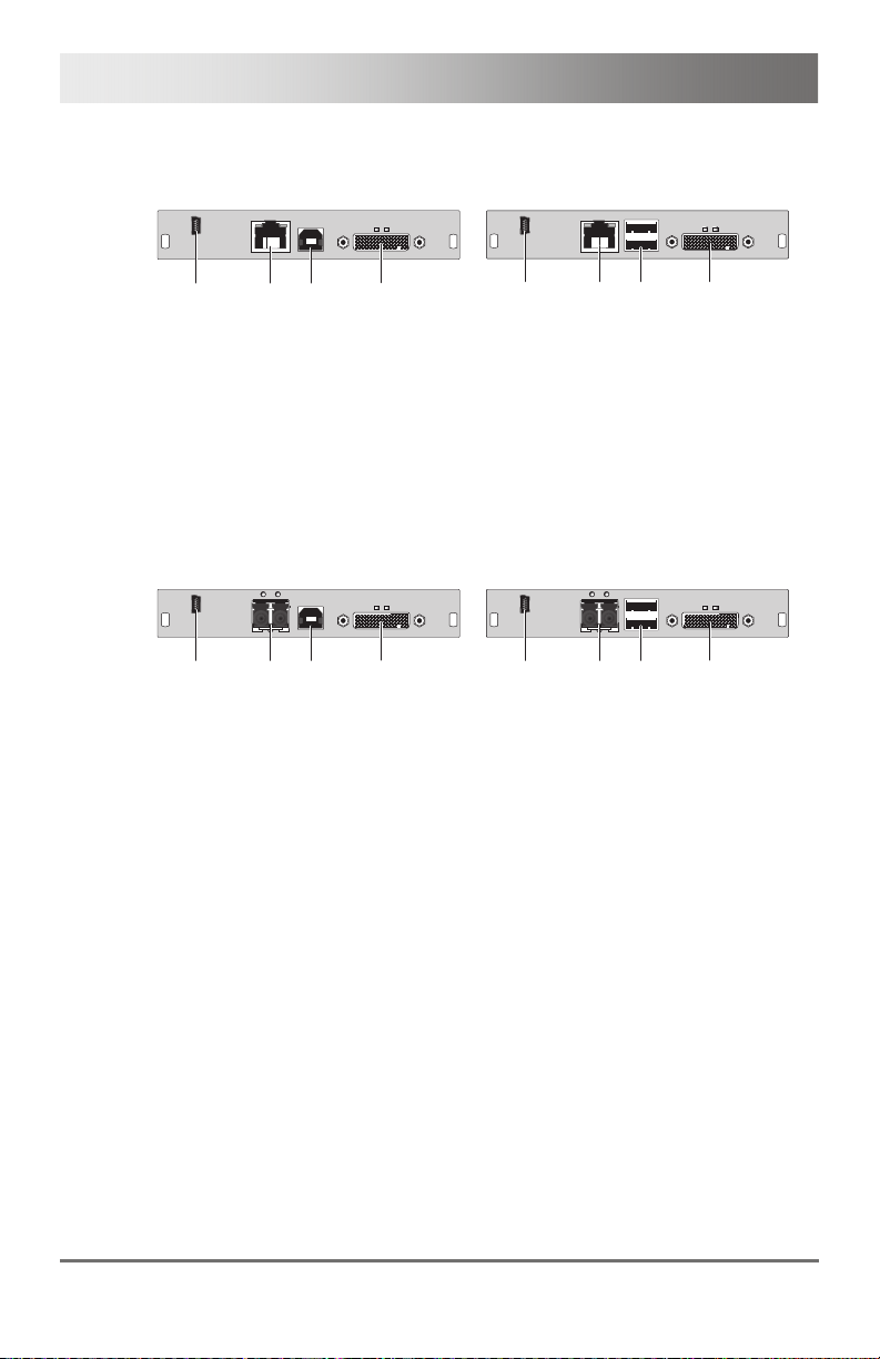
3.6.9 Model L- / R474-BDHCR / -B2HCR
CPU Module CON Module
12
3
45
12
3
Rear View Rear View
1 Service port
2 Connect to interconnect cable 1
3 Connect to interconnect cable 2
4 To CPU: USB-HID
5 To CPU: DMS-59
Pos: 21 /806-IHSE/Beschreibung/Geräteansichte n/482-xx/Typ L- / R474-BDHS/XR / -B2HS/XR @ 10\mod_1 385646649157_6.doc @ 103086 @ 3 @ 1
1 Service port
2 Connect to interconnect cable 1
3 Connect to interconnect cable 2
4 Connect to USB-HID devices
5 Connect to monitor(s) (DMS-59)
3.6.10 Model L- / R474-BDHS/XR / -B2HS/XR
CPU Module CON Module
12
3
45
12
3
Rear View Rear View
1 Service port
2 Connect to interconnect cable 1
3 Connect to interconnect cable 2
4 To CPU: USB-HID
5 To CPU: DMS-59
Pos: 22 /806-IHSE/Beschreibung/Geräteansichte n/474-xx/Typ L- / R474-BXH @ 6\mod_13045835076 45_6.doc @ 50984 @ 3 @ 1
1 Service port
2 Connect to interconnect cable 1
3 Connect to interconnect cable 2
4 Connect to USB-HID devices
5 Connect to monitor(s) (DMS-59)
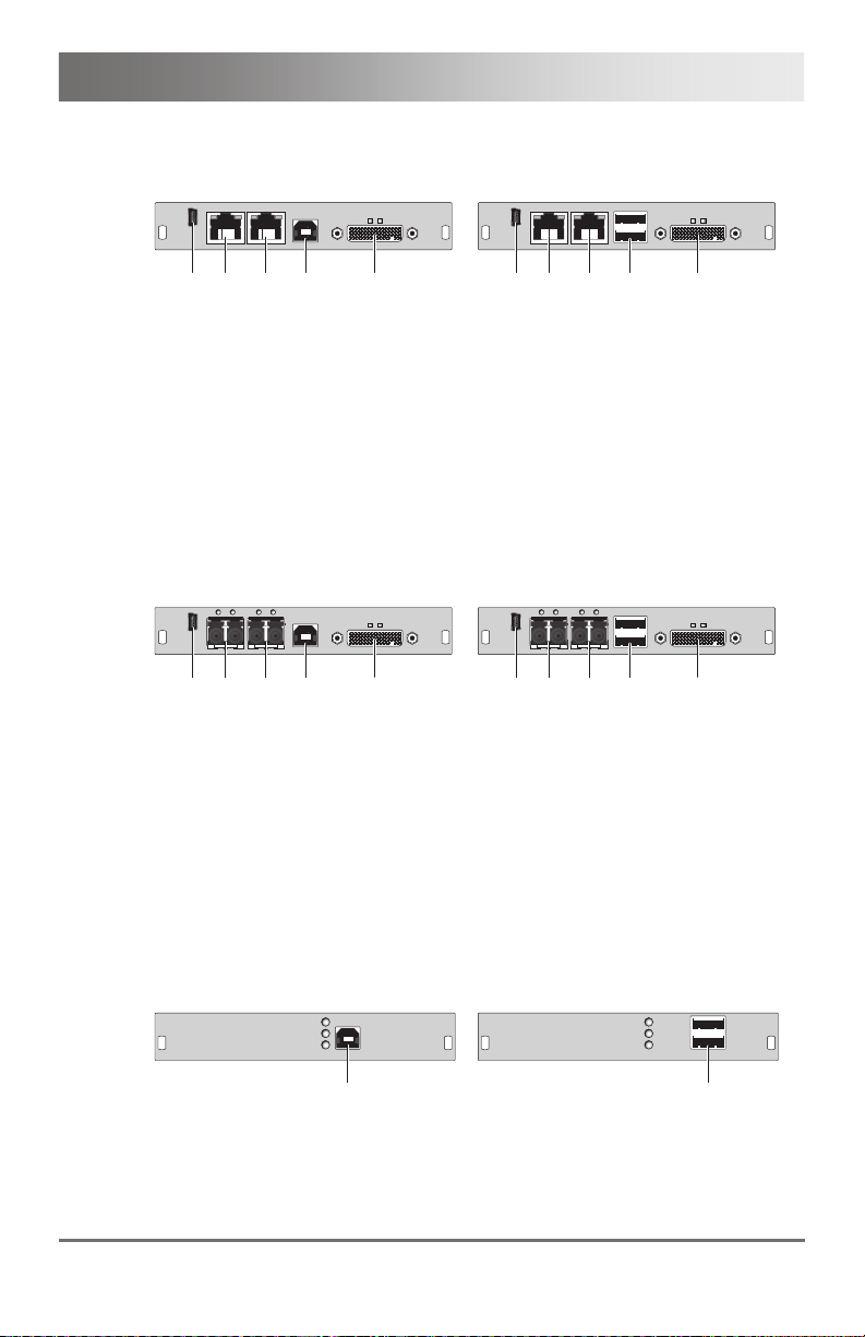
3.6.11 Model L- / R474-BXH
45
45
CPU Module CON Module
1
1
Rear View Rear View
1 To CPU: USB-HID 1 Connect to USB-HID devices
Pos: 23 /806-IHSE/Beschreibung/Geräteansichten/ 474-xx/Typ L- / R474-BXE @ 7\mod_1331 798896275_6.doc @ 58110 @ 3 @ 1
2013-12-06 21
Page 22
Draco KVM Extender
3.6.12 Model L- / R474-BXE
CPU Module CON Module
1
Rear View Rear View
1 To CPU: USB 2.0 1 Connect to USB 2.0 devices
Pos: 24 /806-IHSE/Beschreibung/Geräteansichte n/474-xx/Typ L- / R474-BUE @ 7\mod_13317990387 17_6.doc @ 58130 @ 3 @ 1
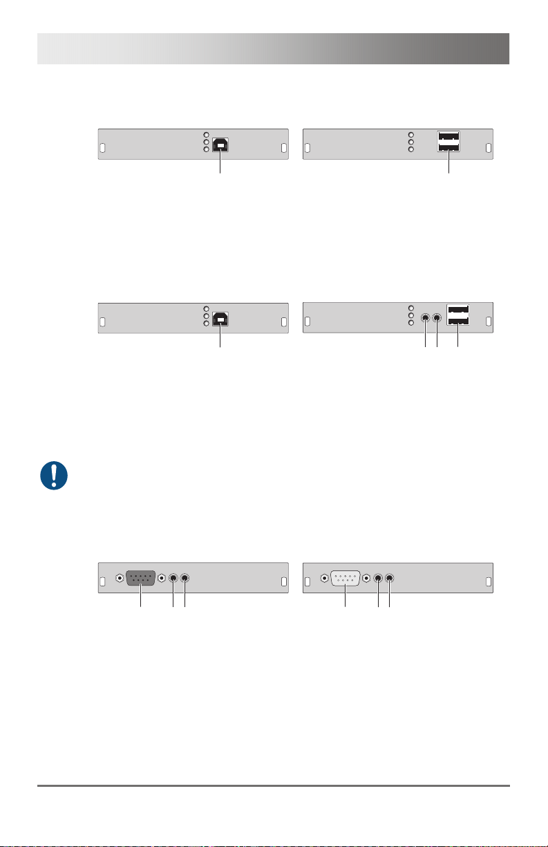
3.6.13 Model L- / R474-BUE
CPU Module CON Module
1
Rear View Rear View
1 To CPU: USB 2.0 1 Audio IN
When using USB audio within a KVM matrix, instant switching is not
possible due to the deregistration and registration process of the USB.
Pos: 25 /806-IHSE/Beschreibung/Geräteansichten/ 474-xx/Typ L- / R474-BAX @ 6\mod_1304 583540285_6.doc @ 51002 @ 3 @ 1
3.6.14 Model L- / R474-BAX
CPU Module CON Module
23
1
1
2 Audio OUT
3 Connect to USB 2.0 devices
1
3
2
123
Rear View Rear View
1 Connect to serial (D-Sub 9)
2 Audio IN
3 Audio OUT
Pos: 26 /806-IHSE/Beschreibung/Geräteansichten/ 474-xx/Typ L- / R474-BAP @ 9\mod_1362 472648439_6.doc @ 71250 @ 3 @ 1
1 Connect to serial (D-Sub 9)
2 Audio IN
3 Audio OUT
22 2013-12-06
Page 23
Description
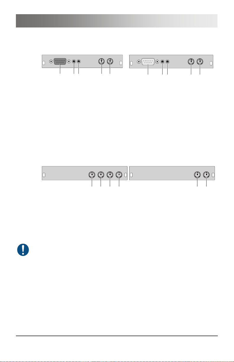
3.6.15 Model L- / R474-BAP
CPU Module CON Module
1
3
2
45
Rear View Rear View
1 Connect to serial (D-Sub 9)
2 Audio IN
3 Audio OUT
4 To CPU: PS/2 mouse
5 To CPU: PS/2 keyboard
Pos: 27 /806-IHSE/Beschreibung/Geräteansichten/ 474-xx/Typ L- / R474-BXP @ 8\mod_1348 579797358_6.doc @ 69420 @ 3 @ 1
3.6.16 Model L- / R474-BXP
CPU Module CON Module
1
234
Rear View Rear View
1 Connect to local PS/2 mouse
2 Connect to local PS/2 keyboard
3 To CPU: PS/2 mouse
4 To CPU: PS/2 keyboard
The upgrade module L- / R474-BXP is only available in combination with
the upgrade modules L- / R474-BAX and –BAH. A separate slot is
required for each module.
Pos: 28 /806-IHSE/Beschreibung/Geräteansichte n/474-xx/Typ L- / R474-BDX @ 6\mod_13045835778 01_6.doc @ 51020 @ 3 @ 1
123
1 Connect to serial (D-Sub 9)
2 Audio IN
3 Audio OUT
4 Connect to PS/2 mouse
5 Connect to PS/2 keyboard
1 Connect to PS/2 mouse
2 Connect to PS/2 keyboard
45
1
2
2013-12-06 23
Page 24
Draco KVM Extender
3.6.17 Model L- / R474-BDX
CPU Module CON Module
Pos: 29 /806-IHSE/zz_Layout/Seitenumbruch @ 8\ mod_1348581820516_0.doc @ 69462 @ @ 1
1
3
2
1
Rear View Rear View
1 S/PDIF input (RCA)
2 AES/EBU input (Mini-XLR)
3 S/PDIF input (TOSLINK)
1 S/PDIF output (RCA)
2 AES/EBU output (Mini-XLR)
3 S/PDIF output (TOSLINK)
3
2
24 2013-12-06
Page 25

Description
Pos: 30 /806-IHSE/Beschreibung/Geräteansichte n/474-xx/Typ L- / R474-BAH @ 6\mod_13045836117 85_6.doc @ 51038 @ 3 @ 1
3.6.18 Model L- / R474-BAH
CPU Module CON Module
1
3
2
4
Rear View Rear View
1 Connect to serial (D-Sub 9)
2 Audio IN
3 Audio OUT
4 To CPU: USB-HID
Pos: 31 /806-IHSE/Beschreibung/Geräteansichte n/474-xx/Typ L- / R474-BDH @ 6\mod_130458364645 7_6.doc @ 51056 @ 3 @ 1
3.6.19 Model L- / R474-BDH
CPU Module CON Module
Pos: 32 /806-IHSE/zz_Layout/Seitenumbruch @ 8\ mod_1348581820516_0.doc @ 69462 @ @ 1
1
Rear View Rear View
1 S/PDIF input (RCA)
2 AES/EBU input (Mini-XLR)
3 S/PDIF input (TOSLINK)
4 To CPU: USB-HID
3
2
4
123
4
1 Connect to serial (D-Sub 9)
2 Audio IN
3 Audio OUT
4 Connect to USB-HID devices
1
3
2
4
1 S/PDIF output (RCA)
2 AES/EBU output (Mini-XLR)
3 S/PDIF output (TOSLINK)
4 Connect to USB-HID devices
2013-12-06 25
Page 26

Draco KVM Extender
Pos: 33 /806-IHSE/Beschreibung/Geräteansichten/ 474-xx/Typ L- / R474-BAE @ 7\mod_1331 799164939_6.doc @ 58150 @ 3 @ 1
3.6.20 Model L- / R474-BAE
CPU Module CON Module
1
3
2
4
Rear View Rear View
1 Connect to serial (D-Sub 9)
2 Audio IN
3 Audio OUT
4 To CPU: USB 2.0
Pos: 34 /806-IHSE/Beschreibung/Geräteansichte n/474-xx/Typ L- / R474-BDE @ 8\mod_13485802724 66_6.doc @ 69440 @ 3 @ 1
3.6.21 Model L- / R474-BDE
CPU Module CON Module
Pos: 35 /806-IHSE/zz_Layout/Seitenumbruch @ 8\ mod_1348581820516_0.doc @ 69462 @ @ 1
1
Rear View Rear View
1 S/PDIF input (RCA)
2 AES/EBU input (Mini-XLR)
3 S/PDIF input (TOSLINK)
4 To CPU: USB 2.0
3
2
4
123
1 Connect to serial (D-Sub 9)
2 Audio IN
3 Audio OUT
4 Connect to USB 2.0 devices
1
3
2
1 S/PDIF output (RCA)
2 AES/EBU output (Mini-XLR)
3 S/PDIF output (TOSLINK)
4 Connect to USB 2.0 devices
4
4
26 2013-12-06
Page 27

Description
Pos: 36 /806-IHSE/Beschreibung/Geräteansichte n/474-xx/Typ L- / R474-BDD @ 6\mod_130458369642 6_6.doc @ 51074 @ 3 @ 1
3.6.22 Model L- / R474-BDD
CPU Module CON Module
1
3
2
5
4
6
Rear View Rear View
1 S/PDIF input (RCA)
2 AES/EBU input (Mini-XLR)
3 S/PDIF input (TOSLINK)
4 S/PDIF output (RCA)
5 AES/EBU output (Mini-XLR)
6 S/PDIF output (TOSLINK)
Pos: 37 /806-IHSE/Beschreibung/Geräteansichte n/474-xx/Typ L- / R474-BDA @ 6\mod_13045837534 26_6.doc @ 51092 @ 3 @ 1
3.6.23 Modell L- / R474-BDA
CPU Module CON Module
Pos: 38 /806-IHSE/zz_Layout/Seitenumbruch @ 8\ mod_1348581820516_0.doc @ 69462 @ @ 1
1
Rear View Rear View
1 S/PDIF input (RCA)
2 AES/EBU input (Mini-XLR)
3 S/PDIF input (TOSLINK)
4 Connect to serial (D-Sub 9)
5 Audio IN
6 Audio OUT
3
2
5
4
1
3
2
1 S/PDIF output (RCA)
2 AES/EBU output (Mini-XLR)
3 S/PDIF output (TOSLINK)
4 S/PDIF input (RCA)
5 AES/EBU input (Mini-XLR)
6 S/PDIF input (TOSLINK)
6
1
3
2
1 S/PDIF output (RCA)
2 AES/EBU output (Mini-XLR)
3 S/PDIF output (TOSLINK)
4 Connect to serial (D-Sub 9)
5 Audio IN
6 Audio OUT
5
4
6
5
4
6
2013-12-06 27
Page 28

Draco KVM Extender
Pos: 39 /806-IHSE/Beschreibung/Geräteansichte n/474-xx/Typ L- / R474-BXTC @ 6\mod_13045837845 82_6.doc @ 51110 @ 3 @ 1
3.6.24 Modell L- / R474-BXTC
CPU Module CON Module
12
3
Rear View Rear View
1 Service port
2 Connect to interconnect cable
3 To CPU: USB 2.0
Pos: 40 /806-IHSE/Beschreibung/Geräteansichte n/474-xx/Typ L- / R474-BXTS @ 6\mod_1304583818 676_6.doc @ 51128 @ 3 @ 1
3.6.25 Modell L- / R474-BXTS
CPU Module CON Module
3
Pos: 41 /806-IHSE/zz_Layout/Seitenumbruch @ 8\ mod_1348581820516_0.doc @ 69462 @ @ 1
12
Rear View Rear View
1 Service port
2 Connect to interconnect cable
3 To CPU: USB 2.0
It is only allowed to use one USB 2.0 CON module per chassis.
12
3
4
1 Service port
2 Connect to interconnect cable
3 Connect to USB 2.0 devices
12
3
4
1 Service port
2 Connect to interconnect cable
3 Connect to USB 2.0 devices
28 2013-12-06
Page 29

Description
Pos: 42 /806-IHSE/Beschreibung/Diagnose LEDs/ UEB_Diagnose_LEDs @ 6\mod_1304 584004723_6.doc @ 51146 @ @ 1
3.7 Status LEDs
Pos: 43 /806-IHSE/Beschreibung/Diagnose LEDs/482- xx @ 10\mod_1385650419 587_6.doc @ 103110 @ 3 @ 1
3.7.1 Status KVM Extender Module
The KVM Extender module is fitted with a multi color LED on both sides
for overall status indication and with two further LEDs on the back side for
indication of the connection status.
CPU Module CON Module
3 421 21
3 42121
Rear View Rear View
LED 1 and 2: Connection Status
Pos. LED Status Description
Failure LED
(green)
Status LED
(green)
Off Connection available 1
On or
Flashing
Connection failure (flashing for about
20 s following a connection failure)
Flashing No connection via interconnect cable 2
On Connection available
LED 3: USB and Video Status Channel 1
LED 4: USB and Video Status Channel 2
LED color Description
Red Device ready
Violet
Connection and USB signal (interconnect) available
Green Connection and video signal available
3 421 21
3 42121
Light Blue
Pos: 44 /806-IHSE/Beschreibung/Diagnose LEDs/474- xx/Diagnose Zusatz modul Digital-Audio @ 6\mod_1304584173301_ 6.doc @ 51201 @ 3 @ 1
Connection, USB and video signal available
(operating status)
2013-12-06 29
Page 30

Draco KVM Extender
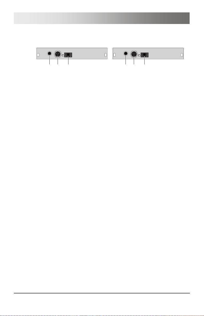
3.7.2 Status Upgrade Module Digital Audio
The upgrade module digital audio is fitted with a further multi-color LED on
the rear side for indication of the connection status:
CPU Module CON Module
Rear View Rear View
LED 1: Digital Audio Status
LED color Description
Red No signal
Light Blue CPU Unit: S/PDIF signal (RCA) available
Violet CPU Unit: AES/EBU signal (Mini-XLR) available
Blue CPU Unit: S/PDIF signal (TOSLINK) available
Green CON Unit: Signal available
Pos: 45 /806-IHSE/Beschreibung/Diagnose LEDs/474- xx/Diagnose Zusatz modul USB-HID @ 6\mod_130458 4220145_6.doc @ 51219 @ 3 @ 1
1
1
30 2013-12-06
Page 31

Description
3.7.3 Status Upgrade Module USB-HID
The upgrade module USB-HID is fitted with three further LEDs on the rear
side for indication of the connection status:
CPU Module CON Module
Rear View Rear View
Pos. LED Status Description
1, 2
3
Pos: 46 /806-IHSE/Beschreibung/Diagnose LEDs/474- xx/Diagnose Zusatz modul USB 2.0 embedded @ 7\mod _1331803265129_6.doc @ 58231 @ 3 @ 1
1
23
Device LED
(orange)
Status LED
(orange)
23
1
Off
No USB-HID device or not supported
USB device connected
Flashing
USB-HID device active
fast
On
USB-HID device ready or KVM
Extender in command mode
Off No power supply voltage
CPU Unit: KVM Extender in
command mode or no connection
CON Unit: Keyboard in command
mode
Flashing
slowly
Flashing
CON Unit: KVM Extender in command
mode or no connection
Operating status
fast
2013-12-06 31
Page 32

Draco KVM Extender
3.7.4 Status Upgrade module USB 2.0 embedded
The upgrade module USB 2.0 embedded is fitted with three further LEDs
on the rear side for indication of the connection status:
CPU Module CON Module
Rear View Rear View
Pos. LED Status Description
2
3
Pos: 47 /806-IHSE/Beschreibung/Diagnose LEDs/474- xx/Diagnose Zusatz modul USB 2.0 @ 6\mod_13045842 54816_6.doc @ 51237 @ 3 @ 1
1
23
Status LED
(green)
Status LED
(green)
Status LED
(green)
Off No USB 2.0 device connected 1
Flashing
slowly
Off
Flashing
slowly
On
Off
On
23
1
USB 2.0 device connected
No connection to source (computer,
CPU) available
Connection to source (computer,
CPU) available
No USB 2.0 device connected
Connection to source (computer,
CPU) available
USB 2.0 device(s) connected
No connection between CON and CPU
module
Connection between CON and CPU
module available
32 2013-12-06
Page 33

Description
3.7.5 Status Upgrade Module USB 2.0
The upgrade module USB 2.0 is fitted with a multi color LED on both sides
for overall status indication and with two further LEDs on the back side for
indication of the connection status.
CPU Module CON Module
Pos: 48 /806-IHSE/Installation/UEB_Installa tion @ 5\mod_1278574971589 _6.doc @ 41768 @ 1 @ 1
12
3
3
12
Rear View Rear View
Pos. LED Status Description
Failure LED
(green)
Status LED
(green)
Off Connection available 1
On or
Flashing
Connection failure (flashing for about
20 s following a connection failure)
Off No connection via interconnect cable 2
On Connection available
LED 3: USB 2.0 Status
LED color Description
Red
Device ready
Green
Only connection available, no USB 2.0 signal
Green /
light blue
Connection available, no USB 2.0 device
connected
flashing
Light blue
Connection and USB 2.0 signal available
(operating status)
12
12
3
3
2013-12-06 33
Page 34

Draco KVM Extender
4 Installation
Pos: 49 /806-IHSE/Installation/Lieferumfang pr üfen/482-xx @ 10\mod_13 85650684328_6.doc @ 103134 @ 2 @ 1
4.1 Package Contents
Your extender package contains the following items:
KVM Extender:
KVM Extender pair (CPU Unit and CON Unit) in the vario chassis
1x (redundancy 2x) 5VDC international power supply unit per KVM
Extender unit
1x (redundancy 2x) country specific power cord
Quick Setup
USB cable (1.8 m, type A to type B)
Additional content for KVM Extender module Dual Link (replaces
DVI-D cable):
2x DVI to DMS-59 video cable 1.8 m (DVI-D Dual Link connector to
DMS-59 connector)
Additional content for KVM Extender module Dual Head (replaces
DVI-D cable):
2x DVI to DMS-59 video cable 0.3 m (DVI-D Dual Link connector to
DMS-59 connector)
34 2013-12-06
Page 35

Installation
Additional content for upgrade module Analog Audio / Serial:
Serial cable (1.8 m, D-Sub 9 male connector)
Stereo jack cable (1.6 m, 3.5 mm male connector)
Additional content for upgrade module serial (RS422):
Serial cable (1.8 m, D-Sub 9 male connector)
Additional content for upgrade module Digital Audio:
RCA cable (2.5 m, Cinch male connector)
TOSLINK cable (1.8 m, F05 male connector)
Additional content for upgrade module USB-HID:
USB cable (1.8 m, USB type A to type B)
Additional content for upgrade module PS/2:
2x PS/2 cable (1.8 m, 6-pole connector)
Additional content for upgrade module USB 2.0 embedded:
USB cable (1.8 m, USB type A to type B)
Additional content for upgrade module USB 2.0:
USB cable (1.8 m, USB type A to type B)
2013-12-06 35
Page 36

Draco KVM Extender
If anything is missing, contact your dealer.
Pos: 50 /806-IHSE/Installation/System anschließ en/482-xx @ 10\mod_13 85650859088_6.doc @ 103158 @ 233 @ 1
4.2 System Setup
First time users are recommended to setup the system with the CPU Unit
and the CON Unit in the same room as a test setup. This will allow you to
identify and solve any cabling problems, and experiment with your system
more conveniently.
Please verify that interconnect cables, interfaces, and handling of the
4.2.1 KVM Extender Setup
devices comply with the requirements (see Chapter
1. Switch off all devices.
CON Unit Installation
2. Connect your monitor(s), keyboard and mouse to the CON Unit.
3. Connect the CON Unit with the interconnect cable(s).
4. Connect the 5VDC power supply to the CON Unit.
CPU Unit Installation
5. Connect the source (computer, CPU) with the supplied cables to the
CPU Unit. Please ensure the cables are not strained.
6. Connect the CPU Unit to the interconnect cable(s).
7. Connect the 5VDC power supply to the CPU Unit.
8. Power up the system.
To power up the system, the following sequence is recommended:
Monitor – CON Unit – CPU Unit – source.
7, Page 51).
36 2013-12-06
Page 37

Installation
4.2.2 Setup of Upgrade Modules
The modules can be hot plugged.
Upgrade Module Analog Audio / Serial:
1. Connect the audio source with the CPU Unit (e.g. CPU audio output
with audio input, CPU audio input with audio output).
2. Connect the audio output at the CON Unit with headphones or
suitable speakers.
3. Connect the audio input at the CON Unit with a suitable microphone.
Upgrade Module Serial RS422:
1. Connect the CPU to the CPU Unit by using the serial cable.
2. Connect the CON Unit to the serial connector of the input device.
Upgrade Module Digital Audio:
1. Connect the digital audio source with the suitable audio input of the
CPU Unit.
2. Connect the audio output of the CON Unit with suitable speakers or
audio amplifiers.
If several active sources are connected, Mini-XLR input takes priority.
The audio signal is available at all outputs.
Upgrade Module USB-HID:
1. Connect the CPU with the CPU Unit (USB-HID 2).
2. Connect the USB-HID devices with the CON Unit (Connect to
USB-HID devices 2).
Upgrade Module PS/2:
1. Connect the CPU to a CPU unit via proved PS/2 cables for PS/2
devices.
2. Connect the PS/2 devices to the CON unit (Connector to PS/2
devices).
2013-12-06 37
Page 38

Draco KVM Extender
Upgrade Module USB 2.0 Embedded:
1. Connect the CPU with the CPU Unit (USB 2.0).
2. Connect the USB 2.0 devices with the CON Unit (Connect to
USB 2.0 devices).
Upgrade Module USB 2.0:
1. Connect the CPU with the CPU Unit (USB 2.0).
2. Connect the USB 2.0 devices with the CON Unit (Connect to
USB 2.0 devices).
Pos: 51 /806-IHSE/Installation/Installatio nsbeispiele/UEB_I nstallationsbei spiele @ 5\mod_12785815648 70_6.doc @ 42759 @ 2 @ 1
4.3 Example Applications
Pos: 52 /806-IHSE/Installation/Installatio nsbeispiele/477- xx_COMP @ 5\mod_12911242643 28_6.doc @ 44767 @ @ 1
This section illustrates typical installations of KVM Extenders:
KVM Extender (Single-Head)
1
2
3
4
5
38 2013-12-06
Page 39

Installation
1
2
3
4
5
KVM Extender (Single-Head with Digital / Analog Audio)
1
2
3
4
5
6
KVM Extender (Dual-Head with 4x USB-HID)
1 Source (computer, CPU)
2 KVM Extender CPU Unit
3 Interconnect cable
4 KVM Extender CON Unit
5 Console (monitor, keyboard, mouse)
6 Second monitor (option, only with Dual-Head devices)
7 USB 2.0 devices (option, only with 2x USB 2.0 devices)
8 Audio sink (optional, only with devices with Analog Audio / Serial
option or Digital Audio option)
8
7
2013-12-06 39
Page 40

Draco KVM Extender
2 x HI D
Full Speed
2.0
High Speed
2.0
2 x HI D
Full Speed
2.0
High Speed
2.0
Pos: 53 /806-IHSE/Installation/Zusatzmodule/ 474-xx_Zusatzmodu le @ 9\mod_137396047483 5_6.doc @ 77366 @ 2 @ 1
4.4 Overview Upgrade Modules
This section illustrates an overview of the available types of upgrade
modules for the KVM Extender.
Pos: 54 /806-IHSE/Konfiguration/UEB_Konfigur ation @ 5\mod_1278575517 073_6.doc @ 41846 @ 1 @ 1
L474-BXH
L474-BXE
L474-BAX
L474-BAP
L474-BDX
L474-BSX
L474-BXTC
Overview Upgrade Modules
2 x HID
2 x HID
2.0
2.0
Full Speed
Full Speed
Analog
Audio
+RS232
Analog
Audio
/
+RS232
Analog
Audio
+RS422
2.0
2.0
High Speed
High Speed
CPU Unit
CON Unit
R474-BXH
R474-BXE
R474-BAX
R474-BAP
R474-BDX
R474-BSX
R474-BXTC
2 x HID
2 x HID
2.0
2.0
Full Speed
Full Speed
Analog
Audio
+RS232
Analog
Audio
/
+RS232
Analog
Audio
+RS422
2.0
2.0
High Speed
High Speed
40 2013-12-06
Page 41

Configuration
5 Configuration
Pos: 55 /806-IHSE/Konfiguration/Übertragungs parameter/477- xx @ 5\mod_1278937002401_6. doc @ 43075 @ @ 1
5.1 Transmission Parameters
The device operates with a proprietary compression method.
In default configuration, the device adapts dynamically to monitor
resolution and image content. This configuration is suitable for almost all
conditions and should only be modified if image quality is not fully
satisfactory.
In exceptional cases there can appear detached "frame droppings" (loss
of single pictures) or color effects.
Pos: 56 /806-IHSE/Konfiguration/DDC-Einstellungen/48 2-xx @ 10\mod_138565110 7839_6.doc @ 103182 @ 2 @ 1
5.2 DDC Settings
By default, the device transmits the factory preset DDC information to the
CPU. This information is suitable in most cases.
The download of the DDC information of the console monitor can be
performed during normal operation (see Chapter
6.1, Page 48).
For special requirements, DDC information can be retrieved and uploaded
as a binary file at both the CPU Unit and the CON Unit.
Connect your computer with a USB mini cable to the service port of the
CPU Unit or CON Unit.
The data area of the unit is now accessible as a flash drive "Extender".
Uploading DDC Information
Copy the binary file containing your specific DDC information to the flash
drive of the CPU Unit or CON Unit.
The current DDC information is replaced.
Retrieving DDC Information
Copy the file "DDC-EDID.bin" on the flash drive of the CPU Unit to your
computer.
To open the binary file, you have to install a suitable software, e.g.
WinDDCwrite, on your computer. Contact your dealer for this purpose.
Reset to Factory DDC Information
Delete the file called "DDC-EDID.bin" on the flash drive of the CPU Unit.
By deleting this file, the factory DDC Information is restored.
2013-12-06 41
Page 42

Draco KVM Extender
5.3 Command Mode
During normal use, the console keyboard functions in the usual manner.
However, for all KVM Extenders with USB-HID support, you can set the
keyboard into a Command Mode by using a specific 'Hot Key' sequence.
While in Command Mode, several functions are performed via keyboard
commands. To exit Command Mode, press <Esc>.
While in Command Mode, the LEDs Shift and Scroll on the console
keyboard will flash.
In Command Mode normal keyboard and mouse operation will cease.
Only selected keyboard commands are available.
If there is no keyboard command executed within 10 s after activating
Command Mode, it will be automatically deactivated.
The following table lists the keyboard commands to enter and to exit
Command Mode and to change the 'Hot Key' sequence:
Function Keyboard Command
Enter Command Mode (default) 2x <Left Shift> / ('Hot Key')
Exit Command Mode <Esc>
Change 'Hot Key' sequence <current 'Hot Key'>, <c>,
<Key> + <Key> Press keys simultaneously
<Key>, <Key> Press keys successively
2x <Key> Press key quickly, twice in a row
(similar to a mouse double-click)
<new 'Hot Key' code>, <Enter>
Until 2011-30-09:
<Left Ctrl> + <Left Shift> + <c>,
<'Hot Key' Code>, <Enter>
42 2013-12-06
Page 43

Configuration
The 'Hot Key' sequence to enter Command Mode can be changed. The
following table lists the 'Hot Key' Codes for the available key sequences:
'Hot Key' Code 'Hot Key'
0 Freely selectable (from 2012-01-12)
2 2x <Scroll>
3 2x <Left Shift>
4 2x <Left Ctrl>
5 2x <Left Alt>
6 2x <Right Shift>
7 2x <Right Ctrl>
8 2x <Right Alt>
Set freely selectable 'Hot Key' (exemplary)
In order to set a freely selectable 'Hot Key' (e.g. 2x <Space>), use the
following keyboard sequence:
<current 'Hot Key'>, <c>, <0>, <Space>, <Enter>
Reset 'Hot Key'
In order to set a 'Hot Key' back to default settings of the extender, press
the key combination <Right Shift> + <Del> within 5 s after switching on the
CON unit or plugging in a keyboard.
Pos: 58 /806-IHSE/Konfiguration/USB-HID-Ghosti ng/K477_USB-HID- Ghosting @ 9\mod_136240 4683851_6.doc @ 71192 @ 2 @ 1
5.4 USB-HID Ghosting
This function allows storing the specific keyboard and mice descriptors
(device descriptions) into the CPU unit. This permanent storage prevents
the registration and deregistration process of keyboard and mouse on an
operating system each time, if there is a shared use of a source
(computer, CPU) by two or more consoles within a KVM matrix.
The following table lists the keyboard commands for the configuration of
USB-HID Ghosting:
2013-12-06 43
Page 44

Draco KVM Extender
Function Keyboard Command
Writing the device descriptions of
the input devices connected to the
CON Unit into the CPU Unit.
Activating the emulation in the
CPU Unit.
Activating the emulation of
already stored device descriptions
in the CPU Unit
Deactivating the emulation of
active device descriptions in the
CPU Unit. The input devices
connected to the CON Unit will be
now passed transparently to the
source (computer, CPU).
Deactivating the emulation of
active device descriptions in the
CPU Unit. Deleting the
descriptions out of the CPU Unit.
The input devices connected to
the CON Unit will be now passed
transparently to the source
(computer, CPU).
When using a USB combo device as a USB-HID input device, switching to
a CPU Unit with activated USB-HID Ghosting may cause limited
functionality.
Pos: 59 /806-IHSE/Konfiguration/474_Konfigura tionsdatei/474- xx @ 7\mod_1331801555639_ 6.doc @ 58172 @ 2333 @ 1
5.5 Configuration File
<'Hot Key'>, <h>, <w>, <Enter>
<'Hot Key'>, <h>, <e>, <Enter>
<'Hot Key', <h>, <d>, <Enter>
<'Hot Key', <h>, <r>, <Enter>
The KVM Extender contains a configuration file (Config.txt) to set specific
parameters and to read out device and video information. You can find it
on the flash drive of the KVM Extender. The flash drive can be opened by
a mini USB connection to a computer.
The configuration file can be edited with all common text editors.
After setting a parameter, the KVM Extender will have to be restarted.
In order ensure proper functionality of the parameterization, the start
command #CFG has to be written into the first line of the Config.txt file.
44 2013-12-06
Page 45

Configuration
5.5.1 Parameters for CPU Units
You can write the following parameters into the configuration file of a CPU
Unit.
DDC-Management
Parameter Function
ENAHPDET Enable hotplug switch for K238-5x series
LOCKEDID Activate DDC write protection
Digital-Audio
Parameter Function
SRC32000
SRC44100
SRC48000
SRC96000
SRC_NONE
Compression
Activate sample rate conversion, sample rate
32 kHz (only with digital audio upgrade module)
Activate sample rate conversion, sample rate
44,1 kHz (only with digital audio upgrade
module)
Activate sample rate conversion, sample rate
48 kHz (only with digital audio upgrade module)
Activate sample rate conversion, sample rate
96 kHz (only with digital audio upgrade module)
Deactivate sample rate conversion (only with
digital audio upgrade module)
Parameter Function
MEDCPRATE Activate medium compression rate
MINCPRATE Activate low compression rate
MAXCPRATE Activate high compression rate
2013-12-06 45
Page 46

Draco KVM Extender
Parallel Operation
Parameter Function
KBDCON
MOUCON
RELEASETIME=n
Activate Keyboard Connect (only with redundant
CPU Units)
Activate Mouse Connect (only with redundant
CPU Units)
Release timer n = 0...9 seconds for Mouse and
Keyboard Connect, without parameter =
10 seconds
5.5.2 Parameters for CON Units
You can write the following parameters into the configuration file of a CON
Unit.
Output Settings
Parameter Function
1080p50Hz Always display 50 Hz when using 1920x1080
DISEXTOSD Deactivate extender OSD
ENAFRAME
ENAHOLDPIC
ENADDCTX
Show orange colored frame when losing
extender connection
Show last transmitted picture highlighted by an
orange colored frame when losing connection
Activate DDC transmission by unplugging and
connecting the monitor back to the CON Unit
46 2013-12-06
Page 47

Configuration
5.5.3 Parameters for CPU und CON Units
You have to write the following parameters into the configuration file of
both CON Unit and CPU Unit.
Local switching
Parameter Function
Activate dark switching between local and
remote console by keyboard or mouse event
(only with HDMI extenders and local control by
an USB-HID CON upgrade module)
Activate switching of video and control between
local and remote console by keyboard
commands (only with HDMI extenders and local
control by an USB-HID CON upgrade module)
Activate USB 1.1 mode for USB 2.0 embedded
upgrade modules (only with USB 2.0 embedded
upgrade module)
Pos: 60 /806-IHSE/Betrieb/UEB_Betrieb @ 5\mod_1278 577614980_6.doc @ 41970 @ 1 @ 1
BLANKSCR
PRIVATEMODE
USB 2.0 embedded
Parameter Function
ENAUSB11
2013-12-06 47
Page 48

Draco KVM Extender
6 Operation
Pos: 61 /806-IHSE/Betrieb/Laden von DDC-Informationen/482- xx @ 10\mod_1385651419259 _6.doc @ 103206 @ 2 @ 1
6.1 Download of DDC Information
By default, data from the internal DDC list is reported to the source
(computer, CPU). If these settings do not lead to a satisfying result, the
DDC information of the console monitor can be downloaded and stored
internally. The devices have to be configured accordingly (see
Chapter 5.2, Page 41).
On all KVM Extenders with USB-HID support, the user can load the DDC
information of the console monitor via keyboard command under operating
conditions.
1. Enter Command Mode with the 'Hot Key' (see Chapter
2. Press the key <a> to download the DDC information of the console
When transmitting the DDC information at Dual-Head extenders, the
respective DDC lists will be stored for both connected monitors into the
CPU Unit. The process is performed for both monitors simultaneously.
Pos: 62 /806-IHSE/Betrieb/Parallelbetrieb/ 474-xx_Parallelbedi enung redundanter C PU Units @ 9\mod_1373962269 987_6.doc @ 77387 @ 2 @ 1
5.3, Page 42).
monitor.
The screen goes black for a short time.
At the same time Command Mode is closed and the keyboard LEDs
return to previous status.
The video mode has been readjusted. Screen quality should be
optimal. The CPU should now show the console monitor as the
current screen, together with the available video resolutions.
The DDC information of the console monitor was loaded once.
Reloading is possible by repeating the operation.
48 2013-12-06
Page 49

Operation
6.2 Parallel Operation of redundant CPU Units
CPU Units with a redundant connectors for interconnect cables offer the
possibility for a competing control by two connected CON Units.
Taking over control is performed via keyboard and/or mouse. The release
timer function determines the release time of the input devices at one of
the CON Units after that control can be taken over from the second CON
Unit.
In order to configure a redundant CPU Unit for the operation with two
parallely controlling CON Units, proceed as follows:
1. Connect a redundant CPU Unit to any source (computer, CPU) by
using a mini USB connection.
2. Open the file "Config.txt" that is located on the appearing flash drive
of the extender.
3. In order to activate the function of taking over control by keyboard,
write the parameter KBDCON into the second line of the file.
In order to activate the function of taking over control by mouse, write
the parameter MOUCON into the second line of the file.
In order to activate the function of taking over control by keyboard and
mouse, write the parameters in the second and third line with one
parameter per line.
4. Activate the release timer by writing the parameter RELEASETIME=n
into the next free line. The variable "n" defines the time in seconds
and has to be replaced by the numbers 0 to 9 (e.g.
RELEASETIME=5).
If this parameter is not activated at all, the release time is set to
10 seconds by default.
5. Save your changes.
6. Reboot the CPU Unit.
2013-12-06 49
Page 50

Draco KVM Extender
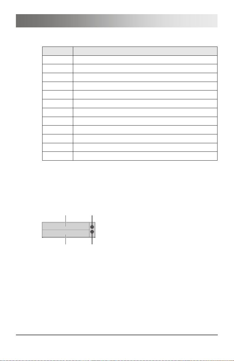
Example View – Config.txt
When using redundant CPU Units in combination with a KVM matrix, the
function of the competing control will be automatically deactivated in the
extender and will have to be performed by the KVM matrix.
Pos: 63 /806-IHSE/Technische Daten/UEB_Technisc he Daten @ 5\mod_1278578165261 _6.doc @ 42096 @ 1 @ 1
50 2013-12-06
Page 51

Specifications
7 Specifications
Pos: 64 /806-IHSE/Technische Daten/Schnittste llen/UEB_Schnitts tellen @ 5\mod_1278578201 870_6.doc @ 42114 @ 2 @ 1
7.1 Interfaces
Pos: 65 /806-IHSE/Technische Daten/Schnittste llen/DVI-D-Dual-Li nk @ 6\mod_1306496783354_6. doc @ 51660 @ 3 @ 1
7.1.1 DVI-D Dual Link
The video interface supports the DVI-D protocol. All signals that comply to
DVI-D Dual Link norm can be transmitted. This includes monitor
resolutions up tp 2560x2048@60Hz. Data rate is limited to 330 MPixel/s.
Pos: 66 /806-IHSE/Technische Daten/Schnittste llen/DVI-I-Si ngle-Link @ 5\mod_129112730832 8_6.doc @ 44809 @ @ 1
7.1.2 DVI-I Single Link
Pos: 67 /806-IHSE/Technische Daten/Schnittste llen/USB-HID @ 5\mod_127 8578292214_6.doc @ 42150 @ 3 @ 1
7.1.3 USB-HID
The video interface supports the DVI-I protocol. All analog (VGA) or digital
(DVI) signals that comply to DVI-I Single Link norm can be transmitted.
This includes e.g. monitor resolutions such as 1920x1200@60Hz, Full HD
(1080p) or 2K HD (up to 2048x1152). Data rate is limited to 165 MPixel/s.
Our devices with USB-HID interface support a maximum of two devices
with USB-HID protocol. Each USB-HID port provides a maximum current
of 100 mA.
Keyboard
Compatible with most USB keyboards. Certain keyboards with additional
functions may require custom firmware to operate. Keyboards with an
integral USB Hub (Mac keyboards e.g.) are also supported.
Mouse
Compatible with most 2-button, 3-button and scroll mice.
2013-12-06 51
Page 52

Draco KVM Extender
Other USB-HID devices
The proprietary USB emulation also supports certain other USB-HID
devices, such as specific touch screens, graphic tablets, barcode
scanners or special keyboards. Support cannot be guaranteed, however,
for every USB-HID device.
Only two USB-HID devices are supported concurrently, such as keyboard
and mouse or keyboard and touch screen. A hub is allowed, but it does
not increase the number of HID devices allowed.
To support other USB 'non-HID' devices, such as scanners, web cams or
memory devices, choose our devices with transparent USB support.
Pos: 68 /806-IHSE/Technische Daten/Schnittste llen/PS/2 @ 9\mod_13624754 19529_6.doc @ 71291 @ 3 @ 1
7.1.4 PS/2
Our devices with PS/2 interface support the use of a PS/2 keyboard and
mouse.
Keyboard
Compatible with most PS/2 keyboards, even with various special
keyboards. Certain keyboards with additional functions can be run with
special firmware.
Mouse
Compatible with most 2-button, 3-button and scroll mice.
Pos: 69 /806-IHSE/Technische Daten/Schnittste llen/474-xx (USB 2.0 (tr ansparent)) @ 7\mod_13318 01757497_6.doc @ 58190 @ 3 @ 1
7.1.5 USB 2.0 (transparent)
KVM Extender models with transparent USB 2.0 support allow the
connection of all types of USB 2.0 devices (without restriction). USB 2.0
data transfer is supported, depending on the upgrade module, with USB
high speed (max. 480 Mbit/s) or USB Full Speed (max. 12 Mbits).
Each USB 2.0 port provides a maximum current of 500 mA (high power).
Pos: 70 /806-IHSE/Technische Daten/Schnittste llen/RJ45 (Geräteko mmunikation) @ 5\mod_127857 8339308_6.doc @ 42186 @ 3 @ 1
7.1.6 RJ45 (Interconnect)
The communication of the Cat X devices requires a 1000BASE-T
connection.
Connector wiring must comply with EIA/TIA-568-B (1000BASE-T), with
RJ45 connectors at both ends. All four cable wire pairs are used.
Pos: 71 /806-IHSE/Technische Daten/Schnittste llen/Glasfaser SFP Typ LC @ 5\mod_1278937700855_6. doc @ 43149 @ 3 @ 1
52 2013-12-06
Page 53

Specifications
7.1.7 Fiber SFP Type LC (Interconnect)
The communication of fiber devices is performed via Gigabit SFPs that
have to be connected to suitable fibers fitted with connectors type LC (see
Chapter 7.2.2, Page 59).
The correct function of the device can only be guaranteed with SFPs
provided by the manufacturer.
SFP modules can be damaged by electrostatic discharge (ESD).
Please consider ESD handling specifications.
Pos: 72 /806-IHSE/Technische Daten/Schnittste llen/Serielle Schni ttstelle @ 5\mod_12911274 44390_6.doc @ 44828 @ 3 @ 1
7.1.8 Serial Interface
The serial interface option supports a full-duplex transmission with a real
hardware handshake up to a Baud rate of 115,200 Baud.
The CON Unit is cabled as DTE (Data Terminal Equipment, like CPU
output) and can be connected directly to DCE devices (Data
Communication Equipment).
A touch screen can be connected directly to the CON Unit.
To connect to a serial printer (or any other DTE instead of DCE
device), you need a null modem cable (crossed cable) between CON
Unit and the device.
Operation of several devices:
The serial interface transmits 6 signals (3 for each direction). Normally,
4 of the 6 signals are handshake signals (in addition to RxD and TxD).
The following configurations, however, can be realized using special
adapter splitting cables:
Three single 2-wire transmissions
Two transmissions with a handshake signal
A serial mouse and a single 2-wire transmission.
In this case, choose X-ON / X-OFF software handshake for traffic control
at printer and PC.
2013-12-06 53
Page 54

Draco KVM Extender
Connection Format
Speed
Data Format
Data Transmission
DTE (Data Terminal Equipment)
Up to 115,200 Baud
Format independent
RxD (Receive Data)
TxD (Transmit Data)
Traffic Control
The following signals are transmitted
(hardware handshake):
RTS (Request To Send)
CTS (Clear To Send)
DTR (Data Terminal Ready)
DSR (Data Set Ready)
Pos: 73 /806-IHSE/Technische Daten/Schnittste llen/Serielle Schni ttstelle RS422 @ 9\mod_13 62475591209_6.doc @ 71309 @ 3 @ 1
7.1.9 Serial Interface RS422
KVM Extenders with a serial interface RS422 (D-Sub 9) support a
differential full duplex transmission up to a Baud rate of 115,200 Baud.
The CPU unit is designed as controlling device and so can be for example
connected directly to video or media servers.
The CON unit is designed as a controlled device and so can be connected
directly to remote controllers.
Connection Format
Speed
Data Format
Data Transmission
Pos: 74 /806-IHSE/Technische Daten/Schnittste llen/474-xx (Analoge Audi o-Schnittstel le) @ 7\mod_1332491046975_ 6.doc @ 58270 @ 3 @ 1
Sony Standard
Up to 115,200 Baud
Format independent
Rx + (Receive Data)
Rx – (Receive Data)
Tx + (Transmit Data)
Tx – (Transmit Data)
54 2013-12-06
Page 55

Specifications
7.1.10 Analog Audio Interface
The analog audio option supports a bidirectional stereo audio
transmission, in nearly CD quality.
The audio interface is a 'line level' interface and it is designed to transmit
the signals of a sound card (or another 'line level' device) as well as to
allow the connection of active speakers to the CON Unit.
Stereo audio can be transmitted bidirectionally at the same time.
Connection of a microphone:
Connect the microphone to the 'audio' input of the CON Unit. There are
two ways to establish this connection:
The output of the CPU Unit is connected with the microphone input of
the sound card (red). Adjust the sound card to provide an additional
amplification (20 dB).
The output of the CPU Unit is connected to the audio input of the
sound card (blue). Choose this connection if the microphone has its
own pre-amplifier.
The CON Unit can do the pre-amplification of the microphone as well.
Open the CON Unit, locate the 'MIC' jumper on the audio board and close
the pins.
Specifications Analog Audio
Transmission Format Digitized virtually CD quality audio
(16 bit, 38.4 KHz)
Signal Level
Input Impedance
Connections CPU Unit 2x 3.5 mm stereo jack plug
Connections CON Unit 2x 3.5 mm stereo jack plug
Line-Level (5 Volt Pk-Pk maximum)
47 KOhm
(audio in & audio out)
(audio in & audio out)
2013-12-06 55
Page 56

Draco KVM Extender
Specifications Analog Audio USB 2.0
Transmission Format Digitized virtually CD quality audio, 16 bit
(8, 11.025, 16, 22.05, 32, 44.1, 48 KHz)
Signal Level
Input Impedance
Connections CPU Unit
Line-Level (5 Volt Pk-Pk maximum)
20 KOhm
1x USB type B female connector
Connections CON Unit 2x 3.5 mm stereo jack plug
(audio in & audio out)
Pos: 75 /806-IHSE/Technische Daten/Schnittste llen/474-xx (Digita l Audio-Schnittste llen) @ 6\mod_130458577683 2_6.doc @ 51309 @ 3 @ 1
7.1.11 Digital Audio Interface
The digital audio option supports the unidirectional transmission of digital
audio data.
Up to three sources can be connected to the CPU Unit. The active source
is transmitted. If several sources are active, the XLR signal takes priority,
otherwise the first active signal.
The three connectors on the CON Unit all concurrently provide digital
audio.
KVM Extender with digital audio option include an inbuilt sample rate
converter that allows to provide predefined sample frequencies at the
output of the CON unit.
The user can set directly the following parameters by using a configuration
file:
Activate or deactivate sample rate converter in the Config.txt file on
the flash drive of the KVM Extender.
If the sample rate converter is activated, the following characteristics
are valid:
140 dB dynamic range and -120 dB total harmonic distortion + noise.
Set sample frequency of the sample rate converter by writing the
parameter in a new line. The following sample frequencies are
available:
– 32.0 kHz (write SRC32000 in Config.txt file of the CPU unit)
– 44.1 kHz (write SRC44100 in Config.txt file of the CPU unit)
– 48.0 kHz (write SRC48000 in Config.txt file of the CPU unit)
– 96.0 kHz (write SRC96000 in Config.txt file of the CPU unit)
56 2013-12-06
Page 57

Specifications
You can use a delay for converting the sample rate. The time is set in
milliseconds and separated from the parameter for the sample rate by
a semicolon (e.g. SRC4410;12). You can set the following delays for
the sample rates:
– 32.0 kHz: 3 - 60 ms
– 44.1 kHz: 2 - 44 ms
– 48.0 kHz: 2 - 40 ms
– 96.0 kHz: 1 - 20 ms
To deactivate the sample rate converter, write SRC_NONE in the
Config.txt file of the CPU unit.
Compatibility
Standards
Bit Depth
Sample Rate
CPU Unit (Inputs) Mini-XLR (AES/EBU; symmetrical,
CON Unit (Outputs) Mini-XLR (AES/EBU; symmetrical,
Pos: 76 /806-IHSE/Technische Daten/Verbindungs kabel/UEB_Verbindung skabel @ 5\mod_1279191 107845_6.doc @ 43870 @ 2 @ 1
AES/EBU, S/PDIF, EIAJ CP1201,
IEC 60958
Dolby Digital, DTS, PCM
24 bit
32 to 96 kHz
lockable)
Coaxial (S/PDIF; RCA, Cinch)
Optical (S/PDIF; TOSLINK)
lockable)
Coaxial (S/PDIF; RCA, Cinch)
Optical (S/PDIF; TOSLINK)
2013-12-06 57
Page 58

Draco KVM Extender
7.2 Interconnect Cable
Pos: 77 /806-IHSE/Technische Daten/Verbindungs kabel/Verbindungskabe l (Cat X) @ 5\mod_12785784 06026_6.doc @ 42205 @ 3 @ 1
7.2.1 Cat X
A point-to-point connection is required. Operation with several patch fields
is possible. Routing over an active network component, such as an
Ethernet Hub, Router or Matrix, is not allowed.
Avoid routing Cat X cables along power cables.
If the site has 3-phase AC power, try to ensure that CPU Unit and
CON Unit are on the same phase.
To maintain regulatory EMC compliance, correctly installed shielded Cat X
cable must be used throughout the interconnection link.
To maintain regulatory EMC compliance, all Cat X cables need to carry
ferrites on both cable ends close to the device.
Type of Interconnect Cable
The KVM Extender requires interconnect cabling specified for Gigabit
Ethernet (1000BASE-T). The use of solid-core (AWG24), shielded, Cat 5e
(or better) is recommended.
Cat X Solid-Core Cable
AWG24
S/UTP (Cat 5e) cable according to EIA/TIA568-B. Four pairs of wires AWG24.
Connection according to EIA/TIA-568-B
(1000BASE-T).
Cat X Patch Cable
AWG26/8
S/UTP (Cat 5e) cable according to EIA/TIA568-B. Four pairs of wires AWG26/8.
Connection according to EIA/TIA-568-B
(1000BASE-T).
The use of flexible cables (patch cables) type AWG26/8 is possible,
however the maximum possible extension distance is halved.
Pos: 78 /806-IHSE/Technische Daten/Verbindungs kabel/Verbindungskabe l (Cat X)_Kabellänge 47 7-xx @ 5\mod_1278937761 105_6.doc @ 43167 @ @ 1
Maximum Acceptable Cable Length
Cat X Installation Cable
140 m (400 ft)
AWG24
Cat X Patch Cable
70 m (200 ft)
AWG26/8
Pos: 79 /806-IHSE/Technische Daten/Verbindungs kabel/Verbindungskabe l (LWL) @ 5\mod_127893796 7667_6.doc @ 43186 @ @ 1
58 2013-12-06
Page 59

Specifications
7.2.2 Fiber
A point-to-point connection is necessary. Operation with multiple patch
panels is allowed. Routing over active network components, such as
Ethernet Hubs, Switches or Routers, is not allowed.
Type of Interconnect Cable
(Cable notations according to VDE)
Type of cable Specifications
Single-mode 9μm Two fibers 9μm
I-V(ZN)H 2E9 (in-house patch cable)
I-V(ZN)HH 2E9 (in-house breakout cable)
I/AD(ZN)H 4E9 (in-house or outdoor
breakout cable, resistant)
A/DQ(ZN)B2Y 4G9 (outdoor cable, with
protection against rodents)
Multi-mode 50μm Two fibers 50μm
I-V(ZN)H 2G50 (in-house patch cable)
I/AD(ZN)H 4G50 (in-house or outdoor
breakout cable, resistant)
Multi-mode 62.5μm Two fibers 62.5μm
I-V(ZN)HH 2G62,5 (in-house breakout
cable)
A/DQ(ZN)B2Y 4G62,5 (outdoor cable,
with protection against rodents)
Maximum Acceptable Cable Length
Type of cable Maximum Acceptable Cable Length
Single-mode 9μm 10,000 m (32,800 ft)
Multi-mode 50μm (OM3) 1,000 m (3,280 ft)
Multi-mode 50μm 400 m (1,300 ft)
Multi-mode 62.5μm 200 m (650 ft)
If you use single-mode SFPs with multi-mode fibers, you normally can
double the maximum acceptable cable length.
Pos: 80 /806-IHSE/Technische Daten/Verbindungs kabel/Verbindungskabe l (LWL)_Steckver binder 477-xx @ 5\mod_12789 54447542_6.doc @ 43740 @ @ 1
Type of Connector
Pos: 81 /806-IHSE/zz_Layout/Seitenumbruch @ 8\ mod_1348581820516_0.doc @ 69462 @ @ 1
Connector
LC Connector
2013-12-06 59
Page 60

Draco KVM Extender
Pos: 82 /806-IHSE/Technische Daten/Unterstützte Per ipherie/UEB_Unter stützte Peripheri e @ 5\mod_1278578478761_6. doc @ 42242 @ 2 @ 1
7.3 Supported Peripherals
Pos: 83 /806-IHSE/Technische Daten/Unterstützte Per ipherie/USB- HID-Geräte @ 5\mod_1278578 523558_6.doc @ 42260 @ @ 1
7.3.1 USB-HID Devices
The KVM Extender will support most USB-HID devices, including the vast
majority of keyboards and mice currently on the market. Many other kinds
of HID devices such as bar-code scanners and touch screens may also be
compatible
It is not possible to guarantee support for all available USB-HID devices.
In certain cases, custom firmware may be required.
USB-HID (and other) devices that are not supported as standard will
normally operate with our devices featuring transparent USB support.
Please note that concurrent operation of more than two USB-HID devices
is not possible even if you use a USB hub.
Pos: 84 /806-IHSE/Technische Daten/Unterstützte Per ipherie/USB-2. 0-Geräte @ 5\mod_127857855 3933_6.doc @ 42278 @ @ 1
7.3.2 USB 2.0 Devices
Pos: 85 /806-IHSE/zz_Layout/Seitenumbruch @ 8\ mod_1348581820516_0.doc @ 69462 @ @ 1
KVM Extender models featuring a transparent USB 2.0 connection use
Extreme USB Technology from Icron Technologies.
This technology supports all types of USB 2.0 devices, however the
manufacturer cannot guarantee compatibility with every device on the
market. Please contact your dealer if any issues are found.
60 2013-12-06
Page 61

Specifications
7.4 Connector Pinouts
Pos: 87 /806-IHSE/Technische Daten/Pinbelegungen/ 482-xx/Buchse DMS-59 Du al-Link @ 10\mod_138 5652060067_6.doc @ 103262 @ @ 1
Connector DMS-59 Dual-Link
1-15
16-30
31-45
46-60
Pin Signal Pin Signal Pin Signal
1 GND 21 RX5_U 41 GND
2 n.c. 22 GND 42 GND
3 n.c. 23 n.c. 43 GND
4 GND 24 GND 44 BRXC_N
5 5V DVI 25 RX2_P 45 BRXC_P
6 DDC SCL 26 RX2_N 46 GND
7 DDC SDA 27 RX1_P 47 n.c.
8 GND 28 RX1_N 48 n.c.
9 BDDC SDA 29 RX0_P 49 GND
10 BDDC SCL 30 RX0_N 50 n.c.
11 B5V DVI 31 RXC_P 51 n.c.
12 GND 32 RXC_N 52 GND
13 n.c. 33 GND 53 n.c.
14 n.c. 34 GND 54 GND
15 GND 35 GND 55 n.c.
16 RX3_P 36 HPD 56 n.c.
17 RX3_N 37 n.c. 57 GND
18 RX4_P 38 n.c 58 n.c.
19 RX4_N 39 n.c. 59 n.c.
20 RX5_P 40 BHPDT 60 GND
Pos: 88 /806-IHSE/Technische Daten/Pinbelegungen/ Buchse USB Typ B @ 5\mod_127857 8750464_6.doc @ 42351 @ @ 1
2013-12-06 61
Page 62

Draco KVM Extender
Connector USB Type B
Picture Pin Signal Color
132
4
Pos: 89 /806-IHSE/Technische Daten/Pinbelegungen/ Buchse USB Typ A @ 5\mod_1278578 771214_6.doc @ 42369 @ @ 1
Pos: 90 /806-IHSE/Technische Daten/Pinbelegungen/ Buchse Mini-USB Typ B @ 5\ mod_1278578794167_6.doc @ 42387 @ @ 1
Pos: 91 /806-IHSE/Technische Daten/Pinbelegungen/ Buchse PS/2 @ 9\mod_1362476 953272_6.doc @ 71329 @ @ 1
Connector USB Type A
Picture Pin Signal Color
3
1
2 4
Connector Mini USB Type B
Picture Pin Signal Color
1
....5
Connector PS/2
1 VCC (+5VDC) Red
2 Data – White
3 Data + Green
4 GND Black
1 VCC (+5VDC) Red
2 Data – White
3 Data + Green
4 GND Black
1 VCC (+5VDC) Red
2 Data – White
3 Data + Green
4 n.c. –
5 GND Black
Picture Pin Signal
1 DATA
2 GND
3 VCC (+ 5VDC)
4 CLK
5 n.c.
6 n.c.
Pos: 92 /806-IHSE/Technische Daten/Pinbelegungen/ RJ45 @ 5\mod_12785788 20011_6.doc @ 42405 @ @ 1
62 2013-12-06
Page 63

Specifications
RJ45
Picture Pin Signal Pin Signal
1 D1+ 5 D3–
2 D1– 6 D2–
3 D2+ 7 D4+
Pos: 93 /806-IHSE/Technische Daten/Pinbelegungen/ Glasfaser SFP Typ LC @ 5\ mod_1278938501151_6.doc @ 43210 @ @ 1
Fiber SFP Typ LC
Picture Diode Signal
8..........1
4 D3+ 8 D4–
1 Data OUT
Pos: 94 /806-IHSE/Technische Daten/Pinbelegungen/ Stromversorgung @ 5\ mod_1278578849183_6. doc @ 42423 @ @ 1
Power Supply
Picture Pin Signal
Pos: 95 /806-IHSE/Technische Daten/Pinbelegungen/ D-Sub 9 (Seriell) @ 5\ mod_1291128631437_6.d oc @ 44882 @ @ 1
D-Sub 9 (Serial) RS232
Picture Pin Signal Pin Signal
Pos: 96 /806-IHSE/Technische Daten/Pinbelegungen/ D-Sub 9 (Seriell) RS422 Con trolled Device @ 9\ mod_1362477200520_6.doc @ 71349 @ @ 1
12
1.................5
6...........9
2 Data IN
Inside VCC (+5VDC)
Outside GND
1 n.c. 6 DSR
2 RxD 7 RTS
3 TxD 8 CTS
4 DTR 9 n.c.
5 GND
2013-12-06 63
Page 64

Draco KVM Extender
D-Sub 9 (Serial) RS422 Controlled Device
Picture Pin Signal Pin Signal
1.................5
6...........9
Pos: 97 /806-IHSE/Technische Daten/Pinbelegungen/ D-Sub 9 (Seriell) RS422 Con trolling Devic e @ 9\mod_1362477202220_6. doc @ 71369 @ @ 1
Pos: 98 /806-IHSE/Technische Daten/Pinbelegungen/ Stereo-Klinkenbuc hse 3,5 mm @ 5\mod_129112876515 6_6.doc @ 44901 @ @ 1
D-Sub 9 (Serial) RS422 Controlling Device
Picture Pin Signal Pin Signal
1.................5
6...........9
3.5 mm Stereo Jack Plug
1 GND 6 Rx-GND
2 RxA 7 RxB
3 TxB 8 TxA
4 Tx-GND 9 n.c.
5 n.c
1 GND 6 Tx-GND
2 TxA 7 TxB
3 RxB 8 RxA
4 Rx-GND 9 n.c.
5 n.c.
Picture Pin Signal
12 3
1 GND
2 Audio IN / OUT L
3 Audio IN / OUT R
Pos: 99 /806-IHSE/Technische Daten/Pinbelegungen/ RCA (Cinch) @ 5\mod_129112 8877593_6.doc @ 44920 @ @ 1
RCA (Cinch)
Picture Pin Signal
1 2
1 GND
2 Data IN / OUT
Pos: 100 /806-IHSE/Technische Daten/Pinbelegungen/ Mini-XLR @ 5\mod_12911 28998484_6.doc @ 44939 @ @ 1
64 2013-12-06
Page 65

Specifications
Mini-XLR
Picture Pin Signal
1 GND
2 Data +
3 Data –
1 Data IN / OUT
Pos: 101 /806-IHSE/Technische Daten/Pinbelegungen/ TOSLINK @ 5\mod_129112 9073656_6.doc @ 44958 @ @ 1
TOSLINK
132
Picture Diode Signal
1
Pos: 102 /806-IHSE/Technische Daten/Stromversorgun g/482-xx @ 10\mod_1385 652314288_6.doc @ 103285 @ 2 @ 1
7.5 Power Supply
AC Power Supply
Model Max. Current Max. Voltage Frequency
474-BODY2N 700 mA max. 100-240 V 50/60 Hz
474-BODY6R 1,400 mA max. 100-240 V 47-63 Hz
474-BODY6BP 800 mA max. 100-240 V 50/60 Hz
474-BODY21/4U 4,000 mA max. 2x 100-240 V 50/60 Hz
DC Power Supply
Model Max. Current Max. Voltage
474-BODY2/2R 3,000 mA 5 VDC
474-BODY2N 5,000 mA 5 VDC
474-BODY4/4R 5,000 mA 5 VDC
474-BODY6R 8,000 mA 5 VDC
2013-12-06 65
Page 66

Draco KVM Extender
Power Requirement
Power Requirement
(per Unit)
KVM Extender:
Max. 1,000 mA
Upgrade Modules:
Analog Audio / Serial: max. 300 mA
Serial (RS422): max. 150 mA
Digital Audio: max. 300 mA
USB-HID: max. 300 mA
PS/2: max. 650 mA
USB 2.0 embedded: max. 1,100 mA
USB 2.0: max. 2,500 mA
Pos: 103 /806-IHSE/Technische Daten/Einsatzbedin gungen/ATB_Einsa tzbedingungen @ 5\mod_1 278578980026_6.doc @ 42480 @ 2 @ 1
7.6 Environmental Conditions
Pos: 104 /806-IHSE/Technische Daten/Abmessungen/4 82-xx @ 10\mod_13856524 74888_6.doc @ 103379 @ 2 @ 1
Operating Temperature
Storage Temperature
Relative Humidity
41 to 113°F (5 to 45°C)
–13 to 140°F (–25 to 60°C)
Max. 80% non-condensing
7.7 Size
Devices in the 2-fold Vario Chassis 1
CPU Unit / CON Unit
Shipping Box
Devices in the 2-fold Vario Chassis 2
145 x 147 x 41 mm (5.7" x 5.8" x 1.7")
210 x 140 x 165 mm (8.3" x 5.5" x 6.5")
CPU Unit / CON Unit
Shipping Box
221 x 147 x 41 mm (8.7" x 5.8" x 1.7")
550 x 365 x 115 mm (21.7" x 14.4" x 4.5")
Devices in the 4-fold Vario Chassis
CPU Unit / CON Unit
Shipping Box
293 x 147 x 41 mm (11.5" x 5.8" x 1.7")
550 x 365 x 115 mm (21.7" x 14.4" x 4.5")
66 2013-12-06
Page 67

Specifications
Devices in the 6-fold Vario Chassis 6R
Pos: 105 /806-IHSE/zz_Layout/Seitenumbruch @ 8\mod_ 1348581820516_0.d oc @ 69462 @ @ 1
CPU Unit / CON Unit
Shipping Box
442 x 147 x 41 mm (17.4" x 5.8" x 1.7")
760 x 365 x 115 mm (29.9" x 14.4" x 4.5")
Devices in the 6-fold Vario Chassis 6BP
CPU Unit / CON Unit
Shipping Box
442 x 250 x 41 mm (17.4" x 9.8" x 1.7")
550 x 372 x 155 mm (21.7" x 14.6" x 6.1")
Devices in the 21-fold Vario Chassis
CPU Unit / CON Unit
Shipping Box
482 x 462 x 176 mm (19.0" x 18.2" x 6.9")
645 x 574 x 368 mm (25.4" x 22.6" x 14.5")
2013-12-06 67
Page 68

Draco KVM Extender
Pos: 106 /806-IHSE/Technische Daten/Transportge wicht /482-xx @ 10\mod_1 385652712409_6.doc @ 103403 @ 2 @ 1
7.8 Shipping Weight
Devices in the 2-fold Vario Chassis 1
CPU Unit / CON Unit
Shipping Box
0.4 kg (0.9 lb)
2.2 kg (4.9 lb)
Devices in the 2-fold Vario Chassis 2
CPU Unit / CON Unit
Shipping Box
0.8 kg (1.8 lb)
2.6 kg (5.7 lb)
Devices in the 4-fold Vario Chassis
CPU Unit / CON Unit
Shipping Box
0.9 kg (2.0 lb)
3.4 kg (7.5 lb)
Devices in the 6-fold Vario Chassis 6R
CPU Unit / CON Unit
Shipping Box
1.4 kg (3.1 lb)
4.6 kg (10.1 lb)
Devices in the 6-fold Vario Chassis 6BP
CPU Unit / CON Unit
Shipping Box
2.5 kg (5.5 lb)
3.5 kg (7.7 lb)
Devices in the 21-fold Vario Chassis
Pos: 107 /806-IHSE/Hilfe im Problemfall/UEB_Hilfe i m Problemfall @ 5\mod_12785 79113839_6.doc @ 42536 @ 1 @ 1
CPU Unit / CON Unit
Shipping Box
10.0 kg (22.1 lb)
14.5 kg (32.0 lb)
68 2013-12-06
Page 69

Troubleshooting
8 Troubleshooting
Pos: 108 /806-IHSE/Hilfe im Problemfall/Allgemein e Störung/474-xx @ 9\mod_1 373964024756_6.doc @ 77427 @ 2 @ 1
8.1 General Failures
Diagnosis Possible Reason Measure
Config.txt
parameter
without function
Pos: 109 /806-IHSE/Hilfe im Problemfall/Bildausf all/482-xx @ 10\mod_13 85652962480_6.doc @ 103427 @ 2 @ 1
Parameter not set or
saved
Start Commanc #CFG
not set
Parameter written
incorrectly
Extender not restarted Restart extender.
Write parameter into Config.txt
file and save changes.
Write start command #CFG into
first line of the Config.txt file.
Check correct spelling and
capitalization.
2013-12-06 69
Page 70

Draco KVM Extender
8.2 Blank Screen
CPU Module CON Module
3 421 21
3 42121
Rear View Rear View
Diagnosis Possible Reason Measure
LED 3 off
Power supply
Check power supply units and
the connection to the power
network.
LED 1 on or
LED 2 off
CPU Unit:
LED 3 red or
yellow
Connection between
CON Unit and CPU Unit
No video signal detected
by source (computer,
CPU)
Check interconnect cables and
connections.
Check DVI-D cable to CPU
Download DDC information from
console monitors (see
Chapter
Reboot CPU if necessary.
CON Unit:
LED 3 red or
yellow
No monitor detected
Check connection, length and
quality of the DVI-D cable to
monitor, tighten cable
thumbscrews.
No video signal detected
from CPU Unit
Check connection, length and
quality of interconnect cables
between the units.
Download DDC information from
console monitors (see
Chapter
Reboot CPU if necessary.
Pos: 110 /806-IHSE/Hilfe im Problemfall/Störung am USB-HID-Anschluss/482- xx @ 10\mod_1385653162 960_6.doc @ 103471 @ 2 @ 1
3 421 21
3 42121
6.1, Page 48).
6.1, Page 48).
70 2013-12-06
Page 71

Troubleshooting
8.3 USB-HID
CPU Module CON Module
3 421 21
3 42121
Rear View Rear View
Diagnosis Possible Reason Measure
Keyboard LEDs
Shift and Scroll
Keyboard in Command
Mode
Press <Esc> to leave Command
Mode.
are blinking
CPU Unit:
LED 3 green or
violet
No USB connection to
CPU
Check connection of USB cable
to CPU; select another USB port
if necessary.
Remove USB and power cable
and restart CPU. Connect power
cable first.
CON Unit:
LED 3 green or
violet
Problems with USB
connection
Check connection of USB cable
to USB-HID device.
Remove DVI and power cable
and restart CON Unit. Connect
power cable first.
USB device
without function
No USB-HID device Connect USB-HID device.
USB-HID device is not
Contact dealer if necessary.
supported
Pos: 111 /806-IHSE/Hilfe im Problemfall/Störung am seri ellen Anschluss/ 474-xx @ 6\mod_130458671 3332_6.doc @ 51418 @ @ 1
3 421 21
3 42121
2013-12-06 71
Page 72

Draco KVM Extender
8.4 Serial Connection
Diagnosis Possible Reason Measure
Serial device
not operational
Settings of the serial
interface
No serial connection to
CPU
No serial connection to
end device (e.g. touch
screen, keyboard)
Check Baud rate and general
settings.
Check connection via serial
cable.
Connect serial end device and
switch it on.
Check connection via serial
cable.
Touch screen
not operational
Pos: 112 /806-IHSE/Hilfe im Problemfall/Störung am An alog-Audio-Ansch luss/474-xx @ 6\mod_13045 86773051_6.doc @ 51437 @ @ 1
Hardware handshake
Adjust serial interface to X-ON /
X-OFF software handshake.
8.5 Analog Audio
Diagnosis Possible Reason Measure
CON Unit:
No signal at
audio output
CPU Unit:
No signal at
audio output
(microphone)
Pos: 113 /806-IHSE/Hilfe im Problemfall/Störung am Digi tal-Audio-Ansc hluss/474-xx @ 6\mod_1304 586853379_6.doc @ 51456 @ @ 1
No audio connection to
CPU / audio source
Connect analog audio source.
Check audio cable.
No Signal Switch analog audio source on.
Activate analog output at CPU /
audio source.
No audio connection to
audio sink
(e.g. speakers)
No audio connection to
audio source
(microphone)
Connect analog audio sink and
switch it on.
Check connection of audio cable.
Connect analog audio source
(microphone).
Check connection of audio cable.
No signal Switch analog audio source on.
Activate analog output at audio
source.
No audio connection to
audio sink (e.g. CPU)
Check connection to CPU.
Check connection of audio cable.
Check audio configuration.
72 2013-12-06
Page 73

Troubleshooting
8.6 Digital Audio
CPU Module CON Module
1
Rear View Rear View
Diagnosis Possible Reason Measure
CPU Unit:
LED 1 red
No audio connection to
CPU / audio source
Connect digital audio source.
Check connection of audio cable.
No signal Switch digital audio source on.
Activate digital output at CPU /
audio source.
CON Unit:
LED 1 red
No audio connection to
audio sink
Connect digital audio sink.
Check connection of audio cable.
(e.g. speakers)
No signal Check signal at CPU Unit.
No signal /
LEDs 1 OK
Digital Silence at active
audio source
Check LEDs at CPU Unit.
Check audio format.
Change audio input.
Pos: 114 /806-IHSE/Hilfe im Problemfall/Störung am USB-HID-Modul-Ansc hluss/474-xx @ 6\mod_1304 586906004_6.doc @ 51475 @ @ 1
1
2013-12-06 73
Page 74

Draco KVM Extender
8.7 Upgrade Module USB-HID
CPU Module CON Module
1
23
Rear View Rear View
Diagnosis Possible Reason Measure
LED 1 / 2 off Device at higher / lower
USB-HID port not
detected
Check connection of USB cable
to USB-HID device.
Connect USB-HID device.
Contact dealer if necessary.
CPU Unit:
LED 3 off
CON Unit:
LED 3 off
CON Unit:
LED 3 flashing
slowly
Pos: 115 /806-IHSE/Hilfe im Problemfall/Störung am USB-2.0-Embedded-Ansc hluss/474-xx @ 7\mod_1 331802913522_6.doc @ 58211 @ 2 @ 1
Connection between
CON Unit and CPU Unit
Keyboard in Command
Mode
Connection between
CON Unit and CPU Unit
Keyboard in Command
Mode
Check interconnect cable and
connectors.
Press <Esc> to leave Command
Mode.
Check interconnect cable and
connections.
Press <Esc> to leave Command
Mode.
1
23
74 2013-12-06
Page 75

Troubleshooting
8.8 USB 2.0 embedded
CPU Module CON Module
1
23
Rear View Rear View
Diagnosis Possible Reason Measure
CPU & CON
Unit:
LED 3 off
No connection to CPU
Check connection USB cable to
CPU; select another USB port if
necessary.
Remove USB and power cable
and restart CPU. Connect power
cable first.
CPU & CON
Unit:
No connection between
CON Unit and CPU Unit
Check interconnect cable and
connectors.
LED 2 off
CPU & CON
Unit:
LED 2 off and
USB 2.0 device
without function
No USB 2.0 device Connect USB 2.0 device.
USB 2.0 device is not
supported
Check installation at the CPU,
also the necessary drivers.
New connection of the USB 2.0
device.
Contact dealer if necessary.
Pos: 116 /806-IHSE/zz_Layout/Seitenumbruch @ 8\mod_ 1348581820516_0.d oc @ 69462 @ @ 1
1
23
2013-12-06 75
Page 76

Draco KVM Extender
Pos: 117 /806-IHSE/Hilfe im Problemfall/Störung am USB-2.0-Anschluss/4 74-xx @ 6\mod_1304586956 738_6.doc @ 51494 @ 2 @ 1
8.9 USB 2.0
CPU Module CON Module
12
3
3
12
Rear View Rear View
Diagnosis Possible Reason Measure
CPU Unit:
All LEDs off
No connection to CPU
Check connection USB cable to
CPU; select another USB port if
necessary.
Remove USB and power cable
and restart CPU. Connect power
cable first.
CON Unit:
LED 3 red
CON Unit:
LED 3 flashing
green / light
blue and
USB 2.0 device
without function
Connection between
CON Unit and CPU Unit
Check interconnect cable and
connectors.
No USB 2.0 device Connect USB 2.0 device.
USB 2.0 device is not
supported
Check installation at the CPU,
also the necessary drivers.
New connection of the USB 2.0
device.
Contact dealer if necessary.
Pos: 118 /806-IHSE/Technische Unterstützung/ATB_ Technische Unterstüt zung @ 5\mod_127857948708 9_6.doc @ 42650 @ 122 @ 1
12
12
3
3
76 2013-12-06
Page 77

Technical Support
9 Technical Support
Prior to contacting support please ensure you have read this manual, and
then installed and set-up your KVM Extender as recommended.
9.1 Support Checklist
To efficiently handle your request it is necessary to complete our checklist
for support and problem cases (Download). Keep the following information
available before you call:
Company, name, phone number and email
Type and serial number of the device (see bottom of device)
Date and number of sales receipt, name of dealer if necessary
Issue date of the existing manual
Nature, circumstances and duration of the problem
Involved components (such as graphic source/CPU, OS, graphic
card, monitor, USB-HID/USB 2.0 devices, interconnect cable)
including manufacturer and model number
Results from any testing you have done
9.2 Shipping Checklist
1. To return your device, contact your dealer to obtain a RMA number
(Return-Material-Authorization).
2. Package your devices carefully, preferably using the original box.
Add all pieces which you received originally.
3. Note your RMA number visibly on your shipment.
Devices that are sent in without a RMA number cannot be accepted. The
shipment will be sent back without being opened, postage unpaid.
Pos: 119 /806-IHSE/Zertifikate/UEB_Zertifi kate @ 5\mod_127857953493 3_6.doc @ 42668 @ 1 @ 1
2013-12-06 77
 Loading...