

Page 1

User Manual
Edition: 2013-03-12
Draco
KVM Extender
Model:
K474 Series
IHSE GmbH
Maybachstrasse 11
88094 Oberteuringen
Germany
info@ihse.de
www.ihse.de
Tel. +49 7546-9248-0
Fax +49 7546-9248-48
Page 2

Draco KVM Extender
Copyright
© 2013. All rights reserved. This information may not be reproduced in any
manner without the prior written consent of the manufacturer.
Information in this document is subject to change without notice.
Trademarks
All trademark and trade names mentioned in this document are
acknowledged to be the property of their respective owners.
Disclaimer
While every precaution has been taken during preparation of this manual,
the manufacturer assumes no liability for errors or omissions. Neither does
the manufacturer assume any liability for damages resulting from the use
of the information contained herein.
The manufacturer reserves the right to change specifications, functions, or
circuitry of the product without notice.
The manufacturer cannot accept liability for damage due to misuse of the
product or due to any other circumstances outside the manufacturer’s
control (whether environmental or installation related). The manufacturer
shall not be liable for any loss, damage, or injury arising directly, indirectly,
incidentally, or consequently from the use of this product.
2 2013-03-12
Page 3

Contents
Contents
1 About This Manual ....................................................................... 7
1.1 Scope.................................................................................. 7
1.2 Validity ................................................................................ 7
1.3 Cautions and Notes ............................................................ 7
2 Safety Instructions....................................................................... 8
3 Description ................................................................................... 9
3.1 Application .......................................................................... 9
3.2 System Overview .............................................................. 10
3.3 Product Range .................................................................. 11
3.3.1 Part Numbers ...................................................... 11
3.3.2 Chassis ............................................................... 11
3.3.3 KVM-Extender Modules ...................................... 12
3.3.4 Upgrade Modules................................................ 12
3.3.5 Complete Units ................................................... 13
3.4 Accessories Upgrade Kits ................................................. 16
3.5 Accessories....................................................................... 17
3.6 Device Views .................................................................... 18
3.6.1 2-fold Vario Chassis 474-BODY2/2R .................. 18
3.6.2 2-fold Vario Chassis 474-BODY2N ..................... 19
3.6.3 4-fold Vario Chassis 474-BODY4/4R .................. 20
3.6.4 6-fold Vario Chassis 474-BODY6R ..................... 21
3.6.5 21-fold Vario Chassis 474-BODY21R ................. 22
3.6.6 Model L- / R474-BSHC ....................................... 23
3.6.7 Model L- / R474-BSHS / -BSHX.......................... 23
3.6.8 Model L- / R474-BSHC-RED............................... 24
3.6.9 Model L- / R474-BSHS-RED............................... 24
3.6.10 Model L- / R474-BSHCV..................................... 25
3.6.11 Model L- / R474-BSHSV / -BSHXV..................... 25
3.6.12 Model L- / R474-BXH.......................................... 26
3.6.13 Model L- / R474-BXE .......................................... 26
2013-03-12 3
Page 4

Draco KVM Extender
3.6.14 Model L- / R474-BUE.......................................... 26
3.6.15 Model L- / R474-BAX .......................................... 27
3.6.16 Model L- / R474-BAP .......................................... 27
3.6.17 Model L- / R474-BXP .......................................... 28
3.6.18 Model L- / R474-BDX.......................................... 28
3.6.19 Model L- / R474-BAH.......................................... 29
3.6.20 Model L- / R474-BDH.......................................... 29
3.6.21 Model L- / R474-BAE .......................................... 30
3.6.22 Model L- / R474-BDE.......................................... 30
3.6.23 Model L- / R474-BSX .......................................... 30
3.6.24 Model L- / R474-BDD.......................................... 31
3.6.25 Modell L- / R474-BDA ......................................... 31
3.6.26 Modell L- / R474-BXTC....................................... 32
3.6.27 Modell L- / R474-BXTS ....................................... 32
3.7 Status LEDs ...................................................................... 33
3.7.1 Status KVM-Extender Module............................. 33
3.7.2 Status KVM-Extender Module VGA / DVI-I ......... 34
3.7.3 Status Upgrade Module Digital Audio ................. 35
3.7.4 Status Upgrade Module USB-HID....................... 36
3.7.5 Status Upgrade module USB 2.0 embedded ...... 37
3.7.6 Status Upgrade Module USB 2.0 ........................ 38
4 Installation .................................................................................. 39
4.1 Package Contents............................................................. 39
4.2 System Setup.................................................................... 41
4.2.1 KVM-Extender Setup .......................................... 41
4.2.2 Setup of Upgrade Modules ................................. 42
4.3 Example Applications........................................................ 43
5 Configuration.............................................................................. 45
5.1 Transmission Parameters ................................................. 45
5.2 DDC Settings .................................................................... 45
5.3 Command Mode ............................................................... 46
5.4 USB-HID Ghosting............................................................ 48
4 2013-03-12
Page 5

Contents
5.5 Configuration File.............................................................. 49
6 Operation .................................................................................... 50
6.1 Download of DDC Information .......................................... 50
7 Specifications............................................................................. 51
7.1 Interfaces .......................................................................... 51
7.1.1 DVI-D Single Link................................................ 51
7.1.2 DVI-I Single Link ................................................. 51
7.1.3 USB-HID ............................................................. 51
7.1.4 PS/2 .................................................................... 52
7.1.5 USB 2.0 (transparent) ......................................... 52
7.1.6 RJ45 (Interconnect) ............................................ 52
7.1.7 Fiber SFP Type LC (Interconnect) ...................... 53
7.1.8 Serial Interface.................................................... 53
7.1.9 Analog Audio Interface........................................ 54
7.1.10 Serial Interface RS422........................................ 55
7.1.11 Digital Audio Interface......................................... 56
7.2 Interconnect Cable............................................................ 57
7.2.1 Cat X ................................................................... 57
7.2.2 Fiber.................................................................... 59
7.3 Supported Peripherals ...................................................... 60
7.3.1 USB-HID Devices ............................................... 60
7.3.2 USB 2.0 Devices ................................................. 60
7.4 Connector Pinouts ............................................................ 61
7.5 Power Supply.................................................................... 66
7.6 Environmental Conditions ................................................. 67
7.7 Size................................................................................... 67
7.8 Shipping Weight................................................................ 68
8 Troubleshooting......................................................................... 69
8.1 Blank Screen..................................................................... 69
8.2 USB-HID ........................................................................... 70
8.3 Serial Connection.............................................................. 71
8.4 Analog Audio..................................................................... 71
2013-03-12 5
Page 6

Draco KVM Extender
8.5 Digital Audio...................................................................... 72
8.6 Upgrade Module USB-HID................................................ 73
8.7 USB 2.0 embedded........................................................... 74
8.8 USB 2.0............................................................................. 75
9 Technical Support ...................................................................... 76
9.1 Support Checklist.............................................................. 76
9.2 Shipping Checklist ............................................................ 76
10 Certificates.................................................................................. 77
10.1 CE Declaration Of Conformity........................................... 77
10.2 North American Regulatory Compliance ........................... 78
10.3 WEEE ............................................................................... 78
10.4 RoHS/RoHS 2................................................................... 78
11 Glossary...................................................................................... 79
Pos: 1 /806-IHSE/Zu diesem Handbuch/ATB_Zu diesem Handbuc h @ 5\mod_1278573163276_6. doc @ 41510 @ 1222 @ 1
6 2013-03-12
Page 7

About This Manual
1 About This Manual
1.1 Scope
This manual describes how to install your KVM Extender, how to operate it
and how to perform trouble shooting.
1.2 Validity
This manual is valid for all devices listed on the front page. The product
code is printed on the base of the devices.
1.3 Cautions and Notes
The following symbols are used in this manual:
This symbol indicates an important operating instruction that should be
followed to avoid any potential damage to hardware or property, loss of
data, or personal injury.
This symbol indicates important information to help you make the best use
of this product.
This symbol indicates best practice information to show recommended
and optimal ways to use this product in an efficient way.
Pos: 2 /806-IHSE/Sicherheitshinweise/ATB_Sic herheitshinweise @ 5\m od_1278573321245_6. doc @ 41528 @ 1 @ 1
2013-03-12 7
Page 8

Draco KVM Extender
2 Safety Instructions
To ensure reliable and safe long-term operation of your KVM Extender
please note the following guidelines:
Installation
Only use in dry, indoor environments.
The KVM Extender and the power supply units can get warm. Do not
situate them in an enclosed space without any airflow.
Do not place the power supply directly on top of the device.
Do not obscure ventilation holes.
Only use power supplies originally supplied with the product or
manufacturer-approved replacements. Do not use a power supply if it
appears to be defective or has a damaged chassis.
Connect all power supplies to grounded outlets. In each case, ensure
that the ground connection is maintained from the outlet socket
through to the power supply's AC power input.
Do not connect the link interface to any other equipment, particularly
network or telecommunications equipment.
Take any required ESD precautions.
In order to disconnect the device completely from the electric circuit, all
power cables have to be removed.
Repair
Do not attempt to open or repair a power supply unit.
Do not attempt to open or repair the KVM Extender. There are no
user serviceable parts inside.
Please contact your dealer or manufacturer if there is a fault.
Pos: 3 /806-IHSE/Beschreibung/UEB_Beschreibung @ 5\ mod_1278573379151_6. doc @ 41546 @ 1 @ 1
8 2013-03-12
Page 9

Description
3 Description
Pos: 4 /806-IHSE/Beschreibung/Verwendungszweck/ 474-xx @ 6\mod_1304579 672848_6.doc @ 50785 @ @ 1
3.1 Application
The KVM Extender is used to increase the distance between a source
(computer, CPU) and its console (keyboard, mouse, and other peripheral
devices).
The KVM Extender is designed for use with Cat X (Twisted Pair)
interconnect cables or fiber interconnect cables.
The KVM Extender with Cat X interconnect cables is unsuitable for
connection between buildings where a fiber optic based product should be
used instead.
The KVM Extender with fiber interconnect cables can also be used with
applications in environments which are difficult in electromagnetical
aspects. Electromagnetical interference can limit the maximum distance
und reliability.
Pos: 5 /806-IHSE/Beschreibung/System-Übersic ht /474-xx @ 6\mod_1304579 735410_6.doc @ 50803 @ @ 1
2013-03-12 9
Page 10
Draco KVM Extender
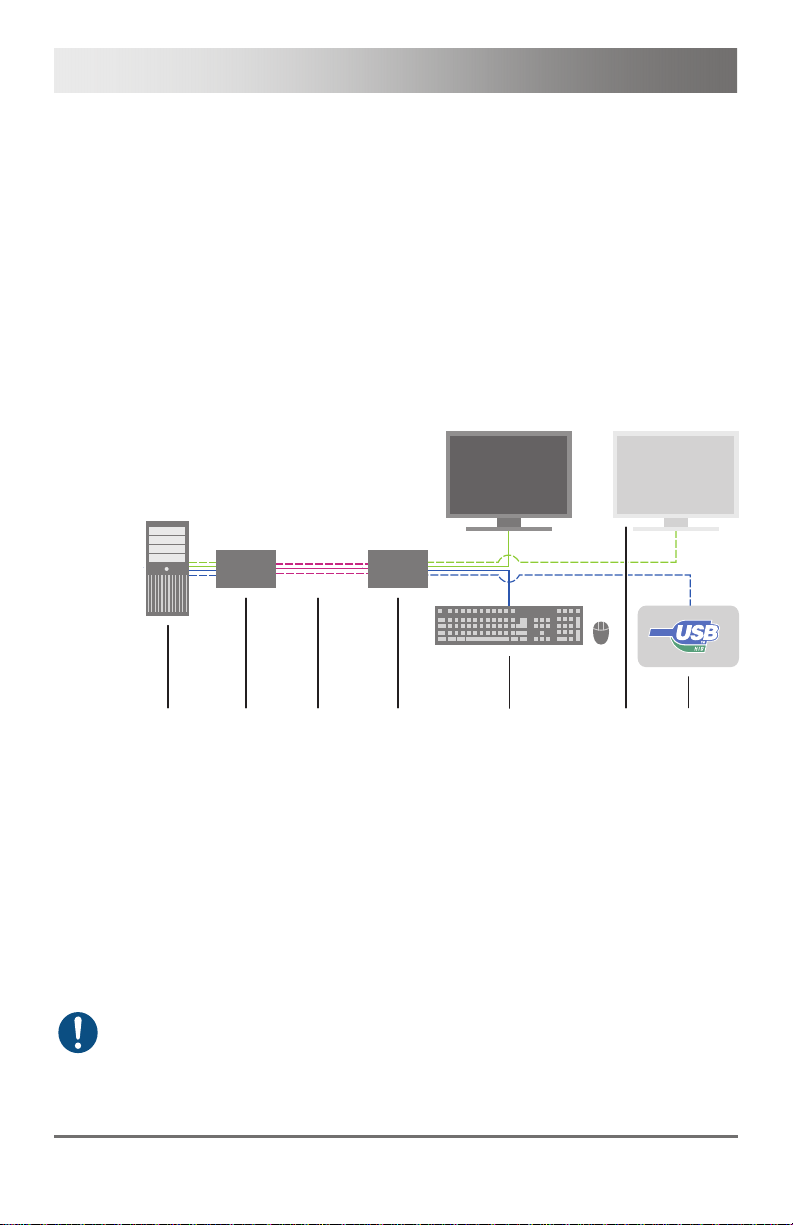
3.2 System Overview
The KVM Extender consists of at least one CPU module and one
CON module. The various modules are summarized respectively in a
vario chassis (2-fold, 4-fold or 6-fold) at CPU site and CON site (CPU and
CON unit).
The CPU module is connected directly to the source (computer, CPU)
using the supplied cables.
The CON module is connected to the console (monitor, keyboard and
mouse).
The CPU Unit and the CON modules communicate with each other
through the interconnect cables.
1
2
3
4
5
6
7
System Overview
1 Source (computer, CPU)
2 KVM Extender CPU Unit
3 Interconnect cable
4 KVM Extender CON Unit
5 Console (monitor, keyboard, mouse)
6 Second monitor (option, only with Dual-Head devices)
7 USB-HID devices (option, only with 4x USB-HID devices)
See Chapter 4.3, Page 43 for installation examples.
Pos: 6 /806-IHSE/Beschreibung/Gerätetypen/474- xx @ 6\mod_130457989777 0_6.doc @ 50821 @ 2333333 @ 1
10 2013-03-12
Page 11
Description
3.3 Product Range
3.3.1 Part Numbers
Part numbers for Connections via Cat X or Fiber Cable
All mentioned devices are available in the following versions:
Connection via Cat X cable (x = "C")
Connection via Single-mode fiber cable (x = "S")
High speed connection (3.125 Gbit/s) via Single-mode fiber cable
(x = "X")
Fiber devices can be used with Multi-mode and Single-mode cables (see
Chapter 7.2.2, Page 59).
Part numbers for CPU Unit and CON Unit
The part numbers for the CPU Unit and the CON Unit can be derived from
the part number of the complete device.
CPU Unit: L474
CON Unit: R474
All devices of the K474 series are technically compatible to the devices of
the K477 series.
3.3.2 Chassis
Model Description
474-BODY2
474-BODY2R
474-BODY2N
474-BODY4
474-BODY4R
Empty chassis for up to 2 boards, 1x external power
supply unit
Empty chassis for up to 2 boards, 1x external power
supply unit, preparation for redundancy for a second
power supply unit (external)
Empty chassis for up to 2 boards, 1x internal power
supply unit, preparation for redundancy for a second
power supply unit (external)
Empty chassis for up to 4 boards, 1x external power
supply unit
Empty chassis for up to 4 boards, 1x external power
supply unit, preparation for redundancy for a second
power supply unit (external)
2013-03-12 11
Page 12

Draco KVM Extender
Model Description
474-BODY6R
474BODY21R
Empty chassis for up to 6 boards, 1x internal power
supply unit, preparation for redundancy for a second
power supply unit (external)
Empty chassis for up to 21 boards, 1x internal power
supply unit, preparation for redundancy for a second
power supply unit (internal)
3.3.3 KVM Extender Modules
Model Description
L474-BSHx
R474-BSHx
L474-BSHxR
R474-BSHxR
L474-BSHxV
R474-BSHxV
Single-Head module for 1x DVI-D Single Link
(up to 1920x1200) with 2x USB-HID
Single-Head module for 1x DVI-D Single Link
(up to 1920x1200) with 2x USB-HID and redundant
connector for interconnect cables
Single-Head module for 1x DVI-I (VGA / DVI) Single
Link (up to 1920x1200) with 2x USB-HID
3.3.4 Upgrade Modules
Model Description
L474-BXH
R474-BXH
L474-BXE
R474-BXE
L474-BAX
R474-BAX
L474-BAP
R474-BAP
L474-BSX
R474-BSX
L474-BXP
R474-BXP
L474-BDX
R474-BDX
Upgrade module with 2x USB-HID
Upgrade module with 2x USB 2.0
Upgrade module with Analog Audio / Serial
(bidirectional)
Upgrade module with Analog Audio / Serial
(bidirectional) and PS/2
Upgrade module with serial connector (RS422)
Upgrade module with PS/2 (only available with upgrade
module Analog Audio / Serial)
Upgrade module with Digital Audio (unidirectional)
12 2013-03-12
Page 13

Description
Model Description
L474-BAH
R474-BAH
L474-BUE
R474-BUE
L474-BAE
R474-BAE
L474-BDH
R474-BDH
L474-BDE
R474-BDE
L474-BDD
R474-BDD
L474-BDA
R474-BDA
L474-BXTx
R474-BXTx
Upgrade module with Analog Audio / Serial
(bidirectional) and 2x USB-HID
Upgrade module with Analog Audio (bidirectional) and
2x USB 2.0
Upgrade module with Analog Audio / Serial
(bidirectional) and 2x USB 2.0
Upgrade module with Digital Audio (unidirectional) and
2x USB-HID
Upgrade module with Digital Audio (unidirectional) and
2x USB 2.0
Upgrade module with Digital Audio (bidirectional)
Upgrade module with Digital Audio (unidirectional) and
Analog Audio / Serial (bidirectional)
USB 2.0 upgrade module with 4x USB 2.0
3.3.5 Complete Units
Model Description
K474-1SHx
K474-1SHxRED
K474-1SEx
K474-1SHxV
K474-1SHxA
K474-1SExA
Single-Head-KVM Extender for 1x DVI-D Single Link (up
to 1920x1200), 2x USB-HID
Single-Head-KVM Extender for 1x DVI-D Single Link (up
to 1920x1200), 2x USB-HID, redundant connector for
interconnect cable
Single-Head-KVM Extender for 1x DVi-D Single Link (up
to 1920x1200) with 2x USB-HID and 2x USB 2.0
Single-Head-KVM Extender for 1x DVI-I (VGA / DVI)
Single Link (up to 1920x1200), 2x USB-HID
Single-Head-KVM Extender for 1x DVI-D Single Link (up
to 1920x1200), 2x USB-HID and Analog Audio / Serial
option
Single-Head-KVM Extender for 1x DVI-D Single Link (up
to 1920x1200) with 2x USB-HID, 2x USB 2.0 and
Analog Audio / Serial option
2013-03-12 13
Page 14

Draco KVM Extender
Model Description
K474-1SHxD
K474-1SExD
K474-1S4x
K474-1S4xA
K474-1S4xD
K474-1STx
K474-1STxA
K474-1STxD
K474-2S4x
K474-2SEx
K474-2S4xA
K474-2SExA
K474-2S4xD
K474-2SExD
K474-2STx
Single-Head-KVM Extender for 1x DVI-D Single Link (up
to 1920x1200), 2x USB-HID and Digital Audio Option
Single-Head-KVM Extender for 1x DVI-D Single Link (up
to 1920x1200) with 2x USB-HID, 2x USB 2.0 and Digital
Audio option
Single-Head-KVM Extender for 1x DVI-D Single Link (up
to 1920x1200), 4x USB-HID
Single-Head-KVM Extender for 1x DVI-D Single Link (up
to 1920x1200), 4x USB-HID and Analog Audio / Serial
option
Single-Head-KVM Extender for 1x DVI-D Single Link (up
to 1920x1200), 4x USB-HID and Digital Audio option
Single-Head-KVM Extender for 1x DVI-D Single Link (up
to 1920x1200), 2x USB-HID and 4x USB 2.0
Single-Head-KVM Extender for 1x DVI-D Single Link (up
to 1920x1200), 2x USB-HID, Analog Audio / Serial
option and 4x USB 2.0
Single-Head-KVM Extender for 1x DVI-D Single Link (up
to 1920x1200), 2x USB-HID, Digital Audio option and 4x
USB 2.0
Dual-Head-KVM Extender for 2x DVI-D Single Link
(up to 1920x1200), 4x USB-HID
Dual-Head-KVM Extender for 2x DVI-D Single Link (up
to 1920x1200) with 4x USB-HID and 2x USB 2.0
Dual-Head-KVM Extender for 2x DVI-D Single Link
(up to 1920x1200), 4x USB-HID and Analog Audio /
Serial option
Dual-Head-KVM Extender for 2x DVI-D Single Link
(up to 1920x1200) with 4x USB-HID, 2x USB 2.0 and
Analog Audio / Serial option
Dual-Head-KVM Extender for 2x DVI-D Single Link
(up to 1920x1200), 4x USB-HID and Digital Audio option
Dual-Head-KVM Extender for 2x DVI-D Single Link
(up to 1920x1200) with 4x USB-HID, 2x USB 2.0 and
Digital Audio option
Dual-Head-KVM Extender for 2x DVI-D Single Link
(up to 1920x1200), 4x USB-HID and 4x USB 2.0
14 2013-03-12
Page 15

Description
Model Description
K474-2STxA
K474-2STxD
K474-4S8x
K474-4SEx
K474-4S8xA
K474-4SExA
K474-4S8xD
K474-4SExD
K474-4STx
K474-4STxA
K474-4STxD
Devices for free configuration
Dual-Head-KVM Extender for 2x DVI-D Single Link
(up to 1920x1200), 4x USB-HID, Analog Audio / Serial
option and 4x USB 2.0
Dual-Head-KVM Extender for 2x DVI-D Single Link
(up to 1920x1200), 4x USB-HID, Digital Audio option
and 4x USB 2.0
Quad-Head-KVM Extender for 4x DVI-D Single Link
(up to 1920x1200), 8x USB-HID
Quad-Head-KVM Extender for 4x DVI-D Single Link
(up to 1920x1200) with 8x USB-HID and 2x USB 2.0
Quad-Head-KVM Extender for 4x DVI-D Single Link
(up to 1920x1200), 8x USB-HID and Analog Audio /
Serial option
Quad-Head-KVM Extender for 4x DVI-D Single Link
(up to 1920x1200) with 8x USB-HID, 2x USB 2.0 and
Analog Audio / Serial option
Quad-Head-KVM Extender for 4x DVI-D Single Link
(up to 1920x1200), 8x USB-HID and Digital Audio option
Quad-Head-KVM Extender for 4x DVI-D Single Link
(up to 1920x1200) with 8x USB-HID, 2x USB 2.0 and
Digital Audio option
Quad-Head-KVM Extender for 4x DVI-D Single Link
(up to 1920x1200), 8x USB-HID and 4x USB 2.0
Quad-Head-KVM Extender for 4x DVI-D Single Link
(up to 1920x1200), 8x USB-HID, Analog Audio / Serial
option and 4x USB 2.0
Quad-Head-KVM Extender for 4x DVI-D Single Link
(up to 1920x1200), 8x USB-HID, Digital Audio option
and 4x USB 2.0
Model Description
DRACO
VARIO 2
DRACO
VARIO 2R
Draco extender for free configuration in a 2-slot vario
chassis, external power supply unit
Draco extender for free configuration in a 2-slot vario
chassis, external power supply unit, preparation for
redundancy for a second external power supply unit
2013-03-12 15
Page 16

Draco KVM Extender
Model Description
DRACO
VARIO 2N
Draco extender for free configuration in a 2-slot vario
chassis, internal power supply unit, preparation for
redundancy of an external power supply unit
DRACO
VARIO 4
DRACO
VARIO 4R
Draco extender for free configuration in a 4-slot vario
chassis, external power supply unit
Draco extender for free configuration in a 4-slot vario
chassis, external power supply unit, preparation for
redundancy of a second external power supply unit
DRACO
VARIO 6R
Draco extender for free configuration in a 6-slot vario
chassis, internal power supply unit, preparation for
redundancy of an external power supply unit
DRACO
VARIO 21R
Draco extender for free configuration in a 21-slot vario
chassis, internal power supply unit, preparation for
redundancy for a second external power supply unit
When using redundant power supply units, there will be a load sharing.
Pos: 7 /806-IHSE/Beschreibung/Einbauoptionen/ 474-xx @ 6\mod_13045800 08551_6.doc @ 50839 @ 2 @ 1
3.4 Accessories Upgrade Kits
Model Description
474-2RMK 19"/1U rack mount kit for 2-fold chassis
474-
2NRMK
474-4RMK 19"/1U rack mount kit for 4-fold chassis
474-6RMK 19"/1U rack mount kit for 6-fold chassis
474-
VPLATE
474-
OPTRED
474-PSU2 Power supply for 2-fold chassis (spare or redundancy)
474-PSU4 Power supply for 4-fold chassis (spare or redundancy)
474-PSU6 Power supply for 6-fold chassis (spare or redundancy)
474-PSU21 Power supply for 6-fold-chassis (spare or redundancy)
474-BLND1 Blind plate 3U/4HP for 2-, 4- and 6-fold chassis
474-BLND2 Blind plate 3U/8HP for 2-, 4- and 6-fold chassis
19"/1U rack mount kit for 2-fold chassis with internal PSU
Fastening strips for screw or snap on for 2-, 4- and 6-fold
chassis
Retrofitting for redundant power supply option (without
power supply) for 2- and 4-fold chassis
16 2013-03-12
Page 17

Description
The KVM Extenders and the provided power supply units can get warm,
for this reason an installation in closed rooms without air circulation is not
allowed. Please note that you will need at least 0.5 U (height unit) for the
ventilation above the extenders, if you mount them into racks.
Pos: 8 /806-IHSE/Beschreibung/Zubehör/477-xx_C OMP @ 5\mod_1291120662750_ 6.doc @ 44582 @ 2 @ 1
3.5 Accessories
Model Description
026-2A Serial cable 1.8 m (RS232)
247-U1 USB cable 1.8 m (Type A to B)
260-5G International power supply unit 100...240VAC / 5VDC / 3 A
260-5U International power supply unit 100...240VAC / 5VDC / 4 A
436-AA VGA cable 1.8 m (VGA to DVI-I)
436-ID DVI-D cable 1.8 m (DVI-D)
445-2H DVI-D splitter cable
455-CK Stereo jack cable 1.6 m (3.5 mm Stereo)
455-CR RCA cable 2.5 m (Cinch male connector)
455-CT TOSLINK cable 1.8 m (F05 male connector)
455-CX Mini-XLR cable 1.8 m (3 pole)
Pos: 9 /806-IHSE/Beschreibung/Geräteansichten/ UEB_Geräteansic hten @ 5\mod_12785737378 08_6.doc @ 41654 @ 2 @ 1
2013-03-12 17
Page 18

Draco KVM Extender
3.6 Device Views
Pos: 10 /806-IHSE/Beschreibung/Geräteansichte n/474-xx/2-fac h Vario-Gehäuse 474-BODY2/ 2R @ 6\mod_130458028056 6_6.doc @ 50858 @ 3 @ 1
3.6.1 2-fold Vario Chassis 474-BODY2/2R
CPU and CON Unit
Rear View
1 Slot for modules #1
2 Connect to 5VDC power supply (standard)
3 Slot for modules #2
4 Connect to 5VDC power supply (redundancy, optional)
Pos: 11 /806-IHSE/Beschreibung/Geräteansichte n/474-xx/2-fac h Vario-Gehäuse 474-BODY2 N @ 8\mod_1348578478411_6. doc @ 69380 @ 3 @ 1
3
1
4
2
18 2013-03-12
Page 19

Description
3.6.2 2-fold Vario Chassis 474-BODY2N
CPU and CON Unit
3
4
Pos: 12 /806-IHSE/zz_Layout/Seitenumbruch @ 8\ mod_1348581820516_0.doc @ 69462 @ @ 1
1
2
Rear View
1 Slot for modules #1
2 Connect to power supply (standard)
3 Slot for modules #2
4 Connect to 5VDC power supply (redundancy)
The 2-fold vario chassis with an internal power supply is not equipped with
a fuse on primary side. Therefore the protection against excessive
currents has to be provided by the electrical installation of the building.
2013-03-12 19
Page 20

Draco KVM Extender
Pos: 13 /806-IHSE/Beschreibung/Geräteansichte n/474-xx/4-fac h Vario-Gehäuse 474-BODY4/ 4R @ 6\mod_130458035909 8_6.doc @ 50876 @ 3 @ 1
3.6.3 4-fold Vario Chassis 474-BODY4/4R
CPU and CON Unit
Pos: 14 /806-IHSE/zz_Layout/Seitenumbruch @ 8\ mod_1348581820516_0.doc @ 69462 @ @ 1
4
1
5
2
6
3
Rear View
1 Slot for modules #3
2 Slot for modules #1
3 Connect to 5VDC power supply (standard)
4 Slot for modules #4
5 Slot for modules #2
6 Connect to 5VDC power supply (redundancy, optional)
For operation with three KVM Extender CON modules and a USB 2.0
CON module in a 4-fold vario chassis, an external power supply unit at the
second 5VDC connector is explicitly necessary. In this case, redundancy
is inapplicable.
20 2013-03-12
Page 21

Description
Pos: 15 /806-IHSE/Beschreibung/Geräteansichte n/474-xx/6-fac h Vario-Gehäuse 474-BODY6 R @ 6\mod_1304580442488_6. doc @ 50894 @ 3 @ 1
3.6.4 6-fold Vario Chassis 474-BODY6R
CPU and CON Unit
Pos: 16 /806-IHSE/zz_Layout/Seitenumbruch @ 8\ mod_1348581820516_0.doc @ 69462 @ @ 1
6
1
7
2
8
3
5
4
Rear View
1 Slot for modules #5
2 Slot for modules #3
3 Slot for modules #1
4 Connect to power supply (standard)
5 Connect to 5VDC power supply (standard)
6 Slot for modules #6
7 Slot for modules #4
8 Slot for modules #2
For operation with KVM Extender modules in a 6-fold vario chassis, an
external power supply unit at the 5VDC connector is explicitly necessary.
In this case, redundancy is inapplicable.
The 6-fold vario chassis is not equipped with a fuse on primary side.
Therefore the protection against excessive currents has to be provided by
the electrical installation of the building.
2013-03-12 21
Page 22

Draco KVM Extender
Pos: 17 /806-IHSE/Beschreibung/Geräteansichte n/474-xx/21-fac h Vario-Gehäuse 474-BODY 21R @ 8\mod_1348579151346_ 6.doc @ 69400 @ @ 1
3.6.5 21-fold Vario Chassis 474-BODY21R
CPU and CON Unit
Pos: 18 /806-IHSE/zz_Layout/Seitenumbruch @ 8\ mod_1348581820516_0.doc @ 69462 @ @ 1
1
Front View
1 Slots for modules #1 - #21
2
1
Rear View
1 Connect to power supply 2
2 Locking for power supply 2 (redundancy)
3 Locking for power supply 1 (standard)
4 Connect to power supply 1
3
4
22 2013-03-12
Page 23

Description
Pos: 19 /806-IHSE/Beschreibung/Geräteansichte n/474-xx/Typ L- / R474-BSHC @ 6\mod_13045804794 41_6.doc @ 50912 @ 3 @ 1
3.6.6 Model L- / R474-BSHC
CPU Module CON Module
12
3
4
Rear View Rear View
1 Service port
2 Connect to interconnect cable
3 To CPU: USB-HID
4 To CPU: DVI-D
Pos: 20 /806-IHSE/Beschreibung/Geräteansichte n/474-xx/Typ L- / R474-BSHS / -BSHX @ 6\mod_13045805 36098_6.doc @ 50930 @ 3 @ 1
1 Service port
2 Connect to interconnect cable
3 Connect to USB-HID devices
4 Connect to DVI monitor
3.6.7 Model L- / R474-BSHS / -BSHX
CPU Module CON Module
3
4
1 Service port
2 Connect to interconnect cable
3 Connect to USB-HID devices
4 Connect to DVI monitor
Pos: 21 /806-IHSE/zz_Layout/Seitenumbruch @ 8\ mod_1348581820516_0.doc @ 69462 @ @ 1
12
Rear View Rear View
1 Service port
2 Connect to interconnect cable
3 To CPU: USB-HID
4 To CPU: DVI-D
12
12
3
3
4
4
2013-03-12 23
Page 24

Draco KVM Extender
Pos: 22 /806-IHSE/Beschreibung/Geräteansichte n/474-xx/Typ L- / R474-BSHC-RED @ 9\mod_13624719 88604_6.doc @ 71210 @ 3 @ 4
3.6.8 Model L- / R474-BSHCR
CPU Module CON Module
4
3
2
15
Rear View Rear View
1 Service port
2 Connect to interconnect cable 1
3 Connect to interconnect cable 2
4 To CPU: USB-HID
5 To CPU: DVI-D
Pos: 23 /806-IHSE/Beschreibung/Geräteansichte n/474-xx/Typ L- / R474-BSHS-RED @ 9\mod_13624719 95312_6.doc @ 71230 @ 3 @ 4
3.6.9 Model L- / R474-BSHSR
CPU Module CON Module
4
3
2
15
Rear View Rear View
1 Service port
2 Connect to interconnect cable 1
3 Connect to interconnect cable 2
4 To CPU: USB-HID
5 To CPU: DVI-D
Pos: 24 /806-IHSE/Beschreibung/Geräteansichte n/474-xx/Typ L- / R474-BSHCV @ 6\mod_13045834209 10_6.doc @ 50948 @ 3 @ 1
15432
1 Service port
2 Connect to interconnect cable 1
3 Connect to interconnect cable 2
4 Connect to USB-HID devices
5 Connect to DVI monitor
4
3
2
15
1 Service port
2 Connect to interconnect cable 1
3 Connect to interconnect cable 2
4 Connect to USB-HID devices
5 Connect to DVI monitor
24 2013-03-12
Page 25

Description
3.6.10 Model L- / R474-BSHCV
CPU Module CON Module
4
56
123
12
Rear View Rear View
1 Service port (KVM)
2 Connect to interconnect cable
3 To CPU: USB-HID
4 To CPU: DVI-I (VGA / DVI)
5 IR receiver for remote control
1 Service port
2 Connect to interconnect cable
3 Connect to USB-HID devices
4 IR receiver for remote control
5 Connect to DVI monitor
6 Service port (DVI-I)
Pos: 25 /806-IHSE/Beschreibung/Geräteansichte n/474-xx/Typ L- / R474-BSHSV / -BSHXV @ 6\mod_1304583 459332_6.doc @ 50966 @ 3 @ 1
3.6.11 Model L- / R474-BSHSV / -BSHXV
CPU Module CON Module
4
5 6
Rear View Rear View
1 Service port (KVM)
2 Connect to interconnect cable
3 To CPU: USB-HID
4 To CPU: DVI-I (VGA / DVI)
5 IR receiver for remote control
6 Service port (DVI-I)
Pos: 26 /806-IHSE/Beschreibung/Geräteansichte n/474-xx/Typ L- / R474-BXH @ 6\mod_13045835076 45_6.doc @ 50984 @ 3 @ 1
123
12
1 Service port
2 Connect to interconnect cable
3 Connect to USB-HID devices
4 IR receiver for remote control
5 Connect to DVI monitor
3
3
5
4
5
4
2013-03-12 25
Page 26

Draco KVM Extender
3.6.12 Model L- / R474-BXH
CPU Module CON Module
1
Rear View Rear View
1 To CPU: USB-HID 1 Connect to USB-HID devices
Pos: 27 /806-IHSE/Beschreibung/Geräteansichten/ 474-xx/Typ L- / R474-BXE @ 7\mod_1331 798896275_6.doc @ 58110 @ 3 @ 1
3.6.13 Model L- / R474-BXE
CPU Module CON Module
1
Rear View Rear View
1 To CPU: USB 2.0 1 Connect to USB 2.0 devices
Pos: 28 /806-IHSE/Beschreibung/Geräteansichte n/474-xx/Typ L- / R474-BUE @ 7\mod_13317990387 17_6.doc @ 58130 @ 3 @ 1
3.6.14 Model L- / R474-BUE
CPU Module CON Module
1
Rear View Rear View
1 To CPU: USB 2.0 1 Audio IN
When using USB audio within a KVM matrix, instant switching is not
possible due to the deregistration and registration process of the USB.
Pos: 29 /806-IHSE/Beschreibung/Geräteansichten/ 474-xx/Typ L- / R474-BAX @ 6\mod_1304 583540285_6.doc @ 51002 @ 3 @ 1
23
1
1
1
2 Audio OUT
3 Connect to USB 2.0 devices
26 2013-03-12
Page 27

Description
3.6.15 Model L- / R474-BAX
CPU Module CON Module
1
3
2
Rear View Rear View
1 Connect to serial (D-Sub 9)
2 Audio IN
3 Audio OUT
Pos: 30 /806-IHSE/Beschreibung/Geräteansichten/ 474-xx/Typ L- / R474-BAP @ 9\mod_1362 472648439_6.doc @ 71250 @ 3 @ 4
3.6.16 Model L- / R474-BAP
CPU Module CON Module
Rear View Rear View
1 Connect to serial (D-Sub 9)
2 Audio IN
3 Audio OUT
4 To CPU: PS/2 mouse
5 To CPU: PS/2 keyboard
Pos: 31 /806-IHSE/Beschreibung/Geräteansichten/ 474-xx/Typ L- / R474-BXP @ 8\mod_1348 579797358_6.doc @ 69420 @ 3 @ 1
1
3
2
45
123
1 Connect to serial (D-Sub 9)
2 Audio IN
3 Audio OUT
123
1 Connect to serial (D-Sub 9)
2 Audio IN
3 Audio OUT
4 Connect to PS/2 mouse
5 Connect to PS/2 keyboard
45
2013-03-12 27
Page 28

Draco KVM Extender
3.6.17 Model L- / R474-BXP
CPU Module CON Module
1
234
Rear View Rear View
1 Connect to local PS/2 mouse
2 Connect to local PS/2 keyboard
3 To CPU: PS/2 mouse
4 To CPU: PS/2 keyboard
The upgrade module L- / R474-BXP is only available in combination with
the upgrade modules L- / R474-BAX and –BAH. A separate slot is
required for each module.
Pos: 32 /806-IHSE/zz_Layout/Seitenumbruch @ 8\ mod_1348581820516_0.doc @ 69462 @ @ 1
Pos: 33 /806-IHSE/Beschreibung/Geräteansichte n/474-xx/Typ L- / R474-BDX @ 6\mod_13045835778 01_6.doc @ 51020 @ 3 @ 1
3.6.18 Model L- / R474-BDX
CPU Module CON Module
Rear View Rear View
1 S/PDIF input (RCA)
2 AES/EBU input (Mini-XLR)
3 S/PDIF input (TOSLINK)
Pos: 34 /806-IHSE/Beschreibung/Geräteansichte n/474-xx/Typ L- / R474-BAH @ 6\mod_13045836117 85_6.doc @ 51038 @ 3 @ 1
1
3
2
1 Connect to PS/2 mouse
2 Connect to PS/2 keyboard
1
3
2
1 S/PDIF output (RCA)
2 AES/EBU output (Mini-XLR)
3 S/PDIF output (TOSLINK)
1
2
28 2013-03-12
Page 29

Description
3.6.19 Model L- / R474-BAH
CPU Module CON Module
1
3
2
4
Rear View Rear View
1 Connect to serial (D-Sub 9)
2 Audio IN
3 Audio OUT
4 To CPU: USB-HID
Pos: 35 /806-IHSE/Beschreibung/Geräteansichte n/474-xx/Typ L- / R474-BDH @ 6\mod_130458364645 7_6.doc @ 51056 @ 3 @ 1
3.6.20 Model L- / R474-BDH
CPU Module CON Module
Rear View Rear View
1 S/PDIF input (RCA)
2 AES/EBU input (Mini-XLR)
3 S/PDIF input (TOSLINK)
4 To CPU: USB-HID
Pos: 36 /806-IHSE/Beschreibung/Geräteansichten/ 474-xx/Typ L- / R474-BAE @ 7\mod_1331 799164939_6.doc @ 58150 @ 3 @ 1
1
3
2
4
123
4
1 Connect to serial (D-Sub 9)
2 Audio IN
3 Audio OUT
4 Connect to USB-HID devices
1
3
2
4
1 S/PDIF output (RCA)
2 AES/EBU output (Mini-XLR)
3 S/PDIF output (TOSLINK)
4 Connect to USB-HID devices
2013-03-12 29
Page 30

Draco KVM Extender
3.6.21 Model L- / R474-BAE
CPU Module CON Module
1
3
2
4
Rear View Rear View
1 Connect to serial (D-Sub 9)
2 Audio IN
3 Audio OUT
4 To CPU: USB 2.0
Pos: 37 /806-IHSE/Beschreibung/Geräteansichte n/474-xx/Typ L- / R474-BDE @ 8\mod_13485802724 66_6.doc @ 69440 @ 3 @ 1
3.6.22 Model L- / R474-BDE
CPU Module CON Module
1
3
2
4
Rear View Rear View
1 S/PDIF input (RCA)
2 AES/EBU input (Mini-XLR)
3 S/PDIF input (TOSLINK)
4 To CPU: USB 2.0
Pos: 38 /806-IHSE/Beschreibung/Geräteansichten/ 474-xx/Typ L- / R474-BSX @ 9\mod_1362 472913267_6.doc @ 71270 @ 3 @ 4
3.6.23 Model L- / R474-BSX
123
1 Connect to serial (D-Sub 9)
2 Audio IN
3 Audio OUT
4 Connect to USB 2.0 devices
1
3
2
1 S/PDIF output (RCA)
2 AES/EBU output (Mini-XLR)
3 S/PDIF output (TOSLINK)
4 Connect to USB 2.0 devices
4
4
CPU Module CON Module
1
1
Rear View Rear View
1 Connect to serial (D-Sub 9) 1 Connect to serial (D-Sub 9)
Pos: 39 /806-IHSE/zz_Layout/Seitenumbruch @ 8\ mod_1348581820516_0.doc @ 69462 @ @ 1
30 2013-03-12
Page 31

Description
Pos: 40 /806-IHSE/Beschreibung/Geräteansichte n/474-xx/Typ L- / R474-BDD @ 6\mod_130458369642 6_6.doc @ 51074 @ 3 @ 1
3.6.24 Model L- / R474-BDD
CPU Module CON Module
1
3
2
5
4
6
Rear View Rear View
1 S/PDIF input (RCA)
2 AES/EBU input (Mini-XLR)
3 S/PDIF input (TOSLINK)
4 S/PDIF output (RCA)
5 AES/EBU output (Mini-XLR)
6 S/PDIF output (TOSLINK)
Pos: 41 /806-IHSE/Beschreibung/Geräteansichte n/474-xx/Typ L- / R474-BDA @ 6\mod_13045837534 26_6.doc @ 51092 @ 3 @ 1
3.6.25 Modell L- / R474-BDA
CPU Module CON Module
Pos: 42 /806-IHSE/zz_Layout/Seitenumbruch @ 8\ mod_1348581820516_0.doc @ 69462 @ @ 1
1
Rear View Rear View
1 S/PDIF input (RCA)
2 AES/EBU input (Mini-XLR)
3 S/PDIF input (TOSLINK)
4 Connect to serial (D-Sub 9)
5 Audio IN
6 Audio OUT
3
2
5
4
1
3
2
1 S/PDIF output (RCA)
2 AES/EBU output (Mini-XLR)
3 S/PDIF output (TOSLINK)
4 S/PDIF input (RCA)
5 AES/EBU input (Mini-XLR)
6 S/PDIF input (TOSLINK)
6
1
3
2
1 S/PDIF output (RCA)
2 AES/EBU output (Mini-XLR)
3 S/PDIF output (TOSLINK)
4 Connect to serial (D-Sub 9)
5 Audio IN
6 Audio OUT
5
4
6
5
4
6
2013-03-12 31
Page 32

Draco KVM Extender
Pos: 43 /806-IHSE/Beschreibung/Geräteansichte n/474-xx/Typ L- / R474-BXTC @ 6\mod_13045837845 82_6.doc @ 51110 @ 3 @ 1
3.6.26 Modell L- / R474-BXTC
CPU Module CON Module
12
3
Rear View Rear View
1 Service port
2 Connect to interconnect cable
3 To CPU: USB 2.0
Pos: 44 /806-IHSE/Beschreibung/Geräteansichte n/474-xx/Typ L- / R474-BXTS @ 6\mod_1304583818 676_6.doc @ 51128 @ 3 @ 1
3.6.27 Modell L- / R474-BXTS
CPU Module CON Module
3
Pos: 45 /806-IHSE/zz_Layout/Seitenumbruch @ 8\ mod_1348581820516_0.doc @ 69462 @ @ 1
12
Rear View Rear View
1 Service port
2 Connect to interconnect cable
3 To CPU: USB 2.0
It is only allowed to use one USB 2.0 CON module per chassis.
12
3
4
1 Service port
2 Connect to interconnect cable
3 Connect to USB 2.0 devices
12
3
4
1 Service port
2 Connect to interconnect cable
3 Connect to USB 2.0 devices
32 2013-03-12
Page 33

Description
Pos: 46 /806-IHSE/Beschreibung/Diagnose LEDs/ UEB_Diagnose_LEDs @ 6\mod_1304 584004723_6.doc @ 51146 @ @ 1
3.7 Status LEDs
Pos: 47 /806-IHSE/Beschreibung/Diagnose LEDs/474- xx/Diagnose KVM-E xtender-Modul @ 6\mod_1304 584091941_6.doc @ 51165 @ 3 @ 1
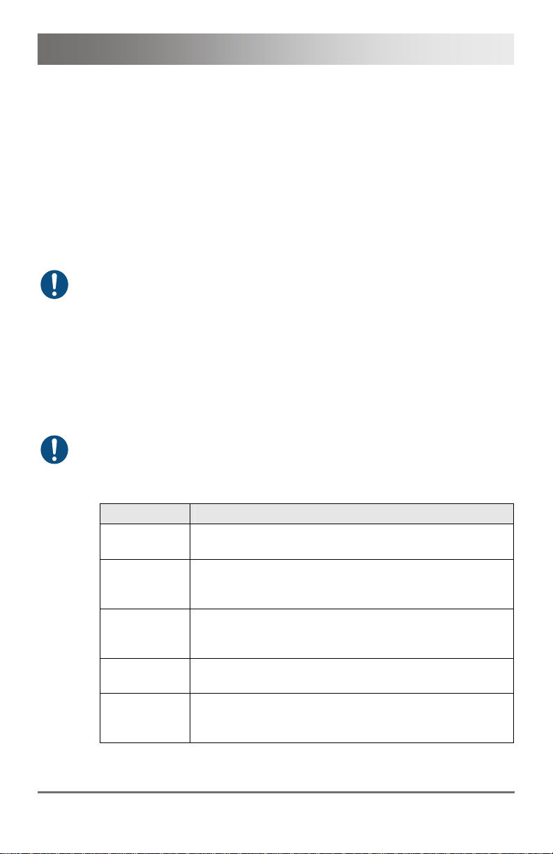
3.7.1 Status KVM Extender Module
The KVM Extender module is fitted with a multi color LED on both sides
for overall status indication and with two further LEDs on the back side for
indication of the connection status.
CPU Module CON Module
12
231
3
231
1
2
Rear View Rear View
LED 1 and 2: Connection Status
Pos. LED Status Description
Failure LED
(green)
Status LED
(green)
Off Connection available 1
On or
Flashing
Connection failure (flashing for about
20 s following a connection failure)
Flashing No connection via interconnect cable 2
On Connection available
LED 3: USB and Video Status
LED color Description
Red Device ready
Violet
Connection and USB signal (interconnect) available
Green Connection and video signal available
3
Light Blue
Pos: 48 /806-IHSE/Beschreibung/Diagnose LEDs/474- xx/Diagnose KVM-E xtender-Modul VGA / DVI- I @ 6\mod_1304584132098_6. doc @ 51183 @ 3 @ 1
Connection, USB and video signal available
(operating status)
2013-03-12 33
Page 34

Draco KVM Extender
3.7.2 Status KVM Extender Module VGA / DVI-I
The KVM Extender module with VGA / DVI-I input is fitted with a multicolor LED on the front side of the CPU Unit for indication of connection
status. Further information is available via on screen display (OSD) (see
manual for the Media / DVI Converter K238-5V (Download)).
CPU Module
Front View
LED 1: Connection Status VGA / DVI-I
LED color Description
Dark Red No video signal; monitor not detected
Red Video signal not supported; monitor not detected
Green Video signal supported; monitor not detected
Blue No video signal; monitor detected
Violet Video signal not supported; monitor detected
Light Blue Video signal supported; monitor detected
Pos: 49 /806-IHSE/Beschreibung/Diagnose LEDs/474- xx/Diagnose Zusatz modul Digital-Audio @ 6\mod_1304584173301_ 6.doc @ 51201 @ 3 @ 1
34 2013-03-12
 Loading...