

Page 1

REPEATER/CROSS- REPEATER
Welcome to the Repeater/Cross- Repeater Family!
Thank you for purchasing a Repeater/Cross- Repeater! We appreciate your business, and we
think you’ll appreciate the many ways that your Repeater/Cross- Repeater system will save
you money, time, and effort.
That’s because our Repeater/Cross- Repeater allows, to double the total allowed distance of a
DVXi KVM Extender system for remotely locating a console (DVI-monitor, keyboard and
mouse).
Wherever long distances are usual, e.g. airports, industrial plants, call- centres or in
distributed computer centres, the Repeater/Cross- Repeater is the best way, to solve all
problems in remotely locating your console. 6 different types are available: There are three
types for repeating the signals and doubling the distance and three types to extend the
distance and simultaneously convert from one medium to another (e.g. CATx to Multimode).
This manual will tell you all about your new Repeater/Cross- Repeater, including how to
install, operate, and troubleshoot it. For an introduction to the Repeater/Cross- Repeater, see
Chapter 2. The Repeater/Cross- Repeater product codes covered in this manual are:
Repeater Devices
K471-CT: CATx Repeater to double the distance to up to 280m
K471-MM: Multimode Repeater double the distance to up to 800m
K471-SS: Singlemode Repeater double the distance to up to 20km
Cross- Repeater Devices
K471-CM: CATx/Multimode Cross Repeater; distance CATx up to 140m, Multimode
K471-DM: CATx/Multimode Dual Cross Repeater; distance CATx up to 140m,
K471-CS: CATx/Singlemode Cross Repeater; distance CATx up to 140m,
K471-DS: CATx/Singlemode Dual Cross Repeater; distance CATx up to 140m,
K471-MS: Multimode/Singlemode Cross Repeater; distance Multimode up to 400m,
up to 400m
Multimode up to 400m
Singlemode up to 10.000m
Singlemode up to 10.000m
Singlemode up to 10km
Rev. : 09/25/2012
1
Page 2
REPEATER/CROSS- REPEATER
Copyrights and Trademarks
©2009. All rights reserved. This information may not be reproduced in any manner without
the prior written consent of the manufacturer.
Information in this document is subject to change without notice and the manufacturer shall
not be liable for any direct, indirect, special, incidental or consequential damages in
connection with the use of this material.
All trademark and trade names mentioned in this document are acknowledged to be the
property of their respective owners.
Disclaimer
While every precaution has been taken in the preparation of this manual, the manufacturer
assumes no responsibility for errors or omissions. Neither does the manufacturer assume any
liability for damages resulting from the use of the information contained herein. The
manufacturer reserves the right to change the specifications, functions, or circuitry of the
product without notice.
The manufacturer cannot accept liability for damage due to misuse of the product or due to
any other circumstances outside the manufacturer’s control (whether environmental or
installation related). The manufacturer shall not be responsible for any loss, damage, or injury
arising directly, indirectly, or consequently from the use of this product.
Cautions and Notes
The following symbols are used in this guide:
CAUTION: This indicates an important operating instruction
that should be followed to avoid any potential damage to
hardware or property, loss of data, or personal injury.
NOTE. This indicates important information to help you make the best use of
this product.
2
Rev. : 09/25/2012
Page 3

EMPTY PAGE
.
Rev. : 09/25/2012
3
Page 4

REPEATER/CROSS- REPEATER
EC DECLARATION OF CONFORMITY
The products listed below in the form as delivered are in conformity with the provisions
of the following European Directives:
2004/108/EG Council Directive on the approximation of the laws of the Member States
relating to electromagnetic compatibility
CE-marking 2009
Product list:
K471-CT, K471-MM, K471-SS
K471-CM, K471-DM, K471-CS, K471-DS, K471-MS
Conformity to the Directives is assured through the application of the following
standards:
EN 55022: 09/2006 Class A
IEC 61000-4-2: 02/2001
IEC 61000-4-3: 05/2006
IEC 61000-4-4: 12/2004
IEC 61000-4-5: 11/2006
This declaration certifies the conformity to the specified directives but contains no
assurance of properties. The safety documentation noted in this manual shall be
considered in detail. The length of the attached CPU- or Console Cables must not exceed
3m. The use of suggested interconnect cables is mandatory.
Oberteuringen, June 23rd, 2009
The management
manufacturer: IHSE GmbH
Maybachstrasse 11
88094 Oberteuringen
Germany
WARNING: This equipment has been found to comply with the limits for a Class A digital
device, pursuant to Part 15 of the FCC Rules. These limits are designed to provide reasonable
protection against harmful interference when the equipment is operated in a commercial
environment. This equipment generates, uses, and can radiate radio frequency energy and, if
not installed and used in accordance with the instruction manual, may cause harmful
interference to radio communications. Operation of this equipment in a residential area is
likely to cause harmful interference in which case the user will be required to correct the
interference at his own expense.
4
Rev. : 09/25/2012
Page 5
SAFETY PRECAUTIONS AND INSTALLATION GUIDELINES
Safety Precautions and Installation Guidelines
To ensure reliable and safe long-term operation, please note the following installation
guidelines:
• Do not use CATx-devices to link between buildings – please use fibre devices.
• Only use in dry, indoor environments.
• If the building has 3-phase AC power, try to ensure that equipment connected to the
Local and Remote units is on the same phase.
• Try not to route a CATx link cable alongside power cables.
• The Repeater/Cross- Repeater and any power supplies can get warm. Do not locate them
in an enclosed space without any airflow.
• Do not place a power supplies directly on top of a unit.
• Do not obstruct a unit’s ventilation existing holes.
To safeguard against personal injury and avoid possible
damage to equipment or property, please observe the
following:
• Only use power supplies originally supplied with the
product or manufacturer-approved replacements. Do not
attempt to dismantle or repair any power supply. Do not
use a power supply if it appears to be defective or has a
damaged case.
• Connect all power supplies to grounded outlets. In each
case, ensure that the ground connection is maintained
from the outlet socket through to the power supply’s AC
power input.
• Do not attempt to modify or repair this product, or make
a connection from the interconnection link interface to
any other products, especially telecommunications or
network equipment.
Rev. : 09/25/2012
5
Page 6

REPEATER/CROSS- REPEATER
Contents
1. Quick Setup 7
2. Overview 8
2.1 Introduction 8
2.2 Glossary 8
2.3 Example of a Repeater/Cross- Repeater System 9
2.4 Features 10
2.5 Product Range 11
2.6 How to Use This Guide 11
3. Installation 12
3.1 Package Contents 12
3.2 Interconnection Cable Requirements 13
3.3 System Setup 14
3.4 Device Views 15
3.5 Diagnostics 16
4. Service Setup 17
4.1 Setup at the Repeater/Cross- Repeater 18
4.2 installation instruction 19
5. Troubleshooting 21
Appendix A: Example Applications 22
Appendix B: Rack Mount Options 25
Appendix D: Calling Technical Support 27
Appendix F: Specifications 28
Appendix G: Connectors 30
6
Rev. : 09/25/2012
Page 7
QUICK SETUP
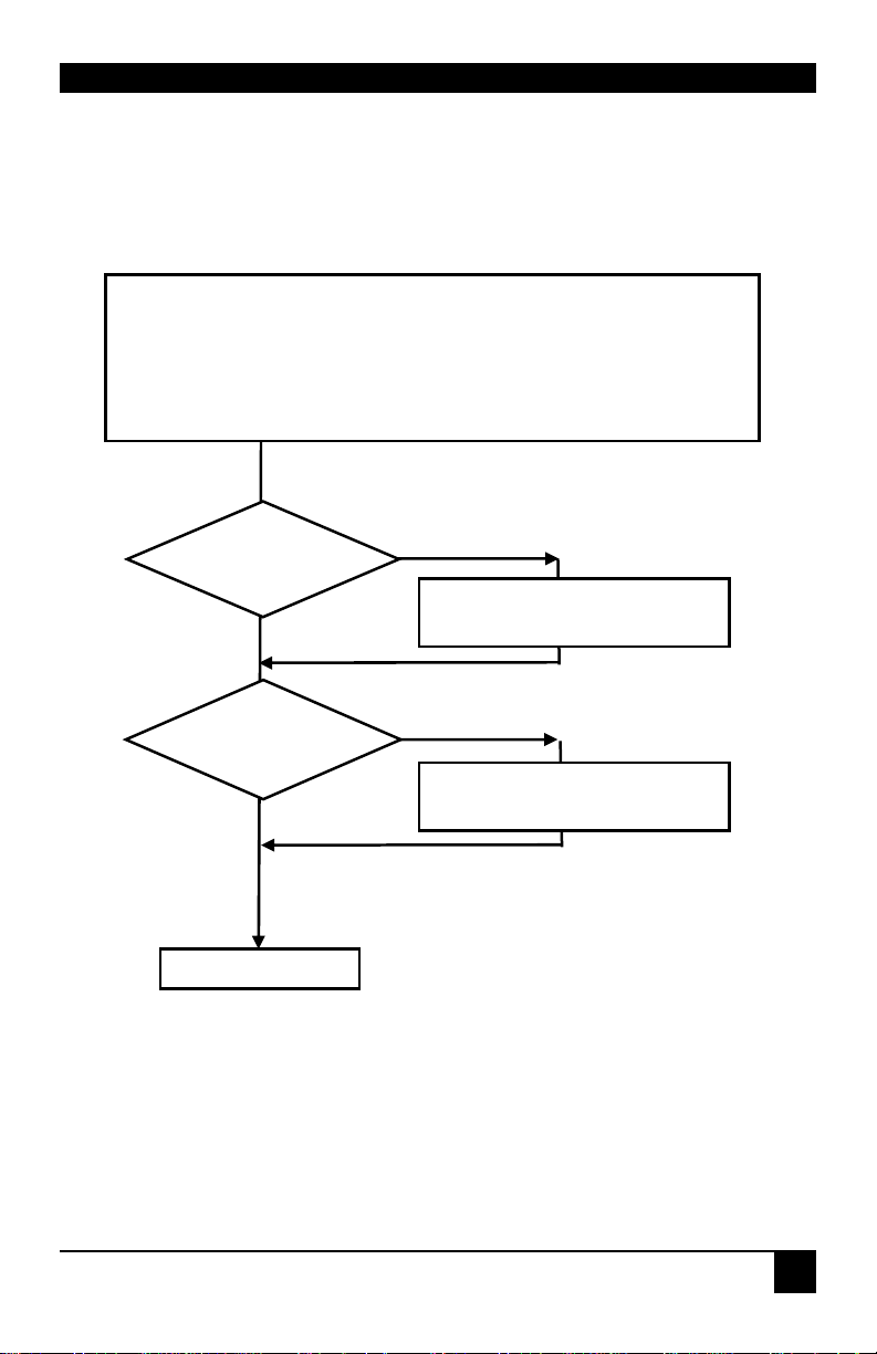
Install system
1. Quick Setup
This section briefly describes how to install your Repeater/Cross- Repeater system. Unless
you are an experienced user, we recommend that you follow the full procedures described in
the rest of this manual.
1. Connect Local unit to CPU or switch.
2. Connect Local unit to Repeater and Repeater to Remote Unit using
matching interconnection cable (CATx or Fiber)
3. Connect Remote unit to KVM.
4. Power up the system.
NO
Power LED
illuminated?
Check p.s.u.’s and connection
YES
Link LED
illuminated?
YES
Done
to power outlet
NO
Check the CATx/Fiber cable,
and CATx/Fiber connectors
Rev. : 09/25/2012
7
Page 8

REPEATER/CROSS- REPEATER
2. Overview
2.1 Introduction
A KVM Extender is used, to extend the distance between a CPU and its Keyboard / Monitor /
Mouse considerably. The allowed distance is limited by the physics and the make of the
cables.
If the total distance expires the allowed distance, Repeater may double the total allowed
distance.
In some environments, the signal path may be inhomogeneous. This means, a part might be
based on CATx, another part in Multimode. The Cross- Repeater hereby allow to convert
from one medium to another, without laborious regaining the original signals and resending
them.
The Repeater/Cross- Repeater described in this manual are especially designed for the DVXi
KVM Extender Family. Operation with other products is not possible.
2.2 Glossary
The following terms are used in this guide:
CATx
Fiber
Singlemode
Multimode
KVM
Console
Singlehead An extender system that supports one monitor + Keyboard/Mouse
Dualhead An extender system that supports two monitors + Keyboard/Mouse
DVI
PSU
HID
8
Any Category 5, 5e, 6 or higher cable, solid wires type AWG24.
Singlemode or Multimode fiber cable.
9µ Singlemode-fiber cable
62,5µ Multimode- or
50µ Multimode-fiber cable
Keyboard, Video and Mouse.
Keyboard, Mouse and Monitor
Digital Video standard, installed by Digital Display Working Group
(www.ddwg.org) R, G, B, CLOCK in a data stream with up to
3x 1,6 Gbit/sec. Signals are TMDS Level.
The desktop power supply connected to the Repeater/Cross- Repeater.
Human Interface Devices are units, which are used for human access
to the CPU. They are a USB-device class of its own (e.g. Memory
Devices etc.). Besides of keyboard and mouse also touchscreen, light
pen, fingerprint sensor, graphic tablets etc. are HID devices.
Rev. : 09/25/2012
Page 9
OVERVIEW
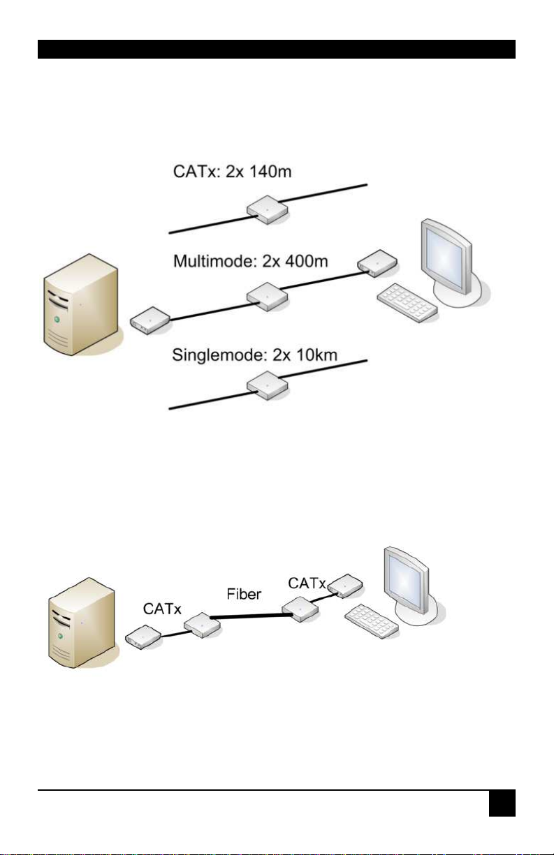
2.3 Example of a Repeater/Cross- Repeater
System
Installation as Repeater to double the total allowed distance
Installation as Cross- Repeater for inhomogeneous cable path
Rev. : 09/25/2012
9
Page 10

REPEATER/CROSS- REPEATER
2.4 Features
The Repeater/Cross- Repeater offer the following features:
• Support for DVXi KVM- and Media- Extender (all devices)
• Support for Draco™ KVM- and Media- Extender (all devices)
• When installing the Repeater device in the middle of a link, it will allow to double the
total distance. (e.g. CATx up to 2x140m = 280m). Under all other circumstances, the
cable on each side of the Repeater/Cross- Repeater may have the usual maximum
distance (e.g. CATx up to 140m, Multimode 50µ up to 400m, ...).
• When installing a Cross- Repeater device, the cable on each side of the Repeater/Cross-
Repeater may have the usual maximum distance (e.g. CATx up to 140m, Multimode 50µ
up to 400m, ...).
Attention!
actually DVXi CATx and Fiber devices must not be used assorted. This
means, it’s not allowed, to connect a DVXi CATx Local Unit with a DVXi
Fiber Remote Unit. So actually Cross- Repeater can be used only in pairs.
For Dual- Head devices you need two pieces Repeater (one for each of the
two interconnection cables). A Dual Cross- Repeater CATx to Fiber
(Multimode or Singlemode) is available.
• The maximum screen resolution as well as the support of other interfaces like USB-HID,
serial, audio, ... only depends on the type of used Extender.
• Status indicator LEDs on each device.
• Small footprint chassis.
• Rack mount options available.
• Universal switch mode p.s.u. included.
10
Rev. : 09/25/2012
Page 11

OVERVIEW
2.5 Product Range
Repeater/Cross- Repeater
K471-CT CATx Repeater to raise the total allowed distance to up to
280m
K471-MM Multimode Repeater to raise the total allowed distance to
up to 800m
K471-SS Singlemode Repeater to raise the total allowed distance to
up to 20km
K471-CM CATx/Multimode Dual Cross Repeater to convert from
2x CATx to 2x Multimode or back
K471-DM CATx/Multimode Cross Repeater to convert from CATx to
Multimode or back
K471-CS CATx/Singlemode Cross Repeater to convert from CATx
to Singlemode or back
K471-DS CATx/Singlemode Dual Cross Repeater to convert from
2x CATx to 2x Singlemode or back
K471-MS Multimode/Singlemode Cross Repeater to convert from
Multimode to Singlemode or back
Zubehör
473-5G 19”/1HE Rackmout- Kit to mount up to 5 devices
473-1K
473-2K
Mounting plate to mount by screws
Mounting plate to mount by snap-on
2.6 How to Use This Guide
This guide describes the installation and configuration of the Repeater/Cross- Repeater.
Although the connection and operation of the system is relatively straightforward, you should
consider the following before getting started:
Connection & Compatibility
If you have purchased an Repeater/Cross- Repeater Kit, this will contain the device and the
universal switch mode p.s.u. to install your Repeaters/Cross- Repeater. Please see also:
Package Contents (page 12)
Rev. : 09/25/2012
11
Page 12

REPEATER/CROSS- REPEATER
3. Installation
For first-time users, we recommend that you carry out a test placement, confined to a single
room, before commencing full installation. This will allow you to identify and solve any
cabling problems, and experiment with the Repeater/Cross- Repeater more conveniently.
3.1 Package Contents
You should receive the following items in your extender package (all types):
• Repeater/Cross- Repeater
• 5V DC universal power supply
• German type power cord
• User manual (Quick Setup)
If anything is missing, please contact Technical Support (see Appendix F – Calling
Technical Support).
12
Rev. : 09/25/2012
Page 13

INSTALLATION
3.2 Interconnection Cable Requirements
To install the Repeater/Cross- Repeater you will need:
• CATx Cable: Recommended cable: S/UTP (Cat5) according EIA/TIA 56A, TSB 36 or
Digital STP 17-03170. Four pairs AWG 24. connection according EIA/TIA 568A
(10BaseT). Use of cables from a higher category (Cat5e, Cat6, Cat7) is possible..
The use of unshielded CATx Cable is possible, because of
the higher electromagnetic noise/sensitivity the device class
may not be reached, the compliance with CE regulations is
not longer guaranteed.
The use of flexible Cables (Patch cable) Type AWG26/8 is possible.
Because of the higher loss of the stranded cables, the maximum distance is
reduced to app. half the value of solid cables.
• Fiber Cable: Two strands of fiber are required for singlehead devices, four strands for
Dualhead devices.
Please note, that the allowed distance will depend on device type AND on
used fiber type.
• Recommended cables:
Multimode type 50/125µ allowed distance app. 400m (1,300ft)
Multimode type 62.5/125µ allowed distance app. 200m (650ft)
Singlemode type 9/125µ allowed distance app. 10km (32,750ft)
A point to point connection is required. Having one or more patch panels
in the line is possible and allowed. Not allowed is a connection from the
Fiber link interface (LC) to any other products, especially
telecommunications or network equipment.
Our experiences show, that Singlemode devices regularly work well on
Multimode Fibers where vice versa it will never do. In addition we found,
that Singlemode devices on Multimode fibers may extend the allowed
distance on Multimode fibers to twice the regular length. Anyway this
cannot be guaranteed and must be evaluated by the end-user at his own
expense.
• Power Supply: Connect the supplied 5V/DC power supplies to the Plug terminal on the
rear of both local and remote units.
Rev. : 09/25/2012
13
Page 14

REPEATER/CROSS- REPEATER
3.3 System Setup
To install your Repeater/Cross- Repeater system:
1. Switch off all devices.
2. Connect the interconnect cable to the INTERCONNECT socket(s) of the Local Unit and
the Repeater/Cross- Repeater
3. Connect the interconnect cable to the INTERCONNECT socket(s) of the Remote Unit
and the Repeater/Cross- Repeater
If you have bought a Cross Repeater, your device will have two CATx
connectors but only one fiber connector. Possibly you have to swap the
fiber GBIC from one port to the other to make the unit working properly.
To do this, please refer to installation instruction on page 19.
If you have bought a Dual Cross Repeater, your device will have two
CATx connectors and two fiber connectors. The units are marked as
„Local“ or „Remote“. For a correct installation, please refer to
installation instruction on page 19. If you want to upgrade a Cross
Repeater to Dual Cross Repeater, you need to reconfigure the jumper
settings.To do this, please refer to Setup at the Repeater/Cross- Repeater
on page 18.
4. Connect the 5V power supply unit to power the unit.
Only use the power supply originally supplied with this
equipment or a manufacturer-approved replacement.
5. For a dual head system, connect in the same way like described under 2. and 3. the
CATx/Fiber cables for the secondary monitor.
6. Power up the system
14
Rev. : 09/25/2012
Page 15

3.4 Device Views
Repeater/Cross- Repeater CATx view
To Local Unit To Remote Unit 5V universal switch
To Local Unit To Remote Unit
INSTALLATION
mode p.s.u.
Repeater/Cross- Repeater Fiber view
Rev. : 09/25/2012
15
Page 16

REPEATER/CROSS- REPEATER
3.5 Diagnostics
Each Repeater/Cross- Repeater is fitted with three indicator LEDs: Power, Data Error, Link
Status: The Power LEDs are next to the Power socket.
The location of the LEDs is shown below:
Diagnostic LED
Data Error
Diagnostic LED
Link Status
Diagnostic LED
Power
Diagnostic LED
Link Status
Diagnostic - LEDs at the Repeater/Cross- Repeater
LED Appearance Diagnostics
Power LED
(Red LED)
Link Status
(Green LED)
Data Error
(Green LED)
Off
On
Blinking
On
Indicator LED actually without function
Device not ready
Device ready
No INTERCONNECT connection via CATx or
fiber cable
Device ready
16
Rev. : 09/25/2012
Page 17

SERVICE SETUP
4. Service Setup
For most applications, you shouldn't need not to make any adjustments to set up your
Repeater/Cross- Repeater. Under some special circumstances it could be necessary to setup
configuration specials.
For some applications, you may need to open the Local Unit and/or the Remote Unit.
Unscrew the Philips-type screws at both sides at the bottom of the device. Unscrew the UNC
type screws at both sides of the monitor connectors. Carefully displace the lower and upper
shells of the case.
Fastening
screw on the
bottom of the
device
Fastening
screw on the
bottom of the
device
Rev. : 09/25/2012
17
Page 18

REPEATER/CROSS- REPEATER
4.1 Setup at the Repeater/Cross- Repeater
After unscrewing and opening the upper shell, please place the device in this orientation: with
the CATx/fiber connectors to the left and the Fiber connectors to the right (eventually not
equipped with GBICs).
The main PCB then will look like this:
JP1
JPA B
Use the diagram to locate jumpers.
Operating mode Repeater or Cross- Repeater
If you want to alter the mode of operation after the date of purchase, e.g. from Repeater to
Cross- Repeater or vice versa, you need (probably) to install optical Transceiver (GBICs) and
reconfigure the device.
Operating Mode JP1 JPA B
Repeater or Fiber- Cross- Repeater
CATx/Fiber Cross- Repeater
18
Rev. : 09/25/2012
Page 19

SERVICE SETUP
Operating mode Dualhead Cross- Repeater
If you want to alter the mode of operation after the date of purchase, e.g. to use it as a
Dualhead Cross- Repeater, you need (probably) to install optical Transceiver (GBICs) and
reconfigure the device.
Operating mode JP1 JPA B
Dualhead Cross- Repeater Local CATx
Dualhead Cross- Repeater Remote CATx
4.2 installation instruction
Basically you need to pay attention to attach at connectors marked with
“A” only cables which link to a Local Unit and to attach at connectors
marked with „B“ only cables which link to a Remote Unit.
CATx or Fiber Repeater, Multimode/Singlemode Cross- Repeater
Remote
Unit
The Local Unit is connected via CATx (Fiber) connector A, the Remote Unit is connected via
CATx (Fiber) connector B.
Rev. : 09/25/2012
19
Local
Unit
Page 20

REPEATER/CROSS- REPEATER
Local
Remote
CATx / Fiber Cross- Repeater
Local
Remote
Unit
The Local Unit is connected via CATx (Fiber) connector A, The fiber connector B is
connected to the fiber connector A of the second Repeater. The Remote Unit is connected via
CATx (Fiber) connector B.
Reconfiguration of a Cross Repeater from „Local“ to „Remote“
or vice versa
The „Local“ device must carry the fiber GBIC in the connector B, the „Remote“ device in the
connector A. If the GBICs in your devices are plugged incorrect, you may alter the
configuration easily:
• flap the shackle at the GBIC downwards
• now pull the GBIC, using the shackle, out of the cage
• plug the GBIC with soft force into the other cage until it snaps into place
• flap the shackle at the GBIC upwards to lock the GBIC
Do not try to pull the GBIC out of the cage while the shackle
remains in the lock position (not flapped downwards). As long
as the shackle is flapped upwards, the GBIC is locked. Rough
pulling the GBIC out of the cage without flapping the shackle
downwards may result in damages at the GBIC and/or at the
device.
20
Rev. : 09/25/2012
Page 21

TROUBLESHOOTING
Dualhead Cross- Repeater
Local
Remote
Unit
The Cross Repeater look the same for the Local and the remote placement. Because of
internal jumper settings the data direction is fixed. Please note to install the device, marked
with „Cross Repeater Local CATX“ at a position where the CATx cable link to the Local
Unit and the device, marked with „Cross Repeater Remote CATx“ at a position where the
CATx cable link to the Remote Unit.
5. Troubleshooting
Monitor
There isn’t a picture.
Check the power supply connection at the local and remote unit and at the
Repeater/Cross- Repeater. Is the Power (Red LED) at the devices illuminated (see
page 15)? If not, the internal power-supply may be damaged or there may be an
internal error.
Check that the INTERCONNECT cable is connected at the Local Unit and the
Remote Unit and at the Repeater/Cross- Repeater. Is the Link Status LED
illuminated (see page 15)? If not, there may be a problem with the Interconnection
cable:
Rev. : 09/25/2012
21
Page 22

REPEATER/CROSS- REPEATER
Appendix A: Example Applications
This section illustrates some specific applications using the Repeater/Cross- Repeater:
• Repeater in Industrial Plant to raise the allowed distance of the interconnection
Repeater in Industrial Plant
22
Rev. : 09/25/2012
Page 23

APPENDIX A: EXAMPLE APPLICATIONS
• Repeater/Cross- Repeater in public buildings.
In some environments – especially public buildings - , the signal path may be
inhomogeneous. This means, a part might be based on CATx, another part in Multimode. The
Cross- Repeater hereby allow to convert from one medium to another, without laborious
regaining the original signals and resending them.
Cross- Repeater in public building
Rev. : 09/25/2012
23
Page 24

REPEATER/CROSS- REPEATER
• Repeater/Cross- Repeater for interconnection of two buildings.
It is not allowed according VDE to make the interconnection of two buildings with CATx
Cables. Because of this, the interconnection must be done in fiber. A server from the server
room shall be connected with the user console in the plant. The Cross- Repeater hereby allow
to convert from one medium to another, without laborious regaining the original signals and
resending them.
Cross- Repeater for interconnection of two buildings
24
Rev. : 09/25/2012
Page 25

APPENDIX B: RACK MOUNT OPTIONS
Appendix B: Rack Mount Options
Repeater/Cross- Repeater units can be mounted in a 19” rack using the mounting kit.
Mounting Instruction Rackmount-Kit 473-5G
Using the Rackmount-Kit 473-5G, up to 4 devices of the device size 80x110x29mm can be
mounted into a 19“-Server Rack. The Rackmount Kit requires 1U Rackspace. Blindplates (in
the list of parts delivered) allow to cover unused device positions.
Rackmount-Kit 473-5G – List of parts delivered:
base plate
10 pieces spacer – M2,5x2
4 pieces blind plate
10 pieces M2,5x5 Philips type
countersunk screws
Mounting instruction:
• Align the holes on the base plate with the vacant screw holes on the base of the device.
• Fasten the base of the unit to the plate of the mounting kit
Only use the supplied, short screws, to prevent damages on
the PCB’s
• Close the remaining gaps with blanking plates.
Rev. : 09/25/2012
25
Page 26

REPEATER/CROSS- REPEATER
Einbau 2 Geräte
Einbau 3 Geräte
mounting 3 devices
mounting 5 devices
Einbau 4 Geräte
The Rackmount- Kit 473-5G allows, to mount a different count of devices (1…5 pieces):
Einbau 1 Gerät
mounting 1 device
mounting 2 devices
mounting 4 devices
Einbau 5 Geräte
26
Rev. : 09/25/2012
Page 27

APPENDIX D: CALLING TECHNICAL SUPPORT
Appendix D: Calling Technical Support
If you determine that your Repeater/Cross- Repeater is malfunctioning, do not attempt to
alter or repair it. It contains no user-serviceable parts. Contact Technical Support at.
Before you do, make a record of the history of the problem. We will be able to provide more
efficient and accurate assistance if you have a complete description, including:
• The firmware-revision level printed on the bottom of the Extender (very important,
especially for keyboard and mouse problems); The Repeater/Cross- Repeater’s firmware
revision level:
Version Number Format:
Board: xxLO/RE Myyy Pzzz Auuu Gvvvvvv
Transceiver: C/M/S xx Pyy Mzz
Keyboard/Mouse: P/U xx Vyyy
• The nature and duration of the problem.
• When the problem occurs.
• The components involved in the problem—that is, what type of computers, what type of
keyboard, brand of mouse, make and model of monitor, type and make of cable, etc.
• Any particular application that, when used, appears to create the problem or make it
worse.
• The results of any testing you’ve already done.
To solve some problems, it might be necessary to upgrade the Extender’s firmware. If this
turns out to be the case for your difficulty, our Technical Support technicians will arrange for
you to receive the new firmware and will tell you how to install it.
Shipping and Packaging
If you need to transport or ship your Repeater/Cross- Repeater:
• Package it carefully. We recommend that you use the original container.
• If you are shipping it for repair, please include the Unit’s external power supplies. If you
are returning it, please include everything you received with it. Before you ship the
Extender back to your dealer for repair or return, contact him to get a Return
Authorization (RA) number.
Rev. : 09/25/2012
27
Page 28

REPEATER/CROSS- REPEATER
Appendix F: Specifications
Power
Voltage
Power required
90-240VAC-0.5A-47-63Hz/5VDC-2000 mA
Repeater/ Cross- Repeater Unit : max. 5V/750mA
operation mode CATx – Repeater: ca. 500mA
operation mode Fiber Repeater ca. 300mA
operation mode Cross Repeater ca. 750mA
Interface
(Depending on type of device)
LC
RJ45
Multimode or Singlemode – depending on device
1000 MBit high speed transmission. Wiring according
to EIA/TIA 568B Gigabit Ethernet.
Maximum Length of Interconnection Cable (CATx)
CATx Installation cable AWG24
CATx Patchcable AWG26/8
140m (400ft)
70m (200ft)
Type of Interconnection Cable (CATx)
CATx Installation cable AWG24
CATx Patchcable AWG26/7
S/UTP (Cat5) cable acc. EIA/TIA 56A, TSB 36 or
Digital STP 17-03170. Four pairs AWG 24. Wiring
acc. EIA/TIA 568A (1000BaseT).
S/UTP (Cat5) cable acc. EIA/TIA 56A, TSB 36 or
Digital STP 17-03170. Four pairs AWG 26/7. Wiring
acc. EIA/TIA 568A (1000BaseT).
28
Rev. : 09/25/2012
Page 29

APPENDIX F: SPECIFICATIONS
Maximum Length of Interconnection Cable (Fiber - LC Connectors)
Singlemode 9 µm
Multimode 50µm
Multimode 62.5µm
Size and Shipping Weight
Repeater/Cross- Repeater
Shipping box
Environmental
Operating Temperature
Storage Temperature
Relative Humidity
10.000m (32.750ft)
400m (1.300ft)
200m (650ft)
80 x 110 x 29mm (3”x4.3”x1.1”)
Weight: 0,2kg (0.6lb)
165x165x110mm (6.5”x6.5”x4.3”)
Weight: 0.6 kg (1.3lb)
41 to 113°F (5 to 45 °C)
-13 to 140°F (-25 to 60 °C)
max. 80% non-condensing
Rev. : 09/25/2012
29
Page 30

REPEATER/CROSS- REPEATER
Appendix G: Connectors
Repeater/Cross- Repeater Connector Pin outs
Power Supply
Pin Signal
inner +5V
outer GND
CATx- Interface
Pin out according to EIA/TIA 568A (1000BaseT).
1 8
Pin Pin
1 D1+ 5 D32 D1- 6 D23 D2+ 7 D4+
4 D3+ 8 D4-
30
Rev. : 09/25/2012
Page 31

NOTES
 Loading...