

Page 1

PM-1028-R20
PC/104 4/8-Port RS-232 Module
PCB Ver2.0
Manual Revision 2.0
Jan, 24, 2006
@Copyright 2006 by ICP Electronics Inc. All Rights Reserved.
PM-1028-R20 driver & user’s manual is the same as PM-
1028.
The information in this document is subject to change without
prior notice in order to improve reliability, design and function
and does not represent a commitment on the part of the manufacturer.
In no event will the manufacturer be liable for direct, indirect,
special, incidental, or consequential damages arising out of the
use or inability to use the product or documentation, even if advised of the possibility of such damages.
This document contains proprietary information protected by
copyright. All rights are reserved. No part of this manual may
be reproduced by any mechanical, electronic, or other means
in any form without prior written permission of the manufacturer.
Trademarks
PM-1028 is a registered trademark of ICP Electronics Inc., IBM
PC is a registered trademark of International Business
Machines Corporation. Intel is a registered trademark of Intel
Corporation. AMI is a registered trademark of American
Megatrends Inc. , Other product names mentioned herein are
used for identification purposes only and may be trademarks
and/or registered trademarks of their respective companies.
Support
Any questions regarding the content of this manual or related
issues can be e-mailed to us directly at:
SUPPORT@IEI.COM.TW
1
Page 2

Contents
1. Introduction ........................................................................................... 3
1.1 Specifications ........................................................................ 3
1.2 PM-1028 Package Contents ................................................. 4
2. Installation............................................................................................. 5
2.1 Board Layout......................................................................... 5
2.2 Board Layout......................................................................... 6
2.3 Interrupt vector address setting ............................................ 8
2.4 COM Port base I/O address setting ...................................... 9
2.5 COM Port IRQ select .......................................................... 11
2.6 IRQ sharing mode select .................................................... 11
3. Connection.......................................................................................... 12
3.1 Port RS-232 Connectors..................................................... 12
3.2 PC/104 Expansion Bus ........................................................1
4. Device Driver Installation.................................................................... 16
4.1 PM-1028 Device Driver Installation..................................... 16
4.2 PM-1028 resource setup..................................................... 19
4.3 Uninstall PM-1028 Device Driver ........................................ 24
2
4
Page 3

1
Introduction
The PM-1028 is a PC/104-compliant 4-port or 8-port RS-232
module
integrated on board. Its UART is compatible with the 16C550.
PM-1028 provides two ways of interrupt control mechanism –
shared or independent IRQ. Besides, its IO address and
interrupt status address are also selectable by jumpers.
1.1 Specifications:
Bus: PC/104.
•
Interrupt Level: 3, 4, 5, 7, 9, 10, 11, 12.
•
Chipset: TI 16C554A.
•
Baud Rate: up to 921.6K bps (at 14.745Mhz clock input).
•
Serial ports: 8 16C550-compatible UARTs -- PM-1028-8,
•
with one TI 16C544Ahigh performance serial I/O chip
4 16C550-compatible UARTs -- PM-1028-4
Shared or Independent Interrupt.
•
Selectable Interrupt vector address.
•
Selectable I/O address.
•
Power Consumption: +5V @ 0.6A max.
•
Operating Temperature: 0° ~ 60 ° C.
•
3
Page 4

1.2 PM-1028 package contents
PM-1028 package includes the following items:
1 x User Manual
•
1 x PM-1028 x 1
•
2 x Serial port cables ( 40 pin, 4 DB-9 ) for the PM-1028-8
•
1 x Serial port cable ( 40 pin, 4 DB-9 ) for the PM-1028-4
•
1 x CD-ROM Driver
•
If any of theitems listed above are missing or damaged, please
contact the dealer who you purchased the product from. Be
sure to save the shipping materials and carton in case you
want to ship or store the product in the future.
4
Page 5

2
Installation
This chapter describes how to install the PM-1028.
2.1 Hardware Installation
Installation of the PC/104 modules on CPU card is quick and
simple. The following steps describe how to mount the PC/104
modules.
Note: Ground yourself to remove any static charge before
touching your PM-1028. You can do it by using a grounded wrist
strap at all times or by frequently touching any conducting
materials that are connected to the ground.
1. Turn the power off
2. Plug the PC/104 module in to the connectors on the CPU
card carefully
3. Secure the PC/104 module with the four mounting spacers
and screws
4. Set the jumper settings
5. Attach the cables
6. Turn the power on
5
Page 6

2.2 Board Layout
6
Page 7
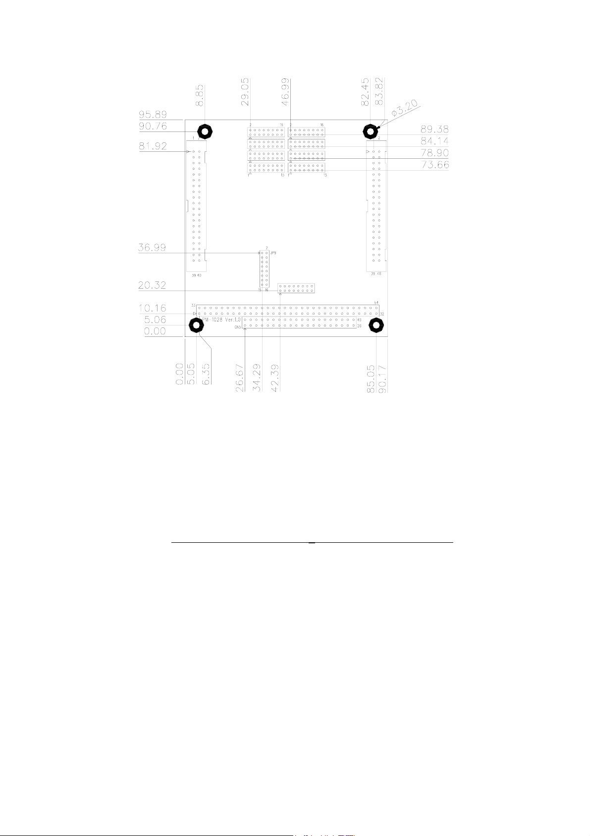
Board Dimension (mm)
7
Page 8
2.3 Interrupt Status address setting
• JP9: Interrupt status address setting
Interrupt Status
Address
200H
210H
220H
230H
240H
250H
260H
270H
280H
290H
2A0H
2B0H
2C0H
2D0H
2E0H
2F0H
*300H OFF ON ON ON ON
310H
320H
330H
340H
350H
360H
370H
380H
390H
3A0H
3B0H
3C0H
3D0H
3E0H
3F0H
*: Default
9-10 7-8 5-6 3-4 1-2
ON ON ON ON ON
ON ON ON ON OFF
ON ON ON OFF ON
ON ON ON OFF OFF
ON ON OFF ON ON
ON ON OFF ON OFF
ON ON OFF OFF ON
ON ON OFF OFF OFF
ON OFF ON ON ON
ON OFF ON ON OFF
ON OFF ON OFF ON
ON OFF ON OFF OFF
ON OFF OFF ON ON
ON OFF OFF ON OFF
ON OFF OFF OFF ON
ON OFF OFF OFF OFF
OFFONONONOFF
OFF ON ON OFF ON
OFF ON ON OFF OFF
OFF ON OFF ON ON
OFF ON OFF ON OFF
OFF ON OFF OFF ON
OFF ON OFF OFF OFF
OFF OFF ON ON ON
OFF OFF ON ON OFF
OFF OFF ON OFF ON
OFF OFF ON OFF OFF
OFF OFF OFF ON ON
OFF OFF OFF ON OFF
OFF OFF OFF OFF ON
OFF OFF OFF OFF OFF
8
Page 9

2.4 COM Port I/O base address setting
JP10: COM Port I/O base address setting
•
Base Address 11-12 9-10 7-8 5-6 3-4 1-2
*200-207H ON ON ON ON ON ON
208-20FH
210-217H
218-21FH
220-227H
228-22FH
230-237H
238-23FH
240-247H
248-24FH
250-257H
258-25FH
260-267H
268-26FH
270-277H
278-27FH
280-287H
288-28FH
290-297H
298-29FH
2A0-2A7H
2A8-2AFH
2B0-2B7H
2B8-2BFH
2C0-2C7H
2C8-2CFH
2D0-2D7H
2D8-2DFH
2E0-2E7H
2E8-2EFH
2F0-2F7H
2F8-2FFH
300-307H
308-30FH
310-317H
ON ON ON ON ON OFF
ON ON ON ON OFF ON
ON ON ON ON OFF OFF
ON ON ON OFF ON ON
ON ON ON OFF ON OFF
ON ON ON OFF OFF ON
ON ON ON OFF OFF OFF
ON ON OFF ON ON ON
ON ON OFF ON ON OFF
ON ON OFF ON OFF ON
ON ON OFF ON OFF OFF
ON ON OFF OFF ON ON
ON ON OFF OFF ON OFF
ON ON OFF OFF OFF ON
ON ON OFF OFF OFF OFF
ON OFF ON ON ON ON
ON OFF ON ON ON OFF
ON OFF ON ON OFF ON
ON OFF ON ON OFF OFF
ON OFF ON OFF ON ON
ON OFF ON OFF ON OFF
ON OFF ON OFF OFF ON
ON OFF ON OFF OFF OFF
ON OFF OFF ON ON ON
ON OFF OFF ON ON OFF
ON OFF OFF ON OFF ON
ON OFF OFF ON OFF OFF
ON OFF OFF OFF ON ON
ON OFF OFF OFF ON OFF
ON OFF OFF OFF OFF ON
ON OFF OFF OFF OFF OFF
OFFONONONONON
OFFONONONONOFF
OFFONONONOFFON
9
Page 10

318-31FH
320-327H
328-32FH
330-337H
338-33FH
340-347H
348-34FH
350-357H
358-35FH
360-367H
368-36FH
370-377H
378-37FH
380-387H
388-38FH
390-397H
398-39FH
3A0-3A7H
3A8-3AFH
3B0-3B7H
3B8-3BFH
3C0-3C7H
3C8-3CFH
3D0-3D7H
3D8-3DFH
3E0-3E7H
3E8-3EFH
3F0-3F7H
3F8-3FFH
*: Default
OFF ON ON ON OFF OFF
OFF ON ON OFF ON ON
OFF ON ON OFF ON OFF
OFF ON ON OFF OFF ON
OFF ON ON OFF OFF OFF
OFF ON OFF ON ON ON
OFF ON OFF ON ON OFF
OFF ON OFF ON OFF ON
OFF ON OFF ON OFF OFF
OFF ON OFF OFF ON ON
OFF ON OFF OFF ON OFF
OFF ON OFF OFF OFF ON
OFF ON OFF OFF OFF OFF
OFF OFF ON ON ON ON
OFF OFF ON ON ON OFF
OFF OFF ON ON OFF ON
OFF OFF ON ON OFF OFF
OFF OFF ON OFF ON ON
OFF OFF ON OFF ON OFF
OFF OFF ON OFF OFF ON
OFF OFF ON OFF OFF OFF
OFF OFF OFF ON ON ON
OFF OFF OFF ON ON OFF
OFF OFF OFF ON OFF ON
OFF OFF OFF ON OFF OFF
OFF OFF OFF OFF ON ON
OFF OFF OFF OFF ON OFF
OFF OFF OFF OFF OFF ON
OFF OFF OFF OFF OFF OFF
10
Page 11

COM Port I/O address
COM Port I/O address
COM1
COM2
COM3
COM4
COM5
COM6
COM7
COM8
Base Address + 00H
Base Address + 08H
Base Address + 10H
Base Address + 18H
Base Address + 20H
Base Address + 28H
Base Address + 30H
Base Address + 38H
2.5 COM Port IRQ selection
JP1: COM4 IRQ setting, JP2: COM8 IRQ setting
JP3: COM3 IRQ setting, JP4: COM7 IRQ setting
JP5: COM2 IRQ setting, JP6: COM6 IRQ setting
JP7: COM1 IRQ setting, JP8: COM5 IRQ setting
IRQ 1-2 3-4 5-6 7-8 9-10 11-12 13-14 15-16
ON OFF OFF OFF OFF OFF OFF OFF
3
OFF
4
OFF OFF
5
OFF OFF OFF
7
OFF OFF OFF OFF
9
OFF OFF OFF OFF OFF
10
OFF OFF OFF OFF OFF OFF
11
OFF OFF OFF OFF OFF OFF OFF
12
Default setting: COM1 – IRQ3, COM2 – IRQ4, COM3 – IRQ5,
COM4 – IRQ7, COM5 – IRQ9, COM6 – IRQ10, COM7 –
IRQ11COM8 – IRQ12
ON OFF OFF OFF OFF OFF OFF
ON OFF OFF OFF OFF OFF
ON OFF OFF OFF OFF
ON OFF OFF OFF
ON OFF OFF
ON OFF
ON
2.6 IRQ sharing mode selection
JP10: IRQ sharing mode selection
•
Mode 13-14 15-16
*Independent IRQ Mode
COM1~COM8 share 1 IRQ (assigned by JP7)
11
ON ON
OFF ON
Page 12

*: Default
12
Page 13

3
Connection
This chapter describes how to connect peripherals, switches
and indicators to the PM-1028 board.
3.1 RS-232 Connector
The serial ports are high speed NS16C550 compatible UART
ports with Read/Receive 16 byte FIFO.
• CN1: COM1 ~ COM4 serial port connectors.
PIN NO DESCRIPTION PIN NO DESCRIPTION
1
3
5
7
9
11
13
15
17
19
21
23
25
27
29
31
33
35
37
39
DCD (COM4)
RXD (COM4)
TXD (COM4)
DTR (COM4)
GND (COM4)
DCD (COM3)
RXD (COM3)
TXD (COM3)
DTR (COM3)
GND (COM3)
DCD (COM2)
RXD (COM2)
TXD (COM2)
DTR (COM2)
GND (COM2)
DCD (COM1)
RXD (COM1)
TXD (COM1)
DTR (COM1)
GND (COM1)
2
4
6
8
10
12
14
16
18
20
22
24
26
28
30
32
34
36
38
40
DSR (COM4)
RTS (COM4)
CTX (COM4)
RI (COM4)
GND (COM4)
DSR (COM3)
RTS (COM3)
CTX (COM3)
RI (COM3)
GND (COM3)
DSR (COM2)
RTS (COM2)
CTX (COM2)
RI (COM2)
GND (COM2)
DSR (COM1)
RTS (COM1)
CTX (COM1)
RI (COM1)
GND (COM1)
13
Page 14

• CN2: COM5 ~ COM8 serial port connectors.
PIN NO DESCRIPTION PIN NO DESCRIPTION
1
3
5
7
9
11
13
15
17
19
21
23
25
27
29
31
33
35
37
39
DCD (COM8)
RXD (COM8)
TXD (COM8)
DTR (COM8)
GND (COM8)
DCD (COM7)
RXD (COM7)
TXD (COM7)
DTR (COM7)
GND (COM7)
DCD (COM6)
RXD (COM6)
TXD (COM6)
DTR (COM6)
GND (COM6)
DCD (COM5)
RXD (COM5)
TXD (COM5)
DTR (COM5)
GND (COM5)
2
4
6
8
10
12
14
16
18
20
22
24
26
28
30
32
34
36
38
40
DSR (COM8)
RTS (COM8)
CTX (COM8)
RI (COM8)
GND (COM8)
DSR (COM7)
RTS (COM7)
CTX (COM7)
RI (COM7)
GND (COM7)
DSR (COM6)
RTS (COM6)
CTX (COM6)
RI (COM6)
GND (COM6)
DSR (COM5)
RTS (COM5)
CTX (COM5)
RI (COM5)
GND (COM5)
14
Page 15

3.2 PC/104 Expansion Bus
The PC/104 expansion bus on the PM-1028enables you to
attach the PM-1028 to the PC/104 slot on the target system.
The PC/104 bus has already become the industrial embedded
PC bus standard, so you can easily install thousands of
PC/104 modules from hundreds of vendors around the world.
There are two types of connectors on this board -- PC/104-64
and PC/104-40.
•PC/104-40 Connector
PIN NO DESCRIPTION PIN NO DESCRIPTION
1
2
3
4
5
6
7
8
9
10
11
12
13
14
15
16
17
18
19
20
GND
MCS16#
IOCS16#
IRQ10
IRQ11
IRQ12
IRQ15
IRQ14
DACK0#
DRQ0
DACK5#
DRQ5
DACK6#
DRQ6
DACK7#
DRQ7
VCC
MASTER#
GND
GND
21
22
23
24
25
26
27
28
29
30
31
32
33
34
35
36
37
38
39
40
GND
SBHE#
LA23
LA22
LA21
LA20
LA19
LA18
AL17
MEMR#
MEMW#
SD8
SD9
SD10
SD11
SD12
SD13
SD14
SD15
GND
15
Page 16

•PC/104-64 Connector
PIN NO DESCRIPTION PIN NO DESCRIPTION
1 IOCHCK# 33 GND
2 SD7 34 IRSTDRV
3 SD6 35 VCC
4 SD5 36 IRQ9
5 SD4 37 -5V
6 SD3 38 N/C
7 SD2 39 -12V
8 SD1 40 ZWS
9 SD0 41 +12V
10 IOCHRDY 42 GND
11 AEN 43 SMEMW#
12 LA19 44 SMEMR#
13 LA18 45 IOW#
14 LA17 46 IOR#
15 SA16 47 DACK3#
16 SA15 48 DRQ3
17 SA14 49 DACK1#
18 SA13 50 DRQ1
19 SA12 51 REFRESH#
20 SA11 52 SYSCLK
21 SA10 53 IRQ7
22 SA9 54 N/C
23 SA8 55 IRQ5
24 SA7 56 IRQ4
25 SA6 57 IRQ3
26 SA5 58 N/C
27 SA4 59 TC
28 SA3 60 BALE
29 SA2 61 VCC
30 SA1 62 OSC
31 SA0 63 GND
32 GND 64 GND
16
Page 17

4
Device Driver Installation
4.1 PM-1028 Device Driver Installation
NOTE: It is necessary to go into the BIOS setup and ensure that the
IRQs used by the PM-1028 are set to Legacy ISA only. Please refer to
your BIOS setup manual for more information.
To install the device driver for the PM-1028, run installation
wizard IEISETUP.EXE
Click “Next>”
17
Page 18

Click “Next>” and the installation wizard starts to copy files to
you hard disk.
After the files are copied, PMSETUP.EXE is auto launched to
the configure system resources for the PM-1028. You can
continue the resource configuration (ref. Section 4.2) or click
“Cancel” now and run PMSETUP.EXE later.
18
Page 19

Click “Finish” to complete the device driver installation.
19
Page 20

4.2 PM-1028 resource setup
At device driver installation, the installation wizard copied a
utility PMSETUP.EXE to your local hard disk and created a
shortcut link “PM-1028 Setup”.
To configure PM-1028 resource settings, click “PM-1028
Setup”.
20
Page 21
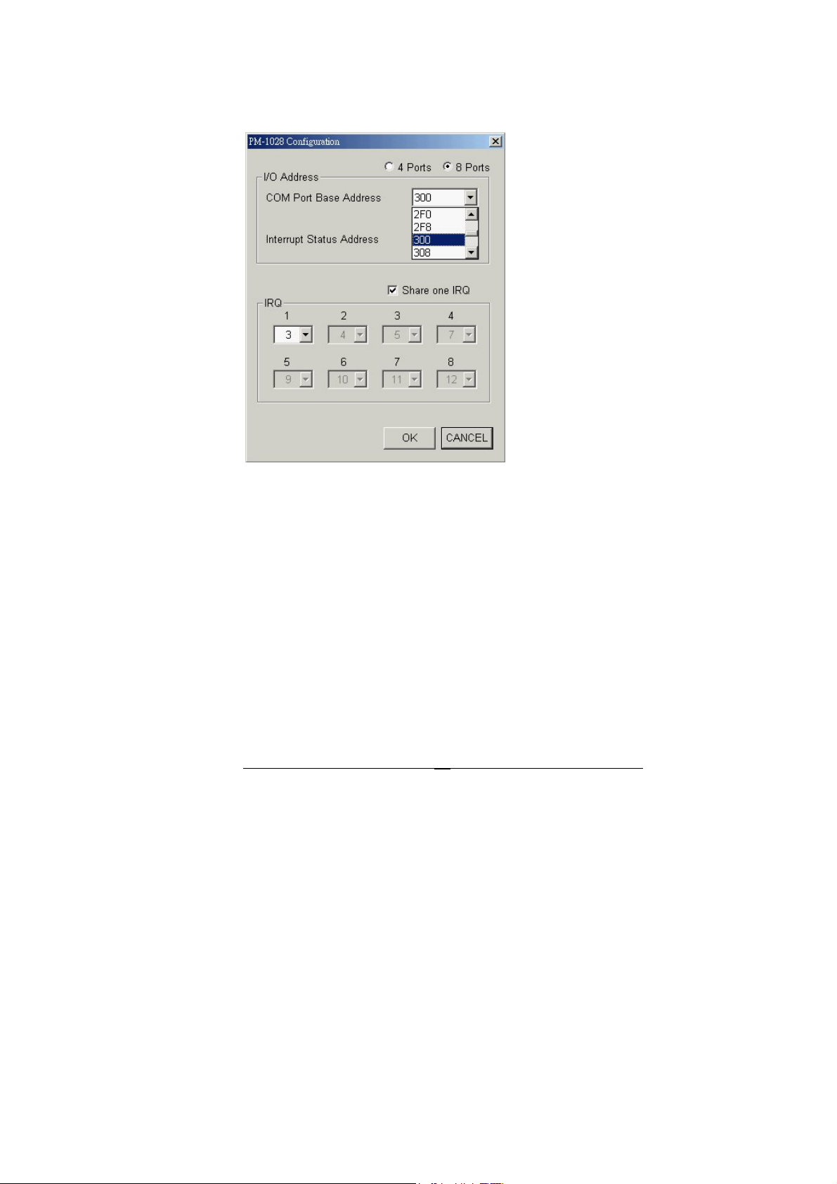
Click “8 Ports” for PM-1028-8 or “4 Ports” for PM-1028-4.
Select the “COM Port Base Address” and “ Interrupt Status
Address” options that match the jumper settings the PM-1028.
21
Page 22

Check “Share one IRQ” if you want to share one IRQ for all
ports, otherwise uncheck it and select different IRQ for each
port.
After you complete the resource settings, click “OK” to accept
the settings and restart the computer in the following window to
let the new settings take effect.
22
Page 23

After the computer restarts, you can use Device Manager to
check if all the PM-1028 ports were successfully added.
For Windows XP:
Go to Start -> Settings -> Control Panel -> System ->
Hardware -> Device Manager -> Ports and look for “Multiport
Communications Port”.
For Windows 2000:
Go to Start -> Settings -> Control Panel -> System ->
Hardware -> Device Manager -> Ports and look for “PM-1028
Multiport”.
23
Page 24

For Windows NT:
Go to Start -> Settings -> Control Panel -> Ports
NOTE: To change jumper settings after ports are installed and
listed in Device Manager, remove the PM-1028 ports from the
list of Device Manger and run PM-1028 Setup again.
24
Page 25

4.3 Uninstall PM-1028 Device Driver
To uninstall PM-1028 device driver, go to start -> Settings ->
Control Panel -> Add/Remove Programs.
Select “PM-1028 Multiport Driver” in the list of programs and
click “Change/Remove”. Follow the instructions on the screen
to complete the procedure.
25
Page 26

26
 Loading...