


International Electronics, Inc.
427 Turnpike Street
Canton, Massachusetts 02021
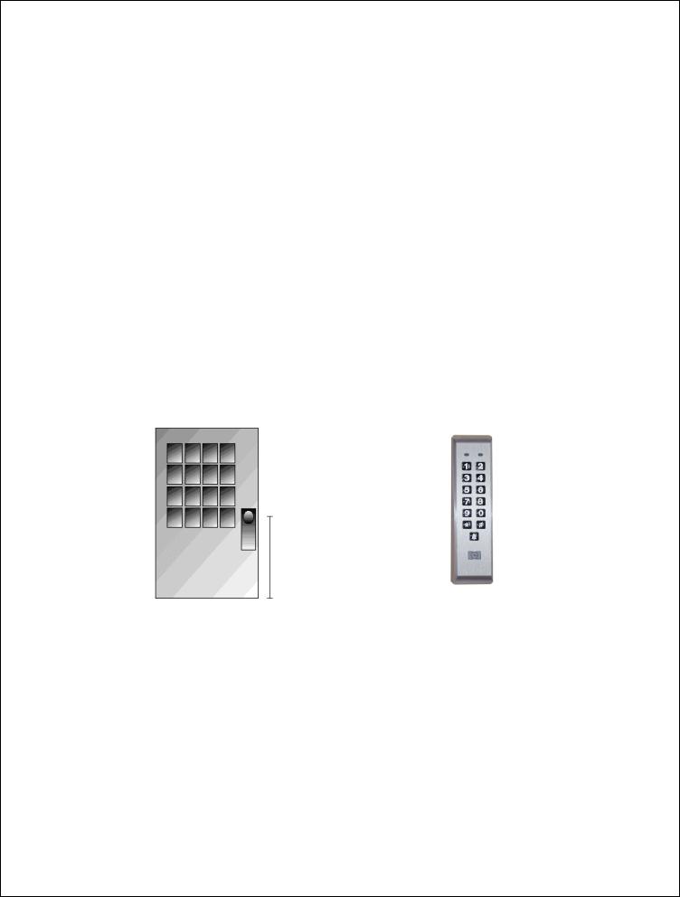
212iLM Mullion (ILLUMINATED WEATHER RESISTANT) Keypad
Stand Alone Keypad-Installation Manual
Features:
v120 User Capability
vIlluminated Hardened Keys
vProgrammable 00-99 Second Relay Activation Time
vRemote Trigger Input (REX)
vBell output (timed or continuous)
vDesigned for Heavy Traffic Application (greater than 1 million cycles)
vSurface Mount
vIndoor / outdoor Applications
vFully encapsulated
Installation:
qSection 1: Unpacking and checking the packing list
qSection 2: Mounting the 212iLM Mullion
qSection 3: Wiring the 212iLM Mullion
qSection 4: Power Up and System Defaults
qSection 5: Programming the 212iLM Mullion
qSection 6: Trouble Shooting
Page 1 of 17 |
6051344 Rev. 1.0 |
q Section 1: Unpacking and checking the packing list
Open the box, and inside you will find:
Keypad: (1) 212iLM Mullion keypad Harnesses: (1) 8 Conductor wire harness Wrenches: (1) Standard 5/64 allen wrench
Hardware: (1) Hardware Pack containing: (2) 8 x1¼” Panhead Slotted Machine Screw; (2) 8 x 1¼” Round Head Wood Screw; (2) 6-8 x ¾” Plastic Anchor, (1) 212iLM mounting template.
Literature: (1) 212 Standalone Mullion Instruction Manual
Please check the contents of this package and verify all components in the packing list are present. Taking this inventory will familiarize you with the components as well as ensure that you have a complete parts list.
Tools required:
You will need a drill, drill bits1/8, 3/16 & 5/16 (for the plastic anchors), wire strippers, regular & small flat blade screwdrivers, a marking pen or pencil, some heat shrinkable tubing (for the wire splices), a ruler or measuring tape, silicone to seal any holes and possibly some electrical tape to hold the wires together or the template in place.
qSection 2: Mounting the 212iLM Mullion
212iLM Mullion Dimensions: 6 ½”L x 1 ¾”W x 1 1/8”D
Select the appropriate location for the 212iLM Mullion. Mounting height is the same for an electrical switch, 48" on center. The 212iLM Mullion should be Surface Mounted with a 1/4” hole for the wires centered approximately 5/8 of an inch underneath the center of bottom mounting hole (refer to the included mounting template).
Suggested mounting height is 48”
q Section 3: Wiring
Electrical Specifications:
Operating Voltages: |
Max Current Draw @ allowed voltages: |
Temperature Tolerance: |
12-24V-AC/DC only |
53mA@12V, 72mA@24V; 94mA@12VAC, |
Standard, -20° to 130°F. |
for input voltage. |
103mA@16VAC, 108mA@24VAC |
|
*Tech noteAlthough the 212iLM will work with AC or DC voltage, it is recommended to use a filtered and regulated power supply for it’s ability to maintain voltage and reduce the possibility of voltage spikes.
Page 2 of 17 |
6051344 Rev. 1.0 |

1.Attach the 8-conductor wire harness to the plug in connector on the back of the 212iLM Mullion.
2.Next you will need to attach the relay wires (white/yellow, blue, and brown) to the wire run that is connected to the locking device.
3.The Red and Black wires are connected to the power supply last, BEFORE the power is turned on. Connect positive of the supply to the Red wire and negative to the Black wire.
|
212iLM Mullion: Wire Colors and Designations: |
1---- |
----2 |
|||||
Pin |
Wire Color |
Signal Name |
Pin |
Wire Color |
Signal Name |
3---- |
----4 |
|
1 |
Red |
V in(+) |
5 |
Blue |
Main Relay Common |
|||
5---- |
----6 |
|||||||
2 |
Black |
V in(-) |
6 |
Brown |
Main Relay NO |
|||
3 |
White/Black |
REX |
7 |
White |
Bell Relay Contact (A) |
7---- |
----8 |
|
4 |
White/Yellow |
Main Relay NC |
8 |
White |
Bell Relay Contact (B) |
|||
|
|
|||||||
Wiring to a Magnetic Lock: (see below)
The 212iLM Mullion is equipped with a Form C, Dry contact relay. This means that there is no voltage running through the relay (until you supply the common leg of the relay with voltage).
Situation 1:
If you are using a common power supply with the 212iLM Mullion and the Magnetic Lock, (that is to say if you have only one power supply for both the 212iLM Mullion and the lock device), you need to run voltage through the common (blue) wire on the 8 conductor wire harness of the 212iLM Mullion
Step 1: Splice together the Blue (common) wire from the 212iLM Mullion harness to the Red wire on the 212iLM Mullion harness and to positive voltage coming from the power supply.
Step 2: Connect the White /Yellow wire (normally closed) from the 212iLM Mullion harness to the Positive connection on the Magnetic Lock.
Step 3: Splice together the Black wire on the 212iLM Mullion to the Negative connection on the Magnetic Lock harness and to negative voltage coming from the power supply.
Example of Wiring to a Electro-Magnetic Lock Using a COMMON Power Supply:
White/Yellow = Normally Closed
212iLM |
|
Wire |
|
Harness |
Blue =Common |
To Power Supply V+ |
Red |
|
|
To Power Supply V- |
Black |
|
_ +
Situation 2:
If you are using a separate power supply with the 212iLM Mullion and the Magnetic Lock, you need to run voltage from the positive of the power supply to the common (blue) wire on the 8 conductor wire harness of the 212iLM.
Step 1: Connect the Positive (red) wire on the 212iLM Mullion harness to Positive voltage coming from the 212iLM power supply.
Step 2: Connect the Negative voltage wire on the 212iLM power supply to the Negative (black) voltage wire on the 212iLM
Step 3: Connect the Blue (common) wire from the 212iLM harness to the Positive voltage on the lock power supply
Step 4: Connect the Negative voltage coming from the lock power supply to the Negative connection on the Magnetic lock.
Step 5: Connect the White/Yellow (normally closed) on the harness to the positive connection on Magnetic Lock.
Page 3 of 17 |
6051344 Rev. 1.0 |

Example of Wiring to a Electro-Magnetic Lock Using a SEPARATE Power Supply:
212iLM |
|
Blue =Common |
White/Yellow = Normally Closed |
|
|
|
_ |
|
|
Wire |
|
|
+ |
|
Harness |
|
|
|
|
To 212iLM |
V+ |
Red |
|
|
|
|
|
||
Power Supply |
V- |
Black |
|
|
|
|
|
|
|
To Lock |
V+ |
|
|
|
Power Supply V- |
|
|
|
|
Wiring to an Electric Strike: (see below)
The 212iLM Mullion is equipped with a Form C, Dry contact relay on board. This means that there is no voltage running through the relay (until you supply the common leg of the relay with voltage).
Situation 1:
If you are using a common power supply with the 212iLM Mullion and the Electric Strike, (that is to say if you have only one power supply for both the 212iLM Mullion and the lock device), you need to run voltage through the common (blue) wire on the 8 conductor wire harness of the 212iLM Mullion
Step 1: Splice together the Blue (common) Relay wire from the 212iLM Mullion harness to the Red wire on the 212iLM Mullion harness and to positive voltage coming from the power supply.
Step 2: Connect the Brown (normally open) wire from the 212iLM Mullion harness to the Positive voltage connection on the Electric door strike.
Step 3: Splice together the Black wire on the 212iLM Mullion to the Negative connection on the Electric door strike harness and to negative voltage coming from the power supply.
Example of Wiring to an Electric Strike Using a COMMON Power Supply:
212iLM |
Blue = Common |
||
Wire |
|||
|
|
||
Harness |
|
|
|
|
Brown = Normally |
||
|
|
open |
|
|
|
||
|
To Power Supply V+ |
Red |
|
|
|
||
|
To Power Supply V- |
Black |
|
|
|
||
|
|
|
|
+
_
Page 4 of 17 |
6051344 Rev. 1.0 |

Situation 2:
If you are using a separate power supply with the 212iLM Mullion and the Electric Strike, you need to run voltage from the positive of the power supply to the Brown (normally open) wire on the 8 conductor wire harness of the 212iLM.
Step 1: Connect the Positive (red) wire on the 212iLM Mullion harness to Positive voltage coming from the 212iLM power supply.
Step 2: Connect the Negative voltage wire on the 212iLM power supply to the Negative (black) voltage wire on the 212iLM power supply.
Step 3: Connect the Brown (normally open) on the harness to the positive connection on Electric Strike. Step 4: Connect the Blue (common) wire from the 212iLM harness to the Positive voltage on the lock
power supply.
Step 5: Connect the Negative voltage coming from the lock power supply to the Negative connection on the Electric Strike.
Example of Wiring to an Electric Strike Using a SEPARATE Power Supply:
212iLM |
|
Blue = Common |
Wire |
|
|
Harness |
|
Brown = Normally |
|
|
open |
To 212iLM |
V+ |
Red |
|
||
Power Supply |
V- |
Black |
|
|
|
To Lock |
V+ |
|
Power Supply V- |
|
|
+
_
Shunting a Normally Closed Zone: (see below)
Step 1: Connect the Blue (Common) Relay wire from the 212iLM Mullion harness to the Common connection on the door position switch.
Step 2: Connect the Brown (Normally Open) Relay wire from the 212iLM Mullion harness to the Normally closed connection on the Door position switch.
Example of Shunting a Normally Closed Zone
To Power Supply V-
Black
To Power Supply V+
Red
Blue = Common
212iLM Wire Harness
Brown = Normally open
Page 5 of 17 |
6051344 Rev. 1.0 |

Wiring to a Request to Exit (Push to release):
The 212iLM Mullion keypad may be wired to accept an input from a remote-switching device. This is a momentary input that will engage the main relay for the same amount of time that the master code is programmed with. This input requires a normally open, momentary closure between the White with a Black trace wire and the Black wire. The only time the REX won't follow the main relay time is if the Master code has been programmed to latch the main relay. In this case, the REX will operate with the default time of 5 seconds. You may wire in several devices parallel to release the door from different locations but they must all be normally open devices. There is no programming required for this option.
The 212 iLM needs normally open DRY contacts to operate the relay with the REX input. If your remote exit device sends voltage when it is pressed, you MUST connect an external relay to the wires coming from the REX, then connect the 212iLM Mullion REX connections to the common and the normally open connections on the external relay.
Step 1: Connect the White with Black trace wire on the 212iLM Mullion harness to the common connection on the REX device.
Step 2: Splice a wire to the Black (negative) wire on the 212iLM Mullion harness and connect to the Normally Open connection on the REX device.
Example of wiring to an IEI request to exit device (part # EZ-REX):
To Power Supply V+
|
Red |
Black = Negative |
To Power Supply V- |
|
|
|
|
|
212iLM |
|
|
Wire |
|
White/Black = Normally |
Harness |
|
|
|
Open REX Input |
|
|
|
|
|
|
|
Wiring the Bell Button:
There are 2 white wires on the 8 conductor harness, an A (common) and a B (normally open) for the bell button. This is a dry contact, normally open form A relay. Connect positive (from power) to common (A) of the 212iLM wiring harness. Connect normally open (B) of the 212iLM harness to positive terminal of bell or speaker. Then connect the negative of bell or speaker to the negative of the power supply.
Step 1: Connect the Black (Negative) wire from the 212iLM Mullion harness to the Negative connection on the doorbell speaker and splice it into the negative wire from the power supply.
Step 2: Connect the White (Common-A) wire from the 212iLM Mullion harness to the Positive connection on the doorbell speaker.
Step 3: Connect the White (Common-B) wire from the 212iLM Mullion harness to the Positive wire from the power supply.
Page 6 of 17 |
6051344 Rev. 1.0 |
 Loading...