

Page 1
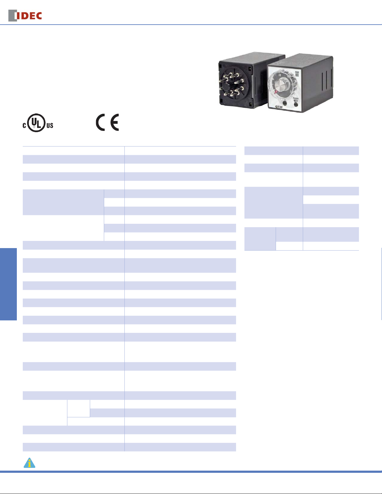
GT3W Series
GT3W Series — Dual Time Range Timers
Key features of the GT3W series include:
Sequential start, sequential interval, on-delay, recycler,
•
and interval ON timing functions
2 time settings in one timer
•
8 selectable operation modes on each model
•
Mountable in sockets or fl ush panel
•
Switches & Pilot LightsDisplay LightsRelays & SocketsTimersTerminal Blocks
Power and output status indicating LEDs
•
Time ranges up to 300 hours
•
UL, c-UL Listed
File No. E55996
General Specifi cations Contact Ratings
Operation System Solid state CMOS Circuit Allowable Contact Power 960VA/120W
Operation Type Multi-Mode
Time Range 1: 0.1sec to 6 hours, 3: 0.1sec to 300 hours
Pollution Degree 2 (IE60664-1)
Over Voltage Category III (IE60664-1)
Rated Operational Voltage
Voltage Tolerance
Disengaging Value of Input Voltage Rated Voltage x10% minimum
Range of Ambient Operating Temperature -10 to +50ºC (without freezing)
Range of Ambient Storage
and Transport Temperature
Range of Relative Humidity 35 to 85%RH (without condensation)
Atmospheric Pressure 80kPa to 110kPa (Operating), 70kPa to 110kPa (Transport)
Reset Time 60msec maximum
Repeat Error ±0.2%, ±10msec*
Voltage Error ±0.2%, ±10msec*
Temperature Error ±0.6%, ±10msec*
Setting Error ±10% maximum
Insulation Resistance 100MΩ minimum (500V DC)
Dielectric Strength
Vibration Resistance 10 to 55Hz amplitude 0.75mm2 hours in each of 3 axes
Shock Resistance
Degree of Protection IP40 (enclosure), IP20 (socket) (IEC60529)
Power Consumption
(Approx.)
Mounting Position Free
Dimensions 40Hx 36W x 70 mm
Circuit Breakers
Weight (Approx.) 72g
* For the value of the error against a preset time, whichever the largest applies.
AF20 100-240V AC(50/60Hz)
AD24 24V AC(50/60Hz)/24V DC
D12 12V DC
AF20 85-264V AC(50/60Hz)
AD24 20.4-26.4V AC(50/60Hz)/21.6-26.4V DC
D12 10.8-13.2V DC
AF20
100V AC/60Hz 2.3VA
200V AC/60Hz 4.6VA
AD24 (AC/DC) 1.8VA/0.9W
-30 to +75ºC (without freezing)
Between power and output terminals: 2000V AC, 1 minute
Between contacts of different poles: 2000V AC, 1 minute
Between contacts of the same pole:750V AC, 1 minute
Operating extremes: 98m/sec2 (approx.10G)
Damage limits: 490m/sec2 (approx. 50G)
3 times in each of 3 axes
Allowable Voltage 250V AC/150V DC
Allowable Current 5A
Maximum permissible
operating frequency
Rated Load
Conditional Short Circuit Fuse 5A, 250V
Life
Electrical
Mechanical 20,000,000 op. minimum
Timers
1800 cycles per hour
1/8HP, 240V AC
3A, 240V AC (Resistive)
5A, 120V AC/30V DC
(Resistive)
100,000 op. minimum
(Resistive)
834
www.idec.com
Page 2
Timers
GT3W Series
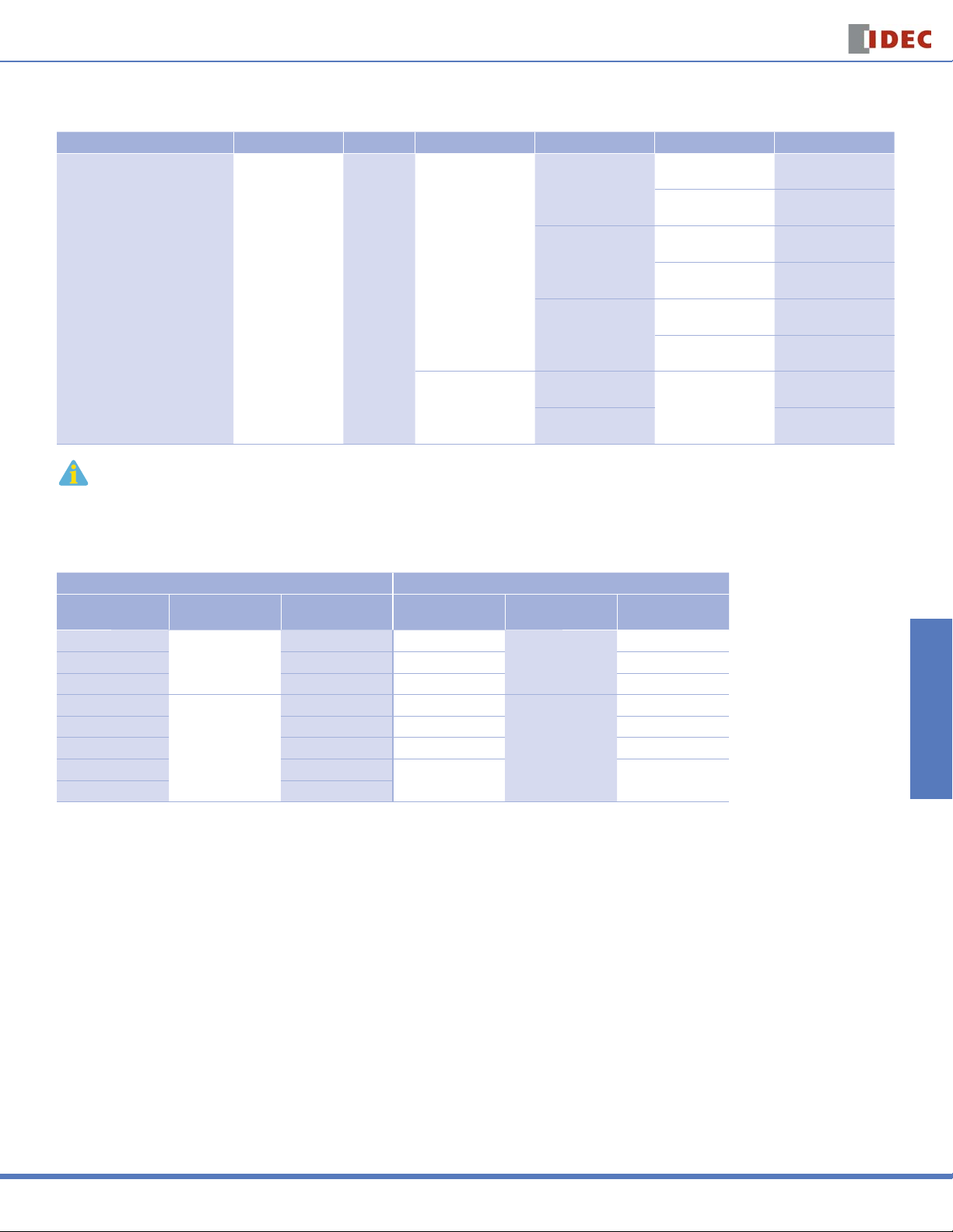
Part Number List
Part Numbers
Mode of Operation Output Contact Time Range* Rated Voltage Pin Confi guration New Part Numbers
8 pin GT3W-A11AF20N
11 pin GT3W-A11EAF20N
8 pin GT3W-A11AD24N
11 pin GT3W-A11EAD24N
8 pin GT3W-A11D12N
11 pin GT3W-A11ED12N
8 pin
A: Sequential Start
B: On-delay with course and fi ne
C: Recycler and instaneous
D: Recycler outputs (OFF Start)
E: Recycler outputs (ON Start)
F: Interval ON
G: Interval ON Delay
H: Sequential
Interval
1. For timing diagrams and schematics, see page 836.
2. For socket and accessory part number information, see page 838.
3. 8- and 11-pin models differ only in the number of pins (extra pins are not used).
4. For the timing diagram overview, see page 794.
5. *For details on setting time ranges, see the instructions on page 837.
3A, 240V AC
5A, 120V AC/30V DC
(Resistive Load)
Delayed
SPDT
+
Delayed
SPDT
1: 0.1sec - 6 hours
*(See Time Range Settings for details.)
3: 0.1sec - 300 hours
100 to 240V AC
(50/60Hz)
24V AC/DC
12V DC
100 to 240V AC
(50/60Hz)
24V AC/DC GT3W-A33AD24N
Switches & Pilot Lights Display Lights Relays & Sockets Timers Terminal Blocks
GT3W-A33AF20N
Time Range Table
Time Range Code: 1 Time Range Code: 3
Time Range
Selector
1S
10S 0.3 sec - 10 sec 1M 3 sec - 3 min
10M 15 sec - 10 min 1H 3 min - 3 hours
1S
10S 1 sec - 60 sec 1M 36 sec - 30 min
1M 6 sec - 6 min 1H 36min - 30 hours
10M 1 min - 60 min
1H 6 min - 6 hours
Scale Time Range
0.1 sec - 1 sec 1S
0-1
0.1 sec - 6 sec 1S
0 - 6
Time Range
Selector
10H 6 hours - 300 hours
Scale Time Range
0 - 3
0 - 30
0.1 sec - 3 sec
0.6 sec - 30 sec
USA: 800-262-IDEC Canada: 888-317-IDEC
Circuit Breakers
835
Page 3

GT3W Series
Timers
Timing Diagrams/Schematics
Switches & Pilot LightsDisplay LightsRelays & SocketsTimersTerminal Blocks
8-Pin 11-Pin
m
n
l
k
j
q
o
p
(+)(-)
m
l
k
n
j
o
p
q
r
s
(+)(-)
POWER POWER
Mode Operation Chart Mode Operation Chart
Terminal
Item
No.
Power
2-7
1-4
Delayed
(NC)
Contact
1-3
Ry1
(NO)
5-8
Delayed
(NC)
Contact
6-8
Ry2
(NO)
Indicator
Set Time
Item
Power
Delayed
Contact
Ry1
Delayed
Contact
Ry2
Indicator
Set Time
Item
Power
Delayed
Contact
Ry1
Delayed
Contact
Ry2
Indicator
Set Time
Item
Power
Delayed
Contact
Ry1
Delayed
Contact
Ry2
Indicator
Set Time
OUT1
OUT2
Terminal
No.
2-7
1-4
(NC)
1-3
(NO)
5-8
(NC)
6-8
(NO)
OUT1
OUT2
Terminal
No.
2-7
1-4
(NC)
1-3
(NO)
5-8
(NC)
6-8
(NO)
OUT1
OUT2
Terminal
No.
2-7
1-4
(NC)
1-3
(NO)
5-8
(NC)
6-8
(NO)
OUT1
OUT2
T1
T1 T2
T1 T2
A: Sequential Start
B: On-delay with course and fi ne
C: Recycler and instantaneous
D: Recycler outputs (OFF Start)
Operation
T2
Operation
T1 T2
Operation
Operation
Description
ON after T1
ON after T1 + T2
Description
ON after T1 + T2
ON after T1 + T2
Description
Instantaneous ON
OFF during T1
ON during T2
Description
OFF during T1
ON during T2
OFF during T1
ON during T2
E: Recycler outputs (ON Start)
F: Interval ON
G: Interval ON Delay
H: Sequential Interval
Item
Power
Delayed
Contact
Ry1
Delayed
Contact
Ry2
Indicator
Set Time
Item
Power
Delayed
Contact
Ry1
Delayed
Contact
Ry2
Indicator
Set Time
Item
Power
Delayed
Contact
Ry1
Delayed
Contact
Ry2
Indicator
Set Time
Item
Power
Delayed
Contact
Ry1
Delayed
Contact
Ry2
Indicator
Set Time
Terminal
No.
2-7
1-4
(NC)
1-3
(NO)
5-8
(NC)
6-8
(NO)
OUT1
OUT2
Terminal
No.
2-7
1-4
(NC)
1-3
(NO)
5-8
(NC)
6-8
(NO)
OUT1
OUT2
Terminal
No.
2-7
1-4
(NC)
1-3
(NO)
5-8
(NC)
6-8
(NO)
OUT1
OUT2
Terminal
No.
2-7
1-4
(NC)
1-3
(NO)
5-8
(NC)
6-8
(NO)
OUT1
OUT2
T1
T1
T1 T2
T1 T2
Operation
T2
Operation
T2
Operation
Operation
Description
ON during T1
OFF during T2
ON during T1
OFF during T2
Description
ON during T1
ON after T1,
during T2
Description
ON during T1
ON after T1 + T2
Description
ON during T1 + T2
ON after T1,
during T2
Circuit Breakers
836
www.idec.com
Page 4

Timers
GT3W Series
Instructions: Setting GT3W Timer
T2 Time Range Selector
Operation Mode Selector
T1 Time Range Selector
Special expertise is required to use Electronic Timers.
•
All Electronic Timer modules are manufactured under IDEC’s rigorous quality
control system, but users must add a backup or fail safe provision to the
control system when using the Electronic Timer in applications where heavy
damage or personal injury may occur should the Electronic Timer fail.
•
Install the Electronic Timer according to instructions described in this catalog.
•
Make sure that the operating conditions are as described in the specifi cations. If you are uncertain about the specifi cations, contact IDEC in advance.
•
In these directions, safety precautions are categorized in order of importance
to Warning and Caution.
Warning
Warning notices are used to emphasize that improper operation may cause sever
personal injury or death.
Turn power off to the Electronic timer before starting installation, removal,
•
Wiring, maintenance, and inspection on the Electronic Timer.
T2 Setting Knob
T1 Setting Knob
Safety Precautions
1. The switches should be securely turned using a fl at screwdriver 4mm
wide (maximum). Note that incorrect setting may cause malfunction.
The switches, which do not turn infi nitely, should not be turned beyond
their limits.
2. Since changing the setting during timer operation my cause malfunction,
turn power off before changing.
Caution
Caution notices are used where inattention might cause personal injury or damage to equipment.
The Electronic Timer is designed for installation in equipment. Do not install
•
the Electronic Timer outside equipment.
Install the Electronic Timer in environments described in the specifi cations. If
•
the Electronic Timer is used in places where it will be subjected to high-temperature, high-humidity, condensation, corrosive gases, excessive vibrations,
or excessive shocks, then electrical shocks, fi re hazard, or malfunction could
result.
Use an IEC60127-approved fuse and circuit breaker on the power and output
•
line outside the Electronic Timer.
Do not disassemble, repair, or modify the Electronic Timer.
•
When disposing of the Electronic Timer, do so as industrial waste.
•
Switches & Pilot Lights Display Lights Relays & Sockets Timers Terminal Blocks
Failure to turn power off may cause electrical shocks or fi re hazard.
•
Emergency stop and interlocking circuits must be confi gured outside the
•
Electronic timer. If such a circuit is confi gured inside the Electronic Timer,
failure of the Electronic timer may cause malfunction of the control system, or
an accident.
USA: 800-262-IDEC Canada: 888-317-IDEC
Circuit Breakers
837
 Loading...