

Page 1
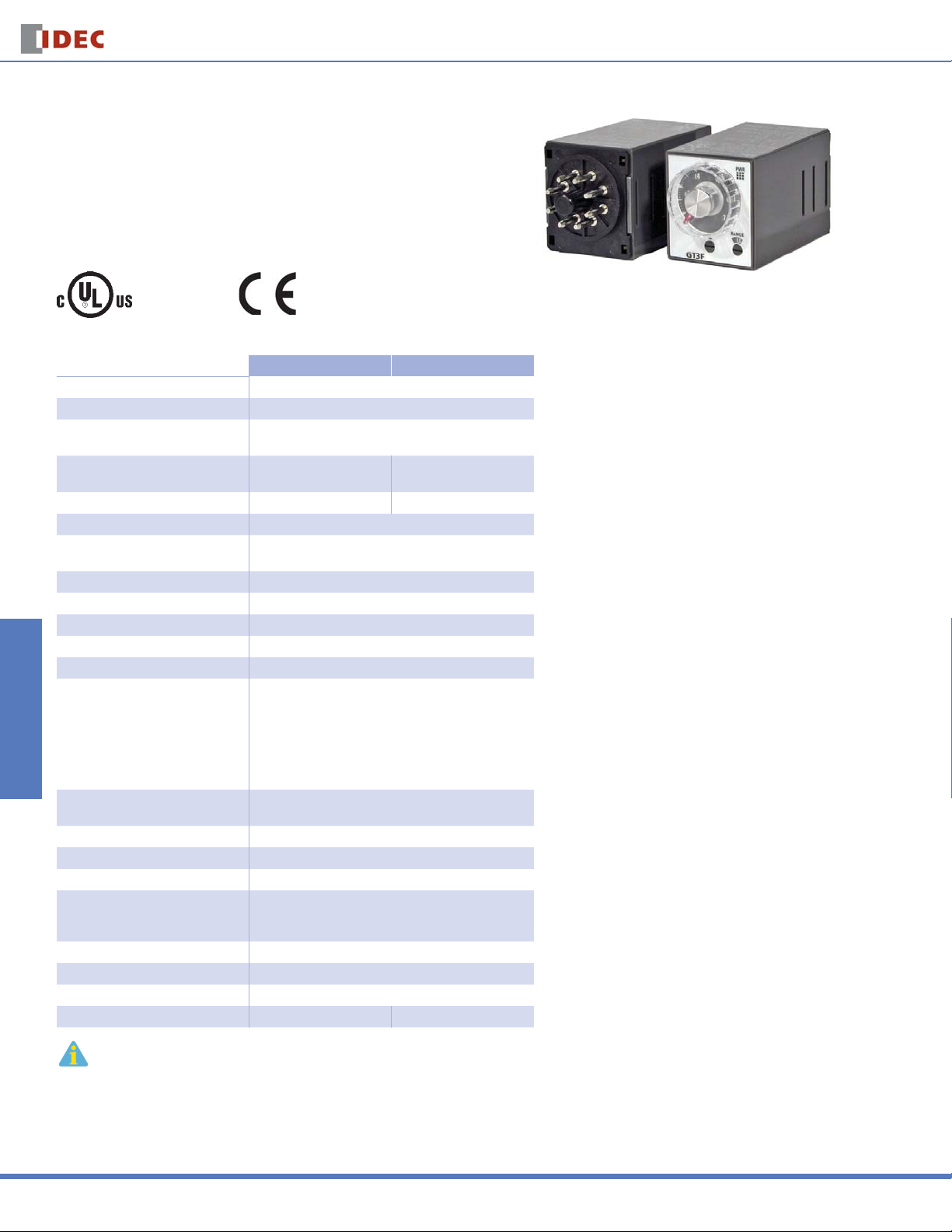
GT3F Series
GT3F Series — True OFF Delay Timers
Key features of the GT3F series include:
“True” power OFF-delay up to 10 minutes
•
No external control switch necessary
•
Available with reset inputs
•
Mountable in sockets or fl ush panel
•
Switches & Pilot LightsDisplay LightsRelays & SocketsTimersTerminal Blocks
UL, c-UL Listed
File No. E55996
Specifi cations
Operation True power OFF-delay
Time Range 0.1 seconds to 600 seconds
Rated Voltage
Contact Rating
Contact Form SPDT DPDT
Minimum Power Application Time 1 second
Voltage Tolerance
Repeat Error ±0.2%, ±10 msec
Voltage Error ±0.2%, ±10 msec
Temperature Error ±0.2%, ±10 msec
Setting Error ±10% maximum
Insulation Resistance 100MW minimum
Dielectric Strength
Power Consumption
Mechanical Life 20,000,000 operations minimum
Electrical Life 100,000 operations minimum
Vibration Resistance 100m/sec2 (approximate 10G)
Shock Resistance
Operating Temperature –10 to +50°C
Storage Temperature –30 to +80°C
Operating Humidity 45 to 85% RH
Weight (approximate) 77g 79g
1. An inrush current fl ows during the minimum power application time. AF20: approximate 0.4A,
AD24: approximate 1.2A
2. GT3F does not read the preset time range shown on the knob after power is turned off. Note that minimizing
the preset time, by turning the knob to zero, does not shorten the delay time after power is removed.
Circuit Breakers
GT3F-1 GT3F-2
100 to 240V AC, 50/60Hz
24V AC/DC
250V AC/30V DC, 5A
(resistive load)
AF20: 100 to 240V AC
AD24: 21.6 to 26.4VDC, 20.4 to 26.4VAC
Between power and output terminals:
2,000V AC, 1 minute (SPDT)
1,500V AC, 1 minute (DPDT)
Between contacts on different poles:
1,000V AC, 1 minute (DPDT)
Between contacts of the same pole:
750V AC, 1 minute
AF20: 3.7VA (200V AC, 60Hz)
AD24: 0.8W (DC), 1.2VA (AC)
Operating extremes:
100 m/sec2 (approximate 10G)
Damage limits: 500 m/sec
250V AC/30V DC, 3A
(resistive load)
2
(approximate 50G)
Timers
826
www.idec.com
Page 2
Timers
GT3F Series
GT3F
Mode of
Operation
Power OFF-delay
Optional reset input resets the contact to the OFF state before time out.
Rated
Voltage Code
AF20: 100 to
240VAC (50/60Hz)
AD24: 24V AC/DC
Time Range Output Contact Optional Input
0.1 seconds to
600 seconds
GT3F-1 Timing Diagrams
GT3F-1 (8-pin) GT3F-1E (11-pin)
Part Numbering List
Complete Part Number
8-Pin 11-Pin
250V AC, 5A,
30V DC, 5A (resistive load) GT3F-1AD24 GT3F-1EAD24
250V AC, 3A,
30V DC, 3A (resistive load) GT3F-2AD24 GT3F-2EAD24
Delayed SPDT Reset
Delayed DPDT
None (8p)
Reset (11p)
GT3F-1AF20 GT3F-1EAF20
GT3F-2AF20 GT3F-2EAF20
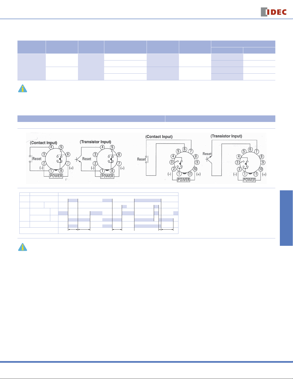
Timing Diagrams/Schematics
Delayed SPDT Output, with Reset Input
Switches & Pilot Lights Display Lights Relays & Sockets Timers Terminal Blocks
Item Terminal Number Operation
Power
Reset
Input
Delayed
Contact
Indicator POWER
Set Time
2 - 7 (8p)
2 - 10 (11p)
1 - 4 (8p)
6 - 7 (11p)
T = Set time
Ta = Shorter than set time
Ts = 1 Second
Tr = Minimum Power Application Time
GT3F-1: 1 Second
5 - 8 (8p)
1 - 4 (11p)
6 - 8 (8p)
1 - 3 (11p)
ON or L
(NC)
(NO)
Tr T Ta Ts T
1. For time ranges, see page 829.
2. For sockets and accessory part numbers, see page 838.
3. When power is applied, the NO output contact closes. When power is removed, the timing period
begins. When time has elapsed, the NO contact opens.
4. For the timing diagram overview, see page 794.
Circuit Breakers
USA: 800-262-IDEC Canada: 888-317-IDEC
827
Page 3

GT3F Series
GT3F-2 Timing Diagrams
Timers
GT3F-2 (8-pin) GT3F-2E (11-pin)
Delayed DPDT Output
Switches & Pilot LightsDisplay LightsRelays & SocketsTimersTerminal Blocks
8-Pin Type
11-Pin Type
(Contact Input)
m
n
l
k
j
POWER
Item Terminal Number Operation
Power 2 - 7
Delayed
Contact
Indicator POWER
Set Time
Item Terminal Number Operation
Power 2 - 10
Reset
6 - 7 (11p) ON or L
Input
Delayed
Contact
Indicator POWER
Set Time
1 - 4
5 - 8
1 - 3
6 - 8
1 - 4
8 - 11
1 - 3
9 - 11
q
o
p
Reset
(+)(-)
(NC)
(NO)
TTrT
(NC)
(NO)
Tr T Ta Ts T
m
l
k
n
j
POWER
o
p
q
s
r
(Transistor Input)
Reset
(+)(-)
m
l
k
n
j
POWER
o
p
q
s
r
(+)(-)
When power is applied, the NO contact closes. When power is removed, the timing period begins. When time has elapsed, the NO contact opens. Optional reset
input will return contacts to original state before time elapses.
T = Set time
Ta = Shorter than set time
Ts = 1 Second
Tr = Minimum Power Application Time
GT3F-1: 1 Second
Item Terminal Number Operation
Power 2 - 10
Reset
6 - 7 (11p) ON or L
Input
Delayed
Contact
Indicator POWER
Set Time
1 - 4
8 - 11
1 - 3
9 - 11
(NC)
(NO)
Tr T Ta Ts T
Circuit Breakers
828
www.idec.com
Page 4

Timers
GT3F Series
Instructions: Setting GT3F Series Timers
POWER Indicator
l Setting Knob
j Dial Selector
0-1, 0-3, 0-6, 0-18, 0-60
Step 1 Desired Operation Selection Remarks
Select a time
range that
contains the
desired period
of time.
Base Time Ranges
0.1s to 1s 0 to 1
0.1s to 6s 0 to 6
0.1s to 10s 0 to 1
0.3s to 30 0 to 3
0.6s to 60 0 to 6
1.8s to 180s 0 to 18
6s to 600s 0 to 60
j Dial Selector k Time Range Selector
1s0.1s to 3s 0 to 3
Time range can be selected from 1S and 10S using a fl at screwdriver and fi ve
different dials of 0 to 1, 0 to 3, 0 to 6, 0 to 18, and 0 to 60 are displayed in the six
windows by turning the Dial Selector, allowing for selecting the best suited scale.
Note that the switch does not turn infi nitely.
10s
Step 2 Remarks
Setting Examples:
k Time Range Selector
1S, 10S
Switches & Pilot Lights Display Lights Relays & Sockets Timers Terminal Blocks
The set time is selected by turning the l Setting Knob.
1. When the Setting Knob l is set at 2.5, with Dial Selector j 0 to 3 and Time
Range Selector k 1S selected, then the set time is 2.5 seconds.
2. When the Setting Knob l is set at 5.0,
with Dial Selector j 0 to 60 and Time Range Selector k 10S selected, then the
set time is 500 seconds.
Circuit Breakers
USA: 800-262-IDEC Canada: 888-317-IDEC
829
Page 5

GT3F Series
Instructions: Wiring Inputs
Inputs of GT3F
To avoid electric shock, do not touch the input signal terminal during power voltage application.
Never apply the input signals to two or more GT3F timers using the same contact or transistor.
[Incorrect]
Input
Contact or Transistor
Switches & Pilot LightsDisplay LightsRelays & SocketsTimersTerminal Blocks
In a transistor circuit for controlling input signals, with its primary and secondary power circuits isolated, do not ground the secondary circuit.
On the GT3F timers, connect the input signals to terminal No.1 and 4 only on the 8-pin type; connect the input signals to terminal No. 6 and 7 only on the 11-pin type.
Never apply voltage to other terminals; otherwise, the internal circuit may be damaged.
GT3 Series
Timer
Input
Terminal
10
2
Input
Terminal
10
2
GT3 Series
Timer
Input
Terminal
Circuit
Rectifier
Circuit
Insulating Transformer
Power
Power
[correct]
Input
Terminal
10
2
Input
Terminal
10
2
Power
Timers
Input signal lines must be made as short as possible and installed away from power cables and power lines. Use shielded wires or a separate conduit for input wiring.
The GT3F, consisting of a high-impedance circuit, may not be reset due to the infl uence of an inductive voltage or residual voltage caused by a leakage current. If not
reset, connect an RC fi lter or bleeder resistor between power terminals so that the voltage between power terminals can be reduced to less than 15% of the rated
voltage.
Circuit Breakers
830
www.idec.com
 Loading...