

Page 1
Timers
GT3D Series
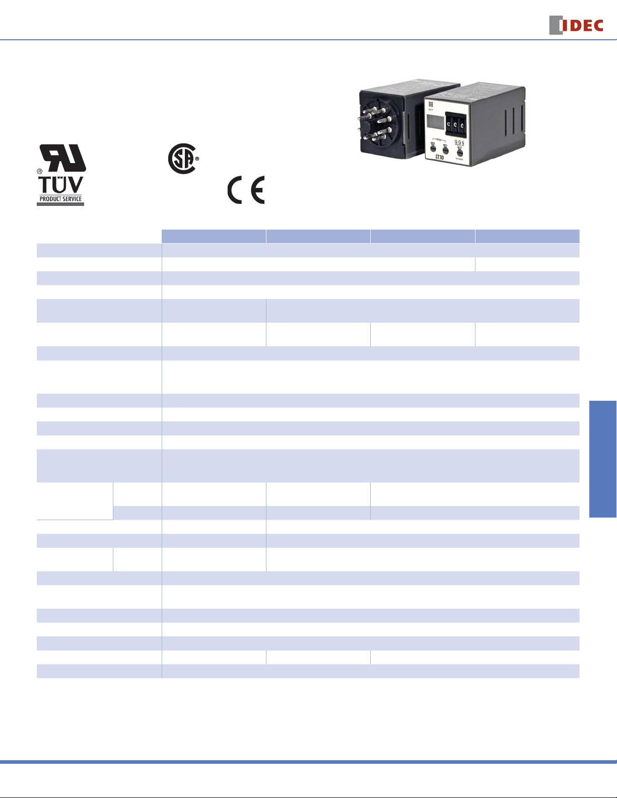
GT3D — Digital Timers
Key features of the GT3D series include:
Precise time setting using digital thumbwheel switches
•
Elapsed or time remaining LCD display
•
6 time ranges, 16 timing functions
•
Time delays up to 99.9 hours
•
CSA Certifi ed
UL Recognized
File No. E55996
Cert. No. BL9801133323911 (LVD)
Cert. No. E9971113332388 (EMC)
Specifi cations
Operation System Solid state CMOS circuitry
Operation Multi-mode Multi-mode one-shot output
Time Range 0.01s to 99.9 hours
Rated Voltage 100 to 240V AC (50/60Hz), 24V AC (50/60Hz)/24V DC
Contact Ratings
Contact Form
Minimum Applicable Load 5V, 10mA (reference value)
Voltage Tolerance
Error ±0.3% ±50ms (voltage, repeat, and temperature)
Setting Error ±0.5% ±50ms
Reset Time 60ms maximum
Insulation Resistance 100MΩ minimum
Dielectric Strength
Power Consumption
(approximate)
Mechanical Life 10,000,000 operations minimum 5,000,000 operations minimum
Electrical Life (at rated load) 50,000 operations minimum 100,000 operations minimum
Outputs Relay
Vibration Resistance 100N (approximate 10G)
Shock Resistance
Operating Temperature –10 to +50°C
Storage Temperature –30 to +80°C
Operating Humidity 45 to 85% RH
Weight (approximate) 70g 75g 76g
Housing Color Gray
AF20 11.8VA 11.6VA
AD24 AC/DC 1VA/0.8W 2.1VA/0.9W 2.1VA /0.9W
File No. LR58183
File No. LR96764
File No. LR83814
GT3D-2 GT3D-3 GT3D-4 GT3D-8
125V AC/250V AC, 3A;
30V DC/1A (resistive load)
Delayed SPDT +
instantaneous SPDT
250V AC, 3A, 30V DC, 1A
(resistive load)
125V AC/250V AC, 5A;
30V DC/5A (resistive load)
Delayed DPDT Delayed DPDT Delayed DPDT
AF20 (100–240V AC): 85 to 264V AC
AD24 (AC): 20.4 to 26.4V AC
AD24 (DC): 21.6 to 26.4V DC
Between power and output terminals: 2,000V AC, 1 minute
Between contacts of different poles: 2,000V AC, 1 minute
Between contacts of the same pole: 750V AC, 1 minute
3.7VA (100V AC, 60Hz)
11.6VA (200V AC, 60Hz)
240V AC/, 24V DC, 5A
(resistive load)
Operating extremes: 100N (approximate 10G)
Damage limits: 500N (approximate 50G)
Switches & Pilot Lights Display Lights Relays & Sockets Timers Terminal Blocks
Circuit Breakers
USA: 800-262-IDEC Canada: 888-317-IDEC
813
Page 2
GT3D Series
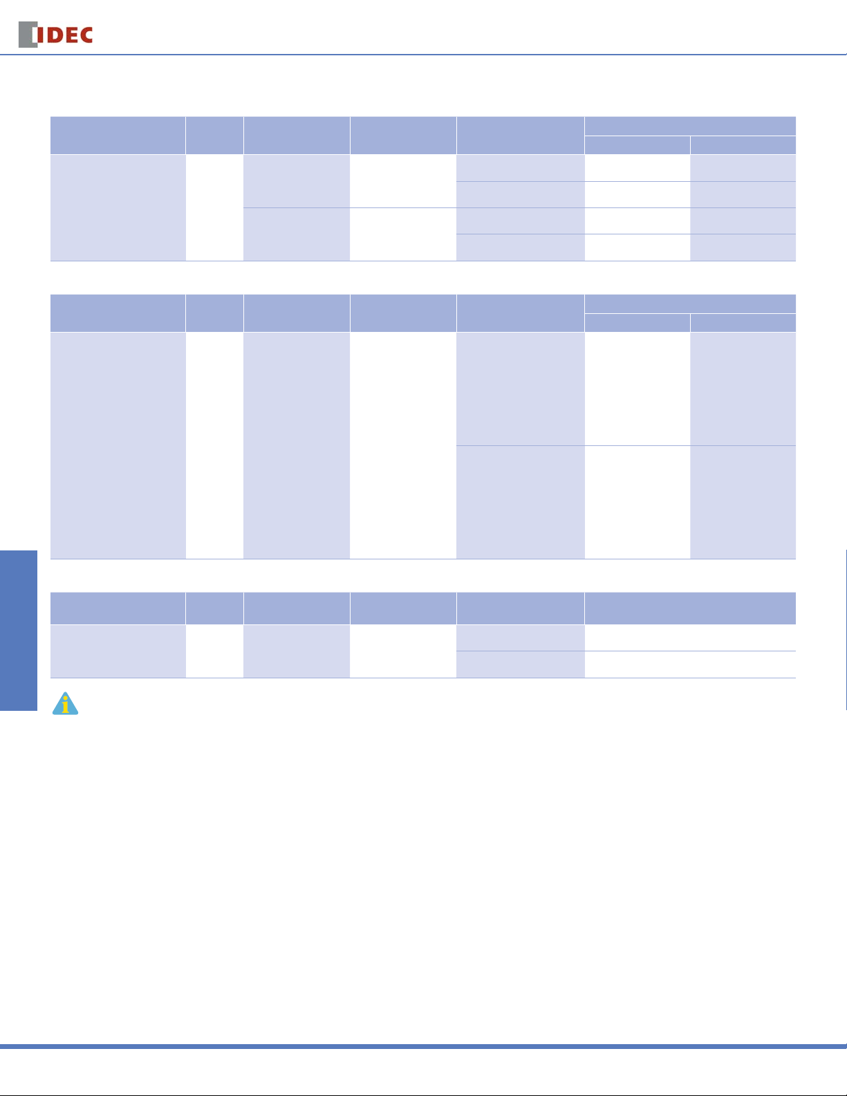
Part Numbers: GT3D-1/GT3D-2/GT3D-3
Mode of Operation
1-A: ON-delay 1
1-B: Interval 1 fi rst
Switches & Pilot LightsDisplay LightsRelays & SocketsTimersTerminal Blocks
1-C: Cycle 1 (OFF fi rst)
1-D: Cycle 3 (ON fi rst)
Part Numbers: GT3D-4
Mode of Operation
1-A: ON-delay 1
1-B: Interval 1 fi rst
1-C: Cycle 1 (OFF fi rst)
1-D: Cycle 3 (ON fi rst)
2-A: ON-delay 2
2-B: Cycle 2
2-C: Signal ON/OFF-delay 1
2-D: Signal OFF-delay 1
2-E: Interval 2
2-F: One-shot cycle
3-A: Signal ON/OFF-delay 2
3-B: Signal OFF-delay 2
3-C: One-shot 1
3-D: One-shot ON-delay
3-E: One-shot 2
3-F: Signal ON/OFF-delay 3
Time
Range
0.01s to
99.9 hours
Time
Range
0.01s to
99.9 hours
Part Number List
Output Contact Rated Voltage Code
250V AC, 3A,
30V DC, 1A
(resistive load)
240V AC,
24V DC, 5A
(resistive load)
Output Contact Rated Voltage Code
240V AC/24V DC, 5A
(resistive load)
Delayed SPDT
+ instantaneous SPDT
Delayed DPDT
Delayed DPDT
100 to 240V AC (50/60Hz) GT3D-2AF20 GT3D-2EAF20
100 to 240V AC (50/60Hz) GT3D-3AF20 GT3D-3EAF20
100 to 240V AC (50/60Hz) GT3D-4AF20 GT3D-4EAF20
Timers
Complete Part No.
8-Pin 11-Pin
24V AC/DC GT3D-2AD24 —
24V AC/DC GT3D-3AD24 —
Complete Part No.
A (11-Pin) B (11-Pin)
24V AC/DC GT3D-4AD24 —
Part Numbers: GT3D-8
Mode of Operation
1: ON-delay one-shot 1
2: Cycle one-shot
3: ON-delay one-shot 2
1. For wiring schematics and timing diagrams GT3D, see pages 815 to 822.
2. For more details about time ranges, see instructions on page 823.
3. A (11-pin) and B (11-pin) differ in the way inputs are wired.
4. For socket and accessory part numbers, see page 838.
5. For timing diagrams overview, see page 794.
Time
Range
0.01s to
99.9 hours
240V AC/24V DC, 5A
(resistive load)
Output Contact Rated Voltage Code Complete Part No. (11-Pin)
100 to 240V AC (50/60Hz) GT3D-8AF20
Delayed DPDT
24V AC/DC GT3D-8AD24
Circuit Breakers
814
www.idec.com
Page 3
Timers
GT3D Series
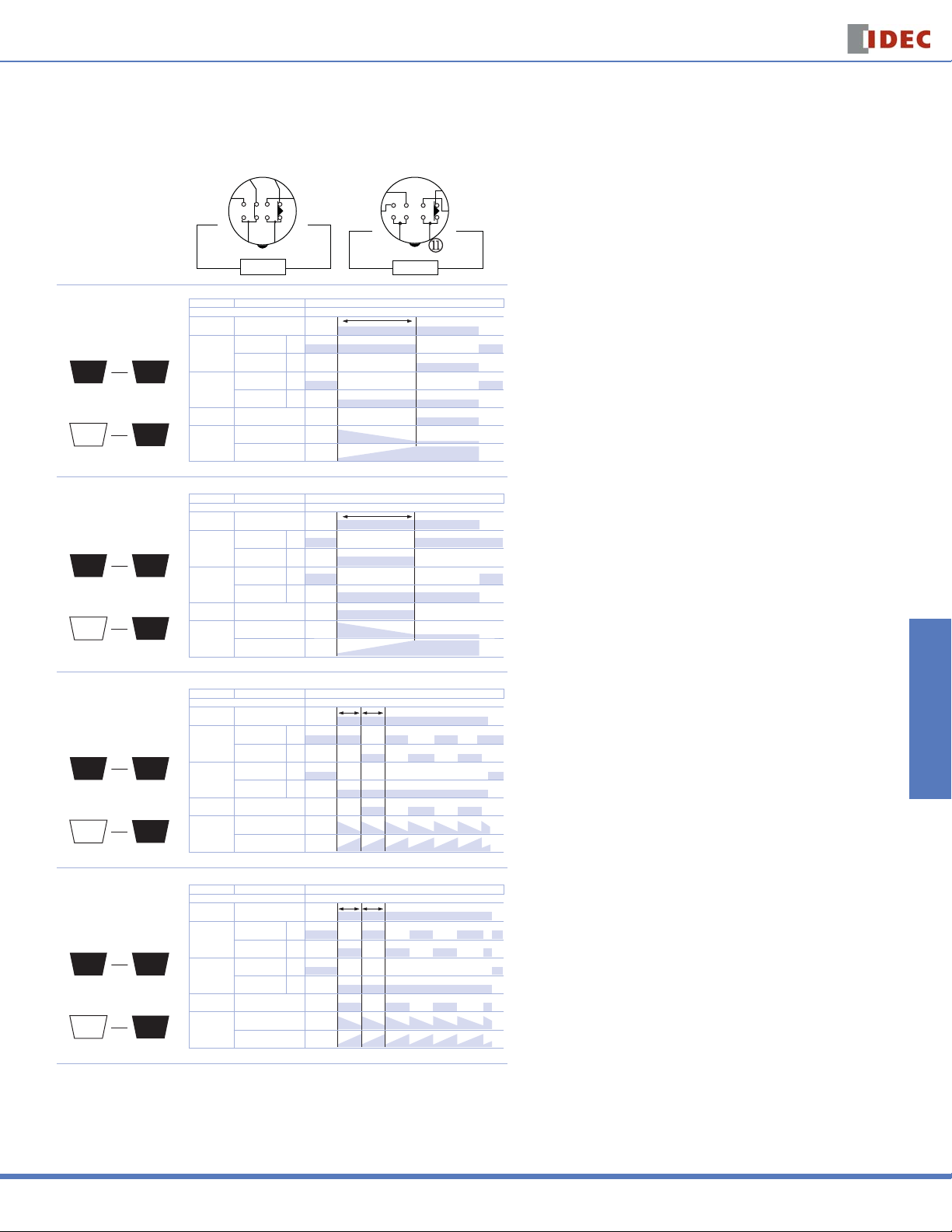
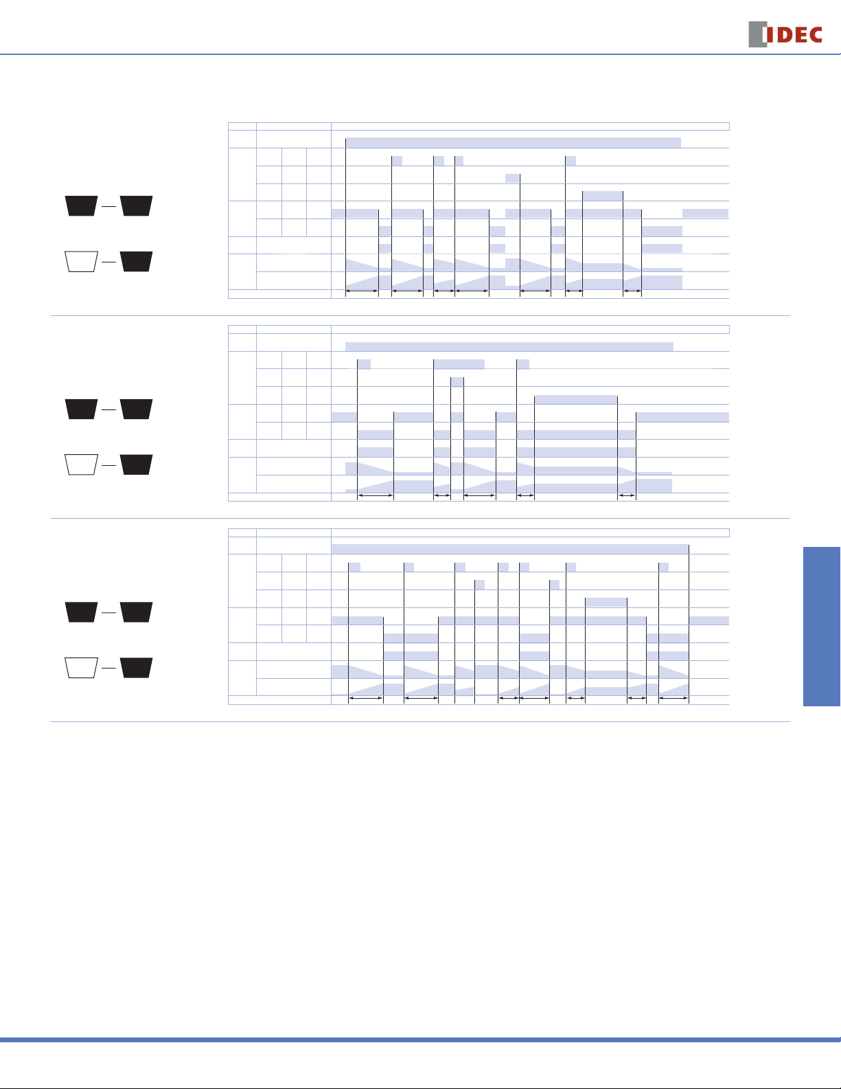
GT3D-2 Timing Diagrams
Delayed SPDT + Instantaneous SPDT
8-Pin 11-Pin
m
n
Operation
Mode Selection
ON-Delay 1
Time Remaining
1
Time Elapsed
1
Interval 1
Time Remaining
1
Time Elapsed
1
A
A
B
B
l
k
q
j
POWER POWER
Item Terminal Number Operation
Item Terminal Number Operation
Set Time Set Time
Set Time Set Time
2 - 7 (8p)
2 - 7 (8p)
Power
Power
2 - 10 (11p)
2 - 10 (11p)
1 - 4, 5 - 8 (8p)
1 - 4, 5 - 8 (8p)
Delayed
Delayed
1 - 4, 8 - 11 (11p)
1 - 4, 8 - 11 (11p)
1 - 3, 6 - 8 (8p)
1 - 3, 6 - 8 (8p)
Contact
Contact
1 - 3, 9 - 11 (11p)
1 - 3, 9 - 11 (11p)
1 - 4 (NC)
Instantaneous
Instantaneous
Contact
Contact
Indicator OUT
Indicator OUT
Digital Time
Digital Time
Display
Display
Item Terminal Number Operation
Item Terminal Number Operation
Set Time Set Time
Set Time Set Time
Power
Power
Delayed
Delayed
Contact
Contact
Instantaneous
Instantaneous
Contact
Contact
Indicator OUT
Indicator OUT
Digital Time
Digital Time
Display
Display
1 - 4 (NC)
1 - 3 (NO)
1 - 3 (NO)
DOWN
DOWN
UP
UP
2 - 7 (8p)
2 - 7 (8p)
2 - 10 (11p)
2 - 10 (11p)
1 - 4, 5 - 8 (8p)
1 - 4, 5 - 8 (8p)
1 - 4, 8 - 11 (11p)
1 - 4, 8 - 11 (11p)
1 - 3, 6 - 8 (8p)
1 - 3, 6 - 8 (8p)
1 - 3, 9 - 11 (11p)
1 - 3, 9 - 11 (11p)
1 - 4 (NC)
1 - 4 (NC)
1 - 3 (NO)
1 - 3 (NO)
DOWN
DOWN
UP
UP
(NC)
(NC)
(NO)
(NO)
(NC)
(NC)
(NO)
(NO)
o
p
Timing Diagrams/Schematics
o
p
n
m
l
(+)(-)
k
j
q
s
r
(+)(-)
Switches & Pilot Lights Display Lights Relays & Sockets Timers Terminal Blocks
Cycle 1
(OFF fi rst)
Time Remaining
1
Time Elapsed
1
Cycle 3
(ON fi rst)
Time Remaining
1
Time Elapsed
1
Item Terminal Number Operation
Item Terminal Number Operation
Set Time Set Time
Set Time Set Time
2 - 7 (8p)
2 - 7 (8p)
Power
Power
2 - 10 (11p)
2 - 10 (11p)
1 - 4, 5 - 8 (8p)
1 - 4, 5 - 8 (8p)
Delayed
Delayed
1 - 4, 8 - 11 (11p)
1 - 4, 8 - 11 (11p)
1 - 3, 6 - 8 (8p)
1 - 3, 6 - 8 (8p)
Contact
Contact
1 - 3, 9 - 11 (11p)
1 - 3, 9 - 11 (11p)
1 - 4 (NC)
C
Instantaneous
Instantaneous
Contact
Contact
Indicator OUT
Indicator OUT
Digital Time
Digital Time
C
Display
Display
Item Terminal Number Operation
Item Terminal Number Operation
Set Time Set Time
Set Time Set Time
Power
Power
Delayed
Delayed
Contact
Contact
D
Instantaneous
Instantaneous
Contact
Contact
Indicator OUT
Indicator OUT
Digital Time
Digital Time
D
Display
Display
1 - 4 (NC)
1 - 3 (NO)
1 - 3 (NO)
DOWN
DOWN
UP
UP
2 - 7 (8p)
2 - 7 (8p)
2 - 10 (11p)
2 - 10 (11p)
1 - 4, 5 - 8 (8p)
1 - 4, 5 - 8 (8p)
1 - 4, 8 - 11 (11p)
1 - 4, 8 - 11 (11p)
1 - 3, 6 - 8 (8p)
1 - 3, 6 - 8 (8p)
1 - 3, 9 - 11 (11p)
1 - 3, 9 - 11 (11p)
1 - 4 (NC)
1 - 4 (NC)
1 - 3 (NO)
1 - 3 (NO)
DOWN
DOWN
UP
UP
(NC)
(NC)
(NO)
(NO)
(NC)
(NC)
(NO)
(NO)
Circuit Breakers
USA: 800-262-IDEC Canada: 888-317-IDEC
815
Page 4
GT3D Series
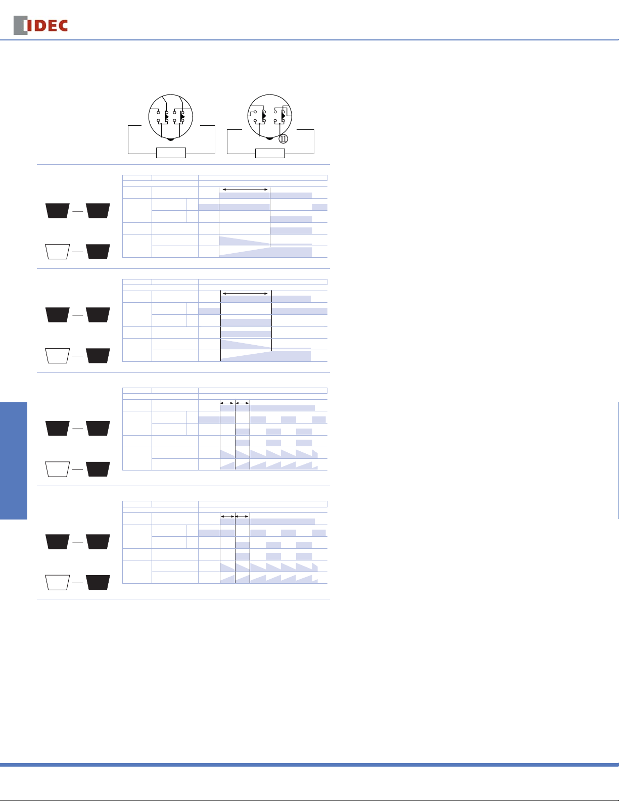
GT3D-3 Timing Diagrams
Delayed DPDT
Timers
Operation
Mode Selection
Switches & Pilot LightsDisplay LightsRelays & SocketsTimersTerminal Blocks
ON-Delay 1
Time Remaining
1
Time Elapsed
1
Interval 1
Time Remaining
1
Time Elapsed
1
8-Pin 11-Pin
m
n
l
k
q
j
POWER POWER
Item Terminal Number Operation
Item Terminal Number Operation
Set Time Set Time
Set Time Set Time
2 - 7 (8p)
2 - 7 (8p)
Power
Power
2 - 10 (11p)
2 - 10 (11p)
1 - 4, 5 - 8 (8p)
1 - 4, 5 - 8 (8p)
Delayed
Delayed
1 - 4, 8 - 11 (11p)
A
A
B
B
1 - 4, 8 - 11 (11p)
1 - 3, 6 - 8 (8p)
1 - 3, 6 - 8 (8p)
Contact
Contact
1 - 3, 9 - 11 (11p)
1 - 3, 9 - 11 (11p)
Indicator OUT
Indicator OUT
DOWN
DOWN
Digital Time
Digital Time
Display
Display
UP
UP
Item Terminal Number Operation
Item Terminal Number Operation
Set Time Set Time
Set Time Set Time
2 - 7 (8p)
2 - 7 (8p)
Power
Power
2 - 10 (11p)
2 - 10 (11p)
1 - 4, 5 - 8 (8p)
1 - 4, 5 - 8 (8p)
Delayed
Delayed
1 - 4, 8 - 11 (11p)
1 - 4, 8 - 11 (11p)
1 - 3, 6 - 8 (8p)
1 - 3, 6 - 8 (8p)
Contact
Contact
1 - 3, 9 - 11 (11p)
1 - 3, 9 - 11 (11p)
Indicator OUT
Indicator OUT
DOWN
DOWN
Digital Time
Digital Time
Display
Display
UP
UP
(NC)
(NC)
(NO)
(NO)
(NC)
(NC)
(NO)
(NO)
o
p
o
p
n
m
l
(+)(-)
k
j
q
s
r
(+)(-)
Cycle 1
(OFF fi rst)
Time Remaining
1
Time Elapsed
1
Cycle 3
(ON fi rst)
Time Remaining
1
Time Elapsed
1
Item Terminal Number Operation
Item Terminal Number Operation
Set Time Set Time
Set Time Set Time
2 - 7 (8p)
2 - 7 (8p)
Power
Power
2 - 10 (11p)
2 - 10 (11p)
1 - 4, 5 - 8 (8p)
1 - 4, 5 - 8 (8p)
Delayed
Delayed
1 - 4, 8 - 11 (11p)
1 - 4, 8 - 11 (11p)
1 - 3, 6 - 8 (8p)
1 - 3, 6 - 8 (8p)
Contact
Contact
C
C
D
D
1 - 3, 9 - 11 (11p)
1 - 3, 9 - 11 (11p)
Indicator OUT
Indicator OUT
DOWN
DOWN
Digital Time
Digital Time
Display
Display
UP
UP
Item Terminal Number Operation
Item Terminal Number Operation
Set Time Set Time
Set Time Set Time
2 - 7 (8p)
2 - 7 (8p)
Power
Power
2 - 10 (11p)
2 - 10 (11p)
1 - 4, 5 - 8 (8p)
1 - 4, 5 - 8 (8p)
Delayed
Delayed
1 - 4, 8 - 11 (11p)
1 - 4, 8 - 11 (11p)
1 - 3, 6 - 8 (8p)
1 - 3, 6 - 8 (8p)
Contact
Contact
1 - 3, 9 - 11 (11p)
1 - 3, 9 - 11 (11p)
Indicator OUT
Indicator OUT
DOWN
DOWN
Digital Time
Digital Time
Display
Display
UP
UP
(NC)
(NC)
(NO)
(NO)
(NC)
(NC)
(NO)
(NO)
Circuit Breakers
816
www.idec.com
Page 5

Timers
GT3D Series
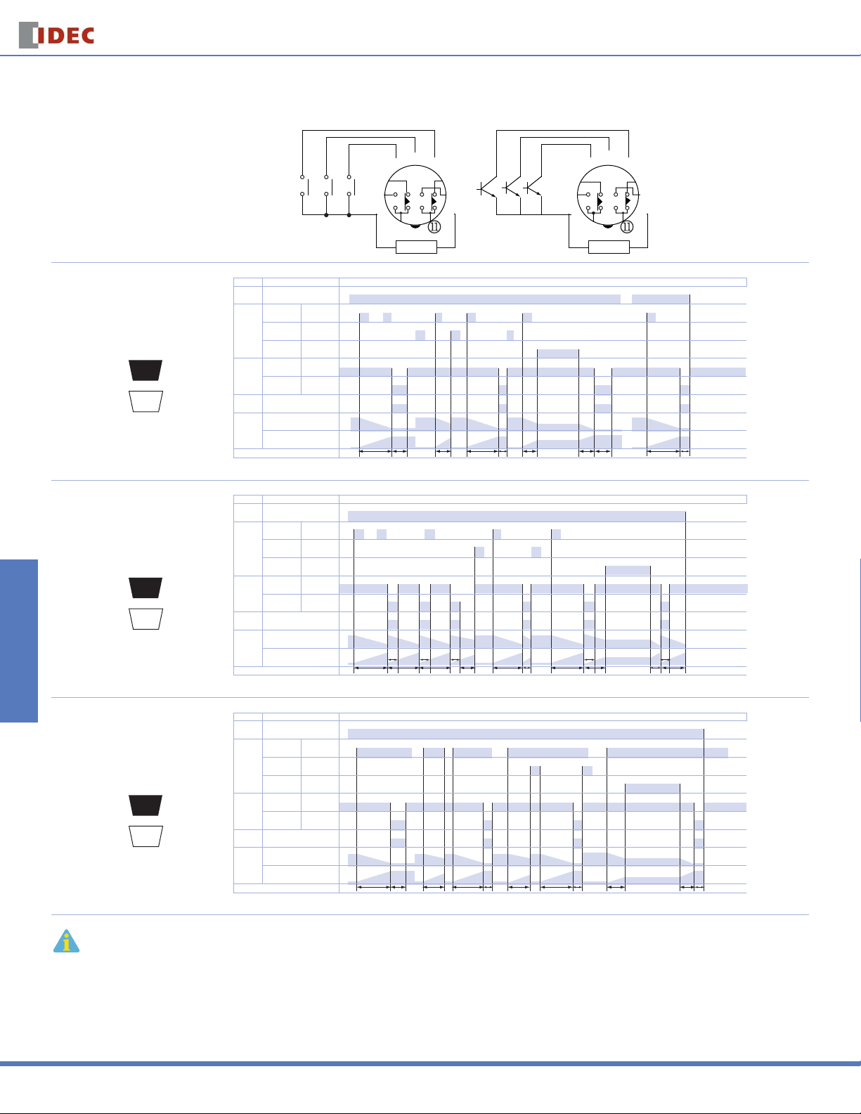
GT3D-4 Timing Diagrams
These timers require a start input. A gate and reset input are optional. Inputs are controlled by external pushbuttons. Reset occurs when the power is removed or
when the reset input is supplied. The gate signal can be used to interrupt (freeze) timer functions. Timer functions resume when the gate input is removed. B style
timers are not equipped for gate input.
Delayed DPDT
Operation
Mode
Selection
ON-Delay 1
Time Remaining
1
Time Elapsed
1
(A Type)
(Contact Input)
Reset Start Gate
A
A
m
l
k
(Transistor Input)
m
l
k
n
j
POWER
T
o
p
o
p
n
q
Reset Start Gate
r
s
(NC)
(NC)
(NO)
(NO)
DOWN
DOWN
UP
UP
(+)(-)
1 - 4
1 - 4
8 - 11
8 - 11
1 - 3
1 - 3
9 - 11
9 - 11
8 - 11
8 - 11
9 - 11
9 - 11
j
POWER
Item Terminal Number Operation
Item Terminal Number Operation
Power 2 - 10
Power 2 - 10
Delayed
Delayed
Contact
Contact
Indicator OUT
Indicator OUT
Digital Time
Digital Time
Display
Display
Set Time
Set Time
q
s
r
(+)(-)
(B Type)
(Contact Input)
Start Reset
n
m
l
k
j
o
POWER
p
(Transistor Input)
Start Reset
q
r
s
(+)(-)
m
l
k
n
j
POWER
o
p
q
r
s
Switches & Pilot Lights Display Lights Relays & Sockets Timers Terminal Blocks
(+)(-)
Interval 1
Time Remaining
1
Time Elapsed
1
Item Terminal Number Operation
Item Terminal Number Operation
Power 2 - 10
Power 2 - 10
Delayed
Delayed
Contact
B
B
Contact
Indicator OUT
Indicator OUT
Digital Time
Digital Time
Display
Display
Set Time
Set Time
(NC)
(NC)
(NO)
(NO)
DOWN
DOWN
UP
UP
1 - 4
1 - 4
8 - 11
8 - 11
1 - 3
1 - 3
9 - 11
9 - 11
8 - 11
8 - 11
9 - 11
9 - 11
T
Circuit Breakers
USA: 800-262-IDEC Canada: 888-317-IDEC
817
Page 6

GT3D Series
Timers
GT3D-4 Timing Diagrams
Cycle 1
(OFF fi rst)
Time Remaining
Switches & Pilot LightsDisplay LightsRelays & SocketsTimersTerminal Blocks
1
Time Elapsed
1
Cycle 3
(ON fi rst)
Time Remaining
1
Time Elapsed
1
ON-Delay 2
Time Remaining
2
Time Elapsed
2
Item Terminal Number Operation
Item Terminal Number Operation
Power 2 - 10
Power 2 - 10
Delayed
Delayed
Contact
Contact
C
C
D
D
A
A
Indicator OUT
Indicator OUT
Digital Time
Digital Time
Display
Display
Set Time
Set Time
Item Terminal Number Operation
Item Terminal Number Operation
Power 2 - 10
Power 2 - 10
Delayed
Delayed
Contact
Contact
Indicator OUT
Indicator OUT
Digital Time
Digital Time
Display
Display
Set Time
Set Time
Item Terminal Number Operation
Item Terminal Number Operation
Power 2 - 10
Power 2 - 10
Input
Input
Delayed
Delayed
Contact
Contact
Indicator OUT
Indicator OUT
Digital
Digital
Time
Time
Display
Display
Set Time
Set Time
Start
Start
ON or L
ON or L
Reset
Reset
ON or L
ON or L
Gate
Gate
ON or L
ON or L
(NC)
(NC)
(NO)
(NO)
DOWN
DOWN
UP
UP
(NC)
(NC)
(NO)
(NO)
DOWN
DOWN
UP
UP
(NC)
(NC)
(NO)
(NO)
DOWN
DOWN
UP
UP
2 - 6 (A)
2 - 6 (A)
5 - 7 (B)
5 - 7 (B)
2 - 7 (A)
2 - 7 (A)
6 - 7 (B)
6 - 7 (B)
2 - 5 (A) 3 - 5
2 - 5 (A) 3 - 5
8 - 11
8 - 11
9 - 11
9 - 11
8 - 11
8 - 11
9 - 11
9 - 11
1 - 4
1 - 4
8 - 11
8 - 11
1 - 3
1 - 3
9 - 11
9 - 11
1 - 4
1 - 4
1 - 3
1 - 3
1 - 4
1 - 4
1 - 3
1 - 3
8 - 11
8 - 11
9 - 11
9 - 11
T T T T TT
8 - 11
8 - 11
9 - 11
9 - 11
T T T T TT
3 - 6
3 - 6
3 - 7
3 - 7
8 - 11
8 - 11
9 - 11
9 - 11
T T T T T T T T T T T T
T
T’ T’Ta
Circuit Breakers
818
www.idec.com
Page 7

Timers
GT3D Series
Cycle 2
Time Remaining
2
B
Time Elapsed
2
Signal ON/OFF-Delay 1
B
Time Remaining
2
C
Time Elapsed
2
C
GT3D-4 Timing Diagrams
Item Terminal Number Operation
Item Terminal Number Operation
Power 2 - 10
Power 2 - 10
Start
2 - 6 (A)
Start
2 - 6 (A)
3 - 6
5 - 7 (B)
5 - 7 (B)
2 - 7 (A)
2 - 7 (A)
6 - 7 (B)
6 - 7 (B)
2 - 5 (A) 3 - 5
2 - 5 (A) 3 - 5
1 - 4
1 - 4
8 - 11
8 - 11
8 - 11
8 - 11
1 - 3
1 - 3
9 - 11
9 - 11
9 - 11
9 - 11
2 - 6 (A)
2 - 6 (A)
5 - 7 (B)
5 - 7 (B)
2 - 7 (A)
2 - 7 (A)
6 - 7 (B)
6 - 7 (B)
2 - 5 (A) 3 - 5
2 - 5 (A) 3 - 5
1 - 4
1 - 4
8 - 11
8 - 11
8 - 11
8 - 11
1 - 3
1 - 3
9 - 11
9 - 11
9 - 11
9 - 11
3 - 6
3 - 7
3 - 7
T T T T T T T T T T T T
3 - 6
3 - 6
3 - 7
3 - 7
T T T TTa Ta Ta Ta
T
ON or L
ON or L
Reset
Reset
Input
Input
ON or L
ON or L
Gate
Gate
ON or L
ON or L
(NC)
(NC)
Delayed
Delayed
Contact
Contact
(NO)
(NO)
Indicator OUT
Indicator OUT
DOWN
DOWN
Digital
Digital
Time
Time
Display
Display
UP
UP
Set Time
Set Time
Item Terminal Number Operation
Item Terminal Number Operation
Power 2 - 10
Power 2 - 10
Start
Start
ON or L
ON or L
Reset
Reset
Input
Input
ON or L
ON or L
Gate
Gate
ON or L
ON or L
(NC)
(NC)
Delayed
Delayed
Contact
Contact
(NO)
(NO)
Indicator OUT
Indicator OUT
DOWN
DOWN
Digital
Digital
Time
Time
Display
Display
UP
UP
Set Time
Set Time
Switches & Pilot Lights Display Lights Relays & Sockets Timers Terminal Blocks
T’ T’Ta
T’ T”
Singal OFF-Delay 1
Time Remaining
2
Time Elapsed
2
Interval 2
Time Remaining
2
Time Elapsed
2
Item Terminal Number Operation
Item Terminal Number Operation
Power 2 - 10
Power 2 - 10
Start
2 - 6 (A)
Start
2 - 6 (A)
3 - 6
5 - 7 (B)
5 - 7 (B)
2 - 7 (A)
2 - 7 (A)
6 - 7 (B)
6 - 7 (B)
2 - 5 (A) 3 - 5
2 - 5 (A) 3 - 5
1 - 4
1 - 4
8 - 11
8 - 11
8 - 11
8 - 11
1 - 3
1 - 3
9 - 11
9 - 11
9 - 11
9 - 11
2 - 6 (A)
2 - 6 (A)
5 - 7 (B)
5 - 7 (B)
2 - 7 (A)
2 - 7 (A)
6 - 7 (B)
6 - 7 (B)
2 - 5 (A) 3 - 5
2 - 5 (A) 3 - 5
1 - 4
1 - 4
8 - 11
8 - 11
8 - 11
8 - 11
1 - 3
1 - 3
9 - 11
9 - 11
9 - 11
9 - 11
3 - 6
3 - 7
3 - 7
3 - 6
3 - 6
3 - 7
3 - 7
T Ta TTa T’ T”
T Ta T’ T”
Circuit Breakers
ON or L
ON or L
Reset
Reset
Input
Input
ON or L
ON or L
Gate
Gate
ON or L
D
D
E
E
ON or L
(NC)
(NC)
Delayed
Delayed
Contact
Contact
(NO)
(NO)
Indicator OUT
Indicator OUT
DOWN
DOWN
Digital
Digital
Time
Time
Display
Display
UP
UP
Set Time
Set Time
Item Terminal Number Operation
Item Terminal Number Operation
Power 2 - 10
Power 2 - 10
Start
Start
ON or L
ON or L
Reset
Reset
Input
Input
ON or L
ON or L
Gate
Gate
ON or L
ON or L
(NC)
(NC)
Delayed
Delayed
Contact
Contact
(NO)
(NO)
Indicator OUT
Indicator OUT
DOWN
DOWN
Digital
Digital
Time
Time
Display
Display
UP
UP
Set Time
Set Time
USA: 800-262-IDEC Canada: 888-317-IDEC
819
Page 8

One-Shot Cycle
Time Remaining
Switches & Pilot LightsDisplay LightsRelays & SocketsTimersTerminal Blocks
2
Time Elapsed
2
Signal ON/OFF-Delay 2
Time Remaining
3
Time Elapsed
3
GT3D Series
F
F
A
A
GT3D-4 Timing Diagrams
Item Terminal Number Operation
Item Terminal Number Operation
Power 2 - 10
Power 2 - 10
Start
2 - 6 (A)
Start
2 - 6 (A)
3 - 6
5 - 7 (B)
5 - 7 (B)
2 - 7 (A)
2 - 7 (A)
6 - 7 (B)
6 - 7 (B)
2 - 5 (A) 3 - 5
2 - 5 (A) 3 - 5
1 - 4
1 - 4
8 - 11
8 - 11
8 - 11
8 - 11
1 - 3
1 - 3
9 - 11
9 - 11
9 - 11
9 - 11
2 - 6 (A)
2 - 6 (A)
5 - 7 (B)
5 - 7 (B)
2 - 7 (A)
2 - 7 (A)
6 - 7 (B)
6 - 7 (B)
2 - 5 (A) 3 - 5
2 - 5 (A) 3 - 5
1 - 4
1 - 4
8 - 11
8 - 11
8 - 11
8 - 11
1 - 3
1 - 3
9 - 11
9 - 11
9 - 11
9 - 11
3 - 6
3 - 7
3 - 7
T T T TTa T’ T”
3 - 6
3 - 6
3 - 7
3 - 7
T T Ta Ta TaT T TT’ T”
ON or L
ON or L
Reset
Reset
Input
Input
ON or L
ON or L
Gate
Gate
ON or L
ON or L
(NC)
(NC)
Delayed
Delayed
Contact
Contact
(NO)
(NO)
Indicator OUT
Indicator OUT
DOWN
DOWN
Digital
Digital
Time
Time
Display
Display
UP
UP
Set Time
Set Time
Item Terminal Number Operation
Item Terminal Number Operation
Power 2 - 10
Power 2 - 10
Start
Start
ON or L
ON or L
Reset
Reset
Input
Input
ON or L
ON or L
Gate
Gate
ON or L
ON or L
(NC)
(NC)
Delayed
Delayed
Contact
Contact
(NO)
(NO)
Indicator OUT
Indicator OUT
DOWN
DOWN
Digital
Digital
Time
Time
Display
Display
UP
UP
Set Time
Set Time
Timers
Singal OFF-Delay 2
Time Remaining
3
Time Elapsed
3
One-Shot 1
Time Remaining
3
Time Elapsed
3
Item Terminal Number Operation
Item Terminal Number Operation
Power 2 - 10
Power 2 - 10
Start
2 - 6 (A)
Start
2 - 6 (A)
3 - 6
5 - 7 (B)
5 - 7 (B)
2 - 7 (A)
2 - 7 (A)
6 - 7 (B)
6 - 7 (B)
2 - 5 (A) 3 - 5
2 - 5 (A) 3 - 5
1 - 4
1 - 4
8 - 11
8 - 11
8 - 11
8 - 11
1 - 3
1 - 3
9 - 11
9 - 11
9 - 11
9 - 11
2 - 6 (A)
2 - 6 (A)
5 - 7 (B)
5 - 7 (B)
2 - 7 (A)
2 - 7 (A)
6 - 7 (B)
6 - 7 (B)
2 - 5 (A) 3 - 5
2 - 5 (A) 3 - 5
1 - 4
1 - 4
8 - 11
8 - 11
8 - 11
8 - 11
1 - 3
1 - 3
9 - 11
9 - 11
9 - 11
9 - 11
3 - 6
3 - 7
3 - 7
3 - 6
3 - 6
3 - 7
3 - 7
T TTa Ta T’ T”
TTa TaTa T’ T” T”
ON or L
ON or L
Reset
Reset
Input
Input
ON or L
ON or L
Gate
Gate
ON or L
B
B
C
C
ON or L
(NC)
(NC)
Delayed
Delayed
Contact
Contact
(NO)
(NO)
Indicator OUT
Indicator OUT
DOWN
DOWN
Digital
Digital
Time
Time
Display
Display
UP
UP
Set Time
Set Time
Item Terminal Number Operation
Item Terminal Number Operation
Power 2 - 10
Power 2 - 10
Start
Start
ON or L
ON or L
Reset
Reset
Input
Input
ON or L
ON or L
Gate
Gate
ON or L
ON or L
(NC)
(NC)
Delayed
Delayed
Contact
Contact
(NO)
(NO)
Indicator OUT
Indicator OUT
DOWN
DOWN
Digital
Digital
Time
Time
Display
Display
UP
UP
Set Time
Set Time
Circuit Breakers
820
www.idec.com
Page 9
Timers
GT3D Series
One-Shot ON-Delay
Time Remaining
3
D
Time Elapsed
3
One-Shot 2
D
Time Remaining
3
E
Time Elapsed
3
E
GT3D-4 Timing Diagrams
Item Terminal Number Operation
Item Terminal Number Operation
Power 2 - 10
Power 2 - 10
Start
2 - 6 (A)
Start
2 - 6 (A)
3 - 6
5 - 7 (B)
5 - 7 (B)
2 - 7 (A)
2 - 7 (A)
6 - 7 (B)
6 - 7 (B)
2 - 5 (A) 3 - 5
2 - 5 (A) 3 - 5
1 - 4
1 - 4
8 - 11
8 - 11
8 - 11
8 - 11
1 - 3
1 - 3
9 - 11
9 - 11
9 - 11
9 - 11
2 - 6 (A)
2 - 6 (A)
5 - 7 (B)
5 - 7 (B)
2 - 7 (A)
2 - 7 (A)
6 - 7 (B)
6 - 7 (B)
2 - 5 (A) 3 - 5
2 - 5 (A) 3 - 5
1 - 4
1 - 4
8 - 11
8 - 11
8 - 11
8 - 11
1 - 3
1 - 3
9 - 11
9 - 11
9 - 11
9 - 11
3 - 6
3 - 7
3 - 7
3 - 6
3 - 6
3 - 7
3 - 7
T T TTTa T’ T”
TT Ta T’ T”
ON or L
ON or L
Reset
Reset
Input
Input
ON or L
ON or L
Gate
Gate
ON or L
ON or L
(NC)
(NC)
Delayed
Delayed
Contact
Contact
(NO)
(NO)
Indicator OUT
Indicator OUT
DOWN
DOWN
Digital
Digital
Time
Time
Display
Display
UP
UP
Set Time
Set Time
Item Terminal Number Operation
Item Terminal Number Operation
Power 2 - 10
Power 2 - 10
Start
Start
ON or L
ON or L
Reset
Reset
Input
Input
ON or L
ON or L
Gate
Gate
ON or L
ON or L
(NC)
(NC)
Delayed
Delayed
Contact
Contact
(NO)
(NO)
Indicator OUT
Indicator OUT
DOWN
DOWN
Digital
Digital
Time
Time
Display
Display
UP
UP
Set Time
Set Time
Switches & Pilot Lights Display Lights Relays & Sockets Timers Terminal Blocks
Signal ON/OFF-Delay 3
Time Remaining
3
F
Time Elapsed
3
F
Item Terminal Number Operation
Item Terminal Number Operation
Power 2 - 10
Power 2 - 10
Start
2 - 6 (A)
Start
2 - 6 (A)
3 - 6
Input
Input
Delayed
Delayed
Contact
Contact
Indicator OUT
Indicator OUT
DOWN
DOWN
Digital
Digital
Time
Time
Display
Display
UP
UP
Set Time
Set Time
ON or L
ON or L
Reset
Reset
ON or L
ON or L
Gate
Gate
ON or L
ON or L
(NC)
(NC)
(NO)
(NO)
5 - 7 (B)
5 - 7 (B)
2 - 7 (A)
2 - 7 (A)
6 - 7 (B)
6 - 7 (B)
2 - 5 (A) 3 - 5
2 - 5 (A) 3 - 5
1 - 4
1 - 4
8 - 11
8 - 11
8 - 11
8 - 11
1 - 3
1 - 3
9 - 11
9 - 11
9 - 11
9 - 11
3 - 6
3 - 7
3 - 7
TT TaTa Ta T’ T”
Circuit Breakers
USA: 800-262-IDEC Canada: 888-317-IDEC
821
Page 10
GT3D Series
GT3D-8 Timing Diagrams
Delayed DPDT
Timers
Operation
Mode Selection
Switches & Pilot LightsDisplay LightsRelays & SocketsTimersTerminal Blocks
ON-Delay One-Shot 1
Time Remaining
Time Elapsed
Cycle One-Shot
Time Remaining
Time Elapsed
(Contact Input)
o
p
Reset Start Gate
n
m
l
k
q
r
s
j
POWER
Item Terminal Number Operation
Item Terminal Number Operation
Power 2 - 10
Power 2 - 10
Start
Start
2 - 6
2 - 6
ON or L
ON or L
Reset
Reset
Input
Input
Delayed
1
1
2
2
Delayed
Contact
Contact
Indicator OUT
Indicator OUT
DOWN
DOWN
Digital
Digital
Time
Time
Display
Display
UP
UP
Set Time
Set Time
Item Terminal Number Operation
Item Terminal Number Operation
Power 2 - 10
Power 2 - 10
Input
Input
Delayed
Delayed
Contact
Contact
Indicator OUT
Indicator OUT
DOWN
DOWN
Digital
Digital
Time
Time
Display
Display
UP
UP
Set Time
Set Time
ON or L
ON or L
Gate
Gate
ON or L
ON or L
(NC)
(NC)
(NO)
(NO)
Start
Start
ON or L
ON or L
Reset
Reset
ON or L
ON or L
Gate
Gate
ON or L
ON or L
(NC)
(NC)
(NO)
(NO)
2 - 7
2 - 7
2 - 5
2 - 5
1 - 4
1 - 4
8 - 11
8 - 11
1 - 3
1 - 3
9 - 11
9 - 11
2 - 6
2 - 6
2 - 7
2 - 7
2 - 5
2 - 5
1 - 4
1 - 4
8 - 11
8 - 11
1 - 3
1 - 3
9 - 11
9 - 11
T TTTa TbTbTo ToT’ T”
To To To To To
T T T T T T’ Ta
(Transistor Input)
o
p
Reset Start Gate
(+)(-)
Ta Tb T”
m
l
k
n
q
r
s
j
POWER
(+)(-)
ON-Delay One-Shot 2
Time Remaining
Time Elapsed
T = Set time
Ta = Shorter than set time
Tb = Shorter than single-shot output time
T = T' + T"
T0 = Single-shot output time (selected from A, B, C, D, E or F)
Circuit Breakers
822
Item Terminal Number Operation
Item Terminal Number Operation
Power 2 - 10
Power 2 - 10
Start
Start
2 - 6
2 - 6
ON or L
ON or L
Reset
Reset
Input
Input
Delayed
3
3
Delayed
Contact
Contact
Indicator OUT
Indicator OUT
DOWN
DOWN
Digital
Digital
Time
Time
Display
Display
UP
UP
Set Time
Set Time
ON or L
ON or L
Gate
Gate
ON or L
ON or L
(NC)
(NC)
(NO)
(NO)
2 - 7
2 - 7
2 - 5
2 - 5
1 - 4
1 - 4
8 - 11
8 - 11
1 - 3
1 - 3
9 - 11
9 - 11
T T TTa TaTb Tb TbTo T’ T”
www.idec.com
Page 11

Timers
GT3D Series
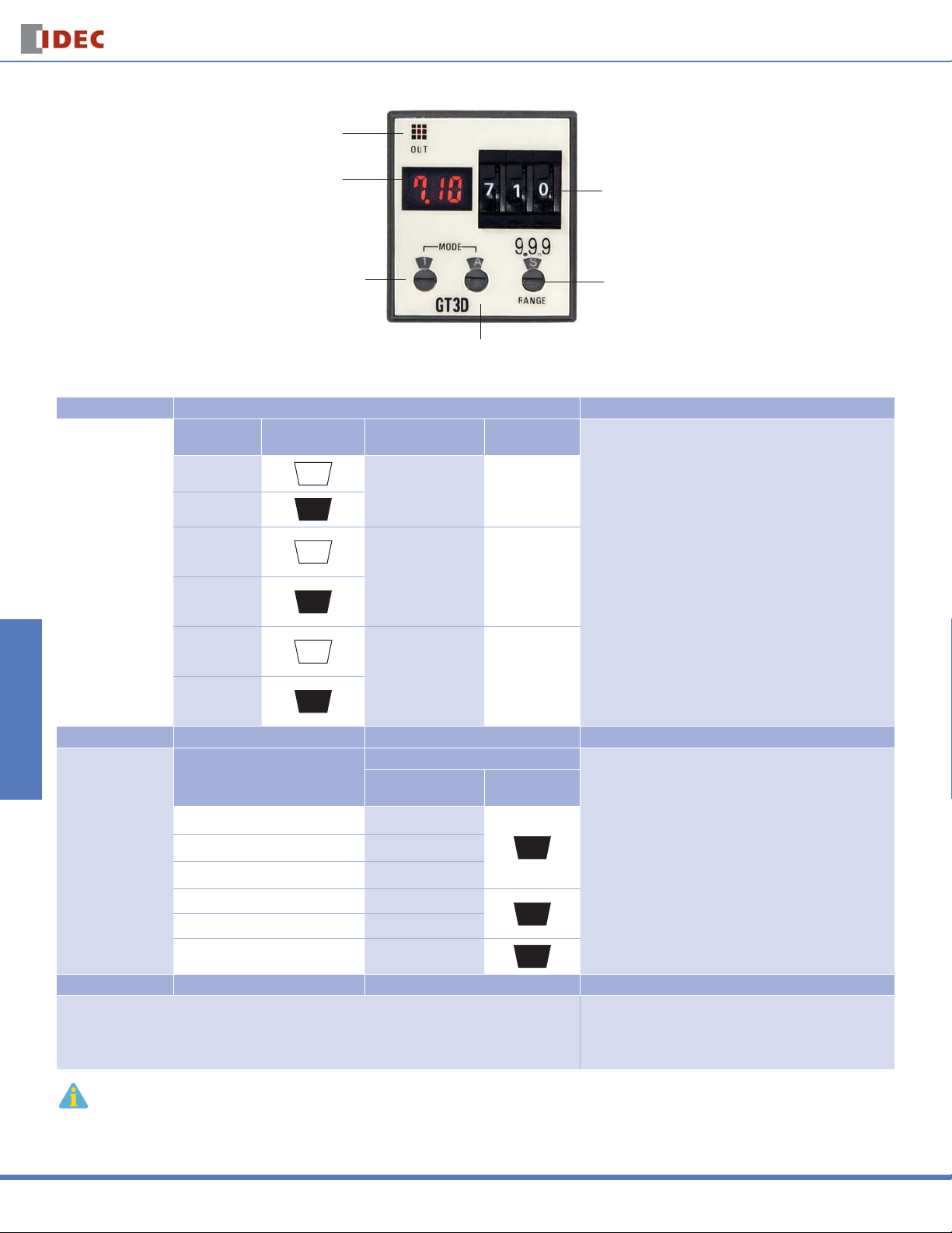
Instructions: Setting GT3D-2, GT3D-3 Timers
Timed OUT Indicator
Digital Time Display
(LCD backlit with red LED)
j Indication Mode Selector
1
1
k One-Shot Time Selector
A, B, C, D
Step 1 Desired Mode/Selection Remarks
Select the desired time
display and operation
modes.
Time Display
Mode
Time elapsed
Time remaining
Time elapsed
Time remaining
Time elapsed
Time remaining
Time elapsed
Time remaining
j Indicator Mode
Selector
1
1
1
1
1
1
1
1
Operation Mode
ON-delay 1
Interval
Cycle 1
Cycle 3
k Operation
Mode Selector
A
A
B
B
C
C
D
D
m Time Setting
Digital Switch
l Time Range Selector
9.99S – 99.9H
1. Use the fl at screwdriver to set the selectors. Since selectors do not
turn all the way around, both clockwise and counterclockwise rotation
may be necessary.
2. The j Indicator Mode Selector determines whether the Digital
Time Display shows the time elapsed or time remaining. The k
Operation Mode Selector determines the desired operation mode.
Decide which display and mode is desired, then use these two selectors jk to set the operation mode.
3. The j Operation Mode Selector has two blank modes which are
not intended for use. Always have this selector set to A, B, C, or D.
Switches & Pilot Lights Display Lights Relays & Sockets Timers Terminal Blocks
Step 2 Desired Operation Selection Remarks
l Time Range Selector
Base Time Ranges
0.01 seconds to 9.99 seconds 9.99
Select a time range
that contains the
desired period of time.
Step 3 Desired Operation Selection Remarks
0.1 seconds to 99.9 seconds 99.9
1 second to 999 seconds 999
0.1 minutes to 99.9 minutes 99.9
1 minute to 999 minutes 999
0.1 hours to 99.9 hours 99.9
Decimal Point
Indicator
Time Increment
Indicator
S
M
H
l Time Range Selector controls both the decimal point indica-
1. The
tor (9.99, 99.9, 999) and the time increment indicators S (seconds), M
(minutes), and H (hours).
2. Chose which base time range contains the targeted timer setting.
Then use the l Time Range Selector to set the decimal point indicator and time increment indicator to its corresponding pair of settings.
3. Since these confi gurations offer a complete range of settings from
0.01 seconds to 99.9 hours, the setting of 9.99 for minutes and the
9.99 and 999 settings for hours are not listed and should not be used.
Use the m Time Setting Digital Switch to set the desired
Set the precise period of time desired by using the m Time Setting Digital Switch.
period of time. It is important to remember that the setting
of the l Time Range Selector determines the units of time
measurement as well as the implied decimal point location.
It is important to remember that the l Time Range Selector not only selects the time range but also infl uences the interpretation of the Digital Time Display.
Changing the l Time Range Selector setting changes the units of time measurement (seconds, minutes, hours) as well as the decimal point location.
USA: 800-262-IDEC Canada: 888-317-IDEC
Circuit Breakers
823
Page 12
GT3D Series
Timed OUT Indicator
Timers
Instructions: Setting GT3D-4 Timers
Switches & Pilot LightsDisplay LightsRelays & SocketsTimersTerminal Blocks
Select the desired time
display and operation
modes.
Select a time range
that contains the
desired period of time.
Digital Time Display
(LCD backlit with red LED)
j Operation Mode Selector/
Indication Mode Selector
m Time Setting
Digital Switch
l Time Range Selector
9.99S – 99.9H
k Operation Mode Selector
A, B, C, D, E, F
Step 1 Desired Mode/Selection Remarks
Time Display
Mode
Time elapsed
Time remaining
Time elapsed
Time remaining
Time elapsed
Time remaining
Step 2 Desired Operation Selection Remarks
Base Time Ranges
0.01 seconds to 9.99 seconds 9.99
0.1 seconds to 99.9 seconds 99.9
1 second to 999 seconds 999
0.1 minutes to 99.9 minutes 99.9
1 minute to 999 minutes 999
0.1 hours to 99.9 hours 99.9
j Indicator
Mode Selector
1
1
2
2
3
3
Operation Mode
ON-delay 1
Interval 1
Cycle 1
D: Cycle 3
ON-delay 2
Cycle 2
Signal ON/OFF-delay 2
Signal OFF-delay 1
Interval 2
One-shot cycle
Signal ON/OFF-delay 2
Signal OFF-delay 2
One-shot 1
One-shot ON-delay
One-shot 2
Signal ON/OFF-delay 3
l Time Range Selector
Decimal Point
Indicator
k Operation
Mode Selector
A
B
C
D
A
B
C
D
E
F
A
B
C
D
E
F
Time Increment
Indicator
S
M
H
1. Use a fl at screwdriver to set the selectors. Since selectors do
not turn all the way around, both clockwise and counterclockwise
rotation is necessary.
2. The j Indicator Mode Selector determines whether the Digital
Time Display shows the time elapsed or time remaining. The k
Operation Mode Selector determines the desired operation mode.
Decide which display and mode is desired; then use these two
selectorsjk to set the operation mode.
3. When using the indicator mode setting “1,” the k Operation
Mode Selector has two blank modes which are not intended for
use. When using mode setting “1,” always have the operation
mode selector set to A, B, C, or D.
l Time Range Selector controls both the decimal point
1. The
indicator (9.99, 99.9, 999) and the time increment indicators S
(seconds), M (minutes), and H (hours).
2. Chose which base time range contains the targeted timer setting. Then use the l Time Range Selector to set the decimal point
indicator and time increment indicator to its corresponding pair of
settings.
3. Since these confi gurations offer a complete range of settings
from 0.01 seconds to 99.9 hours, the setting of 9.99 for minutes
and the 9.99 and 999 settings for hours are not listed and should
not be used.
Step 3 Desired Operation Selection Remarks
Set the precise period of time desired by using the m Time Setting Digital Switch.
It is important to remember that the l Time Range Selector not only selects the time range but also infl uences the interpretation of the Digital Time Display.
Circuit Breakers
Changing the l Time Range Selector setting changes the units of time measurement (seconds, minutes, hours) as well as the decimal point location.
824
Use the m Time Setting Digital Switch to set the desired
period of time. It is important to remember that the setting
of the l Time Range Selector determines the units of time
measurement as well as the implied decimal point location.
www.idec.com
Page 13
Timers
GT3D Series
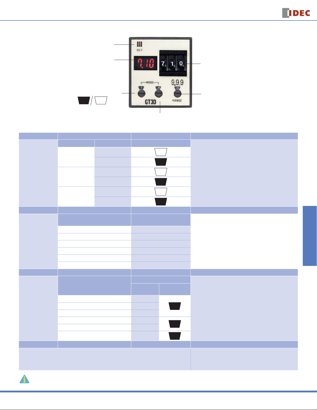
Instructions: Setting GT3D-8 Timers
Timed OUT Indicator
Digital Time Display
(LCD backlit with red LED)
j Indication Mode Selector
1
1
k Operation Mode Selector
A, B, C, D, E, F
Step 1 Desired Mode of Operation Selection Remarks
Operation Mode Time Display Mode
ON-Delay One-Shot
Select the
time display and
operation modes.
Step 2 Desired Mode of Operation Selection Remarks
Select the
single shot output
time.
Step 3 Desired Operation Selection Remarks
Select a time range
that contains the
desired period of time.
Step 4 Desired Operation Selection Remarks
Set the precise period of time desired by using the m Time Setting Digital Switch.
It is important to remember that the l Time Range Selector not only selects the time range but also infl uences the interpretation of the Digital Time Display.
Changing the l Time Range Selector setting changes the units of time measurement (seconds, minutes, hours) as well as the decimal point location.
Cycle One-Shot
ON-Delay One-Shot 2
Desired Single-Shot
Base Time Ranges
0.01 seconds to 9.99 seconds 9.99
0.1 seconds to 99.9 seconds 99.9
1 second to 999 seconds 999
0.1 minutes to 99.9 minutes 99.9
1 minute to 999 minutes 999
0.1 hours to 99.9 hours 99.9
Time elapsed
Time remaining
Time elapsed
Time remaining
Time elapsed
Time remaining
Output Time
0.1 seconds A
0.5 seconds B
1 second C
5 seconds D
10 seconds E
50 seconds F
j Indicator Mode Selector
1
1
2
2
3
3
k Single-Shot Output
Time Selector
l Time Range Selector
Decimal Point
Indicator
Time Increment
Indicator
S
M
H
m Time Setting
Digital Switch
l Time Range Selector
9.99S – 99.9H
1. Use a fl at screwdriver to set the selectors. Since selectors do
not turn all the way around, both clockwise and counterclockwise
rotation is necessary.
2. The GT3D-8 j Indicator Mode Selector selects both whether the
Digital Time Display displays the time elapsed or time remaining
and also the mode of operation. Decide which display and mode is
desired. Then use this selector to set the operation mode.
On the GT3D-8 timers, the desired single-shot output time can be
selected from the A, B, C, D, E, and F modes using the k One-Shot
Output Time Selector.
1. The l Time Range Selector controls both the decimal point indicator (9.99, 99.9, 999) and the time increment indicators S (seconds),
M (minutes), and H (hours).
2. Chose which base time range contains the targeted timer setting.
Then use the l Time Range Selector to set the decimal point indicator and time increment indicator to its corresponding pair of settings.
3. Since these confi gurations offer a complete range of settings
from 0.01 seconds to 99.9 hours, the setting of 9.99 for minutes and
the 9.99 and 999 settings for hours are not listed and should not be
used.
Use the m Time Setting Digital Switch to set the desired period of
time. It is important to remember that the setting of the l Time
Range Selector determines the units of time measurement as well
as the implied decimal point location.
Switches & Pilot Lights Display Lights Relays & Sockets Timers Terminal Blocks
Circuit Breakers
USA: 800-262-IDEC Canada: 888-317-IDEC
825
 Loading...