

Page 1

Timers
GT3A Series
GT3A Series — Analog Timers
Key features of the GT3A series include:
4 selectable operation modes on each model
•
External start, reset, and pause inputs
•
Panel mount or socket mount
•
Large variety of timing functions
•
Power and output status indicating LEDs
•
UL, c-UL Listed
File No. E55996
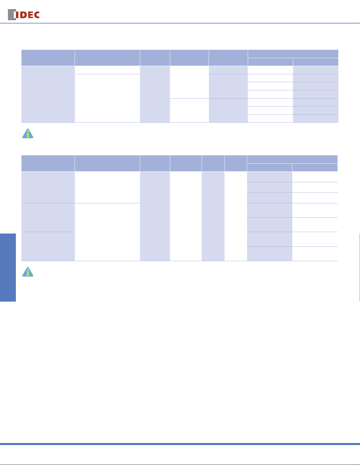
Specifi cations
Operation Multi-mode Multi-mode with inputs (11 pins)
Time Range 0.1s to 180 hours
Rated Voltage
Contact Ratings
Minimum Applicable Load 5V, 10mA (reference value)
Voltage Tolerance
Error ±0.2%, ±10 msec (repeat, voltage, temperature)
Setting Error ±10% maximum
Reset Time 60msec maximum
Insulation Resistance 100MW minimum
Dielectric Strength
Power Consumption
(approximate)
Mechanical Life 10,000,000 operations minimum 5,000,000 operations minimum
Electrical LIfe 50,000 operations minimum (rated load) 100,000 operations minimum (rated load)
Weight (approximate) 63g 73g 79g 80g
Vibration Resistance 100m/sec2 (approximate 10G)
Shock Resistance
Operating Temperature –10 to +50°C
Operating Humidity 45 to 85% RH
Storage Temperature –30 to +80°C
Housing Color Gray
GT3A-1 GT3A-2 GT3A-3 GT3A-4,-5,-6
100 to 240V AC, 50/60Hz
12V DC
24V AC, 50/60Hz / 24V DC
30V DC, 1A (resistive load)
Delayed SPDT
10.8VA
(200V AC, 60Hz)
—
125V AC/250V AC, 3A;
Between power and output terminals: 2,000V AC, 1 minute
Between contacts of different poles: 2,000V AC, 1 minute
instantaneous SPDT
AF20 (100V AC): 85 to 264V AC
AD24: 20.4 to 26.4V AC/21.6 to 26.4V DC
D12: 10.8 to 13.2V DC
Between contacts of the same pole: 750V AC, 1 minute
Delayed SPDT +
13.5VA
(200V AC, 60Hz)
12VDC/1W
24VDC/0.7W
24VAC/1.2VA
Operating extremes: 100m/sec2 (approximate 10G)
Damage limits: 500m/sec2 (approximate 50G)
Delayed DPDT Delayed DPDT
14.4VA
(200V AC, 60Hz)
12VDC/1.1W
24VDC/0.6W
24VAC/1.3VA
125V AC/250V AC, 5A;
30V DC, 5A (resistive load)
4.7VA (100V AC, 60Hz),
14.4VA (200V AC, 60Hz)
12VDC/0.8W
24VDC/0.6W
24VAC/1.3VA
Switches & Pilot Lights Display Lights Relays & Sockets Timers Terminal Blocks
Circuit Breakers
USA: 800-262-IDEC Canada: 888-317-IDEC
805
Page 2
GT3A-1, -2, -3
Operation
A: ON-delay 1
Switches & Pilot LightsDisplay LightsRelays & SocketsTimersTerminal Blocks
B: Interval 1
C: Cycle 1
D: Cycle 3
1. For wiring schematics and timing diagrams for GT3A-1, -2, -3, see pages 807 and 808 respectively.
2. For more details about time ranges, see instructions on page 812.
3. For socket and accessory part numbers, see page 838.
GT3A-4, -5, -6
Operation
A: ON-Delay 2
B: Cycle 2
C: Signal ON/OFF-Delay 1
D: Signal OFF-Delay 1
Mode Of
Mode of
GT3A Series
Rated Voltage Code Time Range Output Contact
AF20: 100 to 240V AC (50/60Hz)
AF20: 100 to 240V AC (50/60Hz)
D12: 12V DC
AD24: 24V AC (50/60Hz)/24V DC
Rated Voltage Code Time Range Output Contact Input
AF20: 100 to 240V AC (50/60Hz)
D12: 12V DC
AD24: 24V AC (50/60Hz)/24V DC
Part Numbers
0.1 seconds
to 180 hours
250V AC, 3A,
30V DC, 1A
(resistive load)
240V AC, 5A,
24V DC, 5A
(resistive load)
Timers
Complete Part No.
8-Pin 11-Pin
Delayed SPDT GT3A-1AF20 GT3A-1EAF20
Delayed SPDT +
Instantaneous SPDT
Delayed DPDT
GT3A-2AF20 GT3A-2EAF20
GT3A-2D12 GT3A-2ED12
GT3A-2AD24 GT3A-2EAD24
GT3A-3AF20 GT3A-3EAF20
GT3A-3D12 GT3A-3ED12
GT3A-3AD24 GT3A-3EAD24
Complete Part No.
A (11-pin) B (11-pin)
GT3A-4AF20 GT3A-4EAF20
GT3A-4D12 GT3A-4ED12
GT3A-4AD24 GT3A-4EAD24
A: Interval 2
B: One-Shot Cycle
C: Signal ON/OFF-Delay 2
D: Signal OFF-Delay 2
A: One-Shot
B: One-Shot ON-Delay
C: One-Shot 2
D: Signal ON/OFF-Delay 3
4. For wiring schematics and timing diagrams GT3A-4,-5,-6, see pages 809, 810, and 811 respectively.
5. For more details about time ranges, see instructions on page 812.
6. A (11-pin) and B (11-pin) differ in the way inputs are wired.
7. For socket and accessory part numbers, see page 838.
8. For the timing diagrams overview, see page 794.
AF20: 100 to 240V AC (50/60Hz)
AD24: 24V AC (50/60Hz)/24V DC
0.1 seconds
to 180 hours
250V AC, 5A,
24V DC, 5A
(resistive load)
Delayed
DPDT
Start
Reset
Gate
GT3A-5AF20 GT3A-5EAF20
GT3A-5AD24 GT3A-5EAD24
GT3A-6AF20 GT3A-6EAF20
GT3A-6AD24 GT3A-6EAD24
Circuit Breakers
806
www.idec.com
Page 3
Timers
GT3A Series
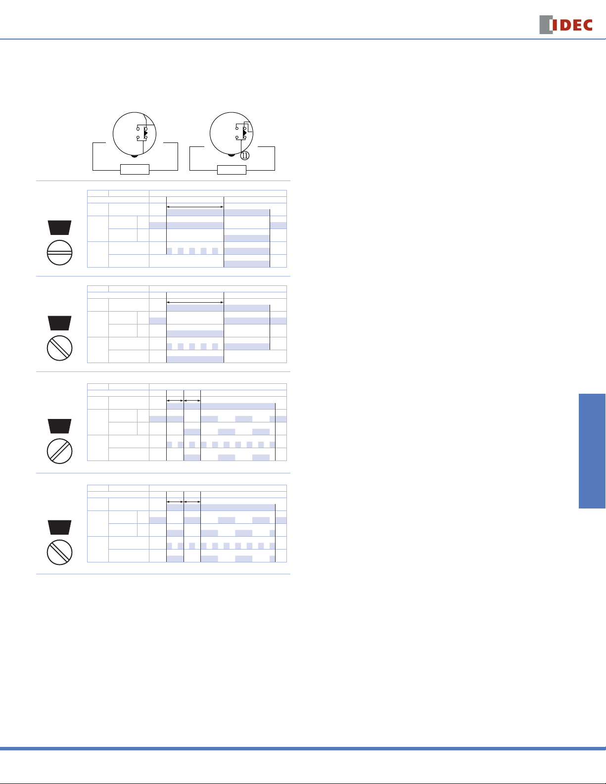
GT3A-1 Timing Diagrams
Delayed SPDT
8-Pin 11-Pin
m
Operation
Mode
Selection
l
k
j
POWER POWER
ON-Delay 1
MODE
A
Interval 1
MODE
B
Item Terminal Number Operation
Set Time T
2 - 7 (8p)
Power
2 - 10 (11p)
5 - 8 (8p)
8 - 11 (11p)
Delayed
Contact
6 - 8 (8p)
9 - 11 (11p)
POWER
Indicator
OUT
Item Terminal Number Operation
Set Time T
2 - 7 (8p)
Power
2 - 10 (11p)
5 - 8 (8p)
8 - 11 (11p)
Delayed
Contact
6 - 8 (8p)
9 - 11 (11p)
POWER
Indicator
OUT
n
q
(NC)
(NO)
(NC)
(NO)
o
p
Timing Diagrams/Schematics
Switches & Pilot Lights Display Lights Relays & Sockets Timers Terminal Blocks
o
p
n
m
l
(+)(-)
k
j
q
s
r
(+)(-)
Cycle 1
(OFF fi rst)
MODE
C
Cycle 3
(ON fi rst)
MODE
D
Item Terminal Number Operation
Set Time TT
2 - 7 (8p)
Power
2 - 10 (11p)
5 - 8 (8p)
(NC)
8 - 11 (11p)
Delayed
Contact
6 - 8 (8p)
(NO)
9 - 11 (11p)
POWER
Indicator
OUT
Item Terminal Number Operation
Set Time TT
2 - 7 (8p)
Power
2 - 10 (11p)
5 - 8 (8p)
(NC)
8 - 11 (11p)
Delayed
Contact
6 - 8 (8p)
(NO)
9 - 11 (11p)
POWER
Indicator
OUT
Circuit Breakers
USA: 800-262-IDEC Canada: 888-317-IDEC
807
Page 4

GT3A Series
Timers
GT3A-2 Timing Diagrams
Delayed SPDT + Instantaneous SPDT
8-Pin 11-Pin
m
Operation
Mode
Selection
Switches & Pilot LightsDisplay LightsRelays & SocketsTimersTerminal Blocks
ON-Delay 1
MODE
A
Interval 1
MODE
B
Cycle 1
(OFF fi rst)
MODE
C
l
k
j
POWER POWER
Item Terminal Number Operation
Set Time T
2 - 7 (8p)
Power
2 - 10 (11p)
5 - 8 (8p)
8 - 11 (11p)
Delayed
Contact
6 - 8 (8p)
9 - 11 (11p)
1 - 4 (NC)
Instantaneous
Contact
1 - 3 (NO)
POWER
Indicator
OUT
Item Terminal Number Operation
Set Time T
2 - 7 (8p)
Power
2 - 10 (11p)
5 - 8 (8p)
8 - 11 (11p)
Delayed
Contact
6 - 8 (8p)
9 - 11 (11p)
1 - 4 (NC)
Instantaneous
Contact
1 - 3 (NO)
POWER
Indicator
OUT
Item Terminal Number Operation
Set Time TT
2 - 7 (8p)
Power
2 - 10 (11p)
5 - 8 (8p)
8 - 11 (11p)
Delayed
Contact
6 - 8 (8p)
9 - 11 (11p)
1 - 4 (NC)
Instantaneous
Contact
1 - 3 (NO)
POWER
Indicator
OUT
n
q
(NC)
(NO)
(NC)
(NO)
(NC)
(NO)
o
p
GT3A-3 Timing Diagrams
Delayed DPDT
o
p
n
m
l
(+)(-)
k
j
q
s
r
Operation
Mode
(+)(-)
Selection
ON-Delay 1
MODE
A
Interval 1
MODE
B
Cycle 1
(OFF fi rst)
MODE
C
Cycle 3
(ON fi rst)
MODE
D
8-Pin 11-Pin
m
l
n
o
n
m
l
k
j
POWER POWER
Item Terminal Number Operation
Set Time T
2 - 7 (8p)
Power
2 - 10 (11p)
1 -4, 5 - 8 (8p)
1 -4, 8 - 11 (11p)
Delayed
Contact
1 -3, 6 - 8 (8p)
1 -3, 9 - 11 (11p)
POWER
Indicator
OUT
Item Terminal Number Operation
Set Time T
2 - 7 (8p)
Power
2 - 10 (11p)
1 -4, 5 - 8 (8p)
1 -4, 8 - 11 (11p)
Delayed
Contact
1 -3, 6 - 8 (8p)
1 -3, 9 - 11 (11p)
POWER
Indicator
OUT
Item Terminal Number Operation
Set Time TT
2 - 7 (8p)
Power
2 - 10 (11p)
1 -4, 5 - 8 (8p)
1 -4, 8 - 11 (11p)
Delayed
Contact
1 -3, 6 - 8 (8p)
1 -3, 9 - 11 (11p)
POWER
Indicator
OUT
Item Terminal Number Operation
Set Time TT
2 - 7 (8p)
Power
2 - 10 (11p)
1 -4, 5 - 8 (8p)
1 -4, 8 - 11 (11p)
Delayed
Contact
1 -3, 6 - 8 (8p)
1 -3, 9 - 11 (11p)
POWER
Indicator
OUT
q
(NC)
(NO)
(NC)
(NO)
(NC)
(NO)
(NC)
(NO)
p
(+)(-)
k
j
o
p
q
s
r
(+)(-)
Circuit Breakers
808
www.idec.com
Page 5

Timers
GT3A Series
GT3A-4 Timing Diagrams
Delayed DPDT
Operation
Mode Selection
Power 2 - 10 POWER
ON-Delay 2
MODE
A
Cycle 2
MODE
B
Signal ON/OFF-Delay 1
MODE
C
Signal OFF-Delay 1
MODE
D
T = Set time Ta = Shorter than set time
T = T' + T"
Input
Delayed
Contact
Indicator
Set Time
Power 2 - 10 POWER
Input
Delayed
Contact
Indicator
Set Time
Power 2 - 10 POWER
Input
Delayed
Contact
Indicator
Set Time
Power 2 - 10 POWER
Input
Delayed
Contact
Indicator
Set Time
(A Type)
(Contact Input)
m
l
k
n
j
POWER
o
p
o
p
n
Reset Start Gate
m
l
k
j
POWER
Item Terminal Number Operation
2 - 6 (A)
Start
Reset
Gate 2 - 5 (A) ON or L
POWER
OUT
Item Terminal Number Operation
Start
Reset
Gate 2 - 5 (A) ON or L
POWER
OUT
Item Terminal Number Operation
Start
Reset
Gate 2 - 5 (A) ON or L
POWER
OUT
Item Terminal Number Operation
Start
Reset
Gate 2 - 5 (A) ON or L
POWER
OUT
1 - 4
8 - 11
1 - 3
9 - 11
1 - 4
8 - 11
1 - 3
9 - 11
1 - 4
8 - 11
1 - 3
9 - 11
1 - 4
8 - 11
1 - 3
9 - 11
5 - 7 (B)
2 - 7 (A)
6 - 7 (B)
2 - 6 (A)
5 - 7 (B)
2 - 7 (A)
6 - 7 (B)
2 - 6 (A)
5 - 7 (B)
2 - 7 (A)
6 - 7 (B)
2 - 6 (A)
5 - 7 (B)
2 - 7 (A)
6 - 7 (B)
ON or L
ON or L
(NC)
(NO)
TTaT'T"
ON or L
ON or L
(NC)
(NO)
TTTTTTTTa TTTT" T"TTTTT
ON or L
ON or L
(NC)
(NO)
T T Ta T Ta T T T T" Ta
ON or L
ON or L
(NC)
(NO)
TTa TaT T T
q
r
s
Reset Start Gate
(+)(-)
q
s
r
(B Type)(Transistor Input)
Start Reset
(+)(-)
m
l
k
n
j
POWER
o
p
q
s
Switches & Pilot Lights Display Lights Relays & Sockets Timers Terminal Blocks
r
(+)(-)
Circuit Breakers
USA: 800-262-IDEC Canada: 888-317-IDEC
809
Page 6

GT3A Series
GT3A-5 Timing Diagrams
Delayed DPDT
(A Type)
(Contact Input)
Timers
(B Type)(Transistor Input)
Operation
Mode Selection
Switches & Pilot LightsDisplay LightsRelays & SocketsTimersTerminal Blocks
Interval 2
One-Shot Cycle
Signal ON/OFF-Delay 2
Signal OFF-Delay 2
Circuit Breakers
T = Set time Ta = Shorter than set time
T = T' + T"
MODE
A
MODE
B
MODE
C
MODE
D
m
l
k
n
j
POWER
o
o
p
n
Reset Start Gate
m
l
k
j
POWER
Item Terminal Number Operation
Power 2 - 10 POWER
2 - 6 (A)
Start
Input
Reset
Gate 2 - 5 (A) ON or L
Delayed
Contact
POWER
Indicator
OUT
Set Time
Item Terminal Number Operation
Power 2 - 10 POWER
Start
Input
Reset
Gate 2 - 5 (A) ON or L
Delayed
Contact
POWER
Indicator
OUT
Set Time
Item Terminal Number Operation
Power 2 - 10 POWER
Start
Input
Reset
Gate 2 - 5 (A) ON or L
Delayed
Contact
POWER
Indicator
OUT
Set Time
Item Terminal Number Operation
Power 2 - 10 POWER
Start
Input
Reset
Gate 2 - 5 (A) ON or L
Delayed
Contact
POWER
Indicator
OUT
Set Time
1 - 4
8 - 11
1 - 3
9 - 11
1 - 4
8 - 11
1 - 3
9 - 11
1 - 4
8 - 11
1 - 3
9 - 11
1 - 4
8 - 11
1 - 3
9 - 11
5 - 7 (B)
2 - 7 (A)
6 - 7 (B)
2 - 6 (A)
5 - 7 (B)
2 - 7 (A)
6 - 7 (B)
2 - 6 (A)
5 - 7 (B)
2 - 7 (A)
6 - 7 (B)
2 - 6 (A)
5 - 7 (B)
2 - 7 (A)
6 - 7 (B)
ON or L
ON or L
(NC)
(NO)
TTaT'T"
ON or L
ON or L
(NC)
(NO)
TT TTa T' T"T
ON or L
ON or L
(NC)
(NO)
T T Ta T Ta Ta T T' T" Ta
ON or L
ON or L
(NC)
(NO)
Reset Start Gate
q
r
s
(+)(-)
T Ta Ta T T' T"
p
q
s
r
Start Reset
(+)(-)
m
l
k
n
j
POWER
o
p
q
s
r
(+)(-)
810
www.idec.com
Page 7

Timers
GT3A Series
GT3A-6 Timing Diagrams
Delayed DPDT
Operation
Mode Selection
Power 2 - 10 POWER
One-Shot 1
MODE
A
One-Shot ON-Delay
MODE
B
One-Shot 2
MODE
C
Signal ON/OFF-Delay 3
MODE
D
T = Set time Ta = Shorter than set time
T = T' + T"
Input
Delayed
Contact
Indicator
Set Time
Power 2 - 10 POWER
Input
Delayed
Contact
Indicator
Set Time
Power 2 - 10 POWER
Input
Delayed
Contact
Indicator
Set Time
Power 2 - 10 POWER
Input
Delayed
Contact
Indicator
Set Time
(A Type)
(Contact Input)
m
l
k
n
j
POWER
o
p
o
p
n
Reset Start Gate
m
l
k
j
POWER
Item Terminal Number Operation
2 - 6 (A)
Start
Reset
Gate 2 - 5 (A) ON or L
POWER
OUT
Item Terminal Number Operation
Start
Reset
Gate 2 - 5 (A) ON or L
POWER
OUT
Item Terminal Number Operation
Start
Reset
Gate 2 - 5 (A) ON or L
POWER
OUT
Item Terminal Number Operation
Start
Reset
Gate 2 - 5 (A) ON or L
POWER
OUT
1 - 4
8 - 11
1 - 3
9 - 11
1 - 4
8 - 11
1 - 3
9 - 11
1 - 4
8 - 11
1 - 3
9 - 11
1 - 4
8 - 11
1 - 3
9 - 11
5 - 7 (B)
2 - 7 (A)
6 - 7 (B)
2 - 6 (A)
5 - 7 (B)
2 - 7 (A)
6 - 7 (B)
2 - 6 (A)
5 - 7 (B)
2 - 7 (A)
6 - 7 (B)
2 - 6 (A)
5 - 7 (B)
2 - 7 (A)
6 - 7 (B)
ON or L
ON or L
(NC)
(NO)
Ta Ta T Ta T' T"
ON or L
ON or L
(NC)
(NO)
T T Ta T T T' T"
ON or L
ON or L
(NC)
(NO)
T Ta T T' T"
ON or L
ON or L
(NC)
(NO)
T T Ta T' T" Ta Ta T
q
r
s
Reset Start Gate
(+)(-)
q
s
r
(B Type)(Transistor Input)
Start Reset
(+)(-)
m
l
k
n
j
POWER
o
p
q
s
Switches & Pilot Lights Display Lights Relays & Sockets Timers Terminal Blocks
r
(+)(-)
Circuit Breakers
USA: 800-262-IDEC Canada: 888-317-IDEC
811
Page 8

GT3A Series
Timers
Instructions: Setting GT3A Series Timers
Timed OUT Indicator
Switches & Pilot LightsDisplay LightsRelays & SocketsTimersTerminal Blocks
j Operator Mode Selector
A, B, C, D
Step 1. Desired Mode of Operation Selection Remarks
For Timers Mode of Operation
GT3A-1
GT3A-2
GT3A-3
GT3A-4
Select the desired mode
of operation.
GT3A-5
GT3A-6
Step 2. Desired Time Range Selection Remarks
0.05 seconds to 1 second 0-1
0.1 seconds to 3 seconds 0-3
0.1 seconds to 6 seconds 0-6
0.15 seconds to 18 seconds 0-18
0.1 seconds to 10 seconds 0-1
0.3 seconds to 30 seconds 0-3
Select the time range
that contains the desired
time period.
Step 3. Selection
Set the precise period of time desired by using the m Setting Knob.
Circuit Breakers
0.6 seconds to 60 seconds 0-6
1.8 seconds to 180 seconds 0-18
6 seconds to 10 minutes 0-1
18 seconds to 30 minutes 0-3
36 seconds to 60 minutes 0-6
108 seconds to 180 minutes 0-18
6 minutes to 10 hours 0-1
18 minutes to 30 hours 0-3
36 minutes to 60 hours 0-6
108 minutes to 180 hours 0-18
ON-delay 1 A
Interval 1 B
Cycle 1 C
Cycle 3 D
ON-delay 2 A
Cycle 2 B
Signal ON/OFF-delay 1 C
Signal OFF-delay 1 D
Interval 2 A
One-shot cycle B
Signal ON/OFF-delay 2 C
Signal OFF-delay 2 D
One-shot 1 A
One-shot ON-delay B
One-shot 2 C
Signal ON/OFF-delay 3 D
Time Ranges
POWER Indicator (fl ashes
during time-delay period)
m Setting Knob
l Time Range Selector
1S, 10S, 10M, 10H
k Dial Selector
0-1, 0-3, 0-6, 0-18
j Operation Mode Selector
k Dial Selector l Time Range Selector
1S
10S
10M
10H
The desired operation mode can be selected from
the A, B, C, and D modes using the Operation Mode
Selector. Change the operation mode from A to B, C,
and D in turn by turning the operation mode selector
clockwise using a fl at screwdriver which is a maximum
of 0.156” (4mm) wide. The selected mode is displayed
in the window.
The desired time range is selected by setting both
k Dial Selector and
l Time Range Selector.
812
www.idec.com
 Loading...