

Page 1
Confirm that the delivered product is what you have ordered. Read this instruction sheet to
make sure of correct operation. Make sure that the instruction sheet is kept by the end
user.
This manual is the instruction sheet of the SmartAXIS Series FT1A Touch.
Unless otherwise specified, SmartAXIS refers to the SmartAXIS Series FT1A Touch.
Touch
The generic term for the SmartAXIS FT1A-*12RA-*, FT1A-*14KA-* and
FT1A-*14SA-*.
SAFETY PRECAUTIONS
● Be certain to read this manual carefully before performing installation, wiring, or
maintenance work, or operating the Touch.
● This product has been manufactured with careful regard to quality. However, if you
intend to use this product in applications where failure of this equipment may result in
damage to property or injury, ensure that it used in conjunction with appropriate fail-safe
backup equipment.
● In this manual, safety precautions are categorized in order of importance to Warning and
Caution:
Warning notices are used to emphasize that improper operation may cause severe
personal injury or death.
Caution notices are used where inattention might cause personal injury or damage to
equipment.
● The Touch is not intended to be used for applications which require high reliability and
safety, such as medical equipment, nuclear equipment, railways, aircraft, and vehicles.
The Touch cannot be used for these applications.
● For other applications which require high reliability in function and precision, provide a
failsafe design and redundant design for the entire system including the Touch.
• Emergency and interlocking circuits must be configured outside of the Touch.
• If relays in the Touch output circuits should fail, outputs may remain at on or off state.
For output signals which may cause serious accidents, configure monitor circuits
outside the Touch.
• The Touch self-diagnostic function may detect internal circuit or program errors, stop
programs, and turn outputs off. Configure circuits so that the system containing the
Touch are not jeopardized when outputs turn off.
1
Page 2

● Emergency and interlocking circuits must be configured outside of the Touch.
Do not use the Touch’s internal touch switches for an emergency circuit. If the Touch
failed, the external equipment connected to the Touch will no longer be protected and
serious injury to operators and equipment damage may be caused.
● Turn off the power to the Touch before installation, removal, wiring, maintenance, and
inspection of the Touch. Failure to turn power off may cause electrical shock or fire
hazard.
● Special expertise is required to install, wire, configure, and operate the Touch. People
without such expertise must not use the Touch.
● The Touch uses an LCD (liquid crystal display) as a display device. The liquid inside the
LCD is harmful to the skin. If the LCD is broken and the liquid attaches to your skin or
clothes, wash the liquid off using soap, and consult a doctor immediately.
● Prevent the Touch from falling while moving or transporting, otherwise damage or
malfunction of the Touch will result.
● Use the product within the environmental limits given in the catalog and manual. Use of
the product in high-temperature or high-humidity environments, or in locations where it
is exposed to condensation, corrosive gas or large shock loads can create the risk of
electrocution and fire.
● The Touch is designed for use in pollution degree 2. Use the Touch in environments of
pollution degree 2. (based on the IEC60664-1 rating)
● Install the Touch according to the instructions in the User’s Manual. Improper installation
will result in falling, failure, electrical shock, fire hazard, or malfunction of the Touch.
● Prevent metal fragments or wire chips from dropping inside the Touch housing. Ingress
of such fragments and chips may cause fire hazard, damage, and malfunction.
● Use a power supply of the rated value. Using a wrong power supply may cause fire
hazard.
● The Touch uses “PS2 of EN61131” as DC power supply. (based on the IEC/EN61131
rating)
● Use wire of a proper size to meet the voltage and current requirements.
● When exporting the Touch to Europe, use an EN60127 (IEC60127) approved fuse on
the power line outside the Touch.
● When exporting the Touch to Europe, use an EU-approved circuit protector.
● Make sure of safety before starting and stopping the Touch. Incorrect operation of the
Touch may cause mechanical damage or accidents.
2
Page 3

● Use the Touch in a local area network if you download, upload or monitor the project
data via the Ethernet port.
● The touch panel of the Touch is made of glass, and will break if exposed to excessive
shock. Take due care when handling it.
● When more than one button is pressed at the same time, due to the detection
characteristics of an analog type touch panel, only the gravity center of the pressed area
is sensed and the unit assumes that only one button is pressed. Thus, when more than
one button is pressed simultaneously, the resulting operation is not guaranteed.
● The screen becomes blank when the backlight is burnt out; however, the touch panel
remains enabled. Incorrect touch panel operation will occur when operating the touch
panel when the backlight appears to be turned off but is actually burnt out. Note that this
erroneous operation may result in damage.
● Do not push hard or scratch the touch panel and protection sheet with a hard object
such as a tool, because they are damaged easily.
● At temperatures over the rated operating temperature, the clock accuracy is affected.
Adjust the clock before use.
● For applications which require clock accuracy, adjust the clock periodically.
● Do not install the Touch in areas subjected to strong ultraviolet rays, since ultraviolet
rays may impair the quality of the LCD.
● Do not attempt to disassemble, repair or modify the Touch. This can create the risk of
fire or electrocution.
● When disposing of the Touch, do so as an industrial waste.
● Do not switch off the power or pull out the USB Flash Drive while it is being accessed, as
this may result in destruction of the stored data. If the data on the USB Flash Drive is
corrupted, format the USB Flash Drive.
3
Page 4

Handling of Batteries and Devices with Built-in Batteries in EU Member States
Note) The following symbol mark is for EU countries only and is according to the directive
2006/66/EC Article 20 information for end-users and Annex II.
This symbol mark means that batteries and accumulators, at their end-of life, should be
disposed of separately from your household waste.
If a chemical symbol is printed beneath the symbol shown above, this chemical symbol
means that the battery or accumulator contains a heavy metal at a certain concentration.
This will be indicated as follows :
Hg : mercury (0.0005%), Cd : cadmium (0.002%), Pd : lead (0.004%)
In the European Union there are separate collection systems for used batteries and
accumulators.
Please dispose of batteries and accumulators correctly in accordance with each country or
local regulation.
4
Page 5

Contents
1 Packing ........................................................................................................ 6
2 Type Number ............................................................................................... 7
3 Part Names ................................................................................................. 8
4 External Interfaces .................................................................................... 10
4.1 Serial Interface (Port) ......................................................................... 10
4.2 I/O Terminals ..................................................................................... 11
4.3 Input Terminal Specifications ............................................................. 13
4.4 Output Specifications ......................................................................... 17
5 Specifications ............................................................................................ 20
6 Dimensions ................................................................................................ 23
7 Installation ................................................................................................. 25
7.1 Operating Environment ...................................................................... 25
7.2 Ambient Temperature ........................................................................ 25
7.3 Installation ......................................................................................... 27
7.4 Orientation ......................................................................................... 28
7.5 Attaching Cartridges .......................................................................... 29
8 Wiring ........................................................................................................ 30
8.1 Power Supply Terminal ...................................................................... 30
8.2 Cautions when connecting external devices ...................................... 31
8.3 Cautions for using the Touch connected to a personal computer ..... 31
9 USB Cable Lock Pin Attachment ............................................................... 32
10 Maintenance and Inspection ..................................................................... 34
10.1 Maintenance Screen .......................................................................... 35
10.2 System Mode ..................................................................................... 35
10.3 Adjusting the Brightness and Contrast .............................................. 36
10.4 Adjusting the Touch Panel ................................................................. 37
5
Page 6
1 Packing
Before installing the Touch, make sure that the specifications of the product conform to
your requirements, and that no parts are missing or damaged due to accidents during
transportation.
Name Pcs/pack
Touch Unit 1
Instruction Sheet [This manual] 1
Mounting clips 2
Power plug
(Attached to the Touch)
Communication I/F plug
(Attached to the Touch)
USB Cable Lock Pin 2
USB Clamp Band 2
1
1
6
Page 7
2 Typ e N um ber
LCD size I/O configuration Bezel color Type No.
Light gray FT1A-M12RA-W
Dark gray FT1A-M12RA-B
Silver FT1A-M12RA-S
Light gray FT1A-M14KA-W
Dark gray FT1A-M14KA-B
Silver FT1A-M14KA-S
Light gray FT1A-M14SA-W
Dark gray FT1A-M14SA-B
Silver FT1A-M14SA-S
Light gray FT1A-C12RA-W
Dark gray FT1A-C12RA-B
Silver FT1A-C12RA-S
Light gray FT1A-C14KA-W
Dark gray FT1A-C14KA-B
Silver FT1A-C14KA-S
Light gray FT1A-C14SA-W
Dark gray FT1A-C14SA-B
Silver FT1A-C14SA-S
3.7inch STN
Monochrome LCD
3.8inch TFT Color
LCD
Digital sink in : 6pt
Shared digital sink in / Analog in : 2pt
Relay out : 4pt
Digital source in : 6pt
Shared digital sink in / Analog in : 2pt
Transisitor sink out : 4pt
Analog out : 2pt
Digital sink in : 6pt
Shared digital sink in / Analog in : 2pt
Transisitor source out : 4pt
Analog out : 2pt
Digital sink in : 6pt
Shared digital sink in / Analog in : 2pt
Relay out : 4pt
Digital source in : 6pt
Shared digital sink in / Analog in : 2pt
Transisitor sink out : 4pt
Analog out : 2pt
Digital sink in : 6pt
Shared digital sink in / Analog in : 2pt
Transisitor source out : 4pt
Analog out : 2pt
7
Page 8
3 Part Names
■ FT1A-*12RA
No. Name Description
(1) Display
(2) Touch Panel
(3) Power Supply Terminal
(4) Serial Interface (Po rt)
(5) Ethernet Interface (Ethernet)
(6) USB Interface (USB 1)
(7) USB Interface (USB 2)
(8) Output Terminal (Q0 to Q3) Relay output (10A)
(9) Input Terminal (I0 to I7) Digital input, Analog input
RS232C, RS422/485
Connector : Terminal Block 9 pin
IEEE802.3u
10BASE-T/100BASE-TX
Connector : RJ-45
USB2.0 (Device)
Connector : Mini-B
USB1.1 (External device)
Connector: TypeA
8
Page 9
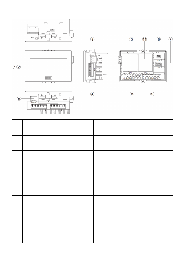
■ FT1A-*14KA/14SA
No. Name Description
(1) Display
(2) Touch Panel
(3) Power Supply Terminal
(4) Serial Interface (Port)
(5) Ethernet Interface (Ethernet)
(6) USB Interface (USB1)
(7) USB Interface (USB2)
(8) Output Terminal (Q0 to Q3, AQ0 to AQ1) Transistor output, analog output
(9) Input Terminal (I0 to I7) Digital input, Analog input
(10) Slot 1
(11) Slot 2
RS232C, RS422/485
Connector : Terminal Block 9 pin
IEEE802.3u
10BASE-T/100BASE-TX
Connector : RJ-45
USB2.0 (Device)
Connector : Mini-B
USB1.1 (External device)
Connector : Type A
Optional product (analog cartridge) expansion
FC6A-PJ2A
FC6A-PK2AV
FC6A-PK2AW
FC6A-PJ2CP
Optional product (analog cartridge) expansion
FC6A-PJ2A
FC6A-PK2AV
FC6A-PK2AW
FC6A-PJ2CP
9
Page 10
4 External Interfaces
● Make sure to turn off the power to the Touch before wiring each interface.
● Always use ferrules when wiring stranded wire and multiple wires to the terminal block.
Otherwise there is a risk of wires becoming disconnected.
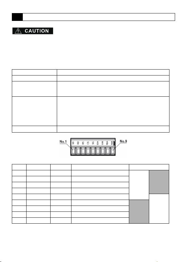
4.1 Serial Interface (Port)
Interface Specification RS232C, RS422/485
Connector Detachable Terminal Block 9 pin
Applicable cable
Recommended ferrule
Tightening Torque
No. Name I/O Function Communication type
1 SD OUT Send Data
2 RD IN Receive Data
3 RS OUT Request to Send
4 CS IN Clear to Send
5 SG - Signal Ground
6 SDA OUT Send Data (+)
7 SDB OUT Send Data (-)
8 RDA IN Receive Data (+)
9 RDB IN Receive Data (-)
<Note>
The Touch is not equipped with terminating resistance. When using the RS422/485
interface, insert terminating resistance with the appropriate value (around 100 to 120 )
between terminal No. 8 (RDA) and terminal No. 9 (RDB) as required.
RS232C: AWG16 to AWG28
RS422/485: AWG16 to AWG28 Shielded twisted-pair
Stripped wire length 7 mm (Solid wire)
AI 0.34-8 TQ (For AWG22)
AI 0.5-8 WH (For AWG20)
AI 0.75-8 GY (For AWG18)
AI 1-8 RD (For AWG18)
AI 1.5-8 BK (For AWG16)
(Phoenix Contact)
0.25 N ·
m
RS232C
10
RS422/485
Page 11
4.2 I/O Terminals
■ FT1A-*12RA
Applicable cable
Recommended ferrule
AWG16 to AWG22
Stripped wire length 6.5 mm, coating diameter 3.4 mm or lower (Solid wire)
AI 0.34-8 TQ (For AWG22, For 1 wire)
AI 0.5-8 WH (For AWG20, For 1 wire)
AI 0.75-8 GY (For AWG18, For 1 wire)
AI 1-10 RD (For AWG18, For 1 wire)
AI 1.5-10 BK (For AWG16, For 1 wire)
AI TWIN 2 x 0.75 10GY (For AWG18, For 2 wires)
(Phoenix Contact)
Tightening Torque 0.5 to 0.6 N•m (Screwdriver SZS 0.6 x 3.5, Phoenix Contact)
■ FT1A-*14KA/14SA
Applicable cable
Recommended ferrule
AWG20 to AWG22
Stripped wire length 5 mm, coating diameter 2.6 mm or lower (Solid wire)
AI 0.34-8 TQ (For AWG22, For 1 wire)
AI 0.5-8 WH (For AWG20, For 1 wire)
AI-TWIN2 x 0.5-8 WH (For AWG20, For 2 wires)
(Phoenix Contact)
Tightening Torque 0.2 N•m (Screwdriver SZS 0.4 x 2.5, Phoenix Contact)
● Terminal Arrangement
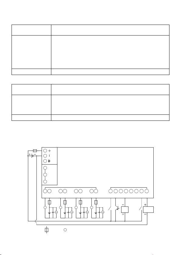
• Terminal Arrangement and I/O Wiring Diagrams
■ FT1A-*12RA
Power supply terminal
1 SD
5 SG
Port
9 RDB
Q0 COM0 Q0 COM0 Q0COM0 Q0COM0
Ry OUT
DC IN
I0 I1 I2 I3 I4 I5 I6 I7
L L L L
:
Fuse
:
Load
L
2-wire
Sensor
Analog voltage
output device
11
Page 12
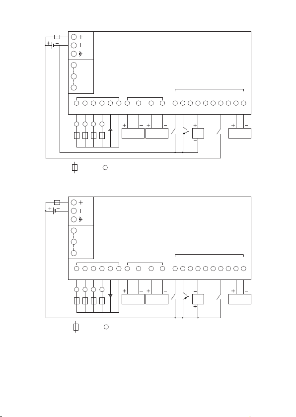
■ FT1A-*14KA
L
: Fuse : Load
Power supply terminal
Q0
LQ1LQ2L
Q3
L
COM
(-)
V
(+)
Tr. OUT Analog OUT
AQ0
(+)
AQ0
(-)
Analog voltage/
current input device
AQ1
(+)
AQ1
(-)
Analog voltage/
current input device
9 RDB
5 SG
1 SD
Port
AI0
(+)
AI0
(-)
AI1
(+)
AI1
(-)
Analog voltage/
current input device
I6 I7
I1 I2 I3 I4 I5I0
2-wire
Sensor
DC IN
■ FT1A-*14SA
Q0
LQ1LQ2L
Power supply terminal
1 SD
5 SG
Port
9 RDB
Tr. OUT Analog OUT
COM
V
Q3
(+)
(-)
L
: Fuse : Load
L
AQ0
AQ0
(+)
(-)
Analog voltage/
current input device
AQ1
AQ1
(+)
(-)
Analog voltage/
current input device
I1 I2 I3 I4 I5I0
2-wire
Sensor
DC IN
AI0
AI0
(+)
(-)
I6 I7
AI1
AI1
(+)
(-)
Analog voltage/
current input device
12
Page 13

4.3 Input Terminal Specifications
Input Points 8
Rated Input Voltage 24V DC
Input Voltage Range 0 to 28.8V DC
Effect of Improper
Input Connection
No damage.
(If any input exceeding the rated value is applied,
permanent damage may be caused.)
● Digital Input Specifications
Input Type
Input Points
(Terminal No. /Common Line Name)
Rated Input Current
Input Impedance
Input System
Transfer Time
Isolation
Input Type Type1 (IEC61131-2)
External Load for I/O Interconnection Not needed
Signal Determination Method Static
Cable Length
(in compliance with EMC standards)
OFF ON 2.5 s + filter value
ON OFF 5 s + filter value
Between input
terminals
Internal circuit Not isolated
Sink (FT1A-*12RA/14SA)
Source (FT1A-*14KA)
6 points in 1 common line
(I0 to I5/Power supply "-" terminal)
4.4mA (Sink Input)
5.2mA (Source Input)
5.5k (Sink Input)
4.7k (Source Input)
Not isolated
3m
● Analog Input Specifications
■ FT1A-*12RA
Input Signal Type Voltage Input
Input Points
(Terminal No. /Common Line Name)
Input Range 0 to 10V DC
Input Impedance 78.0K
Digital Resolution 0 to 1,000 (10bit)
Data Type Binary data: 0 to 1000
Input Value of LSB 10mV
Type of Input Single-ended input
2 points in 1 common line
(I6, I7/internal -terminal, SG terminal for Port)
13
Page 14

Sample Duration Time 2 msec max.
AD Conversion
Input Error
General
Characteristics
Status Display Device Monitor screen (LCD)
Maximum Temporary Error during Electrical
Noise Tests
Recommended Cable for Noise Immunity Twisted pair shielded cable
Calibration or Verification to Maintain Rated
Accuracy
Maximum Permanent Allowed Overload (No
Damage)
Overload Status (Outside Input Range)
Detection
Isolation
Used as Digital
Input
Sample Repetition Time 2 msec max.
Total Input System
Transfer Time
Maximum Error at 25°C ±3.0% of full scale
Temperature Coefficient ±0.04% of full scale/°C
Maximum Error ±5.0% of full scale
Operating Mode Self-scan
Conversion Method type
Between input terminals Not isolated
Between input and
internal circuit
Digit al Input Type — (IEC 61131-2 digital input type is not supported)
Input Threshold
3 msec + filtering time + scan time
±5.0% of full scale
Not possible
28.8V DC
Detectable
Not isolated
ON voltage: 15V min.
(ON current: 0.20 mA min.)
OFF voltage: 5V max.
(OFF current: 0.06 mA max.)
■ FT1A-*14KA/14SA
Input Signal Type Voltage/current input (selectable with software)
Input Points
(Terminal No. /Common Line Name)
Input Range
Input Impedance
Digital Resolution 0 to 1,000 (10bit)
Data Type Binary data: 0 to 1000
Input Value of LSB
Type of Input Single-ended input
1 point in 1 common line
AI0+, AI1+/ AI0-, AI1-
0 to 10V DC (Voltage Input)
4 to 20mA (Current Input)
78.0K (Voltage Input)
250 (Current Input)
10mV (Voltage Input)
16A (Current Input)
14
Page 15

Sample Duration Time 2 msec max.
AD Conversion
Sample Repetition Time 2 msec max.
Total Input System
Transfer Time
3 msec + filtering time + scan time (Voltage Input)
12 msec + filtering time + scan time (Current Input)
Maximum Error at 25°C ±3.0% of full scale
Input Error
Temperature Coefficient ±0.04%/°C of full scale
Maximum Error ±5.0% of full scale
General
Characteristics
Operating Mode Self-scan
Conversion Method SAR
Status Display Device Monitor screen (LCD)
Maximum Temporary Error during Electrical
Noise Tests
±5.0% of full scale
Recommended Cable for Noise Immunity Twisted pair shielded cable
Calibration or Verification to Maintain Rated
Accuracy
Maximum Permanent Allowed Overload (No
Damage)
Overload Status (Outside Input Range)
Detection
Not possible
28.8V DC (Voltage Input)
40mA (Current Input)
Detectable
Between input terminals Not isolated
Isolation
Between input and
internal circuit
Not isolated
Digit al Input Type — (IEC 61131-2 digital input type is not supported)
Used as Digital
Input
Input Threshold
ON voltage: 15V min.
(ON current: 0.20 mA min.)
OFF voltage: 5V max.
(OFF current: 0.06 mA max.)
● Equivalent Circuit
■ FT1A-*12RA
Sink Input (I0 to I5) Shared Digital/Analog Input (I6, I7)
24V DC
24V DC
Input
circuit
4.3kΩ
56kΩ
Input
circuit
1.2kΩ
OV
Internal Circuit
22kΩ
OV
Internal Circuit
15
Page 16

■ FT1A-*14KA
Input
circuit
4.7kΩ
10kΩ
0V
24V DC 24V DC
47kΩ
Internal Circuit
Internal Circuit
Input
circuit
56kΩ
22kΩ
120Ω
130Ω
0V
0V
24V DC
Internal Circuit
Input
circuit
56kΩ
22kΩ
120Ω
130Ω
0V
0V
24V DC
-3.0mA
-6.2mA
Input Current (mA)
5V
15V
24V
Transition Area
ON Area
Input Voltage (V DC)
28.8V
-1.0mA
-5.2mA
OFF Area
Source Input (I0 to I5) Shared Digital/Analog Input (I6, I7)
■ FT1A-*14SA
Sink Input (I0 to I5) Shared Digital/Analog Input (I6, I7)
24V DC
Input
circuit
4.3kΩ
1.2kΩ
OV
● Operating Range
Sink Input (I0 to I5) Source Input
Shared Digital/Analog Input (I6, I7)
Internal Circuit
16
Page 17

4.4 Output Specifications
● Relay Output Specifications
■ FT1A-*12RA
No. of Outputs (Terminal No.) 4 (Q0 to Q3)
Output Type 1a contact
Maximum Load Current 10A
Minimum Switching Load 10 mA/5V DC (reference value)
Initial Contact Resistance 100 m max. (1A, 6V DC)
Electrical Life
Mechanical Life
Rated Load 250V AC/10A, 30V DC/10A
Dielectric
Strength
Status Display Device Monitor screen (LCD display)
Between output terminal
and internal circuit
Between output terminals
(COMs)
100,000 operations min. (rated load 1,800
operations/hour)
20,000,000 operations min. (no load 18,000
operations/hour)
2,300V AC 5mA, 1 minute
Output Delay
17
Page 18

● Transistor Output Specifications
Internal Circuit
COM (+)
Output
V (‒)
■ FT1A-*14KA/14SA
No. of Outputs (Terminal No.) 4 (Q0 to Q3)
Output Type
Sink output (FT1A-*14KA)
Source output (FT1A-*14SA)
Rated Load 24V DC
Operating Load Voltage
Range
20.4 to 28.8V DC
Maximum Load Current 0.3A
Voltage Drop (ON voltage) 1V max. (Voltage between COM and output terminal when ON)
Maximum Inrush Current 1A
Leakage Current 0.1 mA max.
Clamping Voltage 39V ±1V
Maximum Lamp Load 8W
Inductive Load L/R=10 ms (28.8V DC, 1 Hz)
External Current Draw
100 mA max., 24V DC
Sink output: power voltage at the +V terminal
Source output: power voltage at the +COM terminal
Isolation Photocoupler isolate d
Status Display Device Monitor screen (LCD display)
● Equivalent Circuit
■ FT1A-*14KA/14SA
Sink Output (Q0 to Q3) Source Output (Q0 to Q3)
V (+)
Internal Circuit
Output
COM (‒)
18
Page 19

● Analog Output Specifications
■ FT1A-*14KA/14SA
No. of Outputs (Terminal No.) 2 (AQ0 to AQ1)
Output Type Voltage/current output
Output Range
Output Load
D/A
Conversion
Digital Resolution 0 to 1,000 (10bit)
Output Value of LSB
Data Type Binary data: 0 to 1000
Monotonicity Yes
Output Error
Open Current Loop Cannot be detected
*1. Overshoot may occur at light loads.
The occurrence of overshoot can be controlled by inserting damping resistance into the
circuit. A general guide for the damping resistance value is about 150 including the input
line impedance for the destination.
Impedance
Load Type Resistance load
Scan Time 1 scan
Settling Time 1 msec or lower
Total Output System
Transfer Time
Maximum Error at 25°C ±0.3% of full scale
Temperature Coefficient ±0.02%/°C of full Scale
Reproducibility After
Stabilization Time
Non-linearity ±0.01% of full scale
Output Ripple 30 mV max.
Overshoot 0% *1
Maximum Error ±1.0% of full scale
0 to 10 V (Voltage output)
4 to 20 mA (Current output)
2 k min. (Voltage output)
500 max. (Current output)
1 msec + 1 scan
10 mV (Voltage output)
16 A (Current output)
±0.4% of full scale
19
Page 20

Specifications
5
● Applicable Standards
Safety Standard
EMC Standard*1 IEC/EN 61131-2:2007
*1.
When using the Touch as the EMC Standard Approved Products, attach a ferrite core (ZCAT30351330 manufactured by TDK Corporation) to the power cables and the communication cables.
If there a risk of an error occurring due to noise, install the product separated from sources of noise
such as power lines, high voltage lines, and load lines. Also attach a ferrite core to the
I/O cable (ZCAT3035-1330 manufactured by TDK Corporation).
UL508
CSA C22.2 No.142 (c-UL)
● Environmental Specifications
Operating
Temperature*2
Relative 10 to 95% RH (No condensation)
Storage Temperature -20 to +60°C (No freezing)
Storage Humidity 10 to 95% RH (No condensation)
Altitude
Pollution Degree 2
Corrosion Immunity Free from corrosive gases
*2. The UL and c-UL certified operating temperature of the FT1A-*12RA-* is 0 to 50ºC.
0 to 55°C: FT1A-M (Monochrome LCD models)
-20 to 55°C: FT1A-C (Color LCD models) (No freezing)
Operation: 0 to 2,000m
Transport: 0 to 3,000m
● Electrical Specifications
■FT1A-*12RA
Rated Voltage 24V DC
Power Consumption 9.2W max. When USB2 is unused: 5.8W max.
Power Voltage Range 20.4 to 28.8V DC
Allowable Momentary
Power Interruption
Inrush Current 50A max.
Dielectric Strength
10 msec max.
Between power and FE terminals: 500V AC, 5mA,1 minute
Between power and output terminals: 2,300V AC, 5mA, 1 minute
■FT1A-*14KA/14SA
Rated Voltage 24V DC
Power Consumption 11.0W max. When USB2 is unused: 8.1W max.
Power Voltage Range 20.4 to 28.8V DC
Allowable Momentary
Power Interruption
Inrush Current 50A max.
Dielectric Strength
10 msec max.
Between power and FE terminals: 500V AC, 5mA,1 minute
Between power and output terminals: 500V AC, 5mA, 1 minute
20
Page 21

● Construction Specifications
Vibration Resistance
Shock Resistance
5 to 8.4Hz amplitude 3.5mm, 8.4 to 150Hz acceleration 9.8m/s
10 times on each of three mutually perpendicular axes (100 minutes)
(IEC61131-2)
147m/s2, 11ms (5 shocks on each of three mutually perpendicular axes)
(IEC61131-2)
● Performance Specifications
Type Number
LCD Type STN Monochrome LCD TFT Color LCD
Display Colors
Effective Display Area
[mm]
Display Resolution 240 (W) x 100 (H) pixels
View angle Left/Right/Top/Bottom: 45°
Contrast Adjustment 32 levels –
Brightness of LCD only
Brightness Adjustment 32 levels
Backlight
Backlight Life*3 50,000 hours nominal
Display
Switch Type Analog Resistive Film
Operating Force 0.2 to 2.5 N
Multiple Operations Impossible
Life 1,000,000 operations
Touch Panel
User Memory 5MB
Backup Battery*4
Backup Data 128KB
Buzzer Output Single tone (tone length is adjustable)
Degree of Protection IP 66F (IEC60529) *5
FT1A-M
(Monochrome LCD models)
2 Colors (Black, White)
8 shades
87.59(W) × 35.49 (H) 88.92 (W) × 37.05 (H)
White: 740 [cd/m2]
Red: 135 [cd/m2]
LED (White, Red)
Screen color: White, Pink, Red
Lithium secondary battery
Backup Duration: Approx. 30 days (typical) (Operating
temperature: 25°C)
Charging Time: Approx. 15 hours for charging from 0% to 90% of
full charge
Battery Life: 5 years in cycles of 9-hour charging and 15-hour
discharging
Replaceability: Not possible to replace battery
FT1A-C (Color LCD models)
65,536 Colors
Left/Right: 40°, Top: 20°,
Bottom: 60°
400 [cd/m2]
LED (White)
2
21
Page 22

Weight (approx.)
*3. The backlight life refers to the time until the surface brightness reduces to a half after using
continuously at room temperatures.
*4. In high temperature environments battery life may be affected, so retention time may be
reduced.
*5. The degree of protection for the operating section after the panel is attached. The compliance
test has been passed, but this is not a guarantee of operation in all environments.
FT1A-*12RA: 300 g
FT1A-*14KA/SA: 250 g
● EMC Specifications
Type Number FT1A-*12RA FT1A-*14KA/SA
Radiated Emission
Electrostatic Discharge
Electromagnetic Field
Fast Transient Burst
Surge Immunity
Conducted Radio
Frequency Immunity
Class A : 10m
40dBµV/m quasi-peak (30M to 230MHz)
47dBµV/m quasi-peak (230M to 1GHz)
Contact : ±6kV
Air : ±8kV
10V/m (80 to 1000 MHz)
3V/m (1.4 to 2.0 GHz)
1V/m (2.0 to 2.7 GHz)
80% AM (1kHz)
±2kV (Power, Output terminal)
±1kV (Port, Ethernet, Input
terminal)
±500V (between +24V-0V)
±1kV (between +24V-FE, 0V-FE)
10V (Power, Port, Ethernet, Input terminal, Output terminal)
(150kHz to 80MHz)
80% AM (1kHz)
±2kV (Power)
±1kV (Port, Ethernet, Input
terminal, Output terminal)
22
Page 23

Dimensions
6
■ FT1A-*12RA
<Cable Attached Dimensions>
Unit: mm
Depending on the type of connection cable used the dimensions shown above will change.
The dimensions given here are intended for reference only.
23
Page 24

■ FT1A-*14KA/14SA
Unit: mm
77.0
116.0
4.0 54.9
(58.9)
104.5
65.5
<Cable Attached Dimensions>
30
15
20
Depending on the type of connection cable used the dimensions shown above will change.
The dimensions given here are intended for reference only.
50
24
Page 25

7 Installation
Output Current
10A
5A
1A
0
Ambient Temperature
45°C 50°C 55°C
7.1 Operating Environment
For designed performance and safety of the Touch, do not install the Touch in the following
environments:
• Where dust, briny air, or iron particles exist.
• Where oil or chemical splashes for a long time.
• Where oil mist is filled.
• In direct sunlight.
• Where strong ultraviolet rays exist.
• Where corrosive or combustible gasses exist.
• Where the Touch is subjected to shocks or vibrations.
• Where condensation occurs due to rapid temperature change.
• Where high-voltage or arc-generating equipment (electromagnetic contactors or circuit
protectors) exists in the vicinity.
7.2 Ambient Temperature
• Allow sufficient space for ventilation, and install the equipment away from heat sources.
• Allow at least 100mm between the Touch and walls or other equipment.
• Do not install the Touch where the ambient temperature exceeds the rated operating
ambient temperature range. When mounting the Touch in such locations, provide a
forced air-cooling fan or air-conditioner to keep the ambient temperature within the rated
temperature range.
• The Touch is designed to install on a vertical plane so that natural air-cooling is provided.
If you install it using any other orientation, use forced-air cooling, or lower the ambient
operating temperature.
Derating
■ FT1A-*12RA
When using the Touch at an ambient temperature of 45°C or higher, reduce the output
current of each output terminal as shown in the figure below.
Installed upright in landscape orientation
25
Page 26

<Note>
100%
40%
10%
0
30ºC 40ºC 55ºC
Brightness
Ambient Temperature
50ºC
Power Supply Voltage: 20.4 to 24 V
Unit Analog Output: Cannot be used,
Cartridge: Voltage/current output cartridge cannot be used
Power Supply Voltage: 20.4 to 28.8 V
Unit Analog: No restrictions,
Cartridge: No restrictions
If operating the Touch in a high-temperature environment, reducing the brightness of the
backlight can help to limit the temperature rise of internal components.
The relationship between ambient temperature, the output current of each output terminal,
and brightness is approximately as shown in the figure below.
Brightness
100%
50%
0
The values shown above may vary with individual products. Please use this information as
a reference at the time of design.
Output Current10A
Output Current5A
Output Current1A
35°C 45°C 50°C 55°C
Output terminal not used
Ambient Temperature
■ FT1A-*14KA/14SA
When used at ambient temperatures of 40ºC or higher, limit the usage of analog current
output and the analog cartridge as shown in the figure below.
Power Voltage
Range
20.4 to 24V DC
20.4 to 28.8V DC
Touch Analog Output Cartridge
Voltage/current
output cannot be
used
Current output cannot
be used
20.4 to 28.8V DC No restrictions
20.4 to 28.8V DC
Current output cannot
be used
Voltage output (FC6A-PK2AV)/
current output (FC6A-PK2AW)
cannot be used
Voltage output (FC6A-PK2AV)/
current output (FC6A-PK2AW)
cannot be used
Voltage output (FC6A-PK2AV)/
current output (FC6A-PK2AW)
cannot be used
Current output (FC6A-PK2AW)
cannot be used
Operating
Temperature
55ºC
50ºC
45ºC
45ºC
20.4 to 28.8V DC No restrictions No restrictions 40ºC
<Note>
If operating the FT1A-*14KA/14SA in a high-temperature environment, reducing the
brightness of the backlight can help to limit the temperature rise of internal components.
The relationship between ambient temperature and brightness is approximately as shown
in the figure below.
The values shown above may vary with individual products. Please use this information as
a reference at the time of design.
26
Page 27

7.3 Installation
• Make a panel cut-out on the panel with the dimensions shown below.
$
#
• The Touch has the mounting clip positions not only on the top and bottom side (0.3 to
0.35 N
·
m).
TOP
BOTTOM
Mounting Clip Position
A B Panel Cut-out
66.0
+1.0
0
105.0
+1.0
0
Unit: mm
1.0 to 5.0
● Do not tighten excessively, otherwise the Touch may warp and cause wrinkle on the
display, or impair the waterproof characteristics.
● If the mounting clips are tightened obliquely to the panel, the Touch may fall off the
panel.
● When installing the Touch into a panel cut-out, make sure that the gasket is not twisted.
Especially when re-installing, take special care because any twists in the gasket will
impair the waterproof characteristics.
● Even in the panel thickness range, there is a risk that the waterproof characteristics
cannot be maintained due to the panel materials and size.
27
Page 28

7.4 Orientation
The Touch is designed to install on a vertical landscape. If you install it with any other
orientation, confirm the limitations about operating temperature.
Orientation
(Monochrome LCD models)
Landscape
Operating Temperature
FT1A-M
FT1A-C
(Color LCD models)
0 to 55°C
Portrait (Clockwise)
0 to 50°C
Portrait (Counter Clockwise)
0 to 55°C
Vertical
<Note>
• When installing the Touch in a diagonal, the limitations are same as a horizontal.
Horizontal
0 to 50°C
-20 to 55°C
(No freezing)
-20 to 50°C
(No freezing)
-20 to 55°C
(No freezing)
-20 to 50°C
(No freezing)
• Confirm the visibility of the display in a final installation.
28
Page 29

7.5 Attaching Cartridges
Cartridge
Step 1 Insert two flat head screwdrivers into the screwdriver insertion slots in both
locations of the unit, and while pushing the tabs of the cartridge cover, pull the
cartridge cover directly upward to remove it.
Step 2
Pay careful attention to the direction of the cartridge and attach it directly onto the unit.
Screwdriver insertion slot
Screwdriver
insertion slot
Cartridge cover
To remove the cartridge, perform the work detailed in step 1.
● Attach the cartridge directly onto the unit. If the cartridge is attached when tilted, it may
be damaged or cause operating problems.
● Always use ferrules when wiring stranded wire and multiple wires to the terminal block.
Otherwise there is a risk of wires becoming disconnected.
29
Page 30

8 Wiring
● Turn off the power supply before wiring.
● Make the wiring as short as possible and run all wires as far away as possible from
high-voltage and large-current cables. Follow all the procedures and precautions when
wiring the Touch.
● Separate the Touch power supply wiring from the power lines of I/O devices and motor
equipment.
● Ground the functional earth terminal to make sure of correct operation.
● Always use ferrules when wiring stranded wire and multiple wires to the terminal block.
Otherwise there is a risk of wires becoming disconnected.
8.1 Power Supply Terminal
• Pin assignment is shown in the following table.
+ Power supply 24V DC (+24V)
- Power supply 0V (0V)
Functional Earth (FE)
• Use applicable cables for wiring and recommended ferrules (made by Phoenix Contact)
as follows.
Applicable cable
Recommended ferrule
Tightening Torque
AWG16 to AWG22
Stripped wire length 7 mm (Solid wire)
AI 0.34-8 TQ (For AWG22)
AI 0.5-8 WH (For AWG20)
AI 0.75-8 GY (For AWG18)
AI 1-8 RD (For AWG18)
AI 1.5-8 BK (For AWG16)
AI-TWIN 2×0.5-8 WH (For AWG20, TWIN Pressure Terminal)
AI-TWIN 2×0.75-8 GY (For AWG18, TWIN Pressure Terminal)
(Phoenix Contact)
0.5 to 0.6 N ·
m
30
Page 31

8.2 Cautions when connecting external devices
The Touch power supply is non-isolating. Interference or external noise from external
devices due to wiring may cause adverse effects on the internal circuits of the Touch or
external devices.
To prevent such damage, choose a proper solution depending on your system setup.
• Use a separate earth ground from the external noise source device.
• The wire for grounding should be thick and short in order to direct the noise from the
noise source device to the earth ground.
• Use a separate power supply from the external noise source device.
• Insert an isolator on the communication line of the Touch and the non-isolated
communication device (i.e. PLC) to prevent damage.
8.3 Cautions for using the Touch connected to a personal computer
When connecting the Touch to a computer via the Serial Interface (Port) or USB Interface,
the Touch or the computer may break down depending on the conditions of the computer.
Make sure of the following cautions, in order to prevent an accident.
• If the computer has a 3-pin power plug or power plug with a ground lead type.
Make sure to use a plug socket including a ground input electrode or ground the earth
lead, respectively.
• If the computer has a 2-pin power plug without ground lead, follow the procedure below
when connect the Touch to the computer.
(1) Pull out the power plug of the computer from the AC outlet.
(2) Connect the Touch to the computer.
(3) Insert the power plug of the computer into the AC outlet.
31
Page 32

9 USB Cable Lock Pin Attachment
When using the USB interface (USB1, USB2), attach the USB cable lock pin to prevent
disconnecting the USB cable from the Touch.
1 Insert the USB cable into the USB port.
2 Strain the “Edge part” of the USB cable lock pin, and insert the “Edge part” to the 2 holes
upper the USB port.
3 Fasten the USB clamp band around the USB cable and the clamp part, secure them
tightly.
32
Page 33

<Note>
Fasten the USB clamp band without the space between the clamp part and it, and the
inclination.
OK
NG
33
Page 34

10 Maintenance and Inspection
Maintain and inspect the Touch periodically to ensure the best performance. Do not
disassemble, repair, or modify the Touch during inspection.
Wipe any stain of the display using a soft cloth slightly dampened with
Display
Terminals, Connectors
Mounting Clips
Backlight
Touch Panel
neutral detergent or alcoholic solvent.
Do not use solvents such as thinner, ammonia, strong acid, and strong
alkaline.
Check the terminals and connectors to make sure of no loose screws,
incomplete insertion, or disconnected lines.
Make sure that all mounting clips and screws are tightened sufficiently.
If the mounting clips are loose, tighten the screw to the recommended
tightening torque.
The Touch backlight cannot be replaced by the customer.
When the backlight needs to be replaced, contact IDEC.
A gap may be caused in the operation accuracy of the touch panel by
the secular distortion, etc.
Adjust the touch panel according to the following procedure when
there is a gap in the operation of the touch panel.
34
Page 35

10.1 Maintenance Screen
Turn on the power to the Touch, then press and hold the upper-left corner of the screen for
three seconds or longer.
The Maintenance Screen appears on the screen.
Maintenance Screen (Color LCD models) Maintenance Screen (Monochrome LCD models)
• Permission to show the Maintenance Screen can be set using the configuration software.
Refer to the User’s Manual for details.
• The Maintenance Screen is not displayed in the System Mode.
10.2 System Mode
Press the System Mode at the top of the Maintenance Screen. The Top page Screen
appears.
Top Page (Color LCD models) Top Page (Monochrome LCD models)
• Initial Setting, Self Diagnosis and Initialization of the data, etc can be executed in the
System mode.
35
Page 36

10.3 Adjusting the Brightness and Contrast
The brightness and contrast of the Touch display can be adjusted on the Adjust
Brightness/Contrast Screen. Adjust the brightness and contrast to the best condition as
required.
1 Press the Brightness (color LCD models) or Brightness/Contrast (monochrome LCD
models) on the Maintenance Screen.
The Adjust Brightness/Contrast Screen appears.
Color LCD models Monochrome LCD models
2 Press << and >> at the bottom the Adjust Brightness/Contrast Screen to adjust the
contrast to the optimal setting.
Color LCD models Monochrome LCD models
3 Press X to close the Adjust Brightness/Contrast Screen.
To adjust the brightness and Contrast in the System Mode, use << and >> located at the
bottom of the Top Page.
Top Page (Color LCD models) Top Page (Monochrome LCD models)
<Note>
Since contrast adjustment is not possible on color LCD models, the contrast adjust function
is not displayed.
36
Page 37

10.4 Adjusting the Touch Panel
A gap may be caused in the operation accuracy of the touch panel by the secular
distortion, etc. Adjust the touch panel according to the following procedure when there is a
gap in the operation of the touch panel.
1 Press Main Menu on Top Page in System Mode. The Main Menu appears.
Top Page (Color LCD models) Top Page (Monochrome LCD models)
2 Press Init Set, Initialize, and then Touch PnlAdj. The confirmation screen appears and
asks “Touch Panel setting?” is displayed. Press Yes.
The Touch Panel Adjust Screen is displayed.
3 Press the center of the X, then the position of the symbol changes one after another.
Press five symbols sequentially.
<Note>
When pressing the X, make sure to press the center of the symbol. This will ensure the
accuracy of the touch panel operation.
4 When normally recognized, the confirmation screen of 2 is restored.
3, when pressing a point away from the center of the X, a recognition error will
At step
result. Then the X returns to the initial position, then repeat the step of
37
3 again.
 Loading...