

IDEC FT1A Series Programming Manual

FT9Y-B1386(2)
FBD Programming Manual
SAFETY PRECAUTIONS
Warning notices are used to emphasize that improper operation may cause severe personal injury or death.
Warning
Caution notices are used where inattention might cause personal injury or damage to equipment.
Caution
Read the SmartAXIS Pro/Lite User’s Manual and SmartAXIS Touch User's Manual to make sure of correct operation before starting installation,
wiring, operation, maintenance, and inspection of the SmartAXIS.
All SmartAXIS modules are manufactured under IDEC’s rigorous quality control system, but users must add a backup or failsafe provision to the
control system when using the SmartAXIS in applications where heavy damage or personal injury may be caused in case the SmartAXIS should
fail.
In this user’s manual, safety precautions are categorized in order of importance to Warning and Caution:
The SmartAXIS is not designed for use in medical equipment, nuclear power, railways, aviation, passenger vehicle equipment, or similar
applications requiring a high degree of reliability and safety. The SmartAXIS cannot be used for such applications.
When using the SmartAXIS in applications not described above that require a high degree of reliability in terms of functionality and precision,
appropriate measures such as failsafe mechanisms and redundant mechanisms must be taken for a system containing the SmartAXIS.
Emergency stop and interlocking circuits must be configured outside the SmartAXIS.
If relays or transistors in the SmartAXIS output circuits should fail, outputs may remain in the on or off state. For output signals which may
cause serious accidents, configure monitor circuits outside the SmartAXIS.
The SmartAXIS self-diagnostic function may detect internal circuit or program errors, stop programs, and turn outputs off. Configure circuits so
that the system containing the SmartAXIS is not jeopardized when outputs turn off.
Turn off power to the SmartAXIS before installation, removal, wiring, maintenance, and inspection of the SmartAXIS. Failure to turn power off
may cause electrical shocks or fire hazard.
Special expertise is required to install, wire, program, and operate the SmartAXIS. People without such expertise must not use the SmartAXIS.
Install the SmartAXIS according to the instructions described in SmartAXIS Pro/Lite User's Manual and SmartAXIS Touch User's Manual.
Improper installation will result in falling, failure, or malfunction of the SmartAXIS.
The SmartAXIS is designed for installation in a cabinet. Do not install the SmartAXIS outside a cabinet.
Install the SmartAXIS in environments described in SmartAXIS Pro/Lite User's Manual and SmartAXIS Touch User's Manual. If the SmartAXIS is
used in places where the SmartAXIS is subjected to high-temperature, high-humidity, condensation, corrosive gases, excessive vibrations, and
excessive shocks, then electrical shocks, fire hazard, or malfunction will result.
The environment for using the SmartAXIS is “Pollution degree 2.” Use the SmartAXIS in environments of pollution degree 2 (according to IEC
60664-1).
While moving or transporting prevent the SmartAXIS from falling, otherwise damage or malfunction of the SmartAXIS will result.
Wiring must use lead sizes that are appropriate for the applied voltage and current. Terminal screws must be tightened with the prescribed
tightening torque.
Prevent metal fragments and pieces of wire from dropping inside the SmartAXIS housing. Put a cover on the SmartAXIS modules during
installation and wiring. Ingress of such fragments and chips may cause fire hazard, damage, or malfunction.
Use a power supply of the rated value. Use of the wrong power supply may cause fire hazard.
Use an IEC 60127-approved fuse on the power line outside the SmartAXIS. This is required when equipment containing the SmartAXIS is
designed for use in Europe.
Use an IEC 60127-approved fuse on the output circuit. This is required when equipment containing the SmartAXIS is designed for use in Europe.
Use an EU-approved circuit breaker. This is required when equipment containing the SmartAXIS is destined for Europe.
Make sure of safety before starting and stopping the SmartAXIS or when operating the SmartAXIS to force outputs on or off. Incorrect operation
of the SmartAXIS may cause machine damage or accidents.
Do not connect the ground wire directly to the SmartAXIS. Connect a protective ground to the cabinet containing the SmartAXIS using an M4 or
larger screw. This is required when equipment containing the SmartAXIS is designed for use in Europe.
Do not disassemble, repair, or modify the SmartAXIS modules.
The SmartAXIS contains electronic parts and batteries. When disposing of the SmartAXIS, do so in accordance
with national and local regulations.
S
MART
AXIS FBD P
ROGRAMMING MANUAL
FT9Y-B1386 Preface-1

ABOUT THIS MANUAL
IMPORTANT INFORMATION
Under no circumstances shall IDEC Corporation be held liable or responsible for indirect or consequential damages resulting from
the use of or the application of IDEC PLC components, individually or in combination with other equipment.
All persons using these components must be willing to accept responsibility for choosing the correct component to suit their
application and for choosing an application appropriate for the component, individually or in combination with other equipment.
All diagrams and examples in this manual are for illustrative purposes only. In no way does including these diagrams and
examples in this manual constitute a guarantee as to their suitability for any specific application. To test and approve all
programs, prior to installation, is the responsibility of the end user.
This user’s manual describes functions, specifications, installation, and operation basics of the SmartAXIS. Also included is
information on the powerful communications tools of the SmartAXIS, as well as troubleshooting procedures.
Publication history
August 2013 First Edition
October 2013 Second Edition
August 2014 Third Edition
Caution
The contents of this manual and the SmartAXIS and WindLDR applications are copyright, and all rights are reserved by IDEC
Corporation. Unauthorized duplication, reproduction, sales, transfers, or leasing is prohibited.
The contents of this manual and the SmartAXIS and WindLDR applications are subject to change without notice.
Please contact your vendor or IDEC Corporation with any problems regarding the operation of this product.
Trademarks
SmartAXIS is a trademark of IDEC Corporation.
Preface-2 S
MART
AXIS FBD P
ROGRAMMING MANUAL
FT9Y-B1386

RELATED MANUALS
The following manuals related to the SmartAXIS are available. Refer to them in conjunction with this manual.
Type No. Manual Name Description
Describes product specifications, installation and wiring instructions, instructions for
FT9Y-B1378
FT9Y-B1382
FT9Y-B1386
FT9Y-B1390
WindLDR Help
WindO/I-NV3 Help
SmartAXIS Pro/Lite
User’s Manual
SmartAXIS
Ladder Programming Manual
SmartAXIS
FBD Programming Manual
(this manual)
SmartAXIS Touch
User’s Manual
basic programming operations and special functions, device and instruction lists,
communication functions, and troubleshooting procedures for the SmartAXIS Pro/
Lite series.
Describes basic operations for ladder programming, instructions for editing and
monitoring ladders on the SmartAXIS, available devices and instruction lists, and
details of each instruction.
Describes basic operations for function block programming, available devices and
function block lists, and details of each function block.
Describes product specifications, installation and wiring instructions, instructions for
setting basic programming actions and special functions, device and instruction lists,
communication functions, and troubleshooting procedures for the Touch series.
Describes usage instructions for WindLDR, programming software for the SmartAXIS
Pro/Lite series.
Describes programming for the SmartAXIS Touch series, and usage instructions for
the WindO/I-NV3 configuration software.
S
MART
AXIS FBD P
ROGRAMMING MANUAL
FT9Y-B1386 Preface-3

NAMES AND ABBREVIATIONS USED IN THIS MANUAL
Model Names
Name Used in this Manual Description (Detailed Type No.)
SmartAXIS FT1A programmable logic controllers.
Modules without LCD.
SmartAXIS Lite
SmartAXIS Pro
SmartAXIS Touch
12-I/O type
24-I/O type
40-I/O type
48-I/O type
AC power type
DC power type
Touch (Relay output type)
Touch (Transistor output type)
(FT1A-B12RA, FT1A-B12RC, FT1A-B24RA, FT1A-B24RC, FT1A-B40RKA, FT1A-B40RSA, FT1A-B40RC,
FT1A-B48KA, FT1A-B48SA, FT1A-B48KC, FT1A-B48SC)
Modules with LCD.
(FT1A-H12RA, FT1A-H12RC, FT1A-H24RA, FT1A-H24RC, FT1A-H40RKA, FT1A-H40RSA, FT1A-H40RC,
FT1A-H48KA, FT1A-H48SA, FT1A-H48KC, FT1A-H48SC)
Modules that extend the functionality of display.
(FT1A-M12RA-W, FT1A-M12RA-B, FT1A-M12RA-S, FT1A-C12RA-W, FT1A-C12RA-B, FT1A-C12RA-S,
FT1A-M14KA-W, FT1A-M14KA-B, FT1A-M14KA-S, FT1A-C14KA-W, FT1A-C14KA-B, FT1A-C14KA-S,
FT1A-M14SA-W, FT1A-M14SA-B, FT1A-M14SA-S, FT1A-C14SA-W, FT1A-C14SA-B, FT1A-C14SA-S)
SmartAXIS Pro and Lite models with 12 I/O points.
(FT1A-B12RA, FT1A-B12RC, FT1A-H12RA, FT1A-H12RC)
SmartAXIS Pro and Lite models with 24 I/O points.
(FT1A-B24RA, FT1A-B24RC, FT1A-H24RA, FT1A-H24RC)
SmartAXIS Pro and Lite models with 40 I/O points.
(FT1A-B40RKA, FT1A-B40RSA, FT1A-B40RC, FT1A-H40RKA, FT1A-H40RSA, FT1A-H40RC)
SmartAXIS Pro and Lite models with 48 I/O points.
(FT1A-B48KA, FT1A-B48SA, FT1A-B48KC, FT1A-B48SC, FT1A-H48KA, FT1A-H48SA, FT1A-H48KC,
FT1A-H48SC)
SmartAXIS Pro and Lite models with an AC power supply.
(FT1A-B12RC, FT1A-H12RC, FT1A-B24RC, FT1A-H24RC, FT1A-B40RC, FT1A-H40RC, FT1A-B48KC,
FT1A-B48SC, FT1A-H48KC, FT1A-H48SC)
SmartAXIS Pro and Lite models with a DC power supply.
(FT1A-B12RA, FT1A-H12RA, FT1A-B24RA, FT1A-H24RA, FT1A-B40RKA, FT1A-H40RKA,
FT1A-B40RSA, FT1A-H40RSA, FT1A-B48KA, FT1A-B48SA, FT1A-H48KA, FT1A-H48SA)
SmartAXIS Touch with relay output.
(FT1A-M12RA-W, FT1A-M12RA-B, FT1A-M12RA-S, FT1A-C12RA-W, FT1A-C12RA-B, FT1A-C12RA-S)
SmartAXIS Touch with transistor output.
(FT1A-M14KA-W, FT1A-M14KA-B, FT1A-M14KA-S, FT1A-C14KA-W, FT1A-C14KA-B, FT1A-C14KA-S,
FT1A-M14SA-W, FT1A-M14SA-B, FT1A-M14SA-S, FT1A-C14SA-W, FT1A-C14SA-B, FT1A-C14SA-S)
Abbreviations
Abbreviation Meaning
FB
FBD Function block diagram
Function block
For example, the AND (logical AND) function block is described as AND FB.
Preface-4 S
MART
AXIS FBD P
ROGRAMMING MANUAL
FT9Y-B1386

T
ABLE OF
C
HAPTER
C
HAPTER
C
HAPTER
C
HAPTER
1: Operation Basics
2: Basic Operations on the Module
3: Device Addresses
4: FB Reference
C
ONTENTS
Safety Precautions............................................................................................................................. Preface-1
About This Manual............................................................................................................................. Preface-2
Related Manuals................................................................................................................................ Preface-3
Names and Abbreviations Used in this Manual ..................................................................................... Preface-4
Starting WindLDR and PLC Selection ............................................................................................................. 1-1
Creating FBD Program ................................................................................................................................. 1-3
Convert Program ......................................................................................................................................... 1-9
Saving a Project ........................................................................................................................................ 1-10
Simulation ................................................................................................................................................ 1-11
Download Program .................................................................................................................................... 1-12
Monitor Operation ..................................................................................................................................... 1-14
Quit WindLDR ........................................................................................................................................... 1-15
Basic Operations .........................................................................................................................................2-1
Device Addresses ........................................................................................................................................ 3-1
Special Internal Relays.................................................................................................................................3-2
Special Data Registers ................................................................................................................................. 3-6
FB List ........................................................................................................................................................ 4-1
Advanced Instruction Applicable SmartAXIS .................................................................................................. 4-7
Applicable Data Types ................................................................................................................................. 4-8
C
HAPTER
C
HAPTER
C
HAPTER
C
HAPTER
5: The input FB
I (Digital Input) ...........................................................................................................................................5-1
SM (Special Internal Relay) ..........................................................................................................................5-2
R (Shift Register)......................................................................................................................................... 5-3
AI (Analog Input) ........................................................................................................................................ 5-4
6: The output FB
Q (Digital Output)........................................................................................................................................ 6-1
M (Internal Relay) ....................................................................................................................................... 6-2
7: The logical operation FB
AND (Logical AND) ...................................................................................................................................... 7-1
NAND (Negative Logical AND) ...................................................................................................................... 7-2
OR (Logical OR) .......................................................................................................................................... 7-3
NOR (Negative Logical OR) .......................................................................................................................... 7-4
XOR (Exclusive Logical OR) .......................................................................................................................... 7-5
XNOR (Negative Exclusive Logical OR) .......................................................................................................... 7-6
NOT (Negation)........................................................................................................................................... 7-7
SOTU (Shot Up) .......................................................................................................................................... 7-8
SOTD (Shot Down) ...................................................................................................................................... 7-9
TRUTH (Truth Table) ................................................................................................................................. 7-10
8: The timer FB
TIMU (On-delay Count Up Timer) ................................................................................................................. 8-1
TIMD (On-delay Count Down Timer)............................................................................................................. 8-5
TIMOU (Off-delay Count Up Timer)...............................................................................................................8-7
TIMOD (Off-delay Count Down Timer) .......................................................................................................... 8-9
TIMCU (On/off-delay Timer)....................................................................................................................... 8-11
SPULS (Single Shot Pulse) .......................................................................................................................... 8-14
DTIM (Dual Timer) .................................................................................................................................... 8-16
S
MART
AXIS FBD P
ROGRAMMING MANUAL
FT9Y-B1386 I

T
ABLE OF CONTENTS
C
HAPTER
C
HAPTER
C
HAPTER
C
HAPTER
C
HAPTER
C
HAPTER
9: The counter FB
10: The shift register FB
11: The comparison FB
12: The data conversion FB
13: The week programmer FB
14: The interface FB
RPULS (Random Pulse Output) ...................................................................................................................8-19
CNT (Adding Counter) ................................................................................................................................. 9-1
CUD (Up/Down Selection Reversible Counter) ............................................................................................... 9-3
HOUR (Hour Meter) .................................................................................................................................... 9-7
SFR (Shift Register)....................................................................................................................................10-1
CMP (Data Comparison) .............................................................................................................................11-1
STTG (Schmitt Trigger) ..............................................................................................................................11-3
RCMP (Range Comparison) .........................................................................................................................11-5
ALT (Alternate Output) ...............................................................................................................................12-1
WEEK (Weekly Timer) ................................................................................................................................13-1
YEAR (Yearly Timer) ................................................................................................................................ 13-12
MSG (Message)..........................................................................................................................................14-1
C
HAPTER
C
HAPTER
C
HAPTER
C
HAPTER
A
PPENDIX
I
NDEX
15: The pulse FB
PULS (Pulse Output) ..................................................................................................................................15-1
PWM (Pulse Width Modulation) ...................................................................................................................15-6
RAMP (Ramp Pulse Output) ......................................................................................................................15-11
ZRN (Zero Return) ...................................................................................................................................15-21
ARAMP (Advanced Ramp)......................................................................................................................... 15-26
16: The data logging FB
DLOG (Data Log) .......................................................................................................................................16-1
TRACE (Data Trace) ...................................................................................................................................16-8
17: The script FB
SCRPT (Script)...........................................................................................................................................17-1
18: The special FB
HSC (High-speed Counter)..........................................................................................................................18-1
RSFF (RS Flip-flop).....................................................................................................................................18-3
Processing in One Scan ............................................................................................................................... A-1
FBD Program Processing ............................................................................................................................. A-1
Scan End Processing Time ........................................................................................................................... A-1
FB Execution Time ...................................................................................................................................... A-2
FBD Program Size ....................................................................................................................................... A-3
FB Index .................................................................................................................................................... 1-2
II S
MART
AXIS FBD P
ROGRAMMING MANUAL
FT9Y-B1386
1: O
This chapter describes basic instructions for operating WindLDR, software required for programming and maintenance of the
SmartAXIS Pro/Lite series.
Note: SmartAXIS Touch series require WindO/I-NV3 for programming. See the SmartAXIS Touch User's Manual for instructions for programming
and basic operation of WindO/I-NV3 with the Touch series.
PERATION
B
ASICS
Starting WindLDR and PLC Selection
This section describes PLC selection and configuring the programming method.
1. From the Start menu of Windows, select Programs > Automation Organizer V2 > WindLDR > WindLDR.
WindLDR starts.
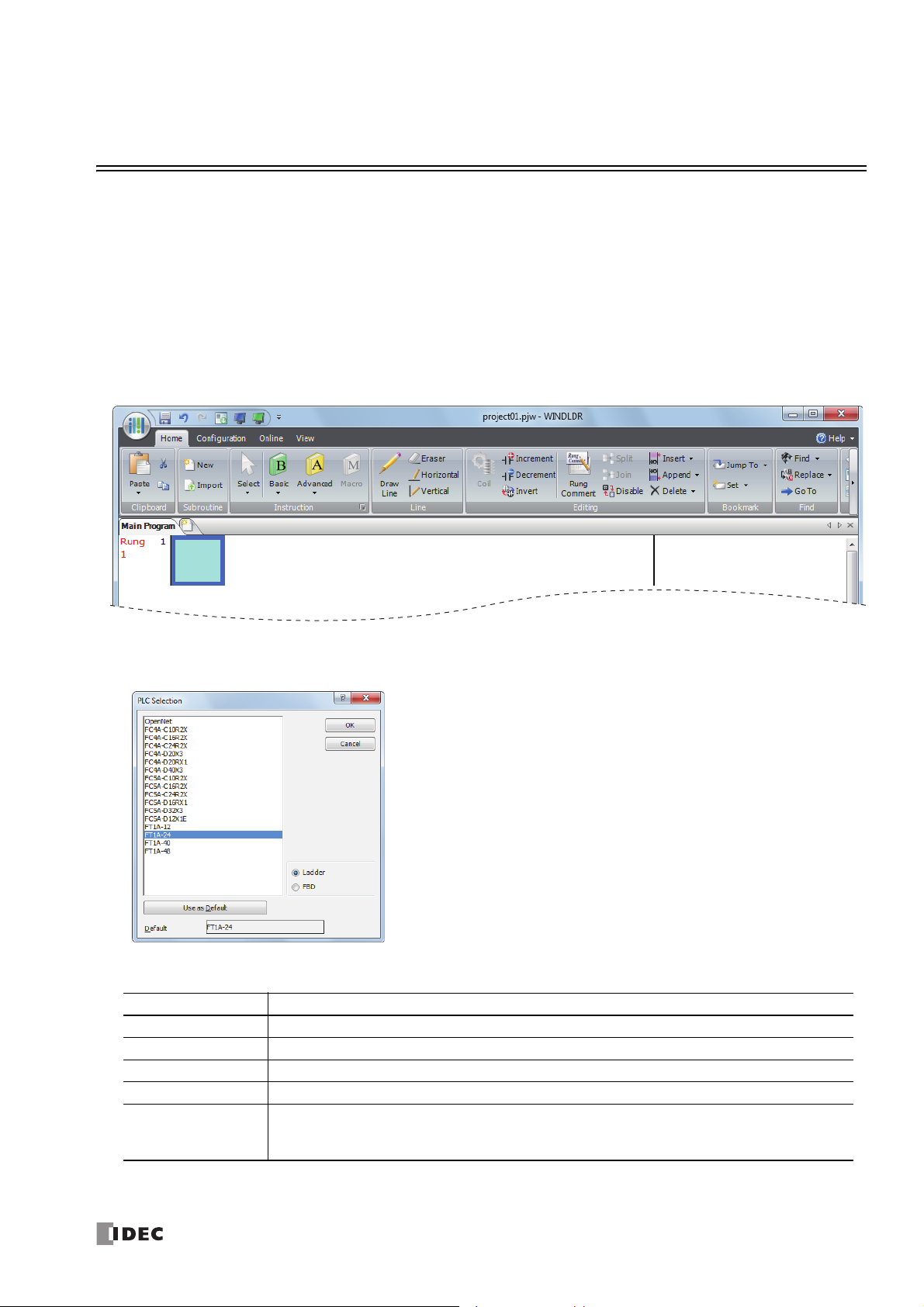
2. From the WindLDR menu bar, select Configuration > PLC > PLC Type.
The PLC Selection dialog box is displayed.
In WindLDR, the SmartAXIS is classified by the number of inputs and outputs, and the names of product series are listed as
follows.
PLC Selection Option SmartAXIS Type No.
FT1A-12 FT1A-H12RA, FT1A-B12RA, FT1A-H12RC, FT1A-B12RC
FT1A-24 FT1A-H24RA, FT1A-B24RA, FT1A-H24RC, FT1A-B24RC
FT1A-40 FT1A-H40RKA, FT1A-H40RSA, FT1A-B40RKA, FT1A-B40RSA, FT1A-H40RC, FT1A-B40RC
FT1A-48 FT1A-H48KA, FT1A-H48SA, FT1A-B48KA, FT1A-B48SA, FT1A-H48KC, FT1A-H48SC, FT1A-B48KC, FT1A-B48SC
FT1A-M12RA-W, FT1A-M12RA-B, FT1A-M12RA-S, FT1A-C12RA-W, FT1A-C12RA-B, FT1A-C12RA-S,
FT1A Touch
If the Use as Default button is pressed, then the same PLC and programming language will be selected as default when
WindLDR is started next time.
FT1A-M14KA-W, FT1A-M14KA-B, FT1A-M14KA-S, FT1A-C14KA-W, FT1A-C14KA-B, FT1A-C14KA-S,
FT1A-M14SA-W, FT1A-M14SA-B, FT1A-M14SA-S, FT1A-C14SA-W, FT1A-C14SA-B, FT1A-C14SA-S
S
MART
AXIS FBD P
ROGRAMMING MANUAL
FT9Y-B1386 1-1
1: O
PERATION BASICS
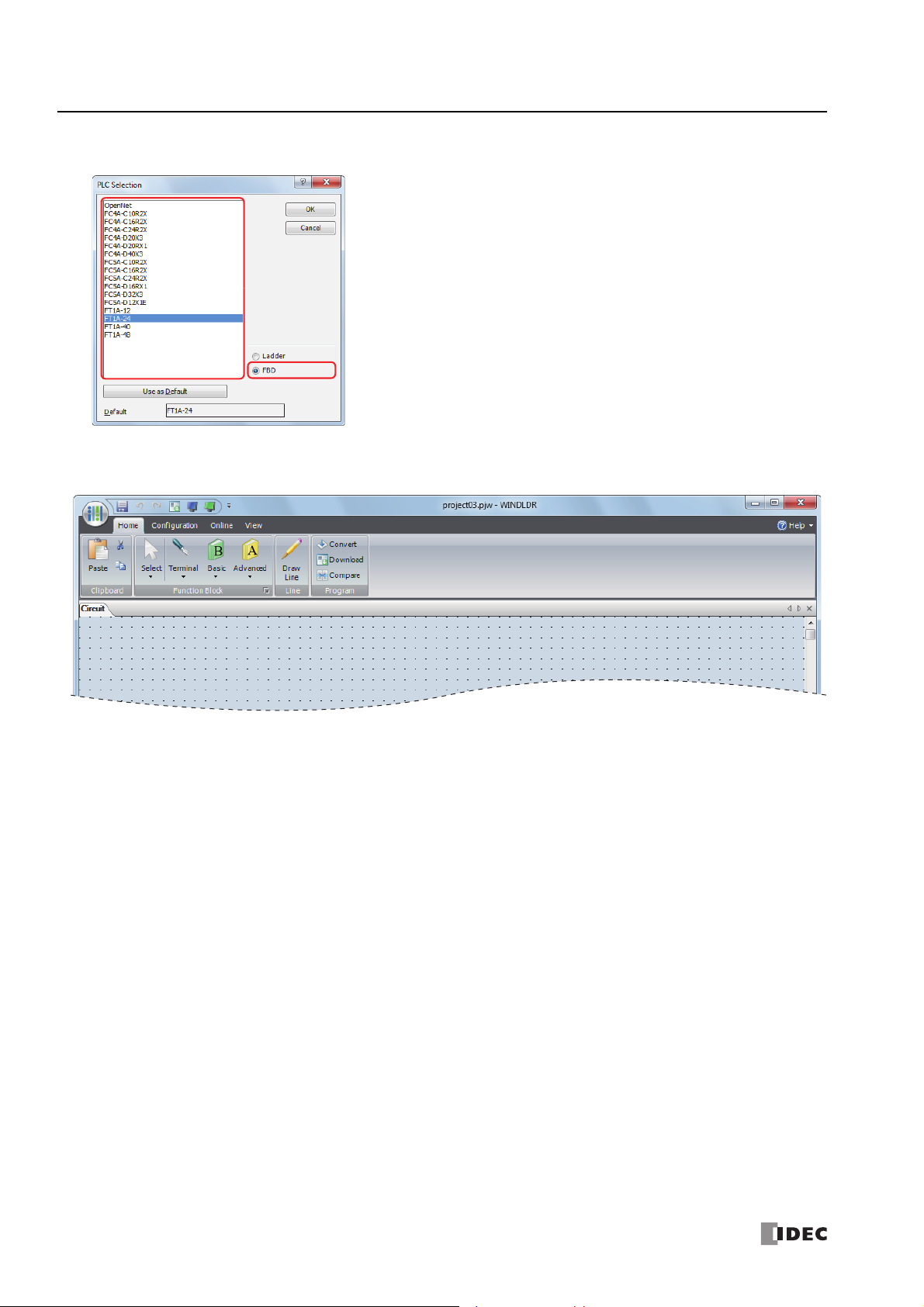
3. Select a PLC type in the selection box, select FBD as the programming language, and click OK.
4. The WindLDR menu bar is updated and the FBD editor opens.
Starting WindLDR and PLC selection are now complete. How to create a FBD program is described in the following pages.
1-2 S
MART
AXIS FBD P
ROGRAMMING MANUAL
FT9Y-B1386
1: O
PERATION BASICS
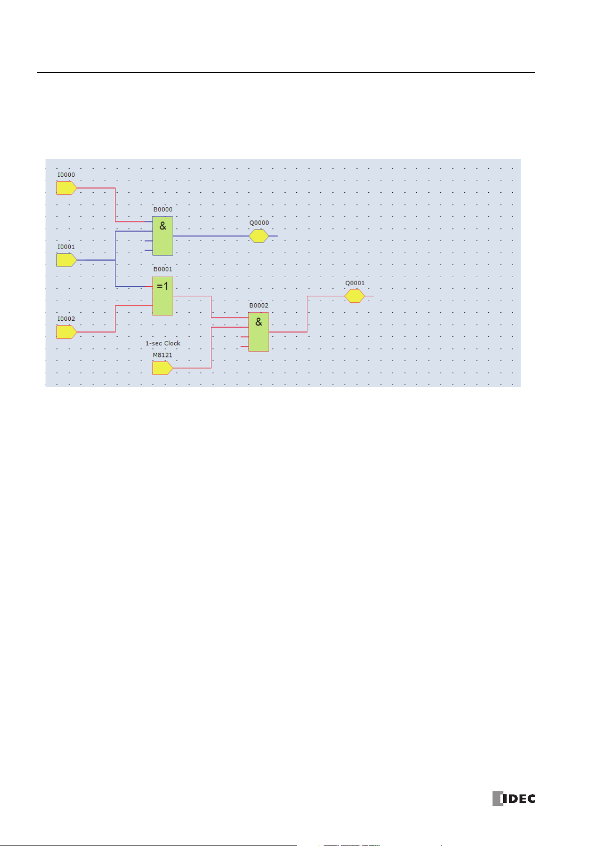
Creating FBD Program
This section describes the procedure for creating a FBD program in WindLDR.
Note: For details about the individual FB, see "FB Reference" on page 4-1.
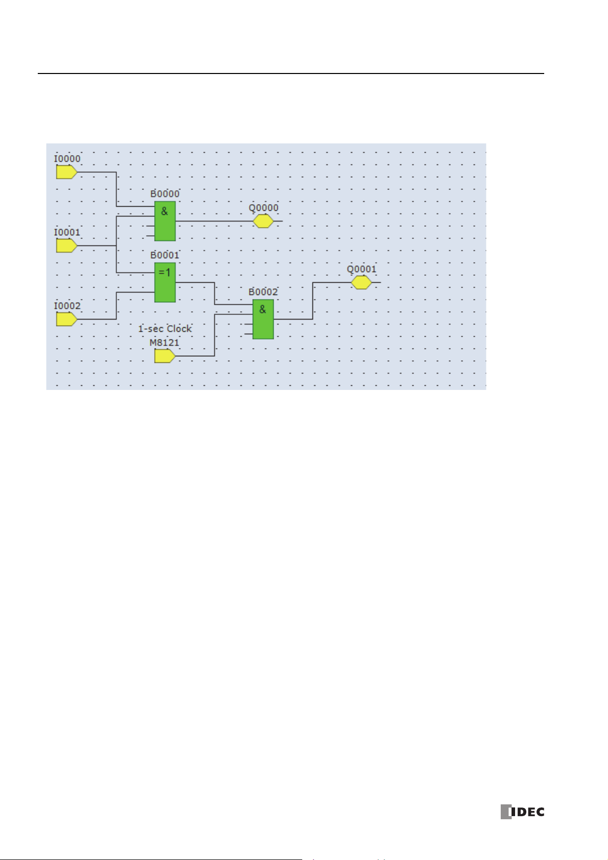
Create a sample program using WindLDR that performs the following operations:
When input I0 and input I1 are both on, output Q0 is turned on.
When either input I1 or input I2 is on, output Q1 turns on and off continuously in one second cycle.
Circuit block Input I0 Input I1 Input I2 Action
Q0 ON ON – Output Q0 is turned on.
Q1
Note: A group of FBs containing an output FB and all FBs connected on the left side of the output FB is called a circuit block. The output of the
output FB is the execution result of a single circuit block.
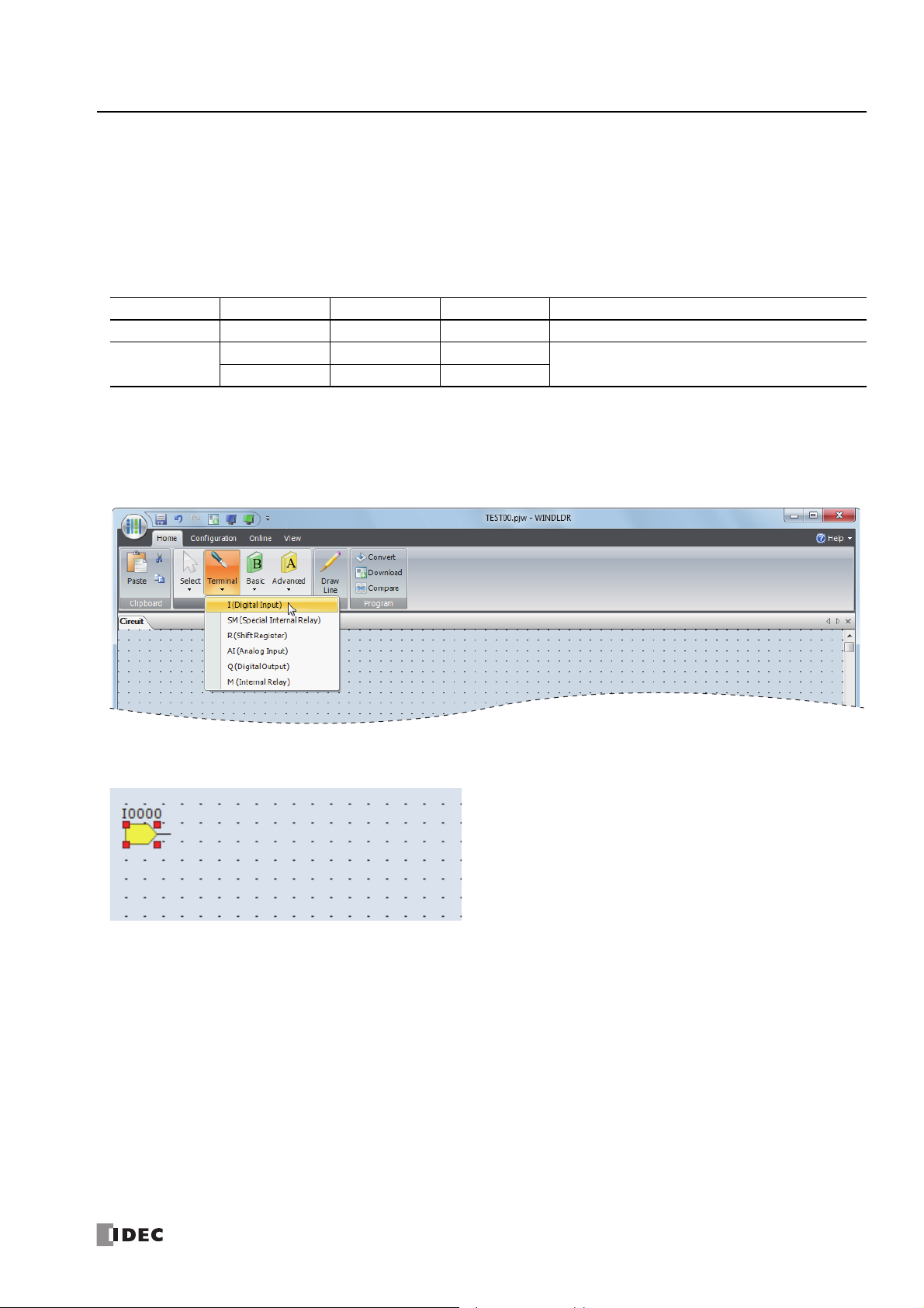
Insert input I0
1. From the WindLDR menu bar, click Home > Function Block > Terminal > I (Digital Input).
–OFFON
–ONOFF
Output Q1 is turned on and off in one second cycle.
2. Move the mouse pointer to the FBD editor and click the left-mouse button.
Input I0 is inserted at the position of the mouse pointer.
S
MART
AXIS FBD P
ROGRAMMING MANUAL
FT9Y-B1386 1-3
1: O
PERATION BASICS
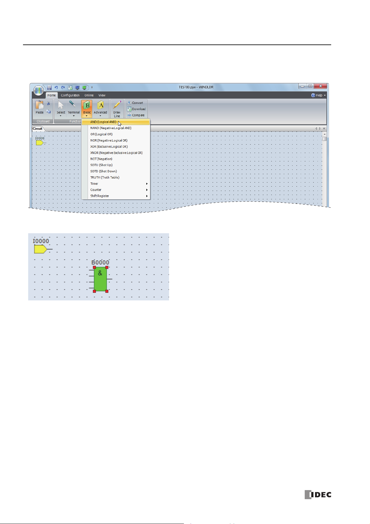
Insert the AND (logical AND) FB
1. From the WindLDR menu bar, click Home > Function Block > Basic >AND (Logical AND).
2. Move the mouse pointer to the FBD editor and click the left-mouse button.
AND B0 is inserted at the position of the mouse pointer.
1-4 S
MART
AXIS FBD P
ROGRAMMING MANUAL
FT9Y-B1386
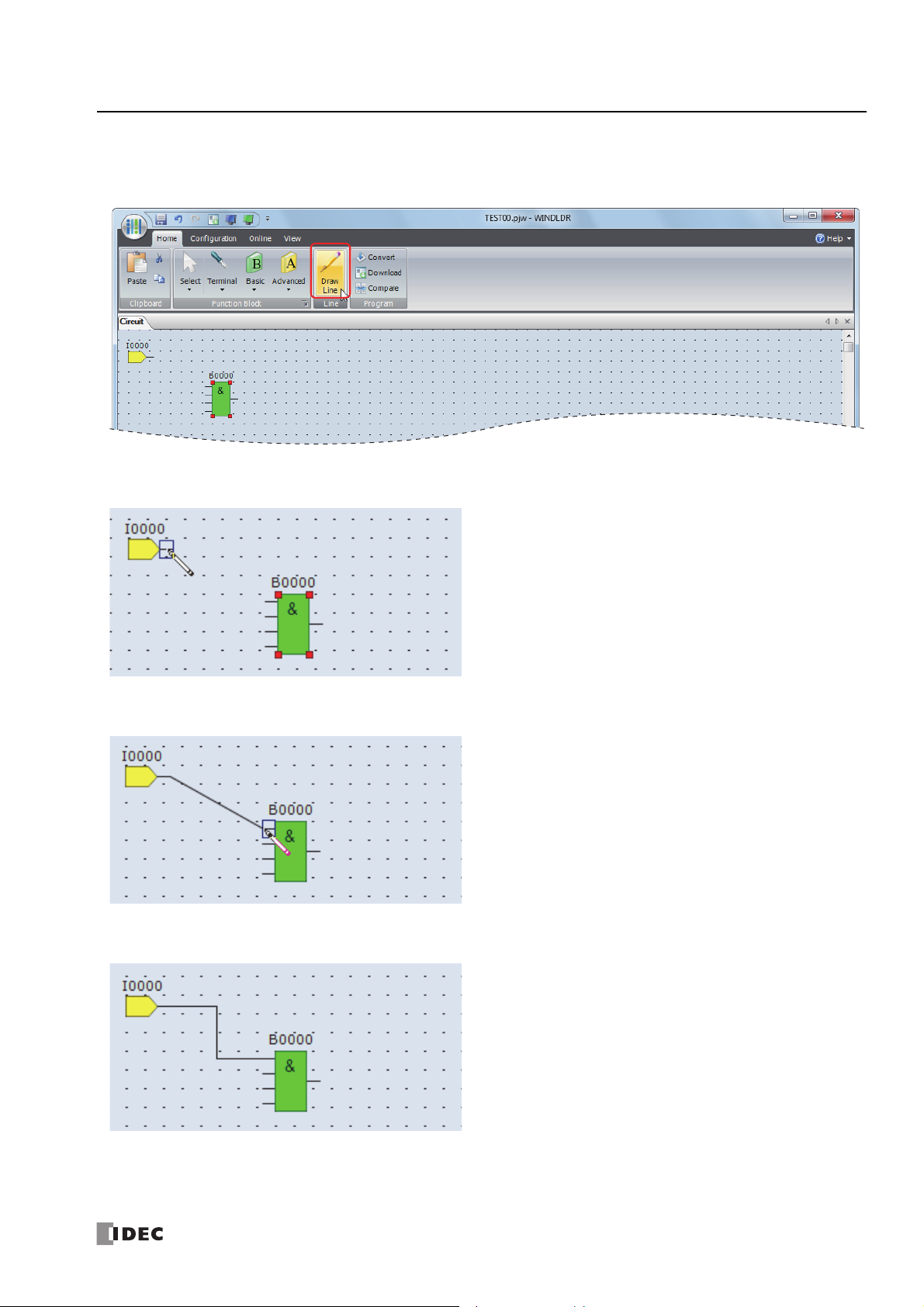
Connect input I0 and AND B0 with a connection line
1. From the WindLDR menu bar, click Home > Line > Draw Line.
2. Move the mouse pointer to the output connector of the input I0.
1: O
PERATION BASICS
3. Click the left-mouse button and drag the line to the input 1 connector of the AND B0.
4. Release the left-mouse button.
The output connector of the input I0 and the input 1 connector of the AND B0 are connected.
S
MART
AXIS FBD P
ROGRAMMING MANUAL
FT9Y-B1386 1-5
1: O
PERATION BASICS
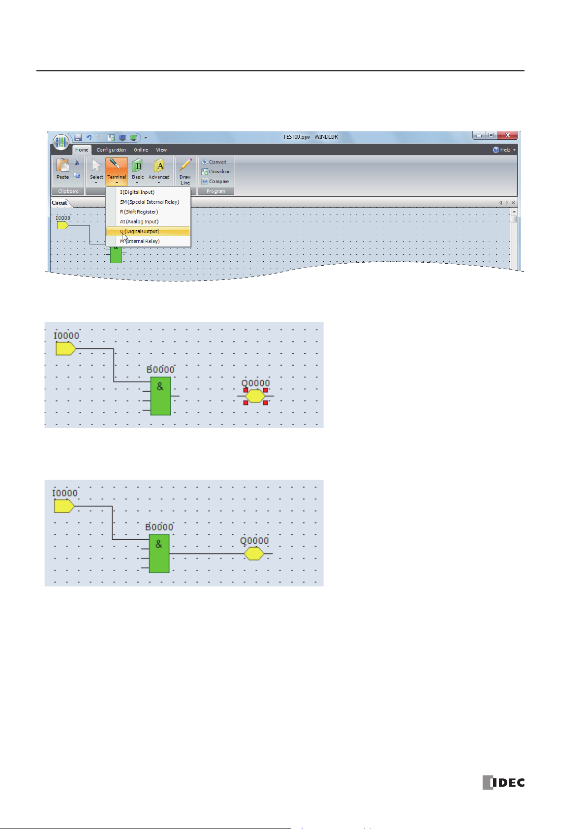
Insert output Q0 and connect it to the output of the AND B0
1. From the WindLDR menu bar, click Home > Function Block > Terminal > Q (Digital Output).
2. Move the mouse pointer to the FBD editor and click the left-mouse button.
Output Q0 is inserted at the position of the mouse pointer.
3. Connect the output connector of the AND B0 and the input connector of the output Q0 with a connection line.
Connect them in the same manner as "Connect input I0 and AND B0 with a connection line" on page 1-5.
1-6 S
MART
AXIS FBD P
ROGRAMMING MANUAL
FT9Y-B1386
1: O
PERATION BASICS
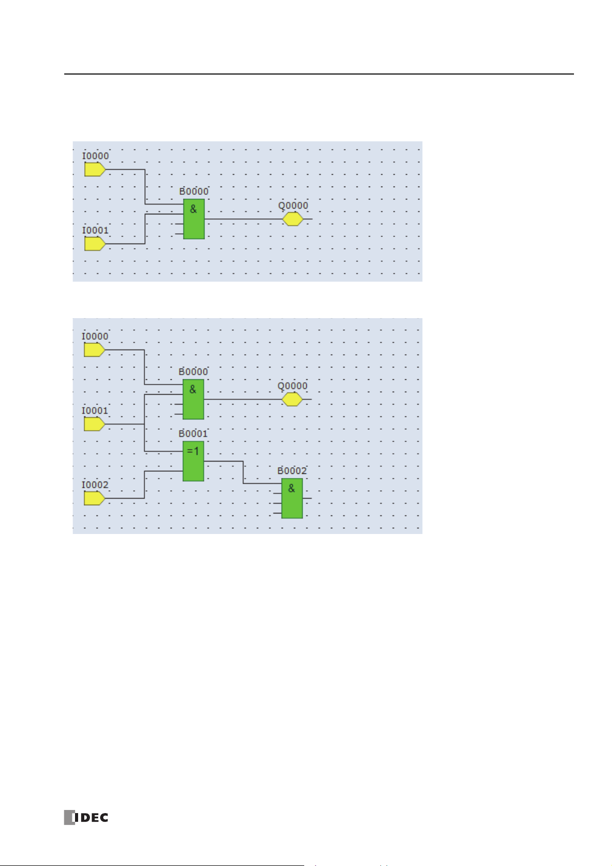
Insert input I1 and connect it to the input 2 of the AND B0
Insert input I1 in the same manner as "Insert input I0" on page 1-3 and connect it to the input 2 of the AND B0 with a connection
line in the same manner as "Connect input I0 and AND B0 with a connection line" on page 1-5.
Insert input I2 and XOR B1 and connect input I1 and input I2 to the inputs 1 and 2 of the XOR FB
Note: A single FB output connector can be connected to multiple FB input connectors. Multiple FB output connectors cannot be connected to a
single FB input connector.
S
MART
AXIS FBD P
ROGRAMMING MANUAL
FT9Y-B1386 1-7
1: O
PERATION BASICS
Insert special internal relay M8121, AND B2, and output Q1 and connect them with connection lines
Note: M8121 is a special internal relay turning on and off continuously in one second cycle. For details on the special internal relay, see "Device
Addresses" - "Special Internal Relays" - "Special Internal Relay Device Addresses" on page 3-2.
Creating FBD program is completed.
1-8 S
MART
AXIS FBD P
ROGRAMMING MANUAL
FT9Y-B1386
1: O
PERATION BASICS
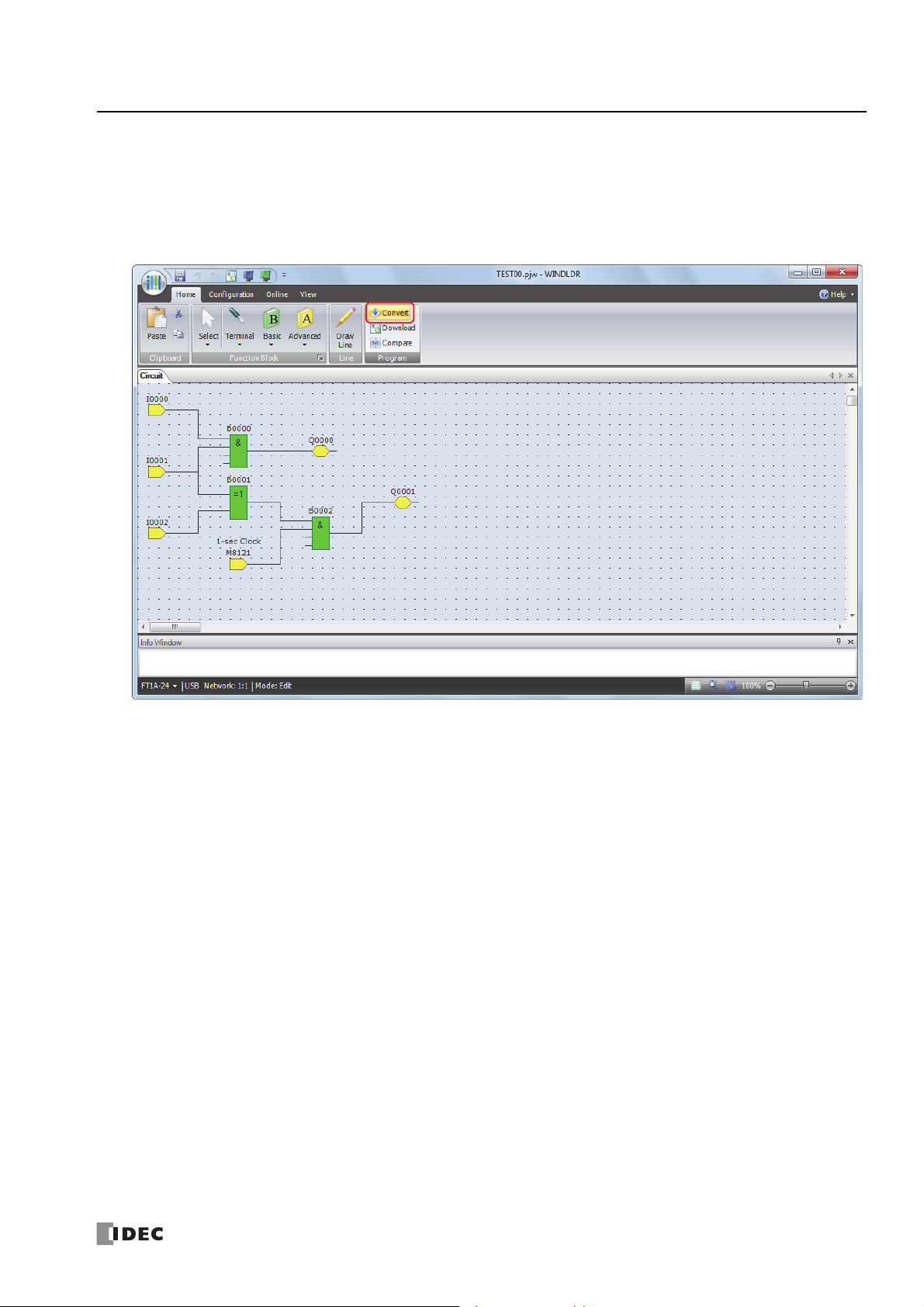
Convert Program
1. Confirm that the program has been correctly created.
From the WindLDR menu bar, click Home > Program > Convert.
If the FBs are correctly connected, the conversion will be successful. If any errors are found, those errors are displayed in the
Info Window. Correct the program to clear those errors in order.
S
MART
AXIS FBD P
ROGRAMMING MANUAL
FT9Y-B1386 1-9
1: O
PERATION BASICS
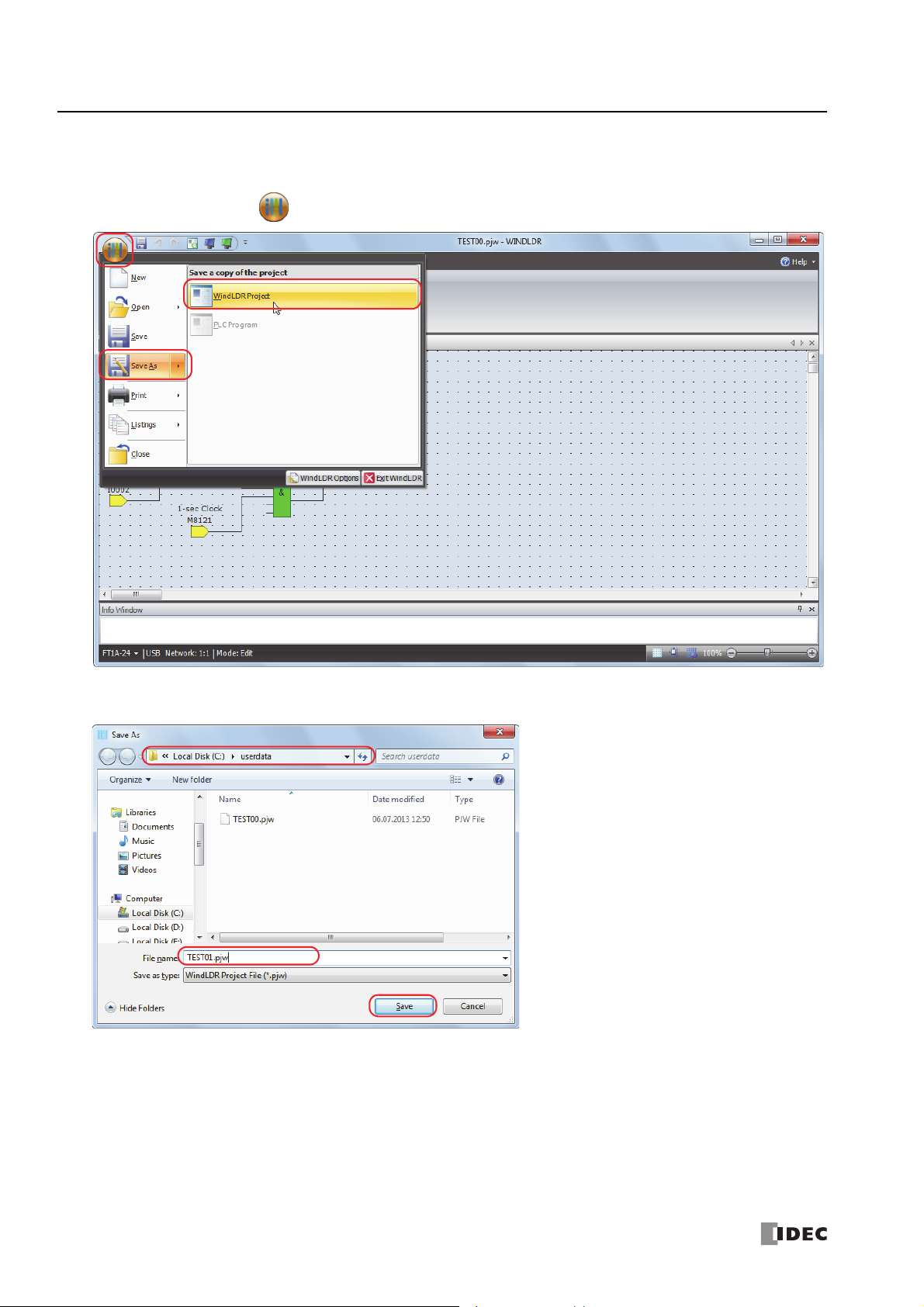
Saving a Project
1. Give the project a name and save it.
From the Application menu , click Save As > WindLDR Project.
2. Specify the project file name as "TEST01.pjw", specify the folder to save to, and click Save.
The project is saved to the specified file.
1-10 S
MART
AXIS FBD P
ROGRAMMING MANUAL
FT9Y-B1386
1: O
PERATION BASICS
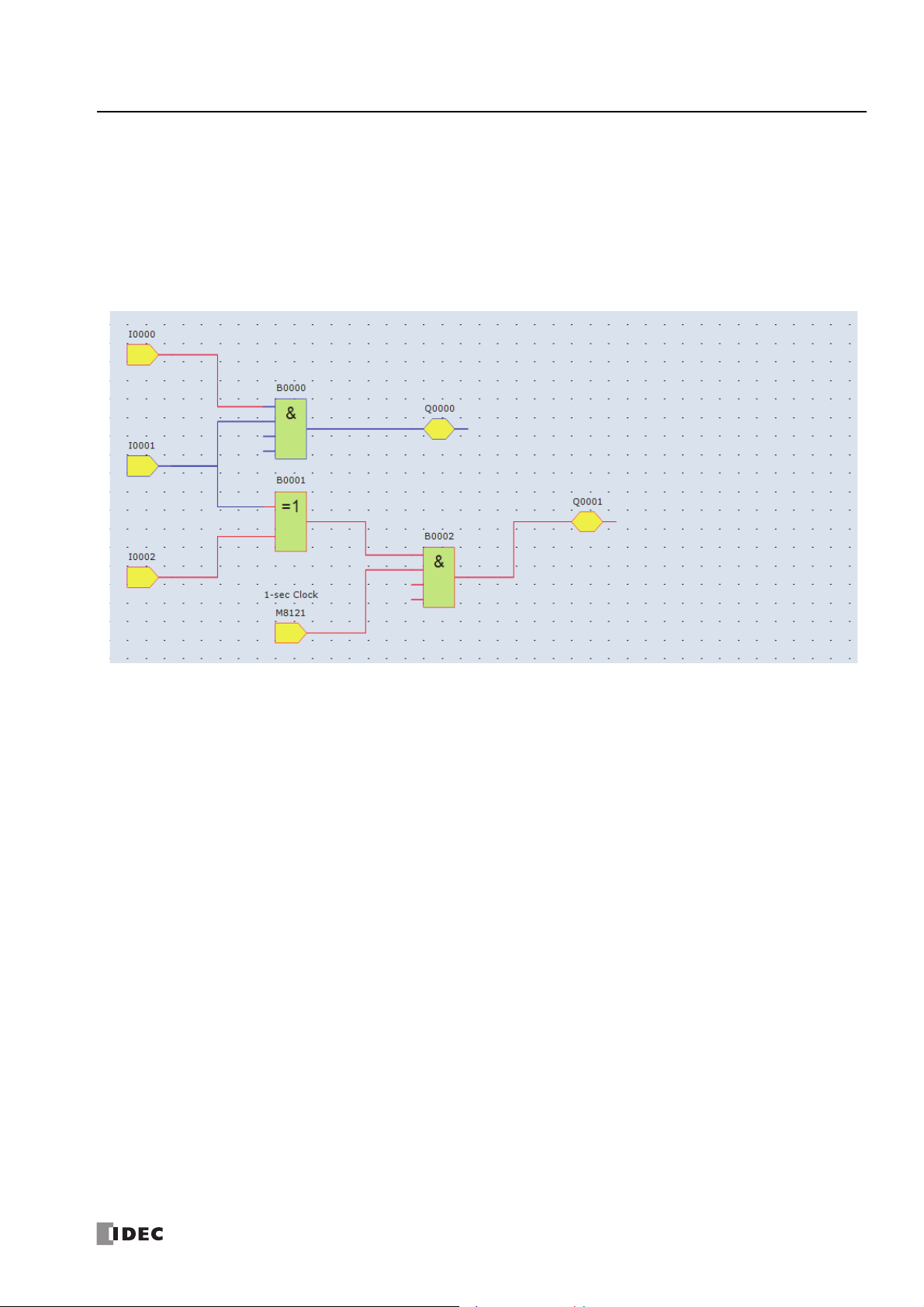
Simulation
Before transferring the user program to the SmartAXIS, you can check the operation of the program in WindLDR. To check
program operation on the SmartAXIS, external devices must be connected to the SmartAXIS and inputs must be turned on and off,
but with the simulation function, input I states can also be changed in WindLDR, which enables you to check the operation of the
program.
1. From the WindLDR menu bar, select Online > Simulation > Simulation.
2. Double-click the input FB you wish to change its state.
When you turn on both input I0 and input I1, output Q0 is turned on.
When you turn on either input I1 or input i2, output Q1 is turned on and off continuously in one second cycle.
Notes:
To end the simulation function, select Online > Simulation > Simulation again.
You can monitor the state of the input connectors and output connectors of each FB. When input connectors, output connectors, and
connection lines are red, they are on. Blue indicates off.
For details on the state of unconnected input connectors of each FB, see the chapters for the FBs.
S
MART
AXIS FBD P
ROGRAMMING MANUAL
FT9Y-B1386 1-11
1: O
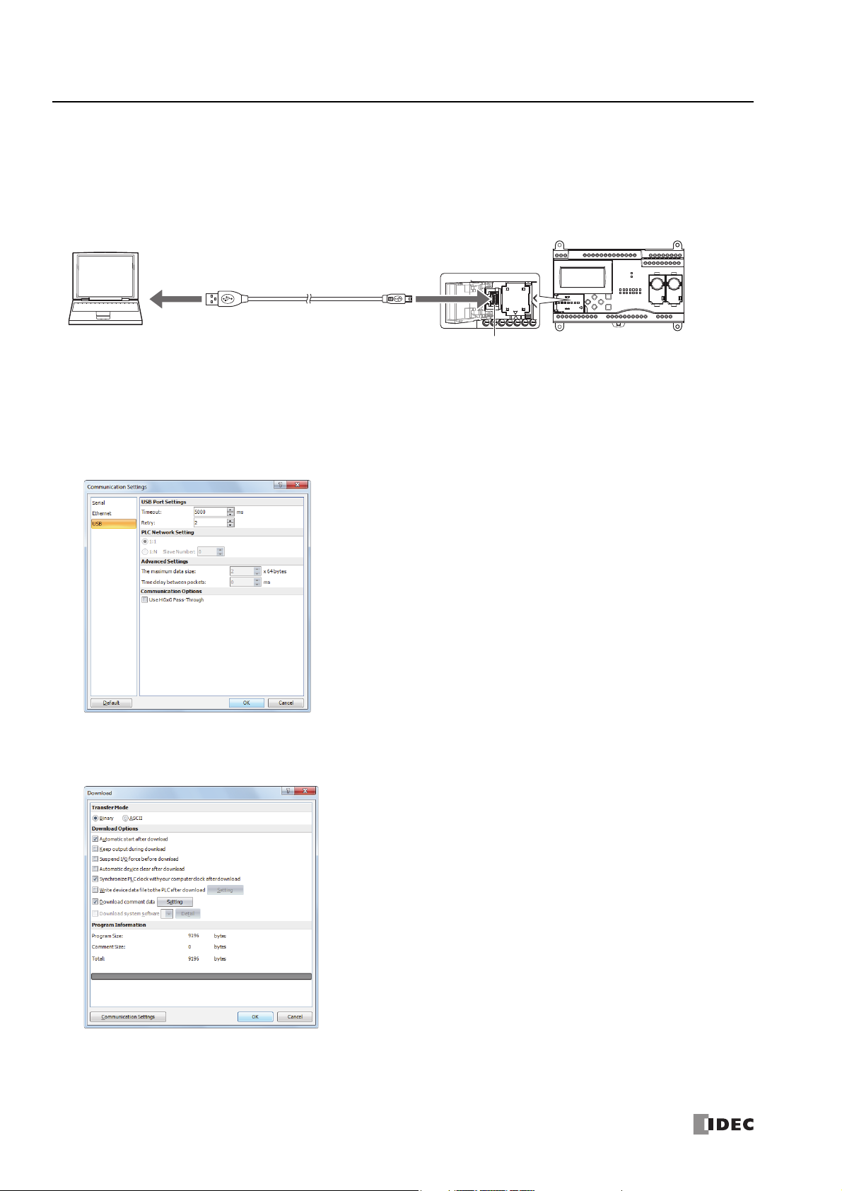
USB port
(USB 2.0 Mini-B connector)
SmartAXIS ProWindows computer
USB port
Type A plug
USB cable
HG9Z-XCM42 USB maintenance cable
Mini-B plug
PERATION BASICS
Download Program
To download a user program to the SmartAXIS, the communication method must be configured in advance.
The user program can be downloaded to the SmartAXIS using WindLDR over a USB connection or an Ethernet connection. This
section describes the procedure, from configuring the communication method to downloading the user program, using a USB
connection as an example.
To use a USB connection, the SmartAXIS USB port must be connected to a computer using a USB cable.
Note: To communicate with the SmartAXIS via a USB connection, the dedicated USB driver must be installed in the computer.
For the driver installation procedure, see "Appendix" in the "SmartAXIS Pro/Lite User's Manual".
Configuration Procedure
1. From the WindLDR menu bar, select Online > Communication > Set Up.
2. The Communication Settings dialog box is displayed. Click the USB tab and then click OK.
The communication method is now set to the USB connection. Next, download a user program.
3. From the WindLDR menu bar, select Online > Transfer > Download > Download.
The Download dialog box is displayed.
The user program is downloaded to the SmartAXIS when you click OK.
Notes:
The created program is downloaded to the SmartAXIS along with the function area settings.
For the function area settings, see Chapter 5 "Special Functions" in the "SmartAXIS Pro/Lite User's Manual".
1-12 S
MART
AXIS FBD P
ROGRAMMING MANUAL
FT9Y-B1386

4. When the following message is displayed, the user program download is successful.
1: O
PERATION BASICS
S
MART
AXIS FBD P
ROGRAMMING MANUAL
FT9Y-B1386 1-13
1: O
PERATION BASICS
Monitor Operation
You can monitor the operations of the downloaded user program using the monitor function of WindLDR.
1. After the user program is successfully downloaded, from the WindLDR menu bar, select Online > Monitor > Monitor.
The SmartAXIS state is displayed on the WindLDR screen.
2. Monitor the following operations.
When you turn on both input I0 and input I1, output Q0 is turned on.
When you turn on either input I1 or input i2, output Q1 is repeatedly turned on and off in one second cycle.
The monitor operation is complete.
Notes:
You can monitor the state of the input connectors and output connectors of each FB. When input connectors, output connectors, and
connection lines are red, they are on. Blue indicates off.
For details on the state of unconnected input connectors of each FB, see the chapters for the FBs.
1-14 S
MART
AXIS FBD P
ROGRAMMING MANUAL
FT9Y-B1386
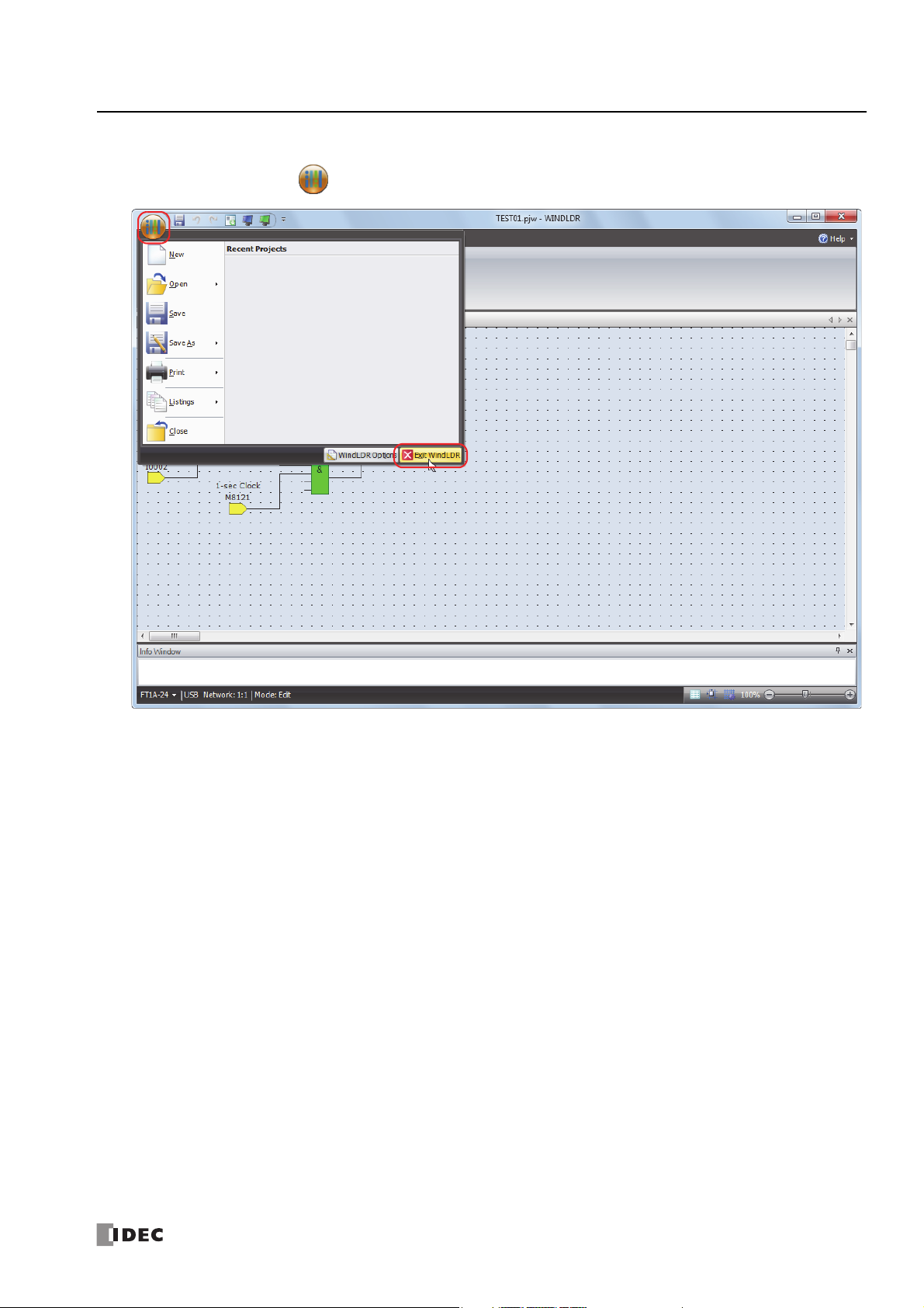
Quit WindLDR
1. From the Application menu , click Exit WindLDR.
1: O
PERATION BASICS
WindLDR exits.
S
MART
AXIS FBD P
ROGRAMMING MANUAL
FT9Y-B1386 1-15

1: O
PERATION BASICS
1-16 S
MART
AXIS FBD P
ROGRAMMING MANUAL
FT9Y-B1386
2: B
RUN
Edit Program
External Memory
Configurations
System menu screen
Operation buttons
RUN
Edit Program
External Memory
Configurations
ASIC
O
PERATIONS ON THE
M
ODULE
Introduction
You can run and stop the SmartAXIS, monitor device values, and modify settings of the SmartAXIS Pro and Touch with the LCD
and operation buttons on the module without using WindLDR. This chapter describes the basic operations of the operation
buttons.
Notes
For other functions of the SmartAXIS Pro, refer to the "SmartAXIS Pro/Lite User’s Manual".
For other functions of the SmartAXIS Touch, refer to the "SmartAXIS Touch User’s Manual".
Applicable SmartAXIS
FT1A-12 FT1A-24 FT1A-40 FT1A-48 FT1A Touch
XXXXX
Basic Operations
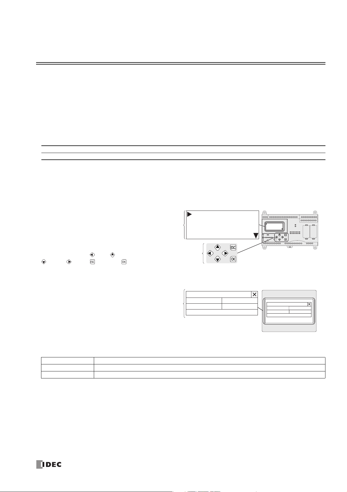
LCD and Operation Buttons
SmartAXIS Pro
The standard screen, the system menu,
and custom messages can be displayed
on the LCD.
The operation buttons are laid out on
SmartAXIS Pro as shown in the diagram
on the right.
A total of six buttons, (left), (up),
(down), (right), (ESC), and
(OK), are available to use.
SmartAXIS Touch
The Touch can be operated using the
buttons displayed on the LCD.
Maintenance Screen
Button Operations
The button operations differ when the button is pressed and released and when the button is pressed and held.
Press/Hold Operation
Press The button is pressed for 0.1 seconds or more and less than 2 seconds and then released.
Press and hold The button is pressed for 2 seconds or more and then released.
Maintenance
System Mode Device Monitor
Brightness
Ladder Start/Stop
Ladder Monitor
Maintenance
System Mode Device Monitor
Brightness
Ladder Start/Stop
Ladder Monitor
S
MART
AXIS FBD P
ROGRAMMING MANUAL
FT9Y-B1386 2-1

2: B
ASIC OPERATIONS ON THE MODULE
2-2 S
MART
AXIS FBD P
ROGRAMMING MANUAL
FT9Y-B1386

3: D
EVICE
A
DDRESSES
Introduction
This chapter describes device addresses available for the SmartAXIS Pro/Lite to program FBD. Special internal relays and special
data registers are also described.
The SmartAXIS is programmed using devices such as inputs, outputs, remote inputs, remote outputs, internal relays, timers,
counters, shift registers, and data registers.
Inputs (I) are relays to receive input signals through the input terminals.
Remote inputs (I) are relays to receive input signals from external devices connected to the remote I/O slaves.
Outputs (Q) are relays to send the processed results of the user program to the output terminals.
Remote outputs (O) are relays to send output signals to external devices connected to the remote I/O slaves.
Internal relays (M) are relays used in the CPU and cannot be output to the output terminals.
Special internal relays (M) are internal relays dedicated to specific functions.
Timers (T) are relays used in the user program, available as 1-sec, 100-ms, 10-ms, and 1-ms timers.
Counters (C) are relays used in the user program, available as adding counter, reversible counter, and hour meter FBs.
Shift registers (R) are registers to shift the data bits according to pulse inputs.
Data registers (D) are registers used to store numerical data.
Special data registers (D) are dedicated to special functions.
Device Addresses
Available I/O numbers depend on the SmartAXIS type.
FT1A-12 FT1A-24 FT1A-40 FT1A-48 FT1A Touch
Device
Input (I)
Remote Input
(I)
Output (Q)
Remote Output
(Q)
Internal Relay
(M)
Special Internal
Relay (M)
Shift Register (R) R0 - R127 128 R0 - R127 128 R0 - R127 128 R0 - R127 128 R0 - R127 128
Timer (T) T0 - T99 100 T0 - T199 200 T0 - T199 200 T0 - T199 200 T0 - T199 200
Counter (C) C0 - C99 100 C0 - C199 200 C0 - C199 200 C0 - C199 200 C0 - C199 200
Data Register
(D)
Special Data
Register (D)
Notes:
*1 The least significant digit of input, output, internal relay, and special internal relay device address is an octal number (0 through 7). Upper digits
*2 Out of data registers D0 through D1999, D1000 through D1999 cannot be designated as "keep" types. Retained in STOPRUN, but cleared
*3 For SmartAXIS Pro/Lite, when you use data register ROM backup, you can initialize the data registers with the values backed up in ROM. For
*1
*1
*1
*1
*1
*1
*3
are decimal numbers.
when the power is turned on.
details, see Chapter 5 "Special Functions" – “Data Register ROM Backup” in the SmartAXIS Pro/Lite User's Manual.
Device
Address
I0 - I7 8
——
Q0 - Q3 4 Q0 - Q7 8
——
M0 - M317 256 M0 - M1277 1024 M0 - M1277 1024 M0 - M1277 1024 M0 - M1277 1024
M8000 - M8177
D0 - D399 400 D0 - D1999*22000 D0 - D1999*22000 D0 - D1999*22000 D0 - D1999 2000
D8000 - D8199
Points
144
200
Device
Address
I0 - I7
I10 - I17
I40 - I75
I80 - I115
I120 - I155
Q40 - Q61
Q80 - Q101
Q120 - Q141
M8000 - M8177
D8000 - D8199
Points
16
90
54
144
200
Device
Address
I0 - I7
I10 - I17
I20 - I27
I40 - I75
I80 - I115
I120 - I155
Q0 - Q7
Q10 - Q17
Q40 - Q61
Q80 - Q101
Q120 - Q141
M8000 - M8177
D8000 - D8199
Points
24
90
16
54
144
200
Device
Address
I0 - I7
I10 - I17
I20 - I27
I30 - I35
I40 - I75
I80 - I115
I120 - I155
Q0 - Q7
Q10 - Q17
Q20, Q21
Q40 - Q61
Q80 - Q101
Q120 - Q141
M8000 - M8177
D8000 - D8199
Points
30 I0 - I7 8
90
18 Q0 - Q3 4
54
144 M8000 - M8177 144
200 D8000 - D8199 200
Device
Address
I40 - I75
I80 - I115
I120 - I155
Q40 - Q61
Q80 - Q101
Q120 - Q141
Points
90
54
S
MART
AXIS FBD P
ROGRAMMING MANUAL
FT9Y-B1386 3-1

3: D
EVICE ADDRESSES
Special Internal Relays
Special internal relays M8000 through M8177 are used for controlling the CPU operation and communication and for indicating CPU
status. All special internal relays cannot be used as destinations of advanced instructions.
Internal relays M300 through M335 are used to read input device status of the IOREF (I/O refresh) instruction.
Note: Do not change the status of reserved special internal relays, otherwise the SmartAXIS may not operate correctly.
Special Internal Relay Device Addresses
Device
Address
M8000 Start Control Maintained Maintained Read/Write
M8001 1-sec Clock Reset Cleared Cleared Write
M8002 All Outputs OFF Cleared Cleared Write
M8003 — Reserved — ―――
M8004 User Program Execution Error Cleared Cleared Read
M8005 Remote I/O Slave 1 Communication Error Operating Cleared Read
M8006 Remote I/O Slave 2 Communication Error Operating Cleared Read
M8007 Remote I/O Slave 3 Communication Error Operating Cleared Read
M8010 In Daylight Saving Time Period (System version 1.10 or later) Operating Cleared Read
M8011-
M8012
M8013 Calendar/Clock Data Write/Adjust Error Flag Operating Cleared Read
M8014 Calendar/Clock Data Read Error Flag Operating Cleared Read
M8015 — Reserved — ―――
M8016 Calendar Data Write Flag Operating Cleared Write
M8017 Clock Data Write Flag Operating Cleared Write
M8020 Calendar/Clock Data Write Flag Operating Cleared Write
M8021 Clock Data Adjust Flag Operating Cleared Write
M8022-
M8024
M8025 Maintain Outputs While CPU Stopped Maintained Cleared Read/Write
M8026 SD Memory Card Status Maintained Cleared Read
M8027 SD Memory Card Writing Flag Maintained Cleared Read
M8030
M8031 Gate Input Maintained Cleared Read
M8032 Reset Input Maintained Cleared Read
M8033 Reset Status Maintained Cleared Read
M8034 Comparison ON Status Maintained Cleared Read
M8035 Overflow Maintained Cleared Read
M8036 Underflow Maintained Cleared Read
M8037 Count Direction Maintained Cleared Read
M8040
M8041 Gate Input Maintained Cleared Read
M8042 Reset Input Maintained Cleared Read
M8043 Comparison ON Status Maintained Cleared Read
M8044 Overflow Maintained Cleared Read
M8045
M8046 Gate Input Maintained Cleared Read
M8047 Reset Input Maintained Cleared Read
M8050 Reset Status Maintained Cleared Read
M8051 Comparison ON Status Maintained Cleared Read
M8052 Overflow Maintained Cleared Read
M8053 Underflow Maintained Cleared Read
M8054 Count Direction Maintained Cleared Read
High-speed Counter (Group 1/I0)
High-speed Counter (Group 2/I2)
High-speed Counter (Group 3/I3)
Description
— Reserved — ―――
— Reserved — ―――
Comparison Output Reset Cleared Cleared Read
Comparison Output Reset Cleared Cleared Read
Comparison Output Reset Cleared Cleared Read
CPU
Stopped
Power OFF Read/Write
3-2 S
MART
AXIS FBD P
ROGRAMMING MANUAL
FT9Y-B1386

3: D
EVICE ADDRESSES
Device
Address
M8055
M8056 Gate Input Maintained Cleared Read
M8057 Reset Input Maintained Cleared Read
M8060 Comparison ON Status Maintained Cleared Read
M8061 Overflow Maintained Cleared Read
M8062-
M8075
M8076 SD Memory Card Access Stop Flag Operating Cleared Write
M8077-
M8087
M8090
M8091 Group 2/I2 Maintained Cleared Read
M8092 Group 3/I3 Maintained Cleared Read
M8093 Group 4/I5 Maintained Cleared Read
M8094 Group 5/I6 Maintained Cleared Read
M8095 Group 6/I7 Maintained Cleared Read
M8096-
M8107
M8110
M8111
M8112
M8113-
M8117
M8120 Initialize Pulse Cleared Cleared Read
M8121 1-sec Clock Operating Cleared Read
M8122 100-ms Clock Operating Cleared Read
M8123 10-ms Clock Operating Cleared Read
M8124 Timer/Counter Preset Value Changed Maintained Cleared Read
M8125 In-operation Output Cleared Cleared Read
M8126-
M8153
M8154
M8155 Read Operating Cleared Read/Write
M8156-
M8157
M8160
M8161 ESC Key + Down Key Cleared Cleared Read
M8162 ESC Key + Left Key Cleared Cleared Read
M8163 ESC Key + Right Key Cleared Cleared Read
M8164
M8165
M8166
M8167 Gate Input Maintained Cleared Read
M8170 Reset Input Maintained Cleared Read
M8171 Comparison ON Status Maintained Cleared Read
M8172 Overflow Maintained Cleared Read
M8173
M8174 Gate Input Maintained Cleared Read
M8175 Reset Input Maintained Cleared Read
M8176 Comparison ON Status Maintained Cleared Read
M8177 Overflow Maintained Cleared Read
High-speed Counter (Group 4/I5)
Catch Input ON/OFF Status
Connection Status
Data Register ROM Backup
Key Input Status
High-speed Counter (Group5/I6)
High-speed Counter (Group 6/I7)
Description
Comparison Output Reset Cleared Cleared Read
— Reserved — ―――
— Reserved — ―――
Group 1/I0 Maintained Cleared Read
— Reserved — ―――
Connection 1
(ON: Connected, OFF: Not Connected)
Connection 2
(ON: Connected, OFF: Not Connected)
Connection 3
(ON: Connected, OFF: Not Connected)
— Reserved — ―――
— Reserved — ―――
Write Operating Cleared Read/Write
— Reserved — ―――
ESC Key + Up Key Cleared Cleared Read
— Reserved — ―――
Comparison Output Reset Cleared Cleared Read
Comparison Output Reset Cleared Cleared Read
CPU
Stopped
Operating Cleared Read
Operating Cleared Read
Operating Cleared Read
Power OFF Read/Write
S
MART
AXIS FBD P
ROGRAMMING MANUAL
FT9Y-B1386 3-3

3: D
EVICE ADDRESSES
M8000 Start Control
M8000 is used to control the operation of the CPU. The CPU stops operation when M8000 is turned off while the CPU is running.
M8000 can be turned on or off using the WindLDR Online menu. When a stop or reset input is designated, M8000 must remain on
to control the CPU operation using the stop or reset input.
M8000 maintains its status when the CPU is powered down. When the data to be maintained during power failure is broken after
the CPU has been off for a period longer than the battery backup duration, the CPU restarts operation or not as selected in
Configuration > Run/Stop Control > Run/Stop Selection at Memory Backup Error. For details, see the following
manuals.
Chapter 5 "Special Functions" - "Run/Stop Selection at Memory Backup Error" in the SmartAXIS Pro/Lite User's Manual
Chapter 3 "Project" - "4 Special Functions" - "4.4 Run/Stop Selection at Memory Backup Error" in the SmartAXIS Touch User's Manual
M8001 1-sec Clock Reset
While M8001 is on, M8121 (1-sec clock) is turned off.
M8002 All Outputs OFF
When M8002 is turned on, all outputs and remote outputs go off until M8002 is turned off. Self-maintained circuits using outputs
also go off and are not restored when M8002 is turned off.
M8004 User Program Execution Error
When an error occurs while executing a user program, M8004 turns on. The cause of the user program execution error can be
checked using Online > Monitor > Monitor, then Online > Status > Error Status > Details.
For a list of user program execution errors, see the following manuals.
Chapter 14 "Troubleshooting" - "User Program Execution Error" in the SmartAXIS Pro/Lite User's Manual
Chapter 30 "Troubleshooting" - "2 Error Information" in the SmartAXIS Touch User's Manual
M8005 Remote I/O Slave 1 Communication Error
When an error occurs during communication with remote I/O slave 1, M8005 turns on. When the error is cleared, M8005 turns off.
M8006 Remote I/O Slave 2 Communication Error
When an error occurs during communication with remote I/O slave 2, M8006 turns on. When the error is cleared, M8006 turns off.
M8007 Remote I/O Slave 3 Communication Error
When an error occurs during communication with remote I/O slave 3, M8007 turns on. When the error is cleared, M8007 turns off.
M8010 In Daylight Saving Time Period
When the daylight saving time is enabled, M8010 is turned on while in the daylight saving time period. When the daylight saving
tiem is disabled, M8010 is always off.
M8013 Calendar/Clock Data Write/Adjust Error Flag
When an error occurs while calendar/clock data is written or clock data is adjusted, M8013 turns on. If calendar/clock data is
written or clock data is adjusted successfully, M8013 turns off.
M8014 Calendar/Clock Data Read Error Flag
When an error occurs while calendar/clock data is read from the internal clock to the special data registers (D8008 to D8014),
M8014 turns on. If calendar/clock data is read successfully, M8014 turns off.
M8016 Calendar Data Write Flag
When M8016 is turned on, data in data registers D8015 through D8018 (calendar new data) are set to the internal clock.
M8017 Clock Data Write Flag
When M8017 is turned on, data in data registers D8019 through D8021 (clock new data) are set to the internal clock.
M8020 Calendar/Clock Data Write Flag
When M8020 is turned on, data in data registers D8015 through D8021 (calendar/clock new data) are set to the internal clock.
M8021 Clock Data Adjust Flag
seconds
When M8021 is turned on, the clock is adjusted with respect to seconds. If
adjustment for
adjustment for
seconds
seconds
will be set to 0 and minutes remain the same. If
will be set to 0 and
minutes
are incremented by one.
seconds
are between 0 and 29 for current time,
are between 30 and 59 for current time,
M8025 Maintain Outputs While CPU Stopped
Outputs are normally turned off when the CPU is stopped. M8025 is used to maintain the output statuses when the CPU is
stopped. When the CPU is stopped with M8025 turned on, the output ON/OFF statuses are maintained. When the CPU restarts,
M8025 is turned off automatically.
3-4 S
MART
AXIS FBD P
ROGRAMMING MANUAL
FT9Y-B1386
3: D
1 scan time
Start
M8120
M8121
500 ms
1 sec
500 ms
M8122
50 ms
100 ms
50 ms
M8123
5 ms
10 ms
5 ms
EVICE ADDRESSES
M8026 SD Memory Card Status
When an SD memory card is inserted into the SmartAXIS, M8026 turns on. When an SD memory card is not inserted, M8026 turns
off.
M8027 SD Memory Card Writing Flag
While logging data is written to the SD memory card, M8027 turns on. When writing logging data is finished, M8027 turns off.
M8030-M8061 Special Internal Relays for High-speed Counter
Special internal relays used for the high-speed counter.
For details on the high-speed counter, see the following manuals.
Chapter 5 "Special Functions" - "High-Speed Counter" in the SmartAXIS Pro/Lite User's Manual
Chapter 3 "4.7 High-Speed Counter" in the SmartAXIS Touch User's Manual
M8076 SD Memory Card Access Stop Flag
Access to the SD memory card stops when M8076 is turned from
off to on.
M8090-M8095 Catch Input ON/OFF Status
When a rising or falling input edge is detected during a scan, the input statuses of catch inputs Group 1/I0 through Group 6/I7 at
the moment are set to M8090 through M8095, respectively, without regard to the scan status. Only one edge is detected in one
scan. For the catch input function, see Chapter 5 "Special Functions" - "Catch Input" in the SmartAXIS Pro/Lite User's Manual.
M8110-M8112 Connection Status
When SmartAXIS and a network device are connected via the maintenance communication server, user communication server/
client, or Modbus TCP server/client, the connection status turns on. When no network devices are connected, the connection
status turns off.
These relays are always off for the 12-I/O type (SmartAXIS without Ethernet port).
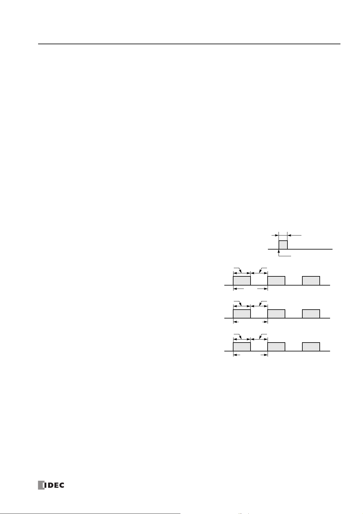
M8120 Initialize Pulse
When the CPU starts operation, M8120 turns on for a period of one scan.
M8121 1-sec Clock
While M8001 (1-sec clock reset) is off, M8121 generates clock
pulses in 1-sec increments, with a duty ratio of 1:1 (500 ms on and
500 ms off).
M8122 100-ms Clock
M8122 always generates clock pulses in 100-ms increments,
whether M8001 is on or off, with a duty ratio of 1:1 (50 ms on and
50 ms off).
M8123 10-ms Clock
M8123 always generates clock pulses in 10-ms increments,
whether M8001 is on or off, with a duty ratio of 1:1 (5 ms on and 5
ms off).
M8124 Timer/Counter Preset Value Changed
When timer/counter preset values are changed in the CPU module RAM, M8124 turns on. When a user program is
downloaded to the CPU from WindLDR or when the changed timer/counter preset value is cleared, M8124 turns off.
When a timer or counter is designated as a destination of an advanced instruction, the timer/counter preset value is also changed.
M8125 In-operation Output
M8125 remains on while the CPU is running.
M8154 Write Data Register values to ROM
This special internal relay is used for the data register ROM backup. When M8154 is on at the end of scan, the values of all data
registers are written to ROM. After writing values, the execution status is stored in D8133 and M8154 turns off. For details, see
Chapter 5 "Special Functions" – "Data Register ROM Backup" in the SmartAXIS Pro/Lite User's Manual.
M8155 In-operation Output
This special internal relay is used for the data register ROM backup. When M8155 turns on at the end of scan, the values in the
corresponding ROM are read and stored in the data registers specified by D8184 (start address to read) and D8185 (number of
registers to read). After reading values, the execution status is stored in D8133 and M8155 turns off. For details, see Chapter 5
"Special Functions" – "Data Register ROM Backup" in the SmartAXIS Pro/Lite User's Manual.
S
MART
AXIS FBD P
ROGRAMMING MANUAL
FT9Y-B1386 3-5
 Loading...