


FT9Y-B1378(5)


SAFETY PRECAUTIONS
Warning notices are used to emphasize that improper operation may cause severe personal injury or death.
Warning
Caution notices are used where inattention might cause personal injury or damage to equipment.
Caution
• Read the SmartAXIS Pro/Lite User’s Manual to ensure correct operation before starting installation, wiring, operation, maintenance, and
inspection of the SmartAXIS.
• All SmartAXIS modules are manufactured under IDEC’s rigorous qu ality c ontrol sys tem, but users must add a backup or f ailsafe pr ovision to th e
control system when using the SmartAXIS in applications w here hea vy damage or personal injury may be cause d, in case the SmartA XIS should
fail.
• In this user’s manual, safety precautions are categorized in order of importance:
• The SmartAXIS is not designed for use in medical equipment, nuclear power, railways, aviation, passenger vehicle equipment, or similar
applications requiring a high degree of reliability and safety. The SmartAXIS should not be used for such applications.
• When using the SmartAXIS in applications (n ot descri bed abo ve) that require a high degree of reliability in terms of functional it y an d pre cision ,
appropriate measures such as failsafe mechanisms and redundant mechanisms must be taken for the system containing the SmartAXIS.
• Emergency stop and interlocking circuits must be configured outside the SmartAXIS.
• If relays or transistors in the Sm artAXIS output circuits sh ould fail, outputs ma y remain at on or off state . For output signa ls which may cause
serious accidents, configure monitor circuits outside the SmartAXIS.
• The SmartAXIS self-diagnostic f unct ion ma y dete ct inte rna l circ uit or pr ogram errors, stop programs, and turn outpu ts o f f. Configure circuits
so that the system containing the SmartAXIS is not jeopardized when outputs turn off.
• Turn off power to the SmartAXIS before installation, removal, wiring, maintenance, and inspection of the SmartAXIS. Failure to turn power off
may cause electrical shocks or fire hazard.
• Special expertise is required to install, wire, program, and operate the SmartAXIS. People without such expertise must not use the SmartAXIS.
• Install the SmartAXIS according to the instructions described in SmartAXIS Pro/Lite user's manual. Improper installation will result in falling,
failure, or malfunction of the SmartAXIS.
• The SmartAXIS is designed for installation in a cabinet. Do not install the SmartAXIS outside a ca binet.
• Install the SmartAXIS in environments described in the SmartAXIS Pro/Lite user's manual. If the SmartAXIS is used in places where the
SmartAXIS is subjected to high-temperature, high-humidity, condensation, corrosive gases, excessive vibrations, or excessive shocks, then
electrical shocks, fire hazar d, or malfunction will result.
• The environment for using the SmartAXIS is “Pollution degree 2.” Use the SmartAXIS in environments of pollution degree 2 (according to IEC
60664-1).
• Prevent the SmartAXIS from falling while moving or transporting the SmartAXIS, otherwise damage or malfunction of the SmartAXIS will result.
• Wiring must use lead sizes that are appropriate for the applied voltage and current. Terminal screws must be tightened with the prescribed
tightening torque.
• Prevent metal fragments and pieces of wire from dropping inside the SmartAXIS housing. Put a cover on the SmartAXIS modules during
installation and wiring. Ingress of such fragments and chips may cause fire hazard, damage, or malfunction.
• Use a power supply of the rated value. Use of a wrong power supply may cause fire hazard.
• Use an IEC 60127-approved fuse on the power line outside the SmartAXIS. This is required when equipment containing the SmartAXIS is
destined for Europe.
• Use an IEC 60127-approved fuse on the output circuit. This is required when equipment containing the SmartAXIS is destined for Europe.
• Use an EU-approved circuit breaker. This is required when equipment containing the SmartAXIS is destined for Europe.
• Make sure of safety before starting and stoppi ng the SmartAXIS or when operatin g the SmartAXIS to forc e outputs on or off. Incorrect operation
of the SmartAXIS may cause machine damage or accidents.
• Do not connect the ground wire directl y to the Sma rtAXIS. Connect a protectiv e ground to the cabin et contai ning the Sm artAXIS u sing an M4 or
larger screw. This is re quired when equipment containing the SmartAXIS is destined for Europe.
• Do not disassemble, repair, or modify the SmartAXIS modules.
• The SmartAXIS contains electronic parts and batteries. When disposing of the SmartAXIS, do so in accordance
with national and local regulations.
S
MART
AXIS PRO/L
ITE USER'S MANUAL
FT9Y-B1378 Preface-1

ABOUT THIS MANUAL
This user’s manual describes functions, specifications, installation, and operation basics of the SmartAXIS. Also included is
information on the powerful communications tools of the SmartAXIS, as well as troubleshooting procedures.
Chapter 1: General Information
General information about the SmartAXIS , featur es, brief description on special functions, and v arious system setup configurations
for communication.
Chapter 2: Product Specifications
Specifications of SmartAXIS, optional adapters, and cartridges.
Chapter 3: Installation and Wiring
Methods and precautions for installing and wiring the SmartAXIS.
Chapter 4: Operation Basics
General information about setting up the basic SmartAXIS system for programming, starting and stopping SmartAXIS operation, and simple
operating procedures. Everything from creating a user program using WindLDR on a computer to monitoring the SmartAXIS operation.
Chapter 5: Special Functions
Stop/reset inputs, run/stop selection at memory backup error, and keep designation. Also included are high-speed counter,
frequency measurement, catch input, interrupt input, t imer interrupt, input filter, user program protection, daylight savings time,
network settings, and many more special functions.
Chapter 6: HMI Function
HMI function on the SmartAXIS Pro by using the LCD and operation buttons on the SmartAXIS.
Chapter 7: Device Addresses
Device addresses available for the SmartAXIS to program basic and advanced instructions. Special internal relays and special data
registers are also described.
Chapter 8: Instructions Reference
List of basic and advanced instructions to program the SmartAXIS.
Chapter 9 through Chapter 11: Maintenance Communication, User Communication Instructions, Modbus
Communication
Various communication functions such as user communication and Modbus communication.
Chapter 12: Remote I/O
Remote I/O communication to incr ease th e number of inputs an d outp uts by conn ecting ot her Smart AXI S as re mote I/O slav es o ve r Ethernet.
Chapter 13: Script
Programming complicated processing with script language using conditional branching, logical operations, arithmetic operations, and functions.
Chapter 14: Troubleshooting
Procedures to determine the cause of trouble and actions to be taken when any trouble occurs while operating the SmartAXIS.
Appendix
Additional information about type numbers, system software upgrade, and USB driver installation.
Index
Alphabetical listing of key words.
Publication history
March 2013 First Edition
August 2013 Second Edition
October 2013 Third Edition
December 2013 Fourth Edition
August 2014 Fifth Edition
May 2019 Sixth Edition
Trademarks
SmartAXIS is a trademark of IDEC Corporation.
Regarding laws and compatible standards
This product adheres to the laws and compatible standards of all countries involved, as shown below.
European laws and standards
This product complies with the following EU directives.
• Low Voltage Directive (Directive 2006/95/EC)
• EMC Directive (Directive 2004/108/EC)
To comply with these directives, this product has been designed and evaluated on the basis of the following international and
European standard.
• IEC/EN 61131-2: 2007 (excluding the Lite digital I/O status indicators)
For details on the compatible standa rds an d EU Dir ectiv es, con tact the distributor fr om which y ou purchased this product or visit our web site.
North America laws and standards
This product complies with the following standards.
• UL508
• CSA C22.2 No.14
Marine standards
This product is certified by the following classification societies. (FT1A Version V130 or later, system software version V2.10 or
later)
- ABS (American Bureau of Shipping)
- DNV (Det Norske Veritas, Norwegian classification society)
- LR (Lloyd's Register)
- NK (Nippon Kaiji Kyokai)
• T o use this pr oduct as a marine ce rtified product, wr ap the power supply cable (ex cluding the earth wire) and the Ethe rnet communication cable
connected to the SmartAXIS around a ferrite core (TDK ZCAT3035-1330) twice.
• Wrap cables connected to the communication cartridge around a ferrite core (TDK ZCAT1730-0730) twice.
• This product is not certified for use on the bridge and deck.
Preface-2 S
MART
AXIS PRO/L
ITE USER'S MANUAL
FT9Y-B1378

IMPORTANT INFORMATION
Under no circumstances shall IDEC Corporation be held liable or responsible for indirect or consequential damages resulting from
the use of or the application of IDEC PLC components, individually or in combination with other equipment.
All persons using these components must be willing to accept responsibility for choosing the correct component to suit their
application and for choosing an application appropriate for the component, individually or in combination with other equipment.
All diagrams and examples in this manual are for illustrative purposes only. In no way does including these diagrams and
examples in this manual constitute a guarantee as to their suitability for any specific application. To test and approve all
programs, prior to installation, is the responsibility of the end user.
S
MART
AXIS PRO/L
ITE USER'S MANUAL
FT9Y-B1378 Preface-3

RELATED MANUALS
The following manuals related to the SmartAXIS are av ailable. Refer to them in conjunction with this manual.
Type No. Manual Name Description
Describes product specifications, installation and wiring instructions, instructions for
FT9Y-B1378
FT9Y-B1382
FT9Y-B1386
FT9Y-B1390
WindLDR Help
WindO/I-NV3 Help
SmartAXIS Pro/Lite
User’s Manual (this manual)
SmartAXIS
Ladder Programming Manual
SmartAXIS
FBD Programming Manual
SmartAXIS Touch
User’s Manual
basic programming operations and special functions, device and instruction lists,
communication functions, and troubleshooting procedures for the SmartAXIS Pro/
Lite series.
Describes basic operations for ladder programming, instructions for monitoring
ladders on the SmartAXIS, available devices and instructio n lis ts, and details o f each
instruction.
Describes basic operations for function block programming, available devices and
function block lists, and details of each function block.
Describes product specifications, installation and wiring instructions, instructions for
setting basic programming actions and special functions, device a nd instruc tion lists ,
communication functions, and troubleshooting procedures for the Touch series.
Describes usage instructions for WindLDR, pr ogram ming softw are fo r the SmartAXI S
Pro/Lite series.
Describes programming for the SmartAXIS Touch series, and usage instructions for
the WindO/I-NV3 configuration software.
Preface-4 S
MART
AXIS PRO/L
ITE USER'S MANUAL
FT9Y-B1378

NAMES AND ABBREVIATIONS USED IN THIS MANUAL
Model Names
Name Used in this Manual Description (Detailed Type No.)
SmartAXIS Name for the FT1A programmable logic controllers.
Modules without LCD.
SmartAXIS Lite
SmartAXIS Pro
SmartAXIS Touch
12-I/O type
24-I/O type
40-I/O type
48-I/O type
AC power type
DC power type
(FT1A-B12RA, FT1A-B12RC, FT1A-B24RA, FT1A-B24RC, FT1A-B40RKA, FT1A-B40RSA, FT1A-B40RC,
FT1A-B48KA, FT1A-B48SA, FT1A-B48KC, FT1A-B48SC)
Modules with LCD.
(FT1A-H12RA, FT1A-H12RC, FT1A-H24RA, FT1A-H24RC, FT1A-H40RKA, FT1A-H40RSA, FT1A-H40RC,
FT1A-H48KA, FT1A-H48SA, FT1A-H48KC, FT1A-H48SC)
Modules that extend the functionality of display.
(FT1A-M12RA-W, FT1A-M12RA-B, FT1A-M12RA-S, FT1A-C12RA-W, FT1A-C12RA-B, FT1A-C12RA-S,
FT1A-M14KA-W, FT1A-M14KA-B, FT1A-M14KA-S, FT1A-M14SA-W, FT1A-M14SA-B, FT1A-M14SA-S,
FT1A-C14KA-W, FT1A-C14KA-B, FT1A-C14KA-S, FT1A-C14SA-W, FT1A-C14SA-B, FT1A-C14SA-S)
SmartAXIS Pro and Lite models with 12 I/O points.
(FT1A-B12RA, FT1A-B12RC, FT1A-H12RA, FT1A-H12RC)
SmartAXIS Pro and Lite models with 24 I/O points.
(FT1A-B24RA, FT1A-B24RC, FT1A-H24RA, FT1A-H24RC)
SmartAXIS Pro and Lite models with 40 I/O points.
(FT1A-B40RKA, FT1A-B40RSA, FT1A-B40RC, FT1A-H40RKA, FT1A-H40RSA, FT1A-H40RC)
SmartAXIS Pro and Lite models with 48 I/O points.
(FT1A-B48KA, FT1A-B48SA, FT1A-B48KC, FT1A-B48SC, FT1A-H48KA, FT1A-H48SA, FT1A-H48KC,
FT1A-H48SC)
SmartAXIS Pro and Lite models with an AC power supply.
(FT1A-B12RC, FT1A-H12RC, FT1A-B24RC, FT1A-H24RC, FT1A-B40RC, FT1A-H40RC, FT1A-B48KC,
FT1A-B48SC, FT1A-H48KC, FT1A-H48SC)
SmartAXIS Pro and Lite models with a DC power supply.
(FT1A-B12RA, FT1A-H12RA, FT1A-B24RA, FT1A-H24RA, FT1A-B40RKA, FT1A-H40RKA,
FT1A-B40RSA, FT1A-H40RSA, FT1A-B48KA, FT1A-B48SA, FT1A-H48KA, FT1A-H48SA)
Abbreviations
Abbreviation Meaning
FBD Function block diagram
FB
Function block
For example, the AND (logical AND) fu nction block is written as AND FB.
S
MART
AXIS PRO/L
ITE USER'S MANUAL
FT9Y-B1378 Preface-5

T
ABLE OF
C
HAPTER
C
HAPTER
1: General Information
2: Product Specifications
C
ONTENTS
Safety Precautions .............................. .............................................................................................. Preface-1
About This Manual ................................................ .......................................................................... .. Preface-2
Related Manuals ............................................................................................................................... Preface-4
Names and Abbreviations Used in this Manual..................................................................................... Preface-5
About the SmartAXIS .................................. .................................................................... ............................ 1-1
Features..................................................................................................................................................... 1-3
Special Functions ........................................................................................................................................ 1-4
Communication Functions............... ............................................................................................................. 1-6
Maintenance Communication ....................................................................................................................... 1-7
User Communication................................................................................................................................... 1-8
Modbus Communication .............................................................................................................................. 1-8
Remote I/O ........................................................ ........................................................................................ 1-9
Ethernet Communication ..................................... ........................................................................................ 1-9
Operator Interface Connectivity ....................................................................................... ...........................1-10
Parts Description......................................................................................................................................... 2-1
Communication Cartridge ........................................................... ................................................................2-23
Memory Cartridge ...................................................................................... ................................................2-25
Ethernet Port................................................ .............................................................................................2-27
SD Memory Card........................................................................................................................................2-28
Dimensions................................................................................................................................................2-30
C
HAPTER
C
HAPTER
C
HAPTER
3: Installation and Wiring
Installation Location......................................... ........................................................................................... 3-1
Mounting Space.. ..................................................................... ................................................................... 3-2
Mounting on DIN Rail.................................. ................................................................................................ 3-3
Removing from DIN Rail. .................................................................... ......................................................... 3-3
Direct Mounting on Panel Surface................................................................................................................. 3-4
Input/Output Wiring.................................................................................................................................... 3-7
Power Supply ............................................................................................................................................3-11
Terminal Connection ..................................................................................................................................3-13
Securing the Panel Attachment USB Extension Cable ....................................................................................3-14
4: Operation Basics
Start WindLDR............................................................................................................................................ 4-1
PLC Selection...................................... ........................................................................................................ 4-2
Create Program ............................... ........................................................................................................... 4-3
Convert Program................................................. .......................................................................................4-11
Save Project......................................................... .....................................................................................4-11
Simulate Operation ............................................................... .....................................................................4-12
Download Program .......................................................................................... ..........................................4-14
Monitor Operation......................................................................................................................................4-15
Exit WindLDR ................ ............................................................................................................................4-16
Start/Stop Operation........................................................ ..........................................................................4-17
5: Special Functions
Function Area Settings ................................................................................................................................ 5-2
Stop Input and Reset Input .................... .................................................................... ................................. 5-4
Run/Stop Selection at Memory Backup Error ................................................................................................. 5-5
Run/Stop Selection at Power Up................................................................................................................... 5-6
Keep Designation for Internal Relays, Shif t Registers, Counters, and Data Registers ........................................ 5-7
Data Register ROM Backup................................................................................. ......................................... 5-9
High-Speed Counter....... ............................................................................................................................5-13
Catch Input ...............................................................................................................................................5-32
Interrupt Input ..........................................................................................................................................5-34
Frequency Measurement ................ ............................................................................................................5-36
Input Filter................................................................................................................................................5-38
I FT1A SmartA
XIS
Pro/Lite User’s Manual FT9Y-B1378

C
HAPTER
Analog Input............ ................................................................................................................................. 5-39
Timer Interrupt ............................................................................... .......................................................... 5-41
Forced I/O function ................................................................................................................................... 5-43
Communication Ports........................ .................................................................... ..................................... 5-46
Memory Cartridge.......... ..................................................................... .......................................................5-49
SD Memory Card....................................................................................................................................... 5-52
Backlight ON Time......................... ..................................................................... ....................................... 5-57
Monitoring Ladder Program....................................... .................................................................................5-58
Message Settings .................................................. ....................................................................................5-60
32-bit Data Storage Setting........................................................................................................................5-62
User Program Protection..................... ....................................................................................................... 5-64
Watchdog Timer Setting ............................................................................................................................5-66
Constant Scan Time................................................................................................................................... 5-67
Daylight Savings Time ................. .............................................................................................................. 5-68
Clock Function.................. ..................................................................... ....................................................5-69
Network Settings....................................................................................................................................... 5-72
Connection Settings....................... ..................................................................... .......................................5-73
Remote Host List.......................................................................................................................................5-75
6: HMI Function
About the Menu Screen................................................................................................................................6-2
Basic Operations .........................................................................................................................................6-3
Switching to the System Menu .................................... .................................................................................6-6
Switching run/stop ...................... ................................................................................................................6-7
SmartAXIS Environment Settings............................ .................................................................... ..................6-8
Monitoring the SmartAXIS. .................................. .......................................................................................6-15
Checking/Clearing Error Information ........................................................................................................... 6-20
Uploading/Downloading the User Program . .................................................................... ............................. 6-22
Displaying Arbitrary Messages ...... ..............................................................................................................6-24
Maintaining the SD Memory Card............................ ....................................................................................6-25
Entering a Password.................................................................................................................................. 6-27
System Menu Hierarchy Diagram................................. ...............................................................................6-28
T
ABLE OF CONTENTS
C
HAPTER
C
HAPTER
C
HAPTER
C
HAPTER
7: Device Addresses
Device Addresses ........................................................................................................................................7-1
Special Internal Relays ................................................................... ..............................................................7-2
Special Data Registers ........................... ......................................................................................................7-8
8: Instructions/Function Blocks Reference
Ladder Program Instructions List ..................................................................................................................8-1
Advanced Instruction List.......................................... ...................................................................................8-3
Advanced Instruction Applicable SmartAXIS .............................. ....................................................................8-6
FB List..... ................................... ................................................................................................................8-9
9: Maintenance Communication
Maintenance Communication via USB Port......................... ............................................................................9-2
Maintenance Communication via Expansion Communica ti on Port ....................................................................9-3
Maintenance Communication via Ethernet Port ..............................................................................................9-5
10: User Communication Instructions
User Communication via Serial Communication.................................. ..........................................................10-1
User Communication Overview....................... .................................................................... ........................10-1
User Communication Mode Specifications.......................... .......................................................................... 10-1
RS232C User Communication System Setup ...................... .......................................................................... 10-2
RS485 User Communication System Setup ............................................................. ..................................... 10-3
Programming WindLDR..................... ......................................................................................................... 10-4
RS232C Line Control Signals................................ ..................................................................................... 10-11
User Communication via Ethernet Communication ..................................................................................... 10-14
Ethernet User Communication Overview................................................................. ................................... 10-14
User Communication Client ...................................................................................................................... 10-16
S
MART
AXIS PRO/L
ITE USER'S MANUAL
FT9Y-B1378 II

T
ABLE OF CONTENTS
C
HAPTER
C
HAPTER
C
HAPTER
11: Modbus Communication
12: Remote I/O
13: Scripts
User Communication Server......................................................................................................................10-19
Programming WindLDR (User Communication Server) ................................................................................10-20
User Communication Error................ ..................................................................... ...................................10-22
ASCII Character Code Table ................................................ .....................................................................10-23
Sample Program – User Communication TXD .......................................... ...................................................10-24
Sample Program – User Communication RXD..................... ........................................................................10-26
Modbus Communication via RS-232C/RS-485...............................................................................................11-1
Modbus Master Communication...................................................................................................................11-2
Modbus Slave Communication.....................................................................................................................11-8
Communication Format ............................................................................................................................11-12
Modbus Communication via Ethernet Communication .................................................................................11-18
Modbus TCP Client...................................................................................................................................11-19
Modbus TCP Server..................................................................................................................................11-24
Remote I/O Master ............................. .......................................................................................................12-2
Remote I/O Slave ......................................................................................................................................12-8
Script Programming and Management .........................................................................................................13-3
Programming Scripts... ..................................................................... ........................................................13-10
Script Programming Examples...................................................................................................................13-16
Important Notes ......................................................................................................................................13-35
About the Priority of the Operator ............................................................................ .................................13-35
C
HAPTER
A
PPENDIX
I
NDEX
14: Troubleshooting
Reading Error Data ....................................................................................................................................14-1
Special Data Registers for Error Information ................................................................................................14-3
General Error Codes...................................................................................................................................14-3
SmartAXIS Operating Status, Output, and ERR LED during Errors ..................................................................14-4
Error Causes and Actions........................ ....................................................................................................14-4
User Program Execution Error...... ...............................................................................................................14-6
Troubleshooting Diagrams..........................................................................................................................14-7
System Software................................................................... ...................................................................... A-1
USB Driver Installation Procedure................................................................................................................. A-5
Cables........................................................................................................................................................A-8
HMI Screen Transition Diagram.................................................................................................................. A-11
Type List................................................................. ................................................................................. A-15
Fonts ....................................................................................................................................................... A-17
III S
MART
AXIS PRO/L
ITE USER'S MANUAL
FT9Y-B1378

1: G
Power supply type A: DC power type (24V DC)
C: AC power type (100 to 240V AC)
tuptuo yaleR :Repyt tuptuO
RK: Relay output/transistor sink output
RS: Relay output/transistor source output
K: Transistor sink output
S: Transistor source output
stniop O/I 21 :21stuptuo/stupnI
24: 24 I/O points
40: 40 I/O points
48: 48 I/O points
H: With LCD and operation buttons B: Without LCD and operation buttons
FT1A: Type number
FT1A - H 12 R A
ENERAL INFORMATION
Introduction
This chapter describes SmartAXIS functions and system configuration examples. The SmartAXIS is available in three types: the
SmartAXIS Lite, the SmartAXIS Pro, and the SmartAXIS Touch. The SmartAXIS Lite is equipped with the same various control and
communication functions as a PLC. In addition to the functions of the SmartAXIS Lite, the SmartAXIS Pro is equipped with an LCD
and operation buttons on the front of the module. The SmartAXIS Touch is equipped with the HMI functions of an operator
interface and PLC control functions.
This document describes the SmartAXIS Lite and Pro. Unless otherwise specified, SmartAXIS refers to the SmartAXIS Lite and Pro.
For the SmartAXIS Touch, refer to the SmartAXIS Touch User's Manual.
About the SmartAXIS
The SmartAXIS is a small-size programmable controller that is fully equipped with powerful functions and various communication
functions.
You can select the type of SmartAXIS best-suited for your applications, in such ways as the inclusion of the display function, the
type of power supply, and the number of inputs and outputs.
The SmartAXIS Lite is equipped with basic functions. The SmartAXIS Pro adds to the functionality of the SmartAXIS Lite and is
equipped with an LCD and operation buttons on the module, enabling independent monitor and operation functions.
The SmartAXIS supports 100 to 240V AC and 24V DC power supplies. SmartAXIS with Ethernet port (24-, 40-, 48-I/O types) can
expand the number of inputs and outputs for a maximum of 90 inputs and a maximum of 54 outputs using the remote I/O
function.
User programs can be created using WindLDR, the PLC programming softwa re.
The SmartAXIS supports ladder programs and function block programs. Ladder programs for FT1A are compatible with other IDEC
PLCs including MicroSmart and MicroSmart Pentra, so you can make use of existing software assets.
Type Numbers
The notation for SmartAXIS part numbers is as follows.
Note: For the input specifications , se e "I n put Spec ific at ion s (AC Power Type)" on page 2-8 to "I n put Spec ifica tion s ( DC Power Type)" on page 2-10.
S
MART
AXIS PRO/L
ITE USER'S MANUAL
FT9Y-B1378 1-1

1: G
RS232C Communication Cartridge
FT1A-PC1 (Mini-DIN type)
Memory Cartridge
FT1A-PM1
USB Maintenance Cable
HG9Z-XCM42
SD Memory Card (2GB)
HG9Z-XMS2
RS485 Communication Cartridge
FT1A-PC2 (Mini-DIN type)
RS485 Communication Cartridge
FT1A-PC3 (Terminal block type)
Panel Mount USB Extension Cable
HG9Z-XCE21
ENERAL INFORMATION
Type List
Type Number Power Supply
FT1A-H12RA 24V DC
FT1A-H12RC 100 to 240V AC
FT1A-B12RA 24V DC
FT1A-B12RC 100 to 240V AC
FT1A-H24RA 24V DC
FT1A-H24RC 100 to 240V AC
FT1A-B24RA 24V DC
FT1A-B24RC 100 to 240V AC
FT1A-H40RKA
FT1A-H40RSA
24V DC
FT1A-H40RC 100 to 240V AC
FT1A-B40RKA
24V DC
FT1A-B40RC 100 to 240V AC
FT1A-H48KA
FT1A-H48SA
FT1A-H48KC
FT1A-H48SC
FT1A-B48KA
FT1A-B48SA
FT1A-B48KC
FT1A-B48SC
24V DC
100 to 240V AC
24V DC
100 to 240V AC
Inputs and
Outputs
(In/Out)
12 (8/4)
24 (16/8)
40 (24/16)
48 (30/18)
LCD,
Operation
Buttons
Yes
—
Yes
—
Yes
—FT1A-B40RSA
Yes
—
USB Port
Yes
Expansion
Communication
Port
Ethernet
Port
——
Yes
1 port
Yes
Yes
2 ports
SD Memory
Card slot
—
Yes
Options
1-2 S
MART
AXIS PRO/L
ITE USER'S MANUAL
FT9Y-B1378

1: G
RS232C Communication Cartridge
FT1A-PC1 (Mini-DIN type)
RS485 Communication Cartridge
FT1A-PC2 (Mini-DIN type)
RS485 Communication Cartridge
FT1A-PC3 (Terminal block type)
Memory Cartridge
FT1A-PM1
ENERAL INFORMATION
Features
This section describes the features of the SmartAXIS.
The SmartAXIS is high-performance programma ble controller in a compact package and is equipped with high speed counters that
can be used for positioning control. The SmartAXIS enables you to build optimum systems to automate factories or control
production lines.
Powerful HMI Functions
The SmartAXIS Pro is equipped with an LCD on the front of the module, enabling you to monitor the device values and the ladde r
program. Customized messages can be programmed to display current time, bar charts, scrolling messages, or simple text on the
LCD. The operation buttons on the module are used for oper ations with LCD such as checking and modifying device values.
Powerful Communication Functions
The SmartAXIS supports various communications such as maintenance communication, user communication, Modbus
communication, and remote I/O.
The SmartAXIS is equipped with RS232C (optional), RS485 (optional), an Ethernet port, and a USB port, and can be connected to
various devices such as computers, operator interfaces, and printers.
Memory Cartridge
A user program of SmartAXIS can be stored in a memory cartridge (FT1A-PM1). When a memory cartridge is inserted into a
SmartAXIS, the user program in the memory cartridge is executed instead of the user program in the SmartAXIS. You can also
download the user program in a memory cartridge to the SmartAXIS.
SD Memory Card
The 40- and 48-I/O types are equipped with an SD memory card slot. The log data of device values can be saved to an optional SD
memory card (HG9Z-XMS2) or a commercial ly available SD memory card (32 GB maximum).
32-bit and Floating Point Data Types
Some advanced instructions can select 32-bit data types from D (double word), L (long), and F (float) in addition to W (word) and
I (integer).
Safety and High-Quality Compliant with International Standards
The SmartAXIS is compliant with international standards and can be used all over the world while maintaining safety and high
quality.
Supports 9 Languages
The SmartAXIS LCD supports the display of the following nine languages:
Setting Name Character Set Supported Languages
European ISO 8859-1 (Latin-1) English, German, Italian, Spanish, Dutch (Note), French (Note)
Japanese Shift-JIS Japanese (level 1)
Chinese GB2312 Chinese (simplified)
Cyrillic ANSI 1251 Russian
Note: Some of the characters cannot be input.
S
MART
AXIS PRO/L
ITE USER'S MANUAL
FT9Y-B1378 1-3

1: G
Pulse motor
High-speed pulse input
Two-phase pulses
Rotary
encoder
SmartAXIS
ENERAL INFORMATION
Special Functions
This section describes the functions of the SmartAXIS.
I/O Related Functions
Catch Input
The catch input receives short input pulses from sensors without regard to the scan time. A maximum of 6 catch inputs can be
used.
Input Filter
The input filter can be adjusted, according to the width of input signals, to reject input noises. Selectable input filter v alues to pass
input signals are 0ms, and 3 through 15ms in 1ms increments. The input filter rejects inputs shorter than the selected input filter
value minus 2ms. This function is useful for eliminating input noises and chatter in limit switches.
Interrupt Input
The interrupt input can be used to call an interrupt program to respond to an external input that requires a response faster than
the scan time. A maximum of six interrupt inputs can be used. This can only be used when ladder program is selected as the
programming language.
Stop and Reset Inputs
Stop input is a function to stop SmartAXIS operation. Reset input is a function to stop SmartAXIS operation and clear device
values. Any input terminal on the SmartAXIS can be designated as a stop or reset input to control the SmartAXIS operation.
Remote I/O
When the number of SmartAXIS inputs and outputs is insufficient, the number of inputs and outputs can be expanded to a
maximum of 192 points by connecting additional SmartAXIS as remote I/O slaves over Ethernet. With the remote I/O function, the
analog inputs on the SmartAXIS that are connected as remote I/O slaves can also be used.
Analog Input
Analog input of 0 to 10V DC can be converted to a digital value of 0 to 1000. A maximum of eight inputs can be used as analog
inputs (not including remote I/O slaves analog inputs).
Forced I/O
The inputs and outputs of the SmartAXIS can be forced on or off. This function can be used to check the I/O wiring or the user
program operation.
Pulse I/O Functions
High-speed Counter
This function counts high-speed pulse inputs that cannot be measured in normal user program processing.
Use this function for applications such as positioning control with a rotary encoder or motor control. The SmartAXIS can use single-
phase high-speed counters and two-phase high-speed counters. A maximum of six single-phase high-speed counters and a
maximum of two two-phase high-speed counters can be used simultaneously.
Example: Controlling a motor by counting two-phase pulse input with a high-speed counter
1-4 S
MART
AXIS PRO/L
ITE USER'S MANUAL
FT9Y-B1378

1: G
Steady pulse frequency
Initial pulse frequency
ENERAL INFORMATION
Positioning Control
The SmartAXIS can perform positioning control with pulse outputs. The SmartAXIS features the PULS instructions that can
generate pulse outputs with configured frequency at the fixed pulse width ratio, pulse-width modulation (PWM) instructions that
can generate pulse outputs with configured pulse width ratio at a fixed frequency, RAMP instructions for trapezoidal control, ZRN
instructions for zero return operation, and ARAMP instructions that can generate pulse outputs according to a table in which the
changes of the frequency are configured.
Example: Pulse output by the RAMP instruction
Frequency Measurement
This function measures the frequency of pulses input to an input terminal. The frequencies of a maximum of six inputs can be
measured.
Convenient Functions
Calendar/Clock
The SmartAXIS features a real-time clock on-board. Using the calendar and clock function, the SmartAXIS can operate according
to the current date and time. These functions can be used to control a time schedule for lighting or air conditioning equipments.
User Program Read/Write Protection
The user program in the SmartAXIS can be protected against reading and/or writing by including a password in the user program.
This function is effective for security of user programs.
“Keep” or “Clear” Designation of SmartAXIS Data
Internal relays, shift register bits, counter current values, and data register values can be designated to be kept or cleared when
the SmartAXIS is powered down. All or a specified range of these devices can be designated as keep or clear types.
RUN/STOP Selection at Startup when “Keep” Data is Lost
When the backup battery is dead, all data to be kept are lost. The user can select whether the SmartAXIS starts to run or not to
prevent undesirable operation at the startup.
Log Data
Device values of the SmartAXIS can be saved as CSV files on the SD memory card. The DLOG instruction saves device values to
the SD memory card. The TRACE instruction accumulates device values at each scan and saves them to the SD memory card at
the desired timing.
Constant Scan Time
The variations in scan time that occur when the user program is running can be made constant.
Timer Interrupt
The timer interrupt can be used to call an interrupt program at a predetermined interval of time without being affected by the scan
time. This can only be used when ladder program is selected as the programming language.
S
MART
AXIS PRO/L
ITE USER'S MANUAL
FT9Y-B1378 1-5

1: G
Expansion communication ports
ENERAL INFORMATION
Communication Functions
The SmartAXIS features a variety of communication functions.
RS232C and RS485 communication of SmartAXIS is possible by installing the RS232C or RS485 communication cartridges into the
expansion communication ports on the SmartAXIS module. The 24-, 40-, and 48-I/O types also feature an Ethernet port as
standard, enabling communication over Ethernet.
Communication Functions
Maintenance Communication
(Chapter 9)
User Communication
(Chapter 10)
Modbus Communication
(Chapter 11)
Maintenance communication enables you to check th e operating status and I/O status of the SmartAXIS ,
monitor and change device values, and download and upload user programs using a computer or
operator interface.
The SmartAXIS can communicate with external devices equipped with RS232C, RS485, or Ethernet ports
using user communication. This can only be used when ladder program is selected as the programming
language.
The SmartAXIS can send and receive data with Modbus compliant devices on RS232C, RS485, or the
Ethernet port.
For details on the communications functions, refer to the chapter for each function.
Communication Ports
USB Port Maintenance communication can be performed by connecting the SmartAXIS and a computer with USB.
Ethernet Port
Expansion Communication
Ports
The SmartAXIS can communicate with Ethernet devices such as computers and operator interfaces .
Maintenance communication, user communication, Modbus communication, and remote I/O are possible.
Maintenance communication, user communication, and Modbus RTU communication are possible.
Expansion Communication Ports
The SmartAXIS can perform RS232C/RS485 communication by installing RS232C or RS485 communication cartridges to the
expansion communication ports on the SmartAXIS. The expansion communication ports are available on 24-, 40-, and 48-I/O
types.
Example: 40-I/O type
1-6 S
MART
AXIS PRO/L
ITE USER'S MANUAL
FT9Y-B1378

1: G
SmartAXIS
Windows computer
USB port
(USB 2.0 Mini-B connector)
USB maintenance cable
Type A plug
Mini-B plug
USB port
Windows computer
SmartAXIS SmartAXIS SmartAXIS
Ethernet hub
Ethernet port Ethernet portEthernet port
ENERAL INFORMATION
Maintenance Communication
The maintenance communication of the SmartAXIS enables you to check the operating status and I/O status of the SmartAXIS,
monitor and change device values, and download and upload user programs with the PLC programming software WindLDR
installed on a computer. For details on maintenance communication, see "Maintenance Communication" on page 9-1.
Supported ports: USB port, Ethernet port, and expansion communication ports
• 1:1 Maintenance Communication System
This example shows a 1:1 maintenance communication system in which a SmartAXIS and a computer are connected with USB.
The USB maintenance cable (HG9Z-XCM42) is used.
• 1:N Maintenance Communication System
This example shows a 1:N maintenance communication system in which three SmartAXIS and a computer are connected over
Ethernet. The Ethernet cables are connected t o the Etherne t ports of thr ee SmartAXIS, and those SmartAXIS are connected to the
computer via an Ethernet hub.
S
MART
AXIS PRO/L
ITE USER'S MANUAL
FT9Y-B1378 1-7

1: G
Expansion communication
port
RS232C communication
cartridge (FT1A-PC1)
Barcode reader
SmartAXIS
INVERTER
RUN
RVS
ALM
COM
Shielded twisted-pair cable
Te mperature controller Inverter
Expansion
communication
port
RS485 communication
cartridge
(FT1A-PC3)
SmartAXIS
ENERAL INFORMATION
User Communication
The user communication of the SmartAXIS enab les you to control external devices such as computers, printers, and barcode
readers. For details on user communication, see "User Communication Instructions" on page 10-1.
Supported ports: Ethernet port and expansion communication ports
• User Communication on RS232C
This example shows a system in which a SmartAXIS receives the data read by a barcode reader. The RS232C communication
cartridge (FT1A-PC1) is installed in a SmartAXIS expansion communication port, and then the barcode reader is connected to the
RS232C port.
Modbus Communication
The SmartAXIS is compliant with Modbus protocol and can be used as either a Modbus communication master or slave. When
used as a Modbus master, the SmartAXIS can monitor and modify the data of Modbus compliant devices, such as inverters and
temperature controllers, using Modbus communication.
For details on Modbus communication, see "Modbus Communication" on page 11-1.
Supported ports: Ethernet port and expansion communication ports
• Modbus Communication on RS485
This example shows a system in which a SmartAXIS is communicating with a temperature controller and an inverter that support
Modbus RTU. The RS485 communication cartridge (FT1A-PC3) is installed in an expansion communication port on the SmartAXIS.
1-8 S
MART
AXIS PRO/L
ITE USER'S MANUAL
FT9Y-B1378

1: G
Ethernet hub
Master
48-I/O type
48-I/O type (master) + 48-I/O type (slave) + 48-I/O type (slave)
(30 inputs, 18 outputs)+ (30 inputs, 18 outputs) + (30 inputs, 18 outputs)
= 90 inputs, 54 outputs
Slave
48-I/O type
Slave
48-I/O type
Ethernet port Operator interface Windows computerSmartAXISSmartAXIS
Ethernet Hub Ethernet Hub
Ethernet
ENERAL INFORMATION
Remote I/O
The remote I/O of the SmartAXIS enables you to expand the number of inputs and outputs by connecting separate SmartAXIS
modules over Ethernet as remote I/O slaves when you run out of inputs and outputs. The SmartAXIS remote I/O master can use
the digital inputs and outputs and analog inputs on the remote I/O slaves.
This function can be used on the Ethernet port only . Remote I/O cannot be used with the expansion communication ports (RS232C
and RS485).
• Remote I/O System Example
A SmartAXIS is connected to an Ethernet network as a remote I/O master. Two other SmartAXIS are used as remote I/O slaves.
Up to a maximum of 3 SmartAXIS can be connected to a remote I/O master as remote I/O slaves.
Ethernet Communication
The SmartAXIS can be connected to the Ethernet network via Ethernet port and communicat e with network devi ces ov er Ethe rnet.
The SmartAXIS has three TCP/IP connections that can be used for Ethernet communication functions. Each of these connections
can simultaneously be used for a different communication protocol. Each connection can be configured for maintenance
communication, user communication, Modbus TCP, or remote I/O master.
• Ethernet Communication Example
This example shows a system in which a SmartAXIS communicates with another SmartAXIS, an operator interface, and a
computer simultaneously over Ethernet. Among the three connections the SmartAXIS has, Connection
maintenance communication for the computer to communicate with the SmartAXIS. Connection 2 is configured as Modbus TCP
server for the operator interf ace to communicate with the SmartAXIS. Connection 3 is configured as the remote I/O master to
communicate with another SmartAXIS.
Notes:
• When accessing the SmartAXIS over the Internet, adequate safety measures are required. Be sure to consult your network administrator or
Internet service provider. IDEC bears no responsibility for damages or problems caused due to security in Ethernet communication.
• Restrict the access to SmartAXIS with IP addresses and ports by using appropriate measures such as the firewall.
1 is configured as
S
MART
AXIS PRO/L
ITE USER'S MANUAL
FT9Y-B1378 1-9

1: G
O/I communication cable
For RS232C: FC4A-KC1C/FC4A-KC2C
For RS485: FC2A-KP1C (open end at operator interface side)
Operator interface
SmartAXIS
Expansion communication ports
RS232C communication cartridge
(FT1A-PC1)
RS485 communication cartridge
(FT1A-PC3)
ENERAL INFORMATION
Operator Interface Connectivity
The SmartAXIS can perform maintenance communication with IDEC operator interfaces using the Ethernet port and expansion
communication ports. Device values of the SmartAXIS can be monitored and modified with the connected operator interface. An
Ethernet cable or an O/I communication cable (see Note) is used to connect the SmartAXIS and the operator interface.
For details on communication settings, refer to the operator interface manuals.
Note: For details on O/I communication cables, see "Cables" on page A-8.
1-10 S
MART
AXIS PRO/L
ITE USER'S MANUAL
FT9Y-B1378

2: P
(2) Input Terminals
(1) Power Supply Terminals
(14) LCD
(9) SD Memory Card Slot
(13) Operation Buttons
(12) USB Port (USB 2.0 Mini-B Connector)
(11) Memory Cartridge Connector
(4) Ethernet Status LED [Ethernet]
(5) SD Memory Card Status LED
[SD Access]
(10) USB Port Cover
(17) Sensor Power Terminals
(3) Ethernet Port
(7) Expansion Communication Port (Port 3)
(6) Expansion Communication Port (Port 2)
(8) Output Terminals
SmartAXIS Pro
Example: FT1A-H48KA
(15) Power/Run Status LED
[PWR/RUN]
(16) Error Status LED [ERR]
SmartAXIS Lite
Example: FT1A-B48KA
RODUCT
S
PECIFICATIONS
Introduction
This chapter describes part names and specifications of the SmartAXIS.
SmartAXIS is available in 12-, 24-, 40-, and 48-I/O types. The 12-I/O type has 8 input and 4 output terminals, the 24-I/O type has
16 input and 8 output terminals, the 40-I/O type has 24 input and 16 output terminals, and the 48-I/O type has 30 input and 18
output terminals. The 24-, 40-, and 48-I/O types have 1 or 2 port connectors to install an optional RS232C or RS485
communication cartridge for maintenance communication, user communication, or Modbus RTU communication. The 24-, 40-, and
48-I/O types have built-in Ethernet port for maintenance communication, user communication, Modbus TCP, or Remote I/O. The
40- and 48-I/O types have SD memory card slot to install an SD memory card for logging the device data. Every type of SmartAXIS
has a cartridge connector to install an optional memory ca rtr id ge.
Parts Description
(1) Power Supply Terminals
(2) Input Terminals
Connect power supply to these terminals.
For connecting input signals from input devices such as sensors and pushbuttons.
DC power type can use high-speed input of up to 100 kHz and 0 to 10V DC analog input, which is shared with digital input.
S
MART
AXIS PRO/L
The text in square brackets is printed on the SmartAXIS to describe LED.
ITE USER'S MANUAL
FT9Y-B1378 2-1

2: P
RODUCT SPECIFICATIONS
(3) Ethernet Port
This port is used for Ethernet connection. An Ethernet cable can be connected to enable the SmartAXIS to communicate with
network devices, such as computers or PLCs. Not available on the 12-I/O type.
(4) Ethernet Status LED [Ethernet]
Turns on or blinks when an Ethernet cable is connected to the SmartAXIS and the SmartAXIS communicates with network
devices. Not available on the 12-I/O type.
Ethernet Status LED Status
OFF Ethernet cable is not connected.
ON Ethernet cable is connected and communication is possible.
Flashing Ethernet cable is connected and data is being sent or received.
(5) SD Memory Card Status LED [SD Access]
Turns on or blinks when the SD memory card is being accessed. Not available on the 12- or 24-I/O type.
SD Memory Card Status LED Status
• When the SD memory card is not inserted
OFF
ON The standby state where the SD memory card can be written or read
Slow Flash (1-sec interval)
Quick Flash (100ms interval) Reading or writing to the SD memory card
• When an unsupported or unformatted SD memory card was inserted
• When access to the SD memory card was stopped by SD memory card access stop flag (M8076)
• When the SmartAXIS power is off
• When the SmartAXIS is recognizing the SD memory card
• When the SmartAXIS is stopping access due to SD memory card access stop flag (M8076)
turning on (slow flashing, then off)
(6) Expansion Communication Port (Port2)
(7) Expansion Communication Port (Port3)
This port is used to install a communication cartridge for communication with external devices. The 24-I/O type has one
expansion communication port while the 40- and 48-I/O types have two. Not available on the 12-I/O type.
(8) Output Terminals
For connecting output signals to output devices such as electromechanical relays and solenoid valves. Relay output (10A and
2A types) and transistor output (sink/source) are available.
(9) SD Memory Card Slot
Insert SD memory card to this slot. Not available on the 12- or 24-I/O type.
(10) USB Port Cover
Protects the USB port and the memory cartridge. If the pa nel mount USB extension c able is to be connec ted permanent ly, it
can be secured to the USB port cover using a cable tie.
(11) Memory Cartridge Connector
For connecting an optional memory cartridge.
(12) USB Port
A Mini-B type USB 2.0 connector. A USB maintenance cable or panel mount USB extension cable can be attached and
connected to a PC to download and upload user programs using WindLDR.
(13) Operation Buttons
For operating the menus displayed on the LCD to access functions. There are six operation buttons: [ ], [ ], [ ],
[ ], [OK], and [ESC].
Not available on the SmartAXIS Lite.
(14) LCD
Displays operation menus, status, and setting of the SmartAXIS. Not available on the SmartAXIS Lite.
2-2 S
MART
AXIS PRO/L
ITE USER'S MANUAL
FT9Y-B1378

(15) Power/Run Status LED [PWR/RUN]
A green LED that turns on or flashes to indicate the power supply and operation status.
Power/Run Status LED Status
OFF Power is not supplied.
ON Power is supplied and the user program is being executed.
Slow Flash (1-sec interval) Power is supplied and the user program is stopped.
Not available on the SmartAXIS Pro .
(16) Error Status LED [ERR]
A red LED that turns on if an error occurs.
Error Status LED Status
OFF Normal operation
ON An error has occurred.
Slow Flash (1-sec interval) The SmartAXIS is running and the forced I/O function is enabled.
Quick Flash (100 ms interval) The user program is stopped and the forced I/O function is enabled.
Not available on the SmartAXIS Pro .
(17) Sensor Power Terminals
For supplying power to sensors (24V DC). Not available on the DC power type.
2: P
RODUCT SPECIFICATIONS
S
MART
AXIS PRO/L
ITE USER'S MANUAL
FT9Y-B1378 2-3

2: P
RODUCT SPECIFICATIONS
General Specifications
AC Power Type
FT1A-
Type Number
Normal Operating Conditions
Operating Temperature 0 to +55°C (operating ambient temperature) (Note 2)
Storage Temperature –25 to +70°C (no freezing)
Relative Humidity 10 to 95% (non-condensing, operating and storage humidity)
Pollution Degree 2 (IEC60664-1)
Degree of Protection IP20 (IEC60529)
Corrosion Immunity Atmosphere free from corrosive gases
Altitude
Installation Location Inside cabinet (Note 1)
Device Class Open equipment
Overvoltage Category II
Vibration Resistance
Shock Resistance 147 m/s2 (15G), 11ms duration, 3 shocks per axis on three mutually perpendicular axes
Power Supply (Note 3)
Rated Power Voltage 100 to 240V AC
Allowable Voltage Range 85 to 264V AC
Rated Power Frequency 50/60Hz (47 to 63Hz)
Maximum Power Consumption 18VA 41VA 48VA 43VA
Allowable Momentary Power Interruption 10ms maximum (at the rated power voltage)
Dielectric Strength Voltage
EMC Immunity IEC/EN 61131-2:2007 compliant
Inrush Current 35A maximum (Cold start with Ta = 25°C, 200V AC)
Ground D-type ground (Class 3 ground)
Grounding Wire UL1007 AWG16
Power Supply Wire UL1015 AWG22, UL1007 AWG18
Effect of Improper Power Supply
Connection
Weight Approx. 230g Approx. 400g Approx. 580g Approx. 540g
Note 1: Use in environments that satisfy product specifications.
Note 2: UL, c-UL Listed at 0 to +50°C (FT1A Version V110).
Note 3: Supports input/output overvoltage protection. When ov ervoltage pro tection occurr ed, the power supply output is shu t off. In this situation,
shut off the AC input, wait for one minute or longer, and then turn on the AC input again.
H12RC, B12RC H24RC, B24RC H40RC, B40RC
Operation: 0 to 2,000m (0 to 6,565 feet)
Transport: 0 to 3,000m (0 to 9,840 feet)
When mounted on a DIN rail or panel surfac e:
5 to 8.4Hz amplitude 3.5mm, 8.4 to 150Hz acceleration 9.8m/s2 (1G)
2 hours per axis on each of three mutually perpendicular axes
Between power and PE terminals: 1,500V AC, 1 minute
Between input and PE terminals: 1,500V AC, 1 minute
Between transistor output and PE terminals: 1,500V AC, 1 minute
Between relay output and PE terminals: 2,300V AC, 1 minute
Between power and input terminals: 1,500V AC, 1 minute
Between power and transistor output terminals: 1,500V AC, 1 minute
Between power and relay output terminals: 2,300V AC, 1 minute
Between input and transistor output terminals: 1,500V AC, 1 minute
Between input and relay output terminals: 2, 300V AC, 1 minute
Reverse polarity: Normal operation
Improper voltage or frequency: Permanent damage may be caused
Improper lead connection: Permanent damage may be caused
H48KC, H48SC
B48KC, B48SC
2-4 S
MART
AXIS PRO/L
ITE USER'S MANUAL
FT9Y-B1378

2: P
RODUCT SPECIFICATIONS
DC Power Type
FT1A-
Type Number
Normal Operating Conditions
Operating Temperature 0 to +55°C (operating ambient temperature) (Note 2)
Storage Temperature –25 to +70°C (no freezing)
Relative Humidity 10 to 95% (non-condensing, operating and storage humidity)
Pollution Degree 2 (IEC60664-1)
Degree of Protection IP20 (IEC60529)
Corrosion Immunity Atmosphere free from corrosive gases
Altitude
Installation Location Inside cabinet (Note 1)
Device Class Open equipment
Overvoltage Category II
Vibration Resistance
Shock Resistance 147m/s
Power Supply
Rated Power Voltage 24V DC
Allowable Voltage Range 20.4 to 28.8V DC (Including ripple voltage)
Maximum Power Consumption 4.3W 4.8W 7.9W 6.0W
Allowable Momentary Power Interruption 10ms maximum (Rated voltage, PS2)
Dielectric Strength Voltage
EMC Immunity IEC/EN 61131-2:2007 compliant
Inrush Current 30A maximum
Ground D-type ground (Class 3 ground)
Grounding Wire UL1007 AWG16
Power Supply Wire UL1015 AWG22, UL1007 AWG18
Effect of Improper Power Supply
Connection
Weight Approx. 190g Approx. 310g Approx. 420g Approx. 380g
Note 1: Use in environments that satisfy product specifications.
Note 2: UL, c-UL Listed at 0 to +50°C (FT1A Version V110).
H12RA, B12RA H24RA, B24RA
Operation: 0 to 2,000m (0 to 6,565 feet)
Transport: 0 to 3,000m (0 to 9,840 feet)
When mounted on a DIN rail or panel surface:
5 to 8.4Hz amplitude 3.5 mm, 8.4 to 150Hz acceleration 9.8m/s
2 hours per axis on each of three mutually perpendicular axes
2
(15G), 11 ms duration, 3 shocks per axis on three mutually perpendicular axes
Between power/input and FE terminals: 500V AC, 1 minute
Between transistor output and FE terminals: 500V AC, 1 minute
Between relay output and FE terminals: 2,300V AC, 1 minute
Between power/input and transistor output terminals: 500V AC, 1 minute
Between power/input and relay output terminals: 2,300V AC, 1 minute
Reverse polarity: No operation, no damage
Improper voltage or frequency: Permanent damage may be caused
Improper lead connection: Permanent damage may be caused
H40RKA, H40RSA
B40RKA, B40RSA
2
(1G)
H48KA, H48SA
B48KA, B48SA
S
MART
AXIS PRO/L
ITE USER'S MANUAL
FT9Y-B1378 2-5

2: P
RODUCT SPECIFICATIONS
Function Specifications
Function Specifications
FT1A-
Type Number
Program
Capacity
(Note 1)
Number of
Function
Blocks (Note 2)
Input
Points
Digital Input
(Terminal No.)
Shared Analog Input
(Terminal No.)
Output Points 48 1618
10A Relay Output
(Terminal No.)
2A Relay Output
(Terminal No.)
Transistor Output
(Terminal No.)
User Program Storage Flash ROM (10,000 rewriting life)
Backup Function
RAM
Backup Duration Approx. 30 days (typical) at 25°C after backup battery fully charged
Battery Lithium secondary battery
Charging Time Approx. 15 hours for charging from 0% to 90% of full charge
Battery Life 5 years in cycles of 9-hour charging and 15-hour discharging
Replaceability Not possible to replace battery
Clock Function (Note 4) Clock accuracy: ±30 sec/month (typical) at 25°C
Control System Stored program system
Instruction Words (Ladder)
Basic Instructions 42
Advanced Instructions 99 107 DC type: 125, AC type: 111
Function Block (FBD)
Function Blocks 45
Processing Time
Ladder
FBD
Internal Relay 1024
Shift Register 128
Ladder
FBD 10,000 bytes 38,000 bytes
Block (B) 200 1,000
Timer (T) 100 200
Counter (C) 100 200
Basic Instruction 0.95 ms (1000 steps)
END Processing 640 s
Logical
Operation FB
Execution Time
Scan End
Processing
H12RA
B12RA
12,000 bytes
(3,000 steps)
6
(I0 to I5)8(I0 to I7)
2
(I6, I7)
Backup data: Internal relay, shift register, counter current value, data register (Note 3), clock data (year,
month, and day)
1.3 ms
(100 FBs)
1 ms
H12RC
B12RC
8162430
—
—
——
H24RA
B24RA
12
(I0 to I7,
I10 to I13)
4
(I14 to I17)
(Q0 to Q3)
(Q4 to Q7)
H24RC
B24RC
16
(I0 to I7,
I10 to I17)
—
4
4
H40RKA
H40RSA
B40RKA
B40RSA
47,400 bytes
(11,850 steps)
18
(I0 to I7,
I10 to I17,
I20, I21)
6
(I22 to I27)
8
(Q4 to Q7,
Q10 to Q13)
4
(Q14 to Q17)
H40RC
B40RC
24
(I0 to I7,
I10 to I17,
I20 to I27)
—
12
(Q4 to Q7,
Q10 to Q13,
Q14 to Q17)
—
H48KA
H48SA
B48KA
B48SA
22
(I0 to I7,
I10 to I17,
I20 to I25)
8
(I26, I27,
I30 to I35)
(Q0 to Q7, Q10 to Q17,
H48KC
H48SC
B48KC
B48SC
30
(I0 to I7,
I10 to I17,
I20 to I27,
I30 to I35)
—
—
—
18
Q20, Q21)
2-6 S
MART
AXIS PRO/L
ITE USER'S MANUAL
FT9Y-B1378

2: P
RODUCT SPECIFICATIONS
FT1A-
Type Number
Data Register
Counter (adding, reversible) 100 200
Timer (1-sec, 100ms,
10ms, 1ms)
Input Filter Without filter, 3 to 15ms (selectable in increments of 1ms)
Catch Input/Interrupt Input
Input Points 46
Self-diagnostic Function
High-speed Counter
Points
Maximum Counter
Frequency
Counting Range 0 to 4,294,967 ,295 (32 bits)
Operation Mode Rotary encoder mode and adding counter mode
Pulse Output (Maximum frequency: 100kHz)
Points —
Pulse Output (Maximum frequency: 5kHz)
Points —
Analog Voltage Input
Points (Terminal No.) 2 (I6, I7) —
Input voltage Range 0 to 10V DC
Digital Resolution 0 to 1000
USB
Port
Points 1
USB Standard USB 2.0
Connector Mini-B type
Expansion Communication Ports
Points —1 2
Ethernet Port
Points —1
Memory Cartridge Connectors
Points 1
SD Memory Card Slots
Points —1
Note1: 1 step is equivalent to 4 bytes.
Note2: When FBD program is selected as the programming language.
Note3: Among data registers D0 to D1999, only D0 to D999 are backed up.
Note4: Set the calendar/clock using WindLDR to use the clock function.
H12RA
B12RA
12-I/O type: 400
24-I/O type, 40-I/O type, 48-I/O type: 2,000
100 200
Keep data
Power failure
Clock error
Watchdog timer
Timer/counter preset value change error
User program syntax
User program execution
System error
Memory cartridge transfer error
Total
4 points
Single/two-phase
selectable: 100kHz
(2 points)
Single-phase: 100kHz
(2 points)
H12RC
B12RC
—
H24RA
B24RA
Total
6 points
Single/two-phase selectable: 100kHz (2 points)
Single-phase: 100kHz (4 points)
4
(I14 to I17)
H24RC
B24RC
—
—
H40RKA
H40RSA
B40RKA
B40RSA
Total
6 points
2
(Q14, Q15)
2
(Q16, Q17)
6
(I22 to I27)
H40RC
B40RC
—
—
—
—
H48KA
H48SA
B48KA
B48SA
Total
6 points
2
(Q14, Q15)
2
(Q16, Q17)
8 (I26, I27,
I30 to I35)
H48KC
H48SC
B48KC
B48SC
—
—
S
MART
AXIS PRO/L
ITE USER'S MANUAL
FT9Y-B1378 2-7
2: P
RODUCT SPECIFICATIONS
LCD Specifications (SmartAXIS Pro only)
Description/Specifications
Type STN monochrome LCD
Resolution 64 x 192 pixels
24 digits x 8 lines (8 x 8 pixel font)
Number of Characters
Display Content System menus, messages, operation status monitor
Contrast Adjustment Not possible
Backlight Yes (backlight can be turned on and off)
12 digits x 8 lines (16 x 8 pixel font)
12 digits x 4 lines (16 x 16 pixel font)
Input Specifications (AC Power Type)
FT1A-
Type Number
Input Points 8162430
Rated Input Voltage 24V DC
Input Voltage Range 0 to 28.8V DC
Terminal Arrangement See "Terminal Arrangement" on page 2-16.
Input External Power
Supply
Voltage Fluctuation
Range/Capacity (Note 1)
Digital Input
Input Type Contacts Sink/Source
Input Points
(Terminal No./
Common Line Name)
Rated Input Current 5.3mA
Input Impedance 4.3k
Turn ON Time 40 s + filter value
Turn OFF Time 150 s + filter value
Isolation
Input Type Type 1 (IEC61131-2)
Shared Digital/Analog
Inputs
Status
Display
External Load for I/O
Interconnection
Signal Determination
Method
Cable Length 100m in compliance with electromagnetic immunity
Effect of Improper
Input Connection
Note 1: When an overload state occurs such as a short circuit in the input external power supply, the power supplied to the internal circuit of the
SmartAXIS is stopped. When the overload state is cleared, the output automatically recovers.
Pro LCD display
Lite —
—
8 points in 1 common line
(I0 to I7/COM)
Between input terminals: Not isolated
Internal circuit: Photocoupler isolated
No
Not needed
Static
No damage. If any input exceeding the rated value is applied, permanent damage may be caused.
H12RC
B12RC
H24RC
B24RC
DC20.4 to 26.4V
250mA
16 points in 1 common
line
(I0 to I7, I10 to I17/COM)
H40RC
B40RC
DC20.4 to 26.4V
300mA
24 points in 1 common
line
(I0 to I7, I10 to I17, I20
to I27/COM)
DC20.4 to 26.4V
300mA
30 points in 2 common
lines
(I0 to I7, I10 to I17, I20
to I25/COMA, I26, I27,
I30 to I35/COMB)
H48KC
H48SC
B48KC
B48SC
2-8 S
MART
AXIS PRO/L
ITE USER'S MANUAL
FT9Y-B1378

Input Internal Circuit
COM
Input
4.3kΩ
Internal Circuit
• Sink/Source Input (FT1A-*24/40/48RC)• Contact Input (FT1A-*12RC)
24V DC
COM
4.3KΩ
Input
2: P
RODUCT SPECIFICATIONS
0V
Input Operating Range
Input Voltage (V DC)
28.6
24
15
5
1.1
ON Area
Transition Area
OFF Area
3.0
5.3
Input Current (mA)
5.5
Internal Circuit
S
MART
AXIS PRO/L
ITE USER'S MANUAL
FT9Y-B1378 2-9

2: P
RODUCT SPECIFICATIONS
Input Specifications (DC Power Type)
FT1A-
Type Number
Input Points 12 16 24 30
Rated Input Voltage 24V DC
Input Voltage Range 0 to 28.8V DC
Terminal Arrangement See "Terminal Arrangement" on page 2-16.
Digital Input
Input Type Sink Source Sink Source Sink
Input Points
(Terminal No. /Common Line
Name)
Rated Input Current 4.4mA 5.2mA 4.4mA 5.2mA 4.4mA
Input Impedance 5.5k 4.7k 5.5k 4.7k 5.5k
Turn ON Time
Turn OFF Time
High-Speed
Counter
(Two-phase)
High-Speed
Function
Input
Isolation
Input Type Type 1 (IEC61131-2)
External Load for I/O
Interconnection
Signal Determination Method Static
Cable Length
(in compliance with
electromagnetic immunity)
Counter
(Single-phase)
Interrupt
Catch
Frequency
Measurement
H12RA
B12RA
6 points in 1
common line
(I0 to I5/
Internal "-"
terminal)
2.5 s + filter
value
5 s + filter
value
2 systems
[System 1]
1-A phase: I0, 1-B phase: I1, 1-Z phase: I2 (for clear input)
[System 2]
2-A phase: I3, 2-B phase: I4, 2-Z phase: I5 (for clear input)
4 points
(I0, I2, I3, I5)
4 points
(I0, I2, I3, I5)
4 points
(I0, I2, I3, I5)
4 points
(I0, I2, I3, I5)
Between input terminals: Not isolated
Internal circuit: Not isolated
Not needed
3m (9.84 ft.)
H24RA
B24RA
12 points in 1
common line
(I0 to I7, I10
to I13/
Internal "-"
terminal)
I0 to I7: 2.5s + filter value
Others: 40s + filter value
I0 to I7: 5s + filter value
Others: 150s + filter value
6 points (I0, I2, I3, I5, I6, I7)
6 points (I0, I2, I3, I5, I6, I7)
6 points (I0, I2, I3, I5, I6, I7)
6 points (I0, I2, I3, I5, I6, I7)
I0 to I7: 3m (9.84 ft.)
Others: 100m (328.1 ft.)
H40RKA
B40RKA
18 points in 1
common line
(I0 to I7, I10
to I17, I20,
I21/
Internal "+"
terminal)
H40RSA
B40RSA
18 points in 1
common line
(I0 to I7, I10
to I17, I20,
I21/
Internal "-"
terminal)
H48KA
B48KA
22 points in 1
common line
(I0 to I7, I10
to I17, I20 to
I25/
Internal "+"
terminal)
H48SA
B48SA
22 points in 1
common line
(I0 to I7, I10
to I17, I20 to
I25/
Internal "-"
terminal)
2-10 S
MART
AXIS PRO/L
ITE USER'S MANUAL
FT9Y-B1378

Type Number
Analog Input
Input Signal Type Voltage Input
Input Points
(Terminal No. /Common Line
Name)
Input Range 0 to 10.0V DC
Rated Input Current 0.3mA
Input Impedance 78.0k
Digital Resolution 0 to 1000 (10 bits)
Data Type Binary data: 0 to 1000
Input Value of LSB 10mV
Type of Input Single-ended input
Sample
Duration Time
AD
Conversion
Input Error
General
Characteristics
Status
Display
Maximum Temporary Deviation
during Electrical Noise Tests
Recommended Cable for Noise
Immunity
Calibration or Verification to
Maintain Rated Accuracy
Maximum Permanent Allowed
Overload (No Damage)
Overload Status (Outside Input
Range) Detection
Isolation
Used as
Digital Input
Effect of Improper Input
Connection
Sample
Repetition
Time
Total Input
System
Transfer Time
Maximum
Error at 25°C
Temperature
Coefficient
Maximum
Error
Operating
Mode
Conversion
Method
Pro "Device Monitor" screen (LCD)
Lite —
Digital Input
Type
Input
Threshold
H12RA
B12RA
2 points in 1
common line
(I6, I7/
Internal "-"
terminal)
2ms maximum
2ms maximum
2ms + filtering time + scan time
±1.5% of full scale
±0.25% of full scale/°C
±5.0% of full scale
Self-scan
Successive Approximation
±5.0% of full scale
Twisted pair shielded cable
Not possible
28.8V DC
Detectable (Stored in special data register D8077)
Between input terminals: Not isolated
Between input and internal circuit: Not isolated
— (IEC 61131-2 digital input type is not supported)
ON voltage: 15V minimum (ON current: 0.20mA minimum)
OFF voltage: 5V maximum (OFF current: 0.06mA maximum)
No damage. If any input exceeding the rated value is applied, permanent damage may be caused.
H24RA
B24RA
4 points in 1
common line
(I14 to I17
Internal "-"
terminal)
FT1A-
H40RKA
B40RKA
6 points in 1 common line
(I22 to I27/Internal "-"
terminal)
H40RSA
B40RSA
2: P
RODUCT SPECIFICATIONS
H48KA
B48KA
8 points in 1 common line
(I26, I27, I30 to I35/Internal "-"
terminal)
H48SA
B48SA
S
MART
AXIS PRO/L
ITE USER'S MANUAL
FT9Y-B1378 2-11

2: P
Input
4.3kΩ
1.0kΩ
0V
24V DC
Internal Circuit
Input
4.7kΩ
10kΩ
0V
24V DC 24V DC
47kΩ
Internal Circuit
• Sink Input • Source Input
56kΩ
22kΩ
0V
24V DC
Input
Internal Circuit
2.7
5.3
Input Current (mA)
5
15
24
Transition Area
ON Area
Input Voltage (V DC)
28.8
0.9 4.4
OFF Area
• Sink Input • Source Input
0.2
0.37
Input Current (mA)
5
15
24
Transition Area
ON Area
Input Voltage (V DC)
28.8
0.06 0.3
OFF Area
• Operating Range of Shared Digital/Analog Input
RODUCT SPECIFICATIONS
Digital Input Internal Circuits
Internal Circuit with Shared Digital/Analog Input
Digital Input Operating Range
2-12 S
MART
AXIS PRO/L
ITE USER'S MANUAL
Input Voltage (V DC)
28.8
24
15
5
OFF Area
-1.0 -3.0
FT9Y-B1378
ON Area
Transition Area
-5.2
Input Current (mA)
-6.2

Output Specifications (10A Relay)
OFF delay: 10ms maximum
Chatter: 6ms maximum
ON delay: 6ms maximum
Command
Output Relay Status
ON
OFF
ON
OFF
24V 28.8V
0
8A
10A
55
Operating Temperature
45 °C
Operating Temperature
Power Supply Voltage
°C
Output Current
FT1A-
Type Number
No. of Outputs (Terminal No.) 4 (Q0 to Q3)
Terminal Arrangement See "Terminal Arrangement" on page 2-16.
Output Type 1a contact
Maximum Load Current
(Note)
Minimum Switching Load 10mA/5V DC (reference value)
Initial Contact Resistance 100m maximum (1A, 6V DC)
Electrical Life 100,000 operations minimum (rated load 1,800 operations/hour)
Mechanical Life 20,000,000 operations minimum (no load 18,000 operations/hour)
Rated Load (Note) 250V AC/10A, 30V DC/10A
Dielectric Strength
Status
Display
Pro LCD display
Lite —
Note: Values for resistive/inductive load.
H12RC
B12RC
H12RA
B12RA
H24RC
B24RC
H24RA
B24RA
10A
Between output terminal and internal circuit: 2,300V AC, 1 minute
Between output terminals (COMs): 2,300V AC, 1 minute
2: P
RODUCT SPECIFICATIONS
H40RC
B40RC
H40RKA
H40RSA
B40RKA
B40RSA
Output Delay
Derating
When using the SmartAXIS at an operating temperature of 45°C or higher, reduce the output current of the 10A relay and power
supply voltage as shown in the figure below.
Normal Installation
Note: UL, c-UL Listed at 0 to +50°C (FT1A Version V110).
S
MART
AXIS PRO/L
ITE USER'S MANUAL
FT9Y-B1378 2-13

2: P
OFF delay: 10ms maximum
Chatter: 6ms maximum
ON delay: 6ms maximum
Command
Output Relay Status
ON
OFF
ON
OFF
RODUCT SPECIFICATIONS
Output Specifications (2A Relay)
FT1A-
Type Number
No. of Outputs
(Terminal No.)
Output
Points per
Common
Line
Terminal Arrangement See "Terminal Arrangement" on page 2-16.
Output Type 1a contact
Maximum
Load Current
Minimum Switching Load 0.1 mA/0.1V DC (reference value)
Initial Contact Resistance 1A, 6V DC
Electrical Life 100,000 operations minimum (rated load 1,800 operations/hour)
Mechanical Life 20,000,000 operations minimum (no load 18,000 operations/hour)
Rated Load (Note) 250V AC/2A, 30V DC/2A
Dielectric Strength
Status
Display
Note: Values for resistive/inductive load.
COM4 4 (Q4 to Q7) 4 (Q4 to Q7) 4 (Q4 to Q7)
COM5 — 4 (Q10 to Q13) 4 (Q10 to Q13)
COM6 — 4 (Q14 to Q17) —
1 point 2A
1 common line 8A maximum
Pro LCD display
Lite —
4
(Q4 to Q7)
Between output terminal and internal circuit: 2,300V AC, 1 minute
Between output terminals (COMs): 2,300V AC, 1 minute
H24RC
B24RC
H24RA
B24RA
H40RC
B40RC
12
(Q4 to Q7, Q10 to Q13,
Q14 to Q17)
H40RKA
H40RSA
B40RKA
B40RSA
8
(Q4 to Q7, Q10 to Q13)
Output Delay
2-14 S
MART
AXIS PRO/L
ITE USER'S MANUAL
FT9Y-B1378

2: P
V (+)
Output
Output
COM (-)
Internal
Circuit
COM (+)
V (
-
)
Internal
Circuit
Sink Output Source Output
RODUCT SPECIFICATIONS
Output Specifications (Transistor)
FT1A-
Type Number
Sink output
Source output —
Output
Model/
No. of
Point
COM0 —8 (Q0 to Q7)
Output Points per
Common Line
COM1 — 8 (Q10 to Q17)
COM2 — 2 (Q20, Q21)
COM6 4 (Q14 to Q17) —
Rated Load Voltage 24V DC
Operating Load Voltage Range 20.4 to 28.8V DC
Terminal Arrangement See "Terminal Arrangement" on page 2-16.
Maximum Load
Current
1 point 0.3A maximum
1 common line 1A maximum
Voltage Drop (ON Voltage) 1V maximum (voltage between COM and output terminals when output is on)
Inrush Current 1A maximum
Leakage Current 0.1 mA maximum
Clamping Voltage 39V±1V
Maximum Lamp Load 8W
Inductive Load L/R = 10ms (28.8V DC, 1 Hz)
External Current Draw
Function Input
100kHz output 2 points (Q14, Q15)
5kHz output 2 points (Q16, Q17)
Between output
terminal and
Isolation
internal circuit
Between output
terminals
Turn ON Time
Output Delay
Turn OFF Time
Status Display
Pro LCD display
Lite —
H40RKA
B40RKA
4 (Q14 to
Q17)
H40RSA
B40RSA
—
4 (Q14 to
Q17)
H48KC
B48KC
18 (Q0 to Q7,
Q10 to Q17,
Q20, Q21)
—
H48SC
B48SC
—
18 (Q0 to Q7 ,
Q10 to Q17,
Q20, Q21)
H48KA
B48KA
18 (Q0 to Q7 ,
Q10 to Q17,
Q20, Q21)
—
Sink output: 100mA maximum, 24V DC (power voltage at the +V terminal)
Source output: 100mA maximum, 24V DC (power voltage at the +COM terminal)
Photocoupler isolated
Same common line: Not isolated
Separate common line: Isolated
High-speed output terminal (100 kHz pulse output terminal): 5 s maximum
Normal output terminal (including 5 kHz pulse output terminal): 100 s maximum
High-speed output terminal (100 kHz pulse output terminal): 5 s maximum
Normal output terminal (including 5 kHz pulse output terminal): 100 s maximum
H48SA
B48SA
—
18 (Q0 to Q7,
Q10 to Q17,
Q20, Q21)
Output Internal Circuit
S
MART
AXIS PRO/L
ITE USER'S MANUAL
FT9Y-B1378 2-15

2: P
LL L L
+
-
+
-
+
-
L
: Fuse
: Load
Input Side
Output Side
2-wire
Sensor
Analog voltage
output device
LL L L
L
: Fuse
: Load
Input Side
Output Side
RODUCT SPECIFICATIONS
Terminal Arrangement
FT1A-H12RA, FT1A-B12RA
Terminal Arrangement and I/O Wiring Diagrams
FT1A-H12RC, FT1A-B12RC
Terminal Arrangement and Wiring I/O Diagrams
2-16 S
MART
AXIS PRO/L
ITE USER'S MANUAL
FT9Y-B1378

FT1A-H24RA, FT1A-B24RA
+
-
+
-
L L L L
LL L L
+
-
L
: Fuse
: Load
Input Side
Output Side
2-wire
Sensor
Analog voltage
output device
+
-
+
-
L L L L
+
-
+
-
LL L L
● Sink Input
● Source Input
L
: Fuse
: Load
Input Side
Output Side
External
Power
External
Power
2-wire
Sensor
2-wire
Sensor
Terminal Arrangement and I/O Wiring Diagrams
2: P
RODUCT SPECIFICATIONS
FT1A-H24RC, FT1A-B24RC
Terminal Arrangement and I/O Wiring Diagrams
S
MART
AXIS PRO/L
ITE USER'S MANUAL
FT9Y-B1378 2-17

2: P
: Fuse
: Load
●
Source Input (Analog/Digital Shared Input is Sink Input)
Input Side
Output Side
●
Sink Output (Transistor Output)
2-wire
Sensor
Analog voltage
output device
RODUCT SPECIFICATIONS
FT1A-H40RSA, FT1A-B40RSA
Terminal Arrangement and I/O Wiring Diagrams
Input Side
Sink Input
●
2-wire
Sensor
Output Side
Source Output (Transistor Output)
●
Analog voltage
output device
FT1A-H40RKA, FT1A-B40RKA
Terminal Arrangement and I/O Wiring Diagrams
2-18 S
MART
AXIS PRO/L
ITE USER'S MANUAL
FT9Y-B1378

FT1A-H40RC, FT1A-B40RC
+
-
+
-
L L L L
LL L L
+
-
+
-
Input Side
Output Side
L
: Fuse
: Load
●
Sink Input
●
Source Input
External
Power
2-wire
Sensor
2-wire
Sensor
External
Power
Terminal Arrangement and I/O Wiring Diagrams
2: P
RODUCT SPECIFICATIONS
S
MART
AXIS PRO/L
ITE USER'S MANUAL
FT9Y-B1378 2-19

2: P
+
-
+
-
+
-
Input Side
Output Side
LLLLLLLL LLLLLLLL LL
●
Source Output
●
Sink Input
2-wire
Sensor
Analog voltage
output device
L
: Load
: Fuse
Tr.
-
+
-
Input Side
Output Side
L
: Load
●
Sink Output
LLLLLLLL LLLLLLLL LL
●
Source Input (Analog/Digital Shared Input is Sink Input)
: Fuse
+
+
-
2-wire
Sensor
Analog voltage
output device
Tr.
RODUCT SPECIFICATIONS
FT1A-H48SA, FT1A-B48SA
Terminal Arrangement and I/O Wiring Diagrams
FT1A-H48KA, FT1A-B48KA
Terminal Arrangement and I/O Wiring Diagrams
2-20 S
MART
AXIS PRO/L
ITE USER'S MANUAL
FT9Y-B1378

FT1A-B48SC, FT1A-H48SC
●
Source Output
L
: Load
: Fuse
LLLLLLLL LLLLLLLL LL
Input Side
Output Side
●
Sink Input
●
Source Input
+
-
+
-
+
-
+
-
+
-
+
-
+
-
+
-
2-wire
Sensor
External
Power
2-wire
Sensor
External
Power
2-wire
Sensor
External
Power
2-wire
Sensor
External
Power
Tr.
Terminal Arrangement and I/O Wiring Diagrams
2: P
RODUCT SPECIFICATIONS
S
MART
AXIS PRO/L
ITE USER'S MANUAL
FT9Y-B1378 2-21
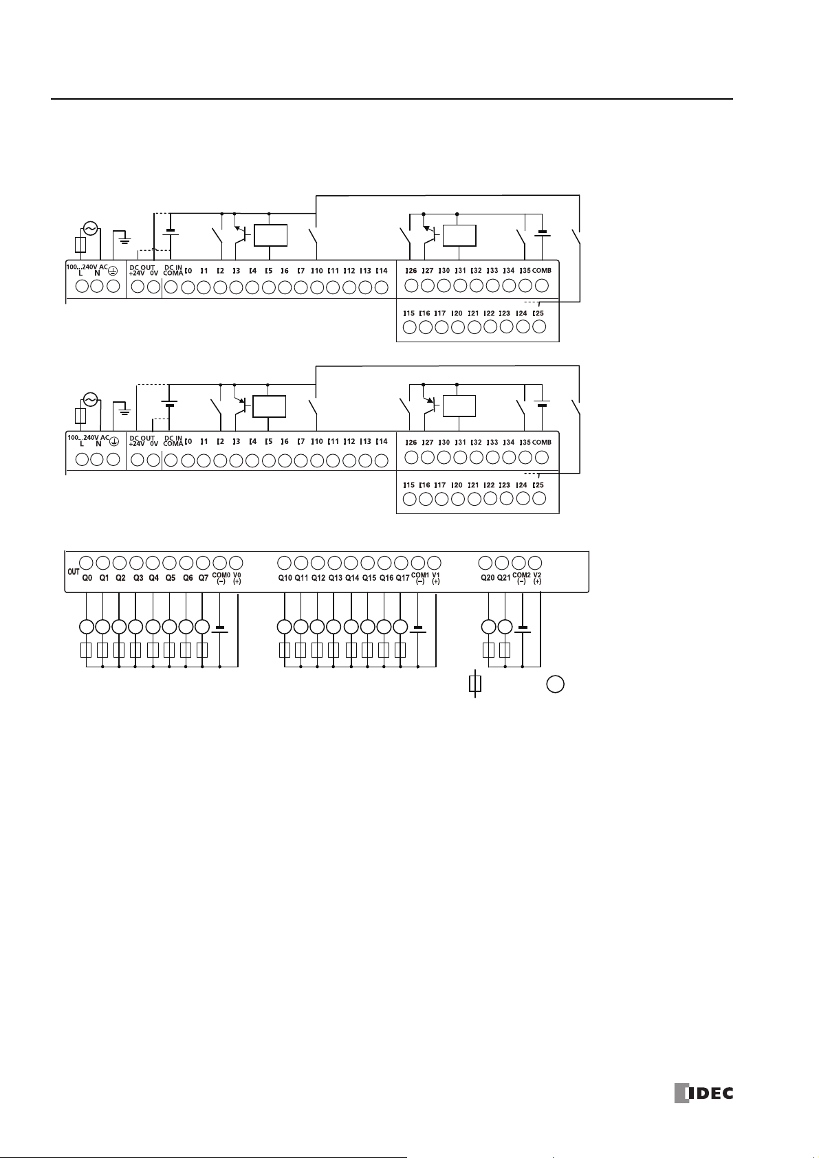
2: P
Input Side
Output Side
●
Sink Input
●
Source Input
LLLLLLLL LLLLLLLL LL
●
Sink Output
L
: Load
: Fuse
Tr.
+
-
+
-
+
-
+
-
+
-
+
-
+
-
+
-
2-wire
Sensor
External
Power
2-wire
Sensor
External
Power
2-wire
Sensor
External
Power
2-wire
Sensor
External
Power
RODUCT SPECIFICATIONS
FT1A-H48KC, FT1A-B48KC
Terminal Arrangement and I/O Wiring Diagrams
2-22 S
MART
AXIS PRO/L
ITE USER'S MANUAL
FT9Y-B1378

2: P
RODUCT SPECIFICATIONS
Communication Cartridge
Functions
By installing a communication cartridge on the SmartAXIS expansion communication port, the SmartAXIS can communicate with
communication devices supporting RS232C/RS485, such as Modbus RTU compliant devices, barcode readers, or operator
interfaces.
Specifications
Type No. Item Specifications
Termination Connector Mini DIN
Standards EIA RS232C
Maximum Baud Rate 115,200 bps
FT1A-PC1
FT1A-PC2
FT1A-PC3
Note: For details on recommended communication cables, see "Cables" on page A-8.
Communication Functions Maintenance communication, User communication, Modbus RTU master/slave
Isolation between Internal Circuit
and Communication Port
Recommended Communication Cable Special cable
Termination Connector Mini DIN
Standards EIA RS485
Maximum Baud Rate 115,200bps
Communication Functions Maintenance communication, User communication, Modbus RTU master/slave
Isolation between Internal Circuit
and Communication Port
Recommended Communication Cable Special cable
Termination Connector Screw Terminal block
Standards EIA RS485
Maximum Baud Rate 115,200 bps
Communication Functions Maintenance communication, User communication, Modbus RTU master/slave
Isolation between Internal Circuit
and Communication Port
Recommended Communication Cable
Maximum Cable Length 200m
Not isolated
Not isolated
Not isolated
Twisted-pair shielded cable with a minimum core wire of 0.3 mm
(Conductor resistance 85 /km maximum, shield resistance 20 /km maximum)
2
Installation Procedure
Remove the expansion communication port cover by inserting a flat head screwdriver into the slots at the top and bottom of the
cover. Press in the tabs at either end of the cover and lift the cover directly upward.
Expansion Communication Port Cover
Flat Head Screwdriver
Slot
S
MART
AXIS PRO/L
ITE USER'S MANUAL
FT9Y-B1378 2-23

2: P
With communication
cartridges installed.
Communication Cartridge
• T urn off the power to the SmartAXIS before removing or installing a communication cartridge.
• If a communication cartridge is installed while the SmartAXIS is powered, the SmartAXIS or the communication
cartridge may be damaged.
Caution
RODUCT SPECIFICATIONS
After removing the expansion communication port cover, carefully install a communication cartridge on the SmartAXIS expansion
communication port. Ensure that the cartridge is installed with the correct orientation.
Removal Procedure
As in the procedure to remove the expansion communication port cover, insert a flat head screwdriver into the slots, press in the
tabs at either end of the communication cartridge, and lift it directly upward. If the cartridge is removed in a crooked state, the
housing of the cartridge or the internal connector may be damaged.
2-24 S
MART
AXIS PRO/L
ITE USER'S MANUAL
FT9Y-B1378

2: P
• Compatibility of User Program with PLC System Software
When a memory cartridge contains a user program for higher functionality, do not install the memory cartridge into
PLCs with lower functionality, otherwise the user program syntax error occurs. Upgrade the system softwa re of the
PLCs so the PLCs can run the user program in the memory cartridge.
Caution
Flat Head Screwdriver
Memory Cartridge Cover
RODUCT SPECIFICATIONS
Memory Cartridge
Functions
By installing a memory cartridge on which a user program is stored to the SmartAXIS, it is possible to change the user program
executed by the SmartAXIS without using WindLDR. It is also possible to download a user program from a memory cartridge to the
SmartAXIS. The user program stored in the SmartAXIS ROM can also be uploaded to a memory cartridge.
Memory Cartridge User Program Execution Priority
• When a memory cartridge is installed on the SmartAXIS , the user program stored in the
memory cartridge is executed.
• User programs can be downloaded from memory cartridges to the SmartAXIS using the
Installed on the SmartAXIS
Not installed on the SmartAXIS The user program stored in the SmartAXIS ROM is executed.
Note: Program capacity when using a memory cartridge is the same as the program capacity of the applicable SmartAXIS model. See "Function
Specifications" on page 2-6.
Specifications
Item Specifications
Type Number FT1A-PM1
Memory Type Flash ROM
Hardware for Storing Data SmartAXIS
Quantity of Stored Programs One user program per memory cartridge
memory cartridge download function or LCD operation (SmartAXIS Pro only).
• User programs can be uploaded to memory cartridges from the SmartAXIS ROM using the
memory cartridge upload function or LCD operation (SmartAXIS Pro only).
For details, see "Memory Cartridge" on page 5-49.
User Program Compatibility
The SmartAXIS can execute only user programs created for the same PLC type. When installing a memory cartridge, make sure
that the user program stored on the memory cartridge matches the PLC type. If the user program is not for the same PLC type, a
user program syntax error occurs and the PLC cannot run the user program.
Installation Procedure
Insert a flat head screwdriver under the memory cartridge cover and pull the cover di re c t l y u pwa rd to remove it.
S
MART
AXIS PRO/L
ITE USER'S MANUAL
FT9Y-B1378 2-25
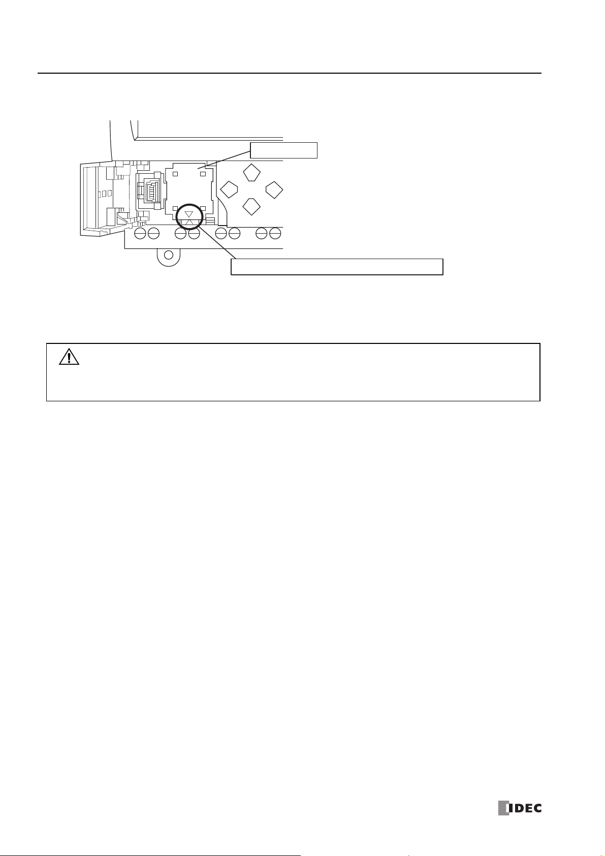
2: P
Memory Cartridge
Ensure that the cartridge is installed with the correct orientation.
• T urn off the power to the SmartAXIS before removing or installing a memory cartridge.
If a memory cartridge is installed while the SmartAXIS is powered, the SmartAXIS or the memory cartridge may be
damaged.
• Do not damage the SmartAXIS with the screwdriver.
Caution
RODUCT SPECIFICATIONS
After removing the memory cartridge cover, install a memory cartridge. Confirm that the triangular marks on the memory cartridge
and on the SmartAXIS point at each other to ensure that the memory cartridge is installed with the correct orientation.
Removal Procedure
As in the procedure to remove the memory cartridge cover, insert a flat head screwdriver under the memory cartridge cover and
pull the cover directly upward to remove it. If the cartridge is removed in a crooked state, the housing of the cartridge or the
internal connector may be damaged.
2-26 S
MART
AXIS PRO/L
ITE USER'S MANUAL
FT9Y-B1378
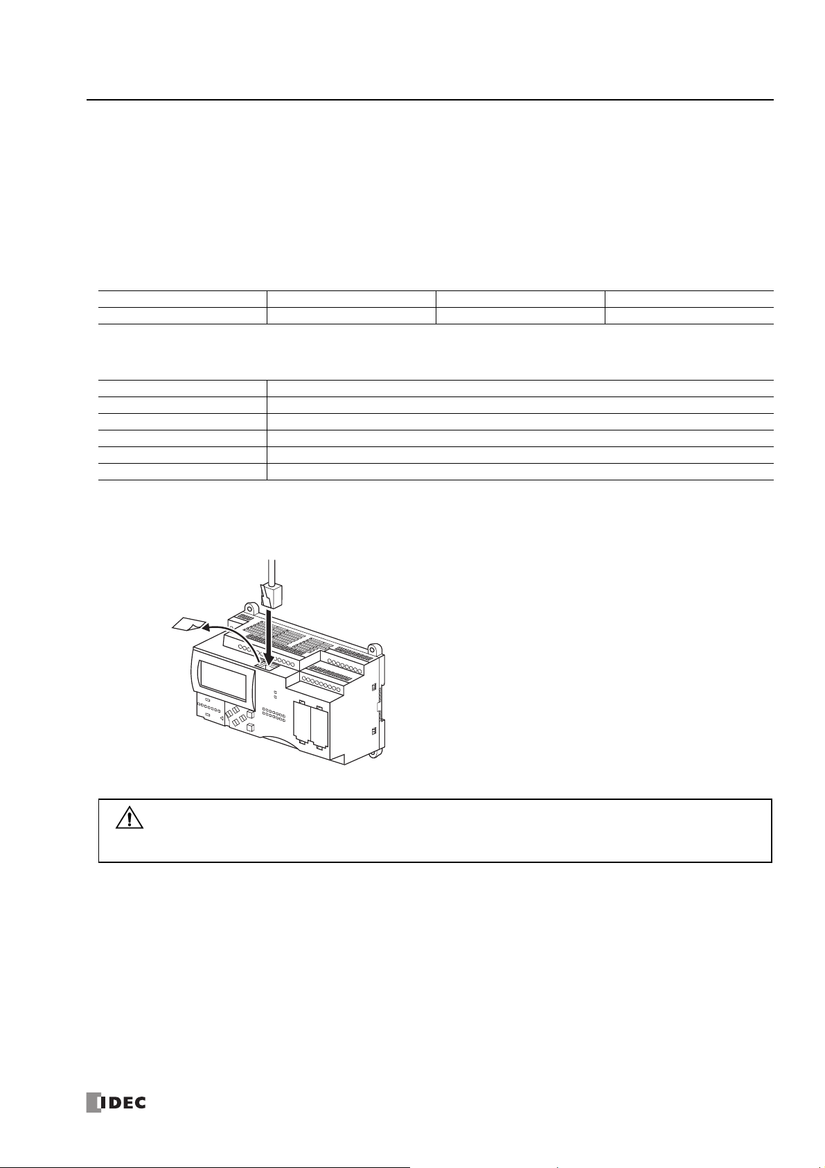
2: P
(2) Insert the connector
(1) Remove protective seal
• Turn off the power to the SmartAXIS before connecting an Ethernet cable to the Ethernet port.
• If an Ethernet cable is connected while the SmartAXI S is powered, electrica l shock to the operato r or damage to the
SmartAXIS may be caused.
Caution
RODUCT SPECIFICATIONS
Ethernet Port
Functions
SmartAXIS with Ethernet port can communicate with other network devices that support Ethernet communications, such as
maintenance communication, Modbus TCP (client and server) communication, and user-defined communication (ETXD and ERXD
commands).
Applicable Models
An Ethernet port is available on the 24-, 40-, and 48-I/O types.
12-I/O type 24-I/O type 40-I/O type 48-I/O type
No Yes Yes Yes
Specifications
Item Specifications
Transmission Speed 10BASE-T/100BASE-TX
Electrical Characteristics IEEE 802.3-compliant
Recommended Cable CAT.5 STP (Category 5 shielded twisted-pair cable)
Connector RJ45
AutoMDI/MDI-X Function Yes (when only two SmartAXIS are connected, they can be directly connected with a straig ht cable)
Installation Procedure
Remove the protective seal covering the Ethernet port and insert the connector of an Ethernet cable securely.
S
MART
AXIS PRO/L
ITE USER'S MANUAL
FT9Y-B1378 2-27

2: P
RODUCT SPECIFICATIONS
SD Memory Card
Applicable Models
SD memory cards can be used only with the 40- and 48-I/O types.
12-I/O type 24-I/O type 40-I/O type 48-I/O type
No No Yes Yes
SD Memory Card Usage
Specified device values can be saved in CSV files on an SD memory card using the DLOG and TRACE instructions/FB. This makes it
possible to save log data or analyze the data when an error occurs.
CSV files saved on an SD memory card can be read out to a computer using WindLDR.
For details on the DLOG and TRACE instructions, see Chapter 26 "Data Log Instructions" in the "SmartAXIS Ladder Programming
Manual". For details on the DLOG and TRACE FB, see Chapter 16 "The data logging FB" in the "SmartAXIS FBD Programming
Manual".
Specifications
Item Specifications
Supported SD Memory Cards SD memory cards (2GB maximum), SDHC memory cards (32GB maximum)
FAT16/FAT32
File System
Format CSV
Size 5MB maximum
File
Specifications
Maximum Number of Files
Supported
Characters
SD memory cards of 2GB or less are only supported in FAT16 format. SD memory cards of 2GB
formatted in FAT32 are not recognized.
Single-byte alphanumeric characters
The following characters cannot be used in drive names:
\ " & ( ) * + , . / : ; < > [ ] = | ^
The following characters cannot be used in file and folder names:
\ / : * ? " < >
Dependant on file system:
• FAT16
65,534 maximum per sub-directory
• FAT32
65,534 maximum per sub-directory
Recommended SD Memory Card
Recommended SD Memory Card SDHC memory cards (32GB maximum)
Notes:
• It is recommended that SDHC memory cards are formatted on the SmartAXIS before it is used.
• It is recommended that important data is regularly backed up on separate media such as CDs or DVDs.
2-28 S
MART
AXIS PRO/L
ITE USER'S MANUAL
FT9Y-B1378

2: P
If any of the actions below are performed while the SD memory card is being accessed, data on the card
may be damaged:
• The SmartAXIS is turned off.
• The SD memory card is removed.
Do not turn off the SmartAXIS while the SD memory card is being accessed (while the SD memory card
status LED is flashing). Confirm that the SD memory card status LED is not flashing before removing the
card from the SmartAXIS. For details on SD memory card status LED, see "SD Memory Card Maintenance
with WindLDR" on page 5-53.
Caution
RODUCT SPECIFICATIONS
Installation
Follow the indications on the SmartAXIS and insert an SD memory card into the SD memory card slot on the SmartAXIS until you
hear a click.
Removal
Press the SD memory card in the SD memory card slot on the SmartAXIS until you hear a click and move your finger back.
The SD memory card will come partially out of the slot. Use your fingers to remove the SD memory card completely.
Notes:
• Insert and remove the SD memory card in the direction indicated on the SmartAXIS.
• Set the write-protect switch of the SD memory card to the OFF position before inserting into the SmartAXIS.
S
MART
AXIS PRO/L
ITE USER'S MANUAL
FT9Y-B1378 2-29

2: P
90.0
100.0
2-
Ø
4.5
76.0
110.3
11.0
5.0*
76.0
90.0
60.0
56.0
Direct Mounting Hole Layout
90.0
100.0
2-
Ø4.5
76.0
110.3
5.0*
11.090.0
76.0
60.0
56.0
Direct Mounting Hole Layout
RODUCT SPECIFICATIONS
Dimensions
FT1A-H12RA
*9.3mm when the clamp is pulled out.
FT1A-B12RA
*9.3mm when the clamp is pulled out.
2-30 S
MART
AXIS PRO/L
ITE USER'S MANUAL
FT9Y-B1378

FT1A-H12RC
90.0
100.0
2- Ø
4.5
76.0
110.3
11.0
5.0*
76.0
90.0
78.0
74.0
Direct Mounting Hole Layout
90.0
100.0
2-Ø 4.5
76.0
110.3
11.05.0*
76.0
90.0
78.0
74.0
Direct Mounting Hole Layout
100.0
2- Ø4.5
90.0
119.0
110.3
11.05.0*
119.0
60.0
56.0
Direct Mounting Hole Layout
*9.3mm when the clamp is pulled out.
FT1A-B12RC
2: P
RODUCT SPECIFICATIONS
*9.3mm when the clamp is pulled out.
FT1A-H24RA
*9.3mm when the clamp is pulled out.
S
MART
AXIS PRO/L
ITE USER'S MANUAL
FT9Y-B1378 2-31

2: P
100.0
2- Ø 4.5
90.0
119.0
110.3
11.05.0*
119.0
90.0
60.0
56.0
Direct Mounting Hole Layout
100.0
2-Ø
4.5
90.0
119.0
110.3
11.05.0*
119.0
90.0
78.0
74.0
Direct Mounting Hole Layout
100.0
2-Ø 4.5
90.0
119.0
110.3
11.0
5.0*
119.0
90.0
78.0
74.0
Direct Mounting Hole Layout
RODUCT SPECIFICATIONS
FT1A-B24RA
*9.3mm when the clamp is pulled out.
FT1A-H24RC
*9.3mm when the clamp is pulled out.
FT1A-B24RC
*9.3mm when the clamp is pulled out.
2-32 S
MART
AXIS PRO/L
ITE USER'S MANUAL
FT9Y-B1378
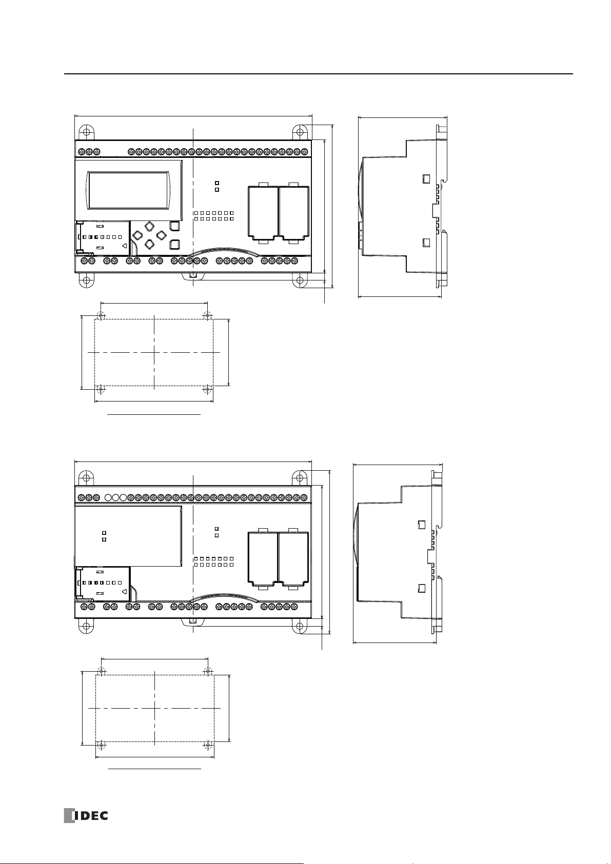
FT1A-H40RSA, FT1A-H40RKA
160.0
90.0
144.0
100.0
5.0*
160.0
90.0
110.0
60.0
56.0
Direct Mounting Hole Layout
160.0
90.0
144.0
100.0
5.0*
160.0
90.0
110.0
60.0
56.0
Direct Mounting Hole Layout
2: P
RODUCT SPECIFICATIONS
*9.3mm when the clamp is pulled out.
FT1A-B40RSA, FT1A-B40RKA
*9.3mm when the clamp is pulled out.
S
MART
AXIS PRO/L
ITE USER'S MANUAL
FT9Y-B1378 2-33

2: P
160.0
90.0
144.0
100.0
5.0*
160.0
90.0
110.0
78.0
74.0
Direct Mounting Hole Layout
160.0
90.0
144.0
100.0
5.0*
160.0
90.0
110.0
78.0
74.0
Direct Mounting Hole Layout
RODUCT SPECIFICATIONS
FT1A-H40RC
*9.3mm when the clamp is pulled out.
FT1A-B40RC
*9.3mm when the clamp is pulled out.
2-34 S
MART
AXIS PRO/L
ITE USER'S MANUAL
FT9Y-B1378

FT1A-H48SA, FT1A-H48KA
160.0
90.0
144.0
100.0
5.0*
160.0
90.0
110.0
78.0
74.0
Direct Mounting Hole Layout
160.0
90.0
144.0
100.0
5.0*
160.0
90.0
110.0
78.0
74.0
Direct Mounting Hole Layout
2: P
RODUCT SPECIFICATIONS
*9.3mm when the clamp is pulled out.
FT1A-B48SA, FT1A-B48KA
*9.3mm when the clamp is pulled out.
S
MART
AXIS PRO/L
ITE USER'S MANUAL
FT9Y-B1378 2-35

2: P
160.0
90.0
144.0
100.0
78.0
74.0
5.0*
160.0
90.0
110.0
Direct Mounting Hole Layout
160.0
90.0
144.0
100.0
78.0
74.0
5.0*
160.0
90.0
110.0
Direct Mounting Hole Layout
RODUCT SPECIFICATIONS
FT1A-H48SC, FT1A-H48KC
*9.3mm when the clamp is pulled out.
FT1A-B48SC, FT1A-B48KC
*9.3mm when the clamp is pulled out.
2-36 S
MART
AXIS PRO/L
ITE USER'S MANUAL
FT9Y-B1378

3: I
• Turn off the power to the SmartAXIS before starting installation, removal, wiring, maintenance, and inspection of th e
SmartAXIS. Failure to turn power off may cause electrical shocks or fire hazard.
• Emergency stop and interlocking circuits must be configured outside the SmartAXIS. If such a circuit is configured
inside the SmartAXIS, failure of the Sm artAXIS may cause disorder of the control system, damage, or accidents.
• Special expertise is required to install, wire, program, and operate the SmartAXIS. People without such expertise must
not use the SmartAXIS.
Warning
• Prevent metal fragments and pieces of wire fr om dropping inside the SmartAXIS housing. Put a cover on the
SmartAXIS modules during installation and wiring. Ingress of such fragments and chips may cause fire hazard,
damage, or malfunction.
• Do not touch the connector pins with your hand. Electrostatic discharge may damage the internal elements.
• When handling the SmartAXIS, take measures to discharge static electricity.
• Keep the SmartAXIS wiring away from motor lines.
Caution
SmartAXIS LiteSmartAXIS Pro
NSTALLATION AND
W
IRING
Introduction
This chapter describes the methods and precautions for installing and wiring SmartAXIS modules.
Before starting installation and wiring, be sure to read “Safety Precautions” in the beginning of this manual and understand
precautions described under Warning and Caution.
Installation Location
The SmartAXIS is designed to be installed in control panels and similar locations.
Install the SmartAXIS within product specifications.
Avoid use in the environments below, as doing so may cause electric shock, fire, or malfunction:
Places where there is a lot of dust, salt, iron powder, or soot.
Places exposed to direct sunlight.
Places where the SmartAXIS may be exposed to vibration or shock, either directly or indirectly.
Atmospheres of corrosive or flammable gases.
Places where condensation may form.
Places where the SmartAXIS may be directly exposed to water.
Around high-voltage lines, high-voltage equipment, motor lines, or motor equipment.
Places near where a large switching surge may occur.
Places subject to a strong magnetic or electrical field.
Always mount the SmartAXIS vertically as shown below. To provide ample ventilation, ensure that there is sufficient space
between the SmartAXIS and other devices, heat sources, and panel surfaces.
S
MART
AXIS PRO/L
ITE USER'S MANUAL
FT9Y-B1378 3-1
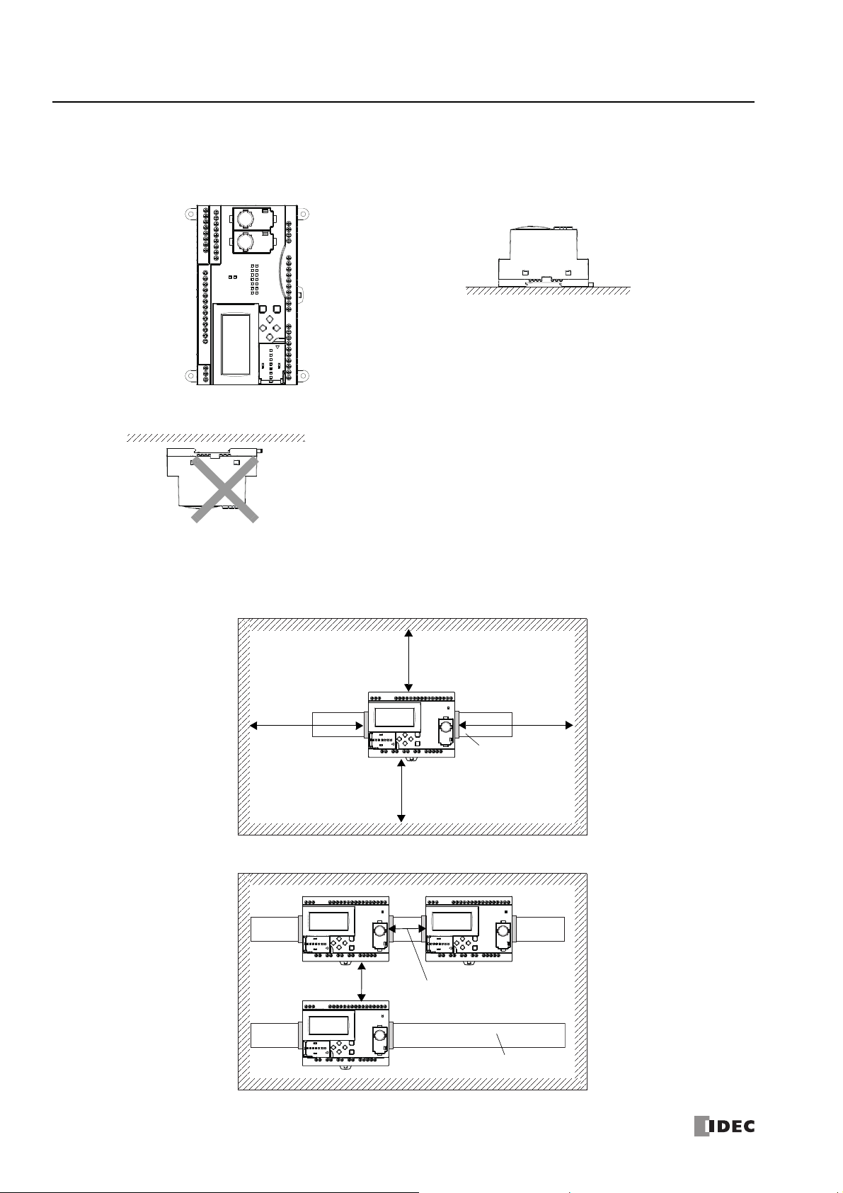
3: I
Face Up Orientation (Use if 35°C or less)Side Orientation (Use if 40°C or less)
Face Down
20mm minimum
20mm minimum
40mm minimum
40mm minimum
DIN Rail
20mm minimum
40mm minimum
DIN Rail
NSTALLATION AND WIRING
The SmartAXIS can be mounted face up when the ambient temperature is 35°C or lower, and can be mounted on its side when the
ambient operating temperature is 40°C or lower. Do not mount the SmartAXIS on its side when the ambient temperature will
exceed 40°C.
Do not install the SmartAXIS face down.
Mounting Space
To allow for heat dissipation and facilitate replacement, ensure that there are at least 20 to 40mm between the SmartAXIS and
surrounding equipment and ducts.
Mounting Two or More Units
3-2 S
MART
AXIS PRO/L
ITE USER'S MANUAL
FT9Y-B1378
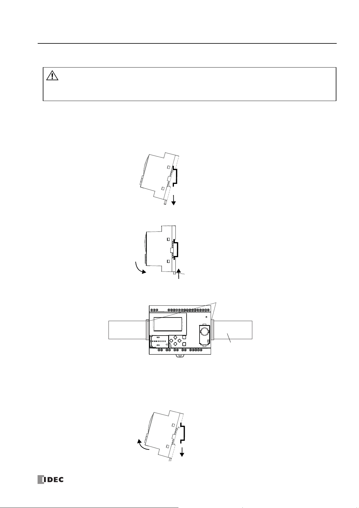
Mounting on DIN Rail
• Install the SmartAXIS modules according to instructions described in this user’s manual. Improper installation will
result in falling, failure, or malfunction of the SmartAXIS.
• Do not install the SmartAXIS when it is powered up. Doing so may result in electric shock and may damage the
product.
Caution
(2) Clamp SmartAXIS over DIN rail.
(1) Lower DIN rail clamp.
DIN Rail
DIN Rail
(2) Raise DIN rail clamp.
(1) Align with DIN rail.
DIN Rail Bracket (BNL6)
DIN Rail
DIN Rail
(2) Pull outward and upward.
(1) Lower DIN rail clamp.
This section describes how to mount the SmartAXIS.
The SmartAXIS can be mounted directly on a DIN rail or in a control pane l.
1. Firmly fasten the DIN rail to a panel using screws.
2. Using a flat head screwdriver, lower the DIN rail clamp and hang the SmartAXIS on the DIN rail.
3: I
NSTALLATION AND WIRING
3. Align the SmartAXIS with the DIN rail and raise the DIN rail clamp.
4. Secure both ends of the SmartAXIS using the DIN rail brackets.
Removing from DIN Rail
1. Using a flat head screwdriver, lower the DIN rail clamp on the SmartAXIS.
2. Pull the SmartAXIS outward and upward at the same time.
Note: The SmartAXIS supports 35mm wide DIN rails. Supported rails: IDEC BAA1000 (Length: 1000mm)
S
MART
AXIS PRO/L
ITE USER'S MANUAL
FT9Y-B1378 3-3
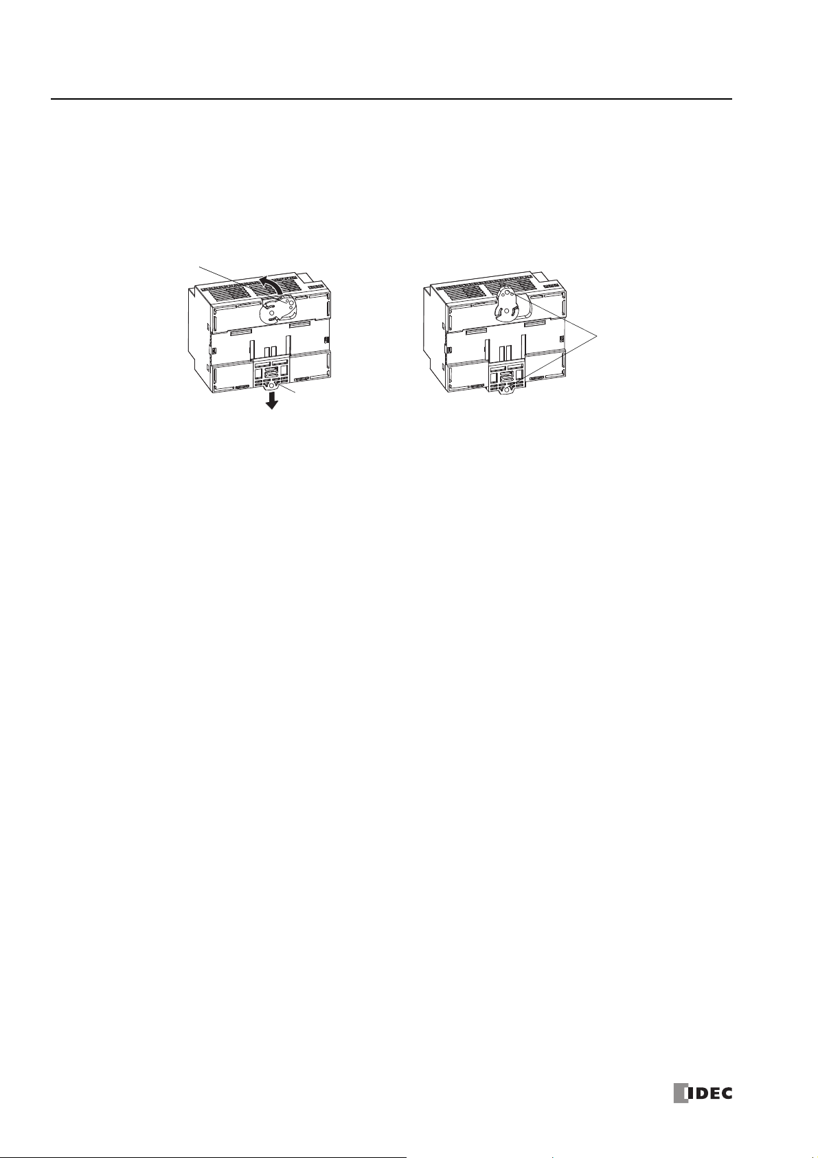
3: I
Screw Hole
DIN Rail Clamp
Direct-mounting Plate
NSTALLATION AND WIRING
Direct Mounting on Panel Surface
This section describes how to mount the SmartAXIS directly onto a mounting plate for installation in a control panel. The 12- and
24-I/O types are mounted differently from the 40- and 48-I/O types. To mount the SmartAXIS directly, it may be necessary to
make holes in the mounting plate depending on the SmartAXIS model.
Preparations
When directly mounting the 12- and 24-I/O types, pull out the direct-mounting plate and the DIN rail clamp on the back of the
SmartAXIS, and attach the SmartAXIS to the mounting plate using the screw holes. Attach the 40- and 48-I/O types to the
mounting plate using the screw holes on the back of the SmartAXIS.
3-4 S
MART
AXIS PRO/L
ITE USER'S MANUAL
FT9Y-B1378
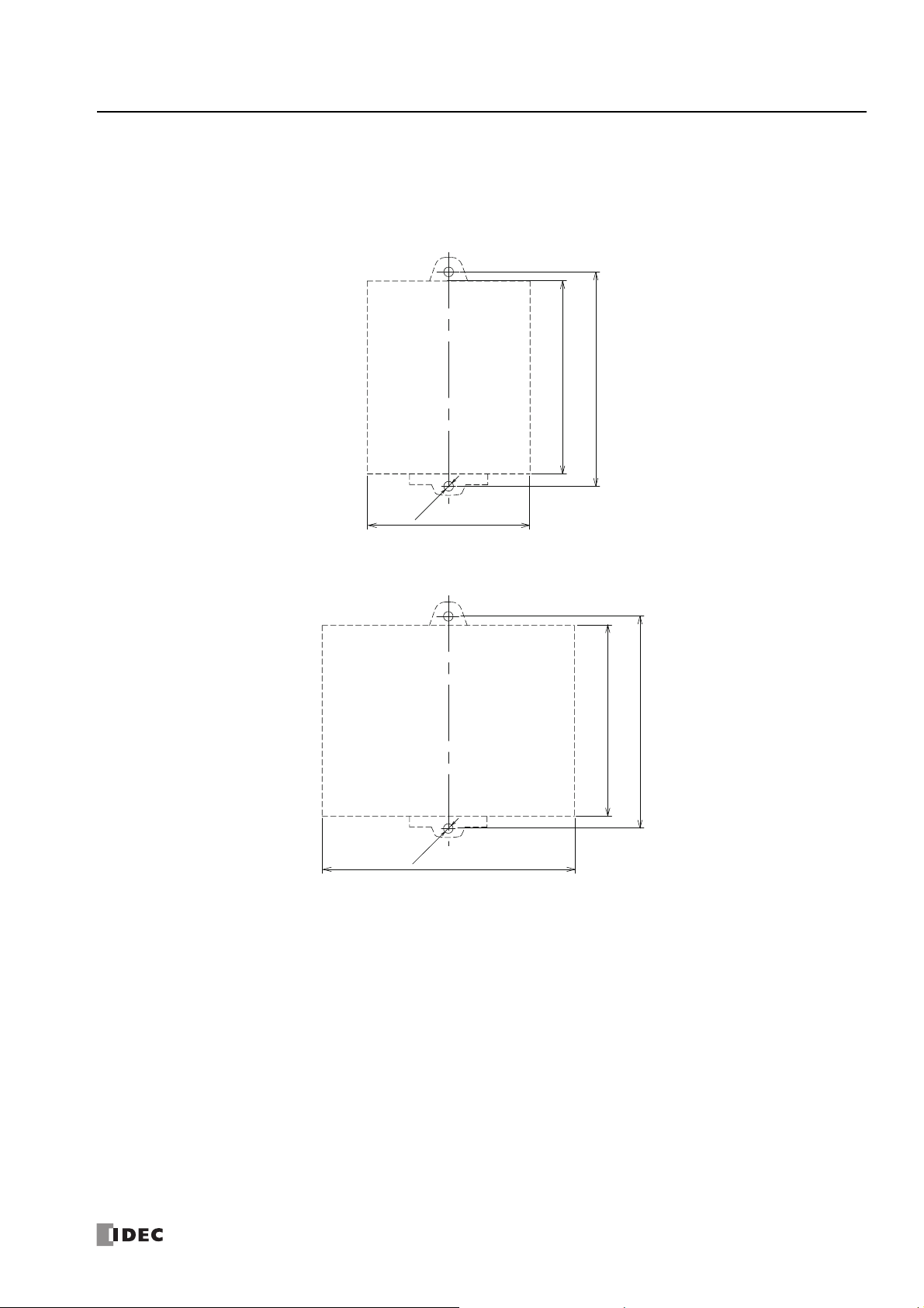
3: I
All dimensions in mm.
100
2-Ø4.5
(76)
(90)
All dimensions in mm.
100
(90)
(119)
2-Ø4.5
NSTALLATION AND WIRING
Mounting Hole Layout for Direct Mounting on Panel Surface
Attach the SmartAXIS to the mounting plate using M4 tapping screws, as shown below, or make 5 to 6mm mounting holes and
secure the SmartAXIS using M4 pan head screws.
Always give sufficient consideration to operability, ease-of-maintenance, and environmental resistance when deciding on the
mounting position.
• 12-I/O type (FT1A-H12RA, FT1A-B12RA, FT1A-H12RC, FT1A-B12RC)
• 24-I/O type (FT1A-H24RA, FT1A-B24RA, FT1A-H24RC, FT1A-B24RC)
S
MART
AXIS PRO/L
ITE USER'S MANUAL
FT9Y-B1378 3-5
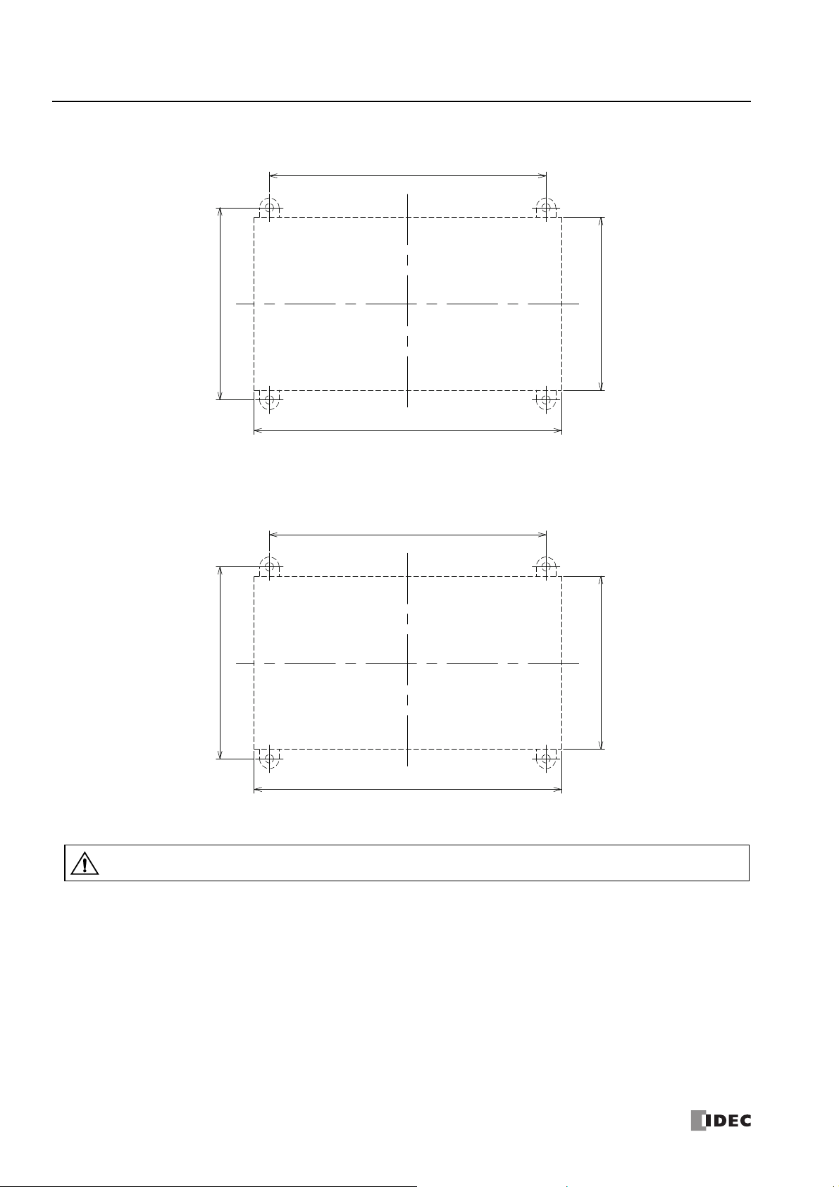
3: I
(160)
(90)
144
100
All dimensions in mm.
(160)
(90)
144
100
All dimensions in mm.
• When directly mounting the SmartAXIS, tighten mounting screws with torque of 1N·m (10kgf·cm).
Caution
NSTALLATION AND WIRING
• 40-I/O type (FT1A-H40RKA, FT1A-H40RSA, FT1A-B40RKA, FT1A-B40RSA, FT1A-H40RC, FT1A-B40RC)
• 48-I/O type
(FT1A-H48KA, FT1A-H48SA, FT1A-B48KA, FT1A-B48SA, FT1A-H48KC, FT1A-H48SC, FT1A-B48KC, FT1A-B48SC)
3-6 S
MART
AXIS PRO/L
ITE USER'S MANUAL
FT9Y-B1378
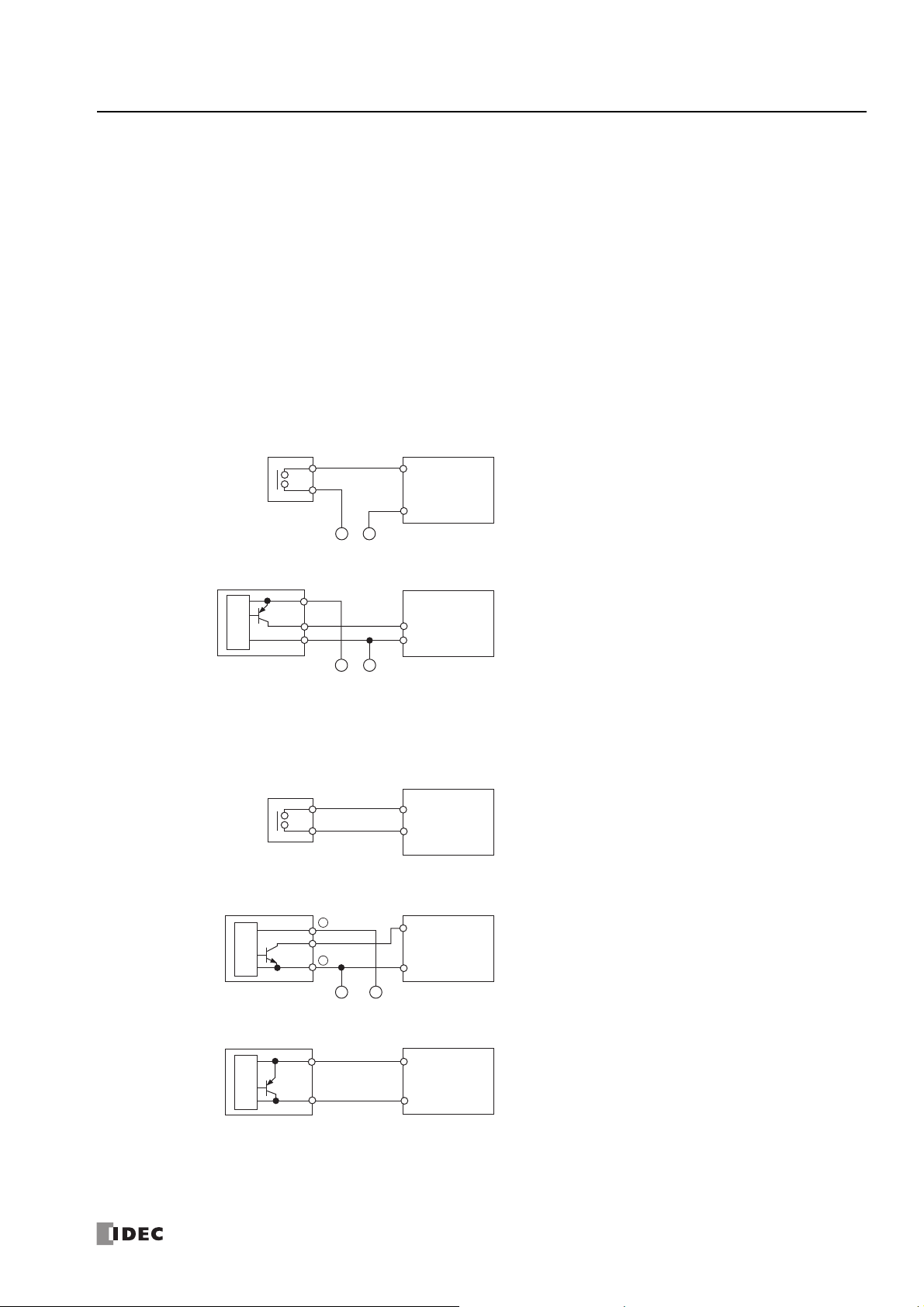
3: I
NSTALLATION AND WIRING
Input/Output Wiring
This section describes SmartAXIS input/output device wiring.
Precautions for I/O Device Wiring
Input Terminal Wiring
When wiring input devices, separate wiring from power, output, and motor lines.
When using duct for wiring, ground piping using a D-type (type 3) ground.
When wiring DC power type models, keep wiring away from AC power lines.
When using shielded cable for wiring, ground the shield on the SmartAXIS side using a D-type (type 3) ground.
Wire input devices you want to connect to the SmartAXIS according to type as shown below.
DC Power Type
Digital Input – Sink Input
• Contact Output
• PNP Output
Digital Input –
• Contact Output
Internal
Circuit
Sensor Output
Source Input
Output
+
-
External Power
+
-
External Power
SmartAXIS
Input Terminal (I*)
0V Power Supply
-
Terminal (
SmartAXIS
Input Terminal (I*)
0V Power Supply
Terminal (
SmartAXIS
Input Terminal (I*)
24V Power Supply
Terminal (
)
-
)
-
)
• NPN Output
• 2-wire Sensor
Internal
Circuit
Internal
Circuit
+
Output
-
-
External Power
S
MART
SmartAXIS
Input Terminal (I*)
0V Power Supply
Terminal (
+
SmartAXIS
Input Terminal (I*)
24V Power Supply
Terminal (
AXIS PRO/L
-
)
-
)
ITE USER'S MANUAL
FT9Y-B1378 3-7

3: I
Input Terminal (I*)
0V Power Supply
Terminal (
-
)
Input Terminal (I*)
0V Power Supply
Terminal (
-
)
0V Power Supply
Terminal (
-
)
• Contact Output
External Power
SmartAXIS
SmartAXIS
• PNP Output
External Power
Sensor Output
SmartAXIS
• Analog Output
Input Terminal (I*)
Analog Output
Terminal
COM
-
+
-
+
Output
Internal
Circuit
• Contact Output
Input Terminal (I*)
SmartAXIS
COM
• Contact Output
SmartAXIS
SmartAXIS
COM
COM
• NPN Output
Sensor
Vcc
0
V
Sensor Power Supply
/ External Power
Sensor Power Supply
/ External Power
Input Terminal (I*)
Input Terminal (I*)
-
-
+
+
-
+
Output
Internal
Circuit
NSTALLATION AND WIRING
Shared Analog Input
AC Power Type
3-8 S
Contact Input
Sink/Source Input
MART
AXIS PRO/L
ITE USER'S MANUAL
FT9Y-B1378
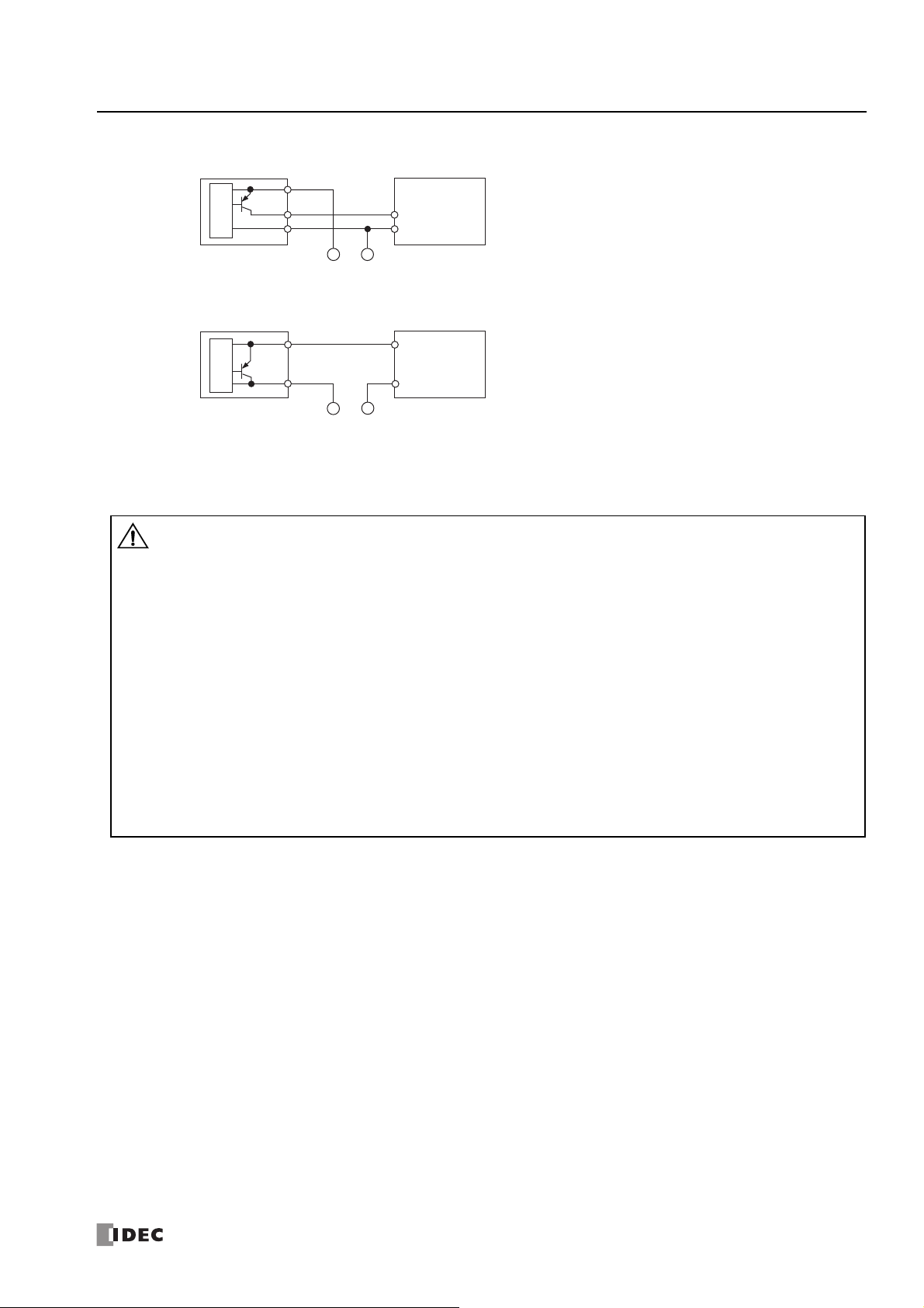
3: I
• If output relays or transistors in the SmartAXIS or output modules should fail, outputs may remain on or off. For
output signals which may cause heavy accidents, provide a monitor circuit outside the SmartAXIS.
• Connect a fuse to the output module, selecting a fuse appropriate for the load.
• Use proper wires for output wiring.
UL1015 AWG22 or UL1007 AWG18
• When equipment containing the SmartAXIS is intended for use in European countries, insert an IEC 60127-approved
fuse to each output of every module for pro tectio n against o verl oad or short-circuit. This is required wh en equipment
containing the SmartAXIS is destined for Europe.
• When driving an inductive load that emits noise like a magnet or a valve, to reduce noise and protect circuits, use a
diode for the output on DC power type models and a surge absorber for the output on AC power type models.
• Turn off the power to the SmartAXIS when wiring input/output terminals.
• Emergency stop and interlocking circuits must be configured outside the SmartAXIS.
• Use the input/output terminals within the SmartAXIS ratings and specifications.
• Tighten mounting screws with torque of 0.5N·m (5 gf·cm).
Caution
NSTALLATION AND WIRING
• PNP Output
Internal
Circuit
Sensor Output
• 2-wire Sensor
Internal
Circuit
Output Terminal Wiring
Output
+
Sensor Power Supply
/ External Power
-
Sensor Power Supply
/ External Power
SmartAXIS
Input Terminal (I*)
COM
-
SmartAXIS
Input Terminal (I*)
COM
+
S
MART
AXIS PRO/L
ITE USER'S MANUAL
FT9Y-B1378 3-9

3: I
Inductive Load
COM
C
R
Output Q
This protection circuit can be used when the load impedance is smaller
than the RC impedance in an AC load power circuit.
R: Resistor of approximately the same resistance value as the load
C: 0.1 to 1 µF
Inductive Load
COM
R
Output Q
C
+or–
Surge Killer
This protection circuit can be used for both AC and DC load power
circuits.
R: Resistor of approximately the same resistance value as the load
C: 0.1 to 1 µF
Inductive Load
COM
Output Q
+–
Diode
This protection circuit can be used for DC load power circuits.
Use a diode with the following ratings.
Reverse withstand voltage: Power voltage of the load circuit × 10
Forward current:More than the load current
Inductive Load
COM
Output Q
+or–
Varistor
This protection circuit can be used for both AC and DC load power
circuits.
NSTALLATION AND WIRING
Output Protection Circuit
When a motor, solenoid, or similar inductive load is connected, the life of the contact is shortened due to the inrush current and
counter-electromotive force acting on the load. Set up a protection circuit to prevent this from happening. Choose a protection
circuit from A through D shown below, according to the power supply, and connect the protection circuit to the outside of the
SmartAXIS.
For protection of the transistor output of the SmartAXIS modules, connect protection circuit C shown below to the transistor output
circuit.
Protection Circuit A
Protection Circuit B
Protection Circuit C
Protection Circuit D
MART
AXIS PRO/L
ITE USER'S MANUAL
3-10 S
FT9Y-B1378

3: I
• Use a power supply of the rated value. Use of the wrong power supply may cause fire or malfunction.
• Ensure that the power voltage to the SmartAXI S does not ex ce ed the allow able powe r voltage range described in the
power supply specifications. The SmartAXIS may run an d stop re peatedly wit hin this vo ltage r ange , particul arly if the
power voltage turns on or off very slowly.
• Use an IEC 60127-approved fuse on the power line outside the SmartAXIS. This is required when equipment
containing the SmartAXIS is destined for Europe.
Caution
85 to 264V AC
Fuse
20.4 to 28.8V DC
Fuse
NSTALLATION AND WIRING
Power Supply
This section describes how to connect a power supply to the SmartAXIS. The SmartAXIS is available in both AC and DC power
types.
AC Power Type
Connect the power supply to the AC power types, as shown below.
Example: FT1A-*12**C
When Power Is Turned Off
The AC power types detect a power failure when the power voltage drops below 85V AC.
A momentary power interruption of 10ms or less is not recognized as a power failure when the power voltage is at the rated
voltage.
Inrush Current at Powerup
When the SmartAXIS is powered up, there is an inrush current of a maximum of 35A flows. Use a power supply with sufficient
capacity.
DC Power Type
Connect the power supply to the DC power types as shown below.
Example: FT1A-*12**A
When Power Is Turned Off
The DC power types detect a power failure when the power voltage drops below 20.4V DC.
A momentary power interruption of 10ms or less is not recognized as a power failure when the power voltage is at the rated
voltage.
Inrush Current at Powerup
When the SmartAXIS is powered up, there is an inrush current of a maximum of 30A flows. Use a power supply with sufficient
capacity.
S
MART
AXIS PRO/L
ITE USER'S MANUAL
FT9Y-B1378 3-11

3: I
• Use the SmartAXIS within the specifications of ratings and environmental conditions. Failure to do so may cause the
SmartAXIS to break down or reduce product life.
• Be sure to connect the grounding wire to a proper ground, otherwise electrical shocks may be caused.
• Do not touch live terminals, otherwise electrical shocks may be caused.
• When connecting the power supply, tighten the terminal screws with torque of 0.5N·m (5kgf·cm).
Caution
SmartAXIS
Inverter or
similar external
device
D-type ground
(class 3)
SmartAXIS
D-type ground
(class 3)
SmartAXIS
A
B
Length A = B
Inverter or
similar external
device
Inverter or
similar external
device
NSTALLATION AND WIRING
Power Supply Wiring
When connecting the power supply, be sure to take care of the following:
• Use a stranded wire of UL1015 AWG22 or UL1007 AWG18 for power supply wiring. Make the power supply wiring as sho rt as possible.
• Run the power supply wiring as far away as possible from motor lines.
• is the protective ground terminal. To prevent electric shocks, ground the terminal with D-ty pe gr oun d (type 3: ground resistance of 100
maximum).
• is the functional ground terminal. To prevent malfunction or breakdown of the SmartAXIS due to noise, ground th e terminal with D-type
ground (class 3: ground resistance of 100 maximum).
• When connecting a stranded wire or multiple wires to a terminal block, use a ferrule.
Grounding
When grounding the power supply, be sure to take care of the following:
• Do not use the common ground for the SmartAXIS and motor equipment. The common ground can be used only when the length of
grounding wires for those devices are the same.
• Use a ground wire of UL1007 AWG16.
• Use a thick wire for grounding the SmartAXIS and make the grounding wire as short as possible to make sure that noises from external
devices can be conducted to the ground effectively.
• As shown below, external devices generating noise must be separated from the SmartAXIS and grounded with the D-type ground (class 3).
• Make the length of the grounding wire for the SmartAXIS as short as possible.
3-12 S
MART
AXIS PRO/L
ITE USER'S MANUAL
FT9Y-B1378

3: I
• Do not touch live terminals, otherwise electrical shocks may be caused.
• When the power is on, terminals to which external devi ces are connected may be heated. Do not touch terminals
immediately after the power is turned off.
• Do not touch terminals immediately after the power is turned off, otherwise electrical shocks may be caused.
• When connecting a stranded wire or multiple solid wires to a screw terminal block, use a ferrule. Otherwise the wire
may slip off the screw terminal block.
• When using ferrules, insert a wire to the bottom of the ferrule and crimp the ferrule.
Caution
0 to 0.5 mm
Damage
Whisker
Correct
Stripped wire is too short
Core wire is visible
2-wire connection
10 to 11 mm
Length of stripped wire
1-wire connection
Cable (AWG 22 to 18)
Cable (AWG 24 to 18)
Single Wire: AWG 16 to 12 (UL)
Stranded Wire: AWG 12 to 14 (JIS)
NSTALLATION AND WIRING
Terminal Connection
This section describes types of terminals and how to use them.
When connecting stranded wire or multiple solid wires to a terminal block, use appropriate ferrule for the terminal block.
Terminals for Terminal Blocks
Crimp ferrules using an appropriate tool according to the size of ferrules. Cut the end of the wire to the same length or about 0.5
mm longer than the ferrule.
Ensure that the core wire does not protrude at the end of the shield and there are no whiskers.
Ferrules
The ferrules and crimping tools below can be used.
Type numbers of the ferrules and crimping tool are the type numbers of Phoenix Contact.
Ferrule Order No.
Quantity of Cables Cable Size Phoenix Type Order No. Pcs./Pkt.
For 1-wire connection
For 2-wire connection
Crimping Tool Order No.
Crimping Tool CRIMPFOX ZA 3 12 01 88 2 1
Tool Name Phoenix Type Order No. Pcs./Pkt.
UL1007 AWG16 AI 1,5-8 BK 32 00 04 3 100
UL1007 AWG18 AI 1-8 RD 32 00 03 0 100
UL1015 AWG22 AI 0,5-8 WH 32 00 01 4 100
UL2464 AWG24 AI 0,25-8 YE 32 03 03 7 100
UL1007 AWG18 AI-TWIN 2 x 0,75-8 GY 32 00 80 7 100
UL1015 AWG22 AI-TWIN 2 x 0,5-8 WH 32 00 93 3 100
S
MART
AXIS PRO/L
ITE USER'S MANUAL
FT9Y-B1378 3-13

3: I
NSTALLATION AND WIRING
Securing the Panel Attachment USB Extension Cable
Using the panel attachment USB extension cable*1 makes it possible to perform maintenance on a SmartAXIS installed in a control
panel from the surface of the panel. When using the panel attachment USB extension cable, we recommend securing it to the USB
port cover with a cable tie
This section describes the procedure to secure the USB extension cable to the USB cover.
1. Open the SmartAXIS USB port cover and plug the panel attachment USB extension cable into the USB port.
2. Wrap the cable tie around the USB port cover and the panel attachment USB extension cable.
*2
so that it does not come loose from the SmartAXIS.
3. The cable tie can also be inserted through the holes on the USB port cover.
4. Tighten the loop until it is the suitable size and trim the excess cable tie using wire cutters.
Note 1: We recommend the panel attachment USB extension cable (part no.: HG9Z-XCE21).
Note 2: HellermanTyton cable tie T18R-1000 is recommended.
3-14 S
MART
AXIS PRO/L
ITE USER'S MANUAL
FT9Y-B1378

4: O
Introduction
This chapter describes basic procedures for operating WindLDR, programming and maintenance software for the SmartAXIS Pro/
Lite series.
Note: SmartAXIS Touch series use WindO/I-NV3 software for programming. See the “Sma rtAXIS Touch User’s Manual” for instructions for
programming and basic operation of WindO/I-NV3 with the Touch series.
Start WindLDR
From the Start menu of Windows, select Programs > Automation Organizer V2 > WindLDR > WindLDR.
WindLDR starts and a blank ladder editing screen appears with menus and tool bars shown on top of the screen.
PERATION
B
ASICS
S
MART
AXIS PRO/L
ITE USER'S MANUAL
FT9Y-B1378 4-1

4: O
Press this button, then the same PL C will be sel ected
as default when WindLDR is started next time.
PLC Selection Option
SmartAXIS
Type No.
FT1A-12
FT1A-24
FT1A-40
FT1A-48
FT1A-H12RA
FT1A-B12RA
FT1A-H12RC
FT1A-B12RC
FT1A-H24RA
FT1A-B24RA
FT1A-H24RC
FT1A-B24RC
FT1A-H40RKA
FT1A-H40RSA
FT1A-B40RKA
FT1A-B40RSA
FT1A-H40RC
FT1A-B40RC
FT1A-H48KA
FT1A-H48SA
FT1A-B48KA
FT1A-B48SA
FT1A-H48KC
FT1A-H48SC
FT1A-B48KC
FT1A-B48SC
PERATION BASICS
PLC Selection
Before programming a user program on WindLDR, select a PLC type.
1. Select Configuration from the WindLDR menu bar, then select PLC Type.
The PLC Selection dialog box appears.
2. Select a PLC type in the selection box and the programming language to use.
3. Click OK.
PLC selection is now complete. For the procedure to create the ladder program, see "Create Ladder Program" on page 4-3. For
the procedure to create the ladder program, see "Create FBD Program" on page 4-7.
4-2 S
MART
AXIS PRO/L
ITE USER'S MANUAL
FT9Y-B1378

4: O
PERATION BASICS
Create Program
Create Ladder Program
This section describes the procedure for creating a simple ladder program in WindLDR.
Note: See SmartAXIS Ladder Programming Manual for details on basic and advanced instructions.
Sample User Program
Create a simple program using WindLDR. The sample program performs the following operation:
When only input I0 is turned on, output Q0 is turned on.
When only input I1 is turned on, output Q1 is turned on.
When both inputs I0 and I1 are turned on, output Q2 flashes in 1-sec increments.
Rung No. Input I0 Input I1 Output Operation
1 ON OFF Output Q0 is turned ON.
2 OFF ON Output Q1 is turned ON.
3 ON ON Output Q2 flashes in 1-sec increments.
Note: One collection of a group of instructions that contr ol output or advanced instructions is called a rung. WindLDR manages programs in rung
units. Function descriptions can be configured as rung comments for individual rungs.
Start WindLDR
From the Start menu of Windows, select Programs > Automation Organizer V2 > WindLDR > WindLDR.
WindLDR starts and a blank ladder editing screen appears with menus and tool bars shown on top of the screen.
S
MART
AXIS PRO/L
ITE USER'S MANUAL
FT9Y-B1378 4-3

4: O
PERATION BASICS
Edit User Program Rung by Rung
Start the user program with the LOD instruction by inserting a NO contact of input I0.
1. From the WindLDR menu bar, select Home > Basic > A (Normally Open).
2. Move the mouse pointer to the first column of the first line where you want to insert a NO contact, and click the left mouse
button.
Note: Another method to insert a NO (or NC) contact is to move the mouse pointer where you want to insert the contact, and type A (or B).
The Normally Open dialog box appears.
4-4 S
MART
AXIS PRO/L
ITE USER'S MANUAL
FT9Y-B1378

4: O
PERATION BASICS
3. Enter I0 in the Tag Name field, and click OK.
A NO contact of input I0 is programmed in the first co lumn of the first ladder line.
Next, program the ANDN instruction by inserting a NC contact of input I1.
4. From the WindLDR menu bar, select Home > Basic > B (Normally Closed).
5. Move the mouse pointer to the second column of the first ladder line where you want to insert a NC contact, and click the left
mouse button.
The Normally Closed dialog box appears.
6. Enter I1 in the Tag Name field, and click OK.
An NC contact of input I1 is programmed in the second column of the first ladder line.
At the end of the first ladder line, program the OUT instruction by inserting a NO coil of output Q0.
7. From the WindLDR menu bar, select Home > Basic > OUT (Output).
8. Move the mouse pointer to the third column of the first ladder line where you want to insert an output coil, and click the left
mouse button.
Note: Another method to insert an instruction (either basic or advanced) is to type the instruction symbol, OUT, where you want to insert the
instruction.
The Output dialog box appears.
9. Enter Q0 in the Tag Name field, and click OK.
A NO output coil of output Q0 is programmed in the right-most column of the first ladder line. This completes programming for
rung 1.
Continue programming for rungs 2 and 3 by repeating similar procedures.
A new rung is inserted by pressing the Enter key while the cursor is on the preceding rung. A new rung can also be inserted
by selecting Home > Append > Append a Rung.
S
MART
AXIS PRO/L
ITE USER'S MANUAL
FT9Y-B1378 4-5

4: O
To insert a new ladder line without
creating a new rung, press the down arro w
key when the cursor is on the last line or
press the right arrow key when the cursor
is at the right-most column of the last line.
PERATION BASICS
When completed, the ladder program looks like below.
4-6 S
MART
AXIS PRO/L
ITE USER'S MANUAL
FT9Y-B1378

4: O
PERATION BASICS
Create FBD Program
This section describes the procedure for creating a sample FBD program in WindLDR.
Note: For details on each FB, see the "SmartAXIS FBD Pr ogramming Manual".
Create a program that operates in the following manner.
• When both input I0 and input I1 are on, output Q0 turns on.
• When either input I1 or input I2 is on, output Q1 continues to turn on and off in a one second cycle.
Circuit block I0 I1 I2 Action
Q0 ON ON Turn output Q0 on
Q1
Note: The output FB and all the FBs conn ected o n the le ft side of th e inpu t conn ector o f the out put FB ar e called t he ci rcuit blo ck. The output state
of the output FB is the execution result of a single circuit block.
OFF ON
ON OFF
T urn on and off the output Q1 continuously in a one
second cycle
Insert input I0
1. From the WindLDR menu bar, click Home > Function Block > Terminal > I (Digital Input).
2. Move the mouse pointer to the FBD editor and click the left mouse button.
Input I0 is inserted at the position of the mouse pointer.
S
MART
AXIS PRO/L
ITE USER'S MANUAL
FT9Y-B1378 4-7
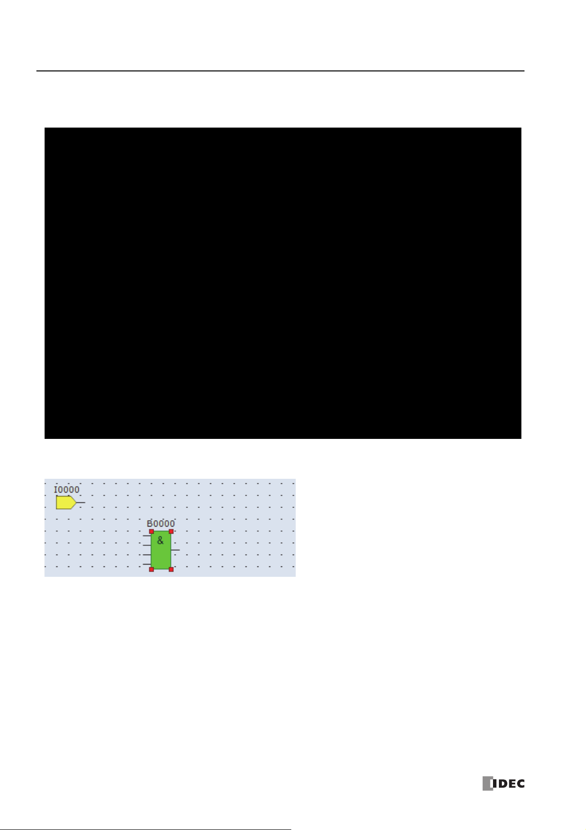
4: O
PERATION BASICS
Insert the AND (logical AND) FB
1. From the WindLDR menu bar, click Home > Function Block > Basic > AND (Logical AND).
2. Move the mouse pointer to the FBD editor and click the left mouse button.
AND B0 is inserted at the position of the mouse pointer.
4-8 S
MART
AXIS PRO/L
ITE USER'S MANUAL
FT9Y-B1378
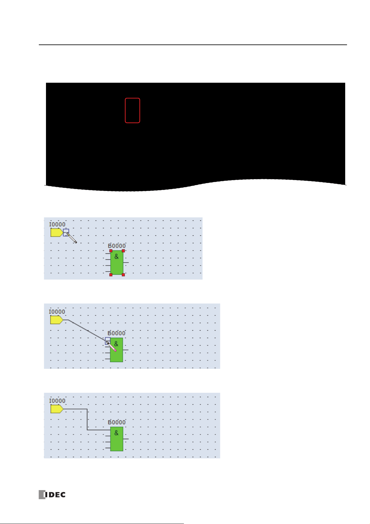
Connect input I0 and AND B0 with a connection line
1. From the WindLDR menu bar, click Home > Line > Draw Line.
2. Move the mouse pointer to the input I0 output connector.
4: O
PERATION BASICS
3. Click the left mouse button and drag the line to the AND B0 input 1 connector.
4. Release the mouse button.
The output connector of the input I0 and the input 1 connector of the AND B0 are connected.
S
MART
AXIS PRO/L
ITE USER'S MANUAL
FT9Y-B1378 4-9

4: O
PERATION BASICS
Insert output Q0 and connect it to the output connector of AND B0
1. From the WindLDR menu bar, click Home > Function Block > Terminal > Q (Digital Output).
2. Move the mouse pointer to the FBD editor and click.
Output Q0 is inserted at the position of the mouse pointer.
3. Connect the output connector of AND B0 and input connector of the output Q0 with a connection line.
Connect them in the same manner as "Connect input I0 and AND B0 with a connection line" on page 4-9.
Insert input I1 and connect it to the input 2 of AND B0
Insert input I1 in the same manner as "Insert input I0" on page 4-7 and connect it to the input 2 of AND B0 with a conne ction l ine
in the same manner as "Connect input I0 and AND B0 with a connection line" on page 4-9.
4-10 S
MART
AXIS PRO/L
ITE USER'S MANUAL
FT9Y-B1378

4: O
PERATION BASICS
Insert input I2 and XOR B1. Connect input I1 and I2 to the inputs 1 and 2 of XOR B1.
The output connector of the FB can be connected to multiple FB input connectors. Multiple output connectors of FBs cannot be
connected to a single input connector of an FB.
Insert special internal relay M8121, AND B2, and output Q1 and connect them.
Note: M8121 is a special internal relay that continuously turns on and off in a one second cycle. For details on the special internal relay, see "Special
Internal Relay Device Addresses" on page 7-2.
Creating the sample FBD program is now complete.
Convert Program
The program can be checked whether it contains any user program syntax error.
From the menu bar, select Home > Convert (Program group).
When the instruction/FB symbols are connected correctly, the program con v ersion i s comple te d succ essfully. If any error is found,
the errors are listed on the Info Window. Then, make corrections as necessary.
Save Project
1. Select the WindLDR application button at the upper-left corner of the WindLDR screen, followed by Save, and type TEST01 in
the File Name field. Change the Folder or Drive as necessary.
S
MART
AXIS PRO/L
ITE USER'S MANUAL
FT9Y-B1378 4-11

4: O
PERATION BASICS
Simulate Operation
Before downloading the user program, you can simulate the operation on the WindLDR screen without connecting the SmartAXIS.
Ladder Program
From the WindLDR menu bar, select Online > Simulation. The Simulation screen appears.
To change an input status, place the mouse pointer on the input and right-click the mouse. In the pop-up menu, select Set or
Reset to set or reset the input.
To quit simulation, from the WindLDR menu bar, select Online > Simulation.
4-12 S
MART
AXIS PRO/L
ITE USER'S MANUAL
FT9Y-B1378

For FBD Program
WindLDR
1. From the WindLDR menu bar, select Online > Simulation > Simulation.
2. Double-click the input FB to change the state.
4: O
PERATION BASICS
• When you turn on both input I0 and input I1, output Q0 turns on.
• When you turn on either input I1 or input I2, output Q1 continues to turn on and off in a one second cycle.
Notes:
• To quit the simulation, select Online > Simulation > Simulation again.
• You can check the state of the input connectors and output connecto rs of each FB. When input connectors, output connectors, and
connection lines are in red, they are on. Blue indicates off.
• For details on the state of unconnected input connectors of the FBs, see the " SmartAXIS FB D Programming Manual".
S
MART
AXIS PRO/L
ITE USER'S MANUAL
FT9Y-B1378 4-13

4: O
Windows computer
USB port
USB cable
HG9Z-XCM42 USB maintenance cable
SmartAXIS Pro
Type A plug Mini-B plug
USB port
(USB 2.0 Mini-B connector)
PERATION BASICS
Download Program
While WindLDR is running on a PLC, you can download the user program to the SmartAXIS.
User programs can be downloaded to the SmartAXIS from WindLDR using USB or Ethernet. This section describes the all the
procedures from configuring communication settings to downloading a user program to the SmartAXIS via USB.
To use a USB, the SmartAXIS USB port must be connected to a computer using a USB cable.
Note: In order for WindLDR to communicate with the SmartAXIS via USB, a dedicated USB driver must be installed on the computer. See "USB
Driver Installation Procedure" on page A -5.
1. From the WindLDR menu bar, select Online > Set Up.
2. The Communication Settings dialog box appears. Click the USB tab and then click OK.
The communication method is now set to USB. Next, download a user program.
3. From the WindLDR menu bar, select Online > Download. The Download dialog box appears, then click OK. The user
program is downloaded to the SmartAXIS.
Note: The Download dialog box can also be opened by
selecting Home > Download.
Note: When downloading a user program, all values and
selections in the Function Area Settings are also
downloaded to the SmartAXIS. For details on function
settings, see "Special Functions" on page 5-1.
4-14 S
MART
AXIS PRO/L
ITE USER'S MANUAL
FT9Y-B1378

4: O
Rung 1:
When both inputs I0 and I1 are on,
output Q0 is turned off.
Rung 2:
When both inputs I0 and I1 are on,
output Q1 is turned off.
Rung 3:
When both input I0 and I1 are on,
internal relay M10 is turned on.
M8121 is the 1-sec clock special
internal relay.
While M10 is on, output Q2 flashes
in 1-sec increments.
PERATION BASICS
Monitor Operation
Another powerful function of WindLDR is to monitor the PLC operation on the computer. The input and output statuses of the
sample program can be monitored in the ladder diagram.
Ladder Program
From the WindLDR menu bar, select Online > Monitor > Monitor.
When both inputs I0 and I1 are on, the ladder diagram on the monitor screen looks as follows:
S
MART
AXIS PRO/L
ITE USER'S MANUAL
FT9Y-B1378 4-15

4: O
WindLDR
PERATION BASICS
FBD Program
1. After the program is successfully downloaded, from the WindLDR menu bar, select Online > Monitor > Monitor.
The SmartAXIS state is displayed on the WindLDR screen.
2. Check the following operations.
• When you turn on both input I0 and input I1, output Q0 turns on.
• When you turn on either input I1 or input I2, output Q1 continues to turn on and off in a one second cycle.
Checking the operation is now complete.
Notes:
• You can check the state of the input connectors and output connectors of each FB. When input connectors, output connecto rs, and
connection lines are in red, they are on. Blue indic ates off.
• For details on the state of unconnected input connectors of the FBs, see the " SmartAXIS FBD Programming Manual".
Exit WindLDR
When you have completed monitoring, you can exit WindLDR either directly from the monitor screen or from the edit ing screen. In
both cases, from the WindLDR application button, click Exit WindLDR.
4-16 S
MART
AXIS PRO/L
ITE USER'S MANUAL
FT9Y-B1378

4: O
• Make sure of safety before starting and stopping the SmartAXIS. Incorrect operation of the SmartAXIS may cause
machine damage or accidents.
Caution
Power
Supply
M8000
Stop
Input
Reset
Input
Start
Start Control
PLC
WindLDR
PERATION BASICS
Start/Stop Operation
This section describes operations to start and stop the SmartAXIS and to use the stop and reset inputs.
Start/Stop Schematic
The start/stop circuit of the SmartAXIS cons ists of thre e
blocks; power supply, M8000 (start control special
internal relay), and stop/reset input s. Each bloc k can be
used to start and stop the SmartAXIS while the other
two blocks are set to run the SmartAXIS.
Start/Stop Operation Using WindLDR
The SmartAXIS can be started and stopped using WindLDR run on a Windows computer connected to the SmartAXIS. When the
Start button is pressed in the menu bar shown below, start control special internal relay M8000 is turned on to start the
SmartAXIS. When the
1. Connect the computer to the SmartAXIS, start WindLDR, and power up the SmartAXIS.
2. Check that a stop input is not designated using Configuration > Run/Stop Control > Stop and Reset Inputs. See "Stop
Input and Reset Input" on page 5-4.
Stop button is pressed, M8000 is turned off to stop the SmartAXIS.
Note: When a stop input is designated, the SmartAXIS cannot be started or stopped by turning start control special internal relay M8000 on or off.
3. Select Online from the WindLDR menu bar.
The Online tab appears.
4. Click the Start button to start operation, then the start control special internal relay M8000 is turned on.
5. Click the Stop button to stop operation, then the start control special internal relay M8000 is turned off.
The PLC operation can also be started and stopped while WindLDR is in the monitor mode. Select Online
> Monitor >
Monitor and click the Start or Stop button.
Note: Special internal relay M8000 is a keep type internal relay and stores the status when power is turned off. M8000 retains its previous status
when power is turned on again. However, when the backup battery is dead, M8000 loses the stored status, and can be turned on or off as
programmed when the SmartAXIS is powered up. The selection is made in Configuration > Run/Stop Control > Run/Stop Selection at
Memory Backup Error. See "Run/Stop Selection at Memory Backup Error" on page 5-5.
The backup duration is approximately 30 days (typical) at 25°C after the backup battery is fully charged.
S
MART
AXIS PRO/L
ITE USER'S MANUAL
FT9Y-B1378 4-17

4: O
I/O Side Power
ON
OFF
SmartAXIS Power
ON
OFF
0 sec or more 0 sec or more
Order of Powerup and Powerdown
To turn the power on, turn on the SmartAXIS and I/O sides at
the same time, or turn on the I/O side first, followed by the
SmartAXIS side.
To turn the power off, turn off the SmartAXIS and I/O sides at
the same time, or turn off the SmartAXIS side first, followed by
the I/O side.
PERATION BASICS
Start/Stop Operation Using the Power Supply
The SmartAXIS can be started and stopped by turning power on and off.
1. Power up the SmartAXIS to start operation.
2. Turn power on and off to start and stop operation.
Start/Stop Operation Using Stop Input and Reset Input
Any input terminal available on the SmartAXIS can be designated as a stop or reset input using the Function Area Settings. The
procedure for selecting stop and reset inputs is described "Stop Input and Reset Input" on page 5-4.
Note: When using a stop and/or reset input to start and stop operation, make sure that start control special internal relay M8000 is on. If M8000 is
off, the SmartAXIS does not start operation when the stop or reset input is turned off. M8000 is not turned on or off when the stop and/or reset
input is turned on or off.
When a stop or reset input is turned on during program operation, the SmartAXIS stops operation, and all outputs are turned off.
The reset input has priority over the stop input.
System Statuses at Stop, Reset, and Restart
The system statuses during running, stop, reset, and restart after stopping are listed below:
Internal Relay, Shift
Mode Output
Run Operating Operating Operating Operating Operating Operating Operating
Stop OFF Unchanged Unchanged See Chapter 7 Unchanged Unchanged Unchanged
Restart Unchanged Unchanged
Reset
(Reset input ON)
Power OFF OFF Unchanged Unchanged See Chapter 7 Unchanged
OFF
Register, Counter,
Data Register
Keep Type Clear Type
OFF/
Reset to zero
OFF/
Reset to zero
OFF/
Reset to zero
Special
Internal
Relay
Unchanged Unchanged Unchanged Reset to preset
Unchanged Unchanged
Special Data
Register
Non-
Maintained
Data
Register
OFF/
Reset to zero
OFF/
Reset to zero
Reset to zero
Reset to zero
Timer
Current
Value
4-18 S
MART
AXIS PRO/L
ITE USER'S MANUAL
FT9Y-B1378

5: S
PECIAL FUNCTIONS
Introduction
The SmartAXIS supports many features in addition to instructions/FB.
For functions that require advanced setup including the functions to upload, download, and protect user programs and the network
settings, first configure those settings on the Function Area Settings dialog, and then download the user program to the
SmartAXIS. Constant scan time and forced I/O can be used without advanced setup.
This chapter describes the SmartAXIS special functions, how to configure them, and examples of their use.
Function List
Function name Overview
Stop input The SmartAXIS can be started/stopped with a specified input. 5-4
Reset input The device values of the SmartAXIS can be cleared with a specified input. 5-4
Run/stop selection at
memory backup error
Run/stop selection at
power up
Keep and clear devices
Data register ROM backup Initializes data registers with values backed up in ROM. 5-9
High-speed counter
Catch input
Interrupt input
Frequency measurement
Input filter
Analog input
Timer interrupt
Forced I/O function
Communication ports
Memory cartridge
SD memory card
Backlight ON Time SmartAXIS Pro LCD backlight on time setting 5-57
Monitoring Ladder Program
Message Settings
32-bit data storage set ting The order of upper and lower words for 32-bit data can be specified. 5-62
User program protection
Watchdog timer settings
Constant scan time
Daylight savings time
Clock function
Network settings
Connection settings
Remote host list
Whether to start or stop the SmartAXIS when the SmartAXIS is powered up
after the "keep" data in the RAM has been lost can be specified.
Whether to start or stop the SmartAXIS regardless of the M8000 status when
the SmartAXIS is powered up can be specified.
Whether to clear or keep the device values, such as counter current values,
when the SmartAXIS starts running can be specified.
The high-speed counters can be used to count input pulses f rom rotary
encoders or proximity switches regardless of the scan time.
The catch input can be used to receive short pulses from sensors regardless
of the scan time.
When a quick response to an external input is required, such as in positioning
control, the interrupt in pu t ca n ca ll a su br o u tin e t o e xecute an interrupt program.
The pulse frequency of input signals to input terminals can be counted
regardless of the scan time.
The input filter rejects short input pulses when the SmartAXIS is used with
input signals containing noises.
Analog voltage inputs, such as inputs from pressure sensors , can be r ead and
stored in special data registers as digital values.
When executing the same program repeatedly regardless of the scan time is
required, the timer interrupt can call a subroutine at specified time interval.
The inputs or outputs of the SmartAXIS can forcibly be turned on or off
regardless of the actual inputs and outputs status.
Communication mode and parameters for each communication port can be
configured for the SmartAXIS to communicate with external devices.
The user program in a memory cartridge can be downloaded to the ROM in
the SmartAXIS when the SmartAXIS is powered on.
DLOG and TRACE instructions/FBs can save the devic e v alues in CSV files and
store those files in an SD memory card inserted to the SmartAXIS.
Settings for running the ladder program monitor on the SmartAXIS Pro LCD 5-58
Common settings for messages displayed on the SmartAXIS Pro LCD with the
MSG instruction/FB
The user program in the SmartAXIS can be pr otected with a password against
the user program upload or download.
The watchdog timer monitors the SmartAXIS operation and the watchdog
time preset value can be changed.
The scan time of the SmartAXIS can be made constant by specifying the
constant scan time.
The internal clock of the SmartAXIS can automatic ally be adjusted according
to the configured daylight saving time period.
The SmartAXIS can operate according to the current date and time and be
used in applications, such as lighting or air conditioning.
Configuring the network settings of the SmartAXIS is required to connect the
SmartAXIS to the network.
Communication mode and parameters for the Ethernet communica tion can be
configured for each connection so that the SmartAXIS can communicate with
other network devices over the Ethernet.
The remote host devices on the network that the SmartAXIS communicates
with can be registered and managed in the Remote Host List.
Reference
5-5
5-6
5-7
5-13
5-32
5-34
5-36
5-38
5-39
5-41
5-43 Monitor
5-46
5-49
5-52 Instructions/FB
5-60
5-64
5-66
5-67
5-68
5-69 Instructions/FB
5-72
5-73
5-75 Remote host list
Setup location
Function area
settings
Special internal relays,
Special data registers
Function area
settings
Function area
settings
Function area
settings
Special data
registers
Function area
settings
Function area
settings
S
MART
AXIS PRO/L
ITE USER'S MANUAL
FT9Y-B1378 5-1

5: S
PECIAL FUNCTIONS
Function Area Settings
Various special functions of the SmartAXIS are configured in the Function Area Settings of WindLDR PLC programming software.
From the WindLDR menu bar, select Configuration > Run/Stop Control.
The Function Area Settings dialog box is displayed.
Function Description
Run/Stop Control Configure the following run/stop control settings.
• Stop input
• Reset input
• Run/stop selection at memory backup error
• Run/stop selection at power up
Memory Backup When the SmartAXIS starts running, device values in the RAM are kept or cleared. Configure the keep/
clear settings for the following devices.
• Internal relays
• Shift registers
• Counters
• Data registers
Input Configuration Configure the inputs to use special functions, such as the input filters or high-speed counters.
• High-speed counter
• Catch input
• Interrupt input
• Frequency measurement
• Input filter
• Analog input
• Timer interrupt
5-2 S
MART
AXIS PRO/L
ITE USER'S MANUAL
FT9Y-B1378

5: S
PECIAL FUNCTIONS
Communication Ports Configure the communication ports for the SmartAXIS to communicate with external devices equipped
with RS232C or RS485 ports.
• Maintenance communication
• User communication
• Modbus RTU master/slave
Cartridges Downloads the user program in a memory cartridge to the SmartAXIS module's ROM.
LCD Settings Configure the LCD settings for the SmartAXIS.
• Backlight ON Time
• Monitoring Ladder Program
• Message Settings
Device Settings Configure the order to store the upper and lower words for 32-bit data.
Program Protection Applies the protection to the user program by configuring a password so unauthorized users cannot
inadvertently upload or download it.
Self Diagnostic Configure the watchdog timer monitoring the operating status of the SmartAXIS.
Calendar & Clock The SmartAXIS is equipped with an internal clock and its calendar data (year, month, day, day of the
week) and clock data (hour, minute, second) can be used in user programs. Daylight savings time can
also be configured for the internal clock.
Network Settings Configure the network settings to connect the SmartAXIS to the network using the Ethernet port.
Connection Settings Configure server/client communication used by the SmartAXIS Ethernet port.
• Maintenance communication server
• User communication server/client
• Modbus TCP communication server/client
• Remote I/O master
S
MART
AXIS PRO/L
ITE USER'S MANUAL
FT9Y-B1378 5-3

5: S
This example designates
input I0 as a stop input
and input I1 as a reset
input.
Resets all Function Area Settings
values to defaults.
PECIAL FUNCTIONS
Stop Input and Reset Input
As described on "Start/Stop Operation" on page 4-17, the SmartAXIS can be started and stopped using a stop input or reset input,
which can be designated from the Function Area Settings menu. When the designated stop or reset input is turned on, the
SmartAXIS stops operation. For the system statuses in the stop and reset modes, see "Start/Stop Operation Using the Power
Supply" on page 4-18.
Since these settings relate to the user program, the user program must be downloaded to the SmartAXIS after changing any of
these settings.
Programming WindLDR
1. From the WindLDR menu bar, select Configuration > Run/Stop Control.
The Function Area Settings dialog box for Run/Stop Control appears.
2. Click the check box under the Stop and Reset Inputs.
Stop Input: Click the check box on the left of Use Stop Input and type a desired input number available on the SmartAXI S in the Stop
Input field.
Reset Input: Click the check box on the left of Use Reset Input and type a desired reset number available on the SmartAXIS in the
Reset Input field.
Default: No stop and reset inputs are designated.
3. Click the OK button.
5-4 S
MART
AXIS PRO/L
ITE USER'S MANUAL
FT9Y-B1378

5: S
Resets all Function Area Settings
values to defaults.
PECIAL FUNCTIONS
Run/Stop Selection at Memory Backup Error
Start control special internal relay M8000 maintains its status when the SmartAXIS is powered down. After the SmartAXIS has
been off for a period longer than the battery backup duration, the data designated to be maintained during power failure is lost.
The Run/Stop Selection at Memory Backup Error dialog box is used to select whether to start or stop the SmartAXIS when
attempting to restart operation after the “keep” data in the SmartAXIS RAM has been lost.
When memory backup error occurs, Run/Stop Selection at Memory Backup Error is more pre ferre d than Run/Stop Selection at
Power Up.
When a built-in lithium battery is fully charged, data of internal relays, shift registers, counters, and data registers stored in the
RAM are maintained for approximately 30 days.
Since this setting relates to the user program, the user program must be downloaded to the SmartAXIS after changing this setting.
Programming WindLDR
1. From the WindLDR menu bar, select Configuration > Run/Stop Control.
The Function Area Settings dialog box for Run/Stop Control appears.
2. Click the Run or Stop button.
Run (Default): Click the button on the left to start the SmartAXIS at memory backup error.
Stop: Click the button on the right to stop the SmartAXIS when attempting to start at memory backup error.
When the SmartAXIS does not start because of the Stop selection, the SmartAXIS cannot be started alone, then the
SmartAXIS can still be started by sending a start comma nd from WindLDR to turn on start control special internal relay
M8000. For start/stop operation, see "Start/Stop Operation" on page 4-17.
3. Click the OK button.
S
MART
AXIS PRO/L
ITE USER'S MANUAL
FT9Y-B1378 5-5

5: S
This example designates
Keep Run/Stop Status at
Power Down.
Resets all Function Area Settings
values to defaults.
PECIAL FUNCTIONS
Run/Stop Selection at Power Up
Start control special internal relay M8000 maintains its status when the SmartAXIS is powered down. When powered up, the
SmartAXIS is started or stopped according to the M8000 status. The Run/Stop Selection at Power Up is used to select whether to
start or stop the SmartAXIS regardless of the M8000 status when the SmartAXIS is powered up.
When a memory cartridge is installed on a SmartAXIS, the SmartAXIS is started or stopped according to the M8000 status of the
SmartAXIS. The SmartAXIS can always be started regardless of the M8000 status by using Run/Stop Selection at Power Up.
WindLDR software is not needed to start the SmartAXIS.
Stop and Reset inputs have priority over start control special internal relay M8000. When the memory backup error occurs, the
SmartAXIS is started or stopped according to Run/Stop Selection at Memory Backup Error regardless of Run/Stop Selection at
Power Up. For start/stop operation, see
Since this settings relate to the user program, the user program must be downloaded to the SmartAXIS after changing this
settings.
Programming WindLDR
1. From the WindLDR menu bar, select Configuration > Run/Stop Control.
The Function Area Settings dialog box for Run/Stop Control appears.
2. Click the button under Run/Stop Selection at Power Up.
Keep Run/Stop State at Power Down (Default):
Click this button to keep the run/stop status at power down when the SmartAXIS is powered up.
Run (M8000 is turned on):
Click this button to always start the SmartAXIS when the SmartAXIS is powered up.
Stop (M8000 is turned off):
Click this button to always stop the SmartAXIS when the SmartAXIS is powered up.
"Start/Stop Operation" on page 4-17.
3. Click the OK button.
5-6 S
MART
AXIS PRO/L
ITE USER'S MANUAL
FT9Y-B1378

5: S
Resets all Function Area Settings
values to defaults.
PECIAL FUNCTIONS
Keep Designation for Internal Relays, Shift Registers, Counters, and Data Registers
The statuses of internal relays and shift register bits are usually cleared at startup. It is also possible to designate all or a block of
consecutive internal relays or shift register bits as “keep” types. Counter current v alues and data register values are usually
maintained at powerup. It is also possible to designate all or a block of consecutive counters and data registers as “clear” types.
When the SmartAXIS is stopped, these statuses and values are maintained. When the SmartAXIS is reset by turning on a
designated reset input, these statues and values are cleared despite the settings in the Configure Keep/Clear Settings dialog box
shown below. The keep/clear settings in this dialog box are not maintained when restarting the SmartAXIS.
Since these settings relate to the user program, the user program must be downloaded to the SmartAXIS after changing any of
these settings.
Programming WindLDR
1. From the WindLDR menu bar, select Configuration > Memory Backup.
The Function Area Settings dialog box for Configure Keep/Clear Settings appears.
2. Click the buttons under Internal Relay, Shift Register, Counter, and Data Register to clear all, keep all, or keep/clear specified
range as required.
S
MART
AXIS PRO/L
ITE USER'S MANUAL
FT9Y-B1378 5-7

5: S
End Keep Number (≥ Start Keep Number)
Start Keep Number
PECIAL FUNCTIONS
Internal Relay ‘Keep’ Designation
Clear All: All internal relay statuses are cleared at startup (default).
Keep All: All internal relay statuses are maintained at startup.
Keep Specified Range: A specified range of internal relays are maintained at startup. Enter the start “keep” number in the lef t fie ld and
the end “keep” number in the right field. The start “keep” number must be smaller than or equal to the end
“keep” number.
Valid internal relay numbers are M0 through M1277. Special internal relays cannot be designated.
When a range of M50 through M100 is designated as shown in the example above, M50 through M100 are keep
types, M0 through M47 and M101 through M1277 are clear types.
Shift Register ‘Keep’ Designation
Clear All: All shift register bit statuses are cleared at startup (default).
Keep All: All shift register bit statuses are maintained at startup.
Keep Specified Range: A specified range of shift register bits are maintained at startup. Enter the start “keep” number in the left field
and the end “keep” number in the righ t field. The st art “k ee p” nu mber must be smaller than or equal to the end
“keep” number.
Valid shift register bit numbers are R0 t hrough R127.
When a range of R17 through R32 is designated, R17 through R32 are keep types, R0 through R16 and R33
through R127 are clear types.
Counter ‘Clear’ Designation
Keep All: All counter current values are maintained at startup (default).
Clear All: All counter current values are cleared at startup.
Clear Specified Range: A specified range of counter current values a re clear ed at sta rtup . En ter t he st art “c lea r” number in the left fie ld
and the end “clear” number in the right field. The start “clear” number must be smaller than or equal to the end
“clear” number.
Valid counter numbers are C0 through C199.
When a range of C0 through C10 is designated, C0 through C10 are clear types, and C11 through C199 are keep
types.
Data Register ‘Clear’ Designation
Keep All: All data register values are maintained at startup (default).
Clear All: All data register values are cleared at startup.
Clear Specified Range: A specified range of data register values are cleared at start up. Enter the star t “clear” number in the left field a nd
the end “clear” number in the right field. The start “clear” number must be smaller than or equal to the end
“clear” number.
Valid data register numbers are D0 through D1999. Special data registers cannot be designated.
When a range of D100 through D1999 is designated, D0 through D99 are keep types, and D100 through D1999
are clear types.
For the range of data registers that support the keep designation, see Chapter 7 "Device Addresses" - "Device Addresses" on page
7-1.
Notes:
• Relays and registers specified as Clear All or Clear Specified Range are cleared when the SmartAXIS star ts operation. The values while
the power is off are retained until the power is turned on and operation is started.
• Keep/clear settings ca nnot be configured for special data registers. They operate the same as Clear All.
• Keep/clear settings cannot be con figured f or specia l internal r elays. Fo r oper ation whe n the power is shut of f and when stopped, se e Ch apt er
7 "Device Addresses" - "Special Internal Relays" on page 7-2.
5-8 S
MART
AXIS PRO/L
ITE USER'S MANUAL
FT9Y-B1378

5: S
PECIAL FUNCTIONS
Data Register ROM Backup
This section describes data register ROM backup.
Data Register ROM Backup Overview
Data register ROM backup is a function to write data register values to ROM (non-volatile memory), and then read the values in
ROM and store them in data registers at the desired timing. The SmartAXIS stores the device values using an internal backup
battery (lithium secondary battery). However, if the backup battery is dead due to a long term power loss, a memory backup err o r
will occur and the device values will be lost. In this situation, if you use data register ROM backup, you can initialize the data
registers with the values backed up in ROM. When a memory cartridge is installed, data is written to and read from the memory
cartridge.
*1 When you use the Lite and a memory cartridge is not installed on the Lite, data register ROM backup cannot be used.
■Applicable data registers
The applicable data registers are as follows.
*1
Model number
Data registers D0000 to D0399 D0000 to D1999
12-I/O type 24-, 40-, 48-I/O types
■ROM region
The ROM region that is used is as follows.
Memory cartridge
Not installed Installed
Model
name
Pro Pro Memory cartridge
Lite None (The data register ROM backup cannot be used.) Memory cartridge
■Special devices
Special internal relays
Device Description
M8154
M8155
When M8154 is on at the end of scan, the values of all data registers are written to ROM. After all values are written,
the execution status is stored in D8133 and M8154 turns off.
When M8155 is on at the end of scan, the values in the corresponding ROM are read and stored to the data registers
specified by D8184 (starting address to read) and D8185 (number of registers to read). After all values are read, the
execution status is stored in D8133 and M8155 turns off.
Special data registers
Device Description
Stores the execution status for writing and reading.
1: Processing
2: Normal termination
3: Cannot access ROM
The following are possible causes:
• The memory cart ridge is not properly installed.
• The ROM of Pro or the memory cartridge installed has failure.
D8133
D8184
D8185
Note: When M8154 and M8155 are on in the scan end, writing and reading are executed in that order. After executing the read, the execution
status is stored in D8133, and M8154 and M8155 turn off.
• On the Lite, re ading or writing is executed when the memory cartridge is not installed.
4: Invalid values are stored in D8184 (starting address to read) and D8185 (number of registers to read)
This error occurs when reading values. The following are possible causes:
• The number of registers to read is 0.
• The start address to read exceeds the largest data register address.
• The start address to read + the number of registers to read exceeds the largest data register address.
5: Valid data could not be read from ROM
This error occurs when reading. The follo wing are possible causes:
• No values are stored in the ROM.
• Writing values did not finish for a reason such as the power was turned off while writing values.
Stores the start address of the data registers to read.
The value that can be specified is 0 to 399 for the 12-I/O type and 0 to 1999 for the 24-, 40-, 48-I/O types.
Stores the number of data registers to read.
The value that can be specified is 1 to 400 for the 12-I/O type and 1 to 2000 for the 24-, 40-, 48-I/O types.
S
MART
AXIS PRO/L
ITE USER'S MANUAL
FT9Y-B1378 5-9

5: S
Data registers ROM
ROM
D0000 1234 D0000 111
D0001 2345 D0001 222
:: ::
D0398 6789 D0398 888
D0399 7890 D0399 999
Data registers
D0000 1234 1234
D0001 2345 2345
::::
D0398 6789 6789
D0399 7890 7890
M8154 is ON
400 words
D0000
D0001
D0398
D0399
Data registers ROM
ROM
D0000 1234 D0000 111
D0001 2345 D0001 222
:: ::
D1998 6789 D1998 888
D1999 7890 D1999 999
Data registers
D0000 1234 1234
D0001 2345 2345
:::
D1998 6789 6789
D1999 7890 7890
M8154 is ON
2000 words
D0000
D0001
D1998
D1999
PECIAL FUNCTIONS
Function Description
Writing the data register values to ROM
When M8154 is on at the end of scan, the values of all of the data registers are written to ROM. After writing values, the execution
status is stored in D8133 and M8154 turns off.
Example: 12-I/O model
Example: 24-, 40-, 48-I/O model
ITE USER'S MANUAL
5-10 S
MART
AXIS PRO/L
FT9Y-B1378

5: S
PECIAL FUNCTIONS
Reading the data register values from ROM
When M8155 turns on at the end of scan, the values in the corresponding ROM are read and stored in the data registers specified
by D8184 (start address to read) and D8185 (number of registers to read). After reading values, the execution status is stored in
D8133 and M8155 turns off.
Example 1: When reading the values of D0100 to D0179 (80 words) with a 12-I/O model, specify D8184=(100) and D8185=(80),
and then turn on M8155.
Data registers ROM
D0000 1234 D0000 111
D0001 2345 D0001 222
:
D0100 440 D0100 10
D0101 441 D0101 20
:
D0178 518 D0178 700
D0179 519 D0179 710
:
D0398 6789 D0398 888
D0399 7890 D0399 999
: :
: :
:
When D8184=(100)
and D8185=(80),
M8155 is on
:
:
:
:
MORData registers
D0000 1234 D0000 111
D0001 2345 D0001 222
:
D0100 10 D0100 10
D0101 20 D0101 20
:
D0178 700 D0178 700
D0179 710 D0179 710
:
D0398 6789 D0398 888
D0399 7890 D0399 999
:
:
:
80 words
:
:
:
:
:
:
S
MART
AXIS PRO/L
ITE USER'S MANUAL
FT9Y-B1378 5-11

5: S
Data registers ROM
D0000 1234 D0000 111
D0001 2345 D0001 222
: :
D0800 440 D0800 10
D0801 441 D0801 20
: :
D1498 518 D1498 700
D1499 519 D1499 710
:
:
:
:
:
:
:
:
D1998 6789 D1998 888
D1999 7890 D1999 999
MORData registers
D0000 1234 D0000 111
D0001 2345 D0001 222
:
D0800 10 D0800 10
D0801 20 D0801 20
:
D1498 700 D1498 700
D1499 710 D1499 710
:
:
:
:
D1998 6789 D1998 888
D1999 7890 D1999 999
:
:
:
:
:
:
700 words
When D8184=(800)
and D8185=(700),
M8155 is on
PECIAL FUNCTIONS
Example 2: When reading the values of D0800 to D1499 (700 words) with a 24-/40-/48-I/O model, specify D8184=(800) and
D8185=(700), and then turn on M8155.
5-12 S
MART
AXIS PRO/L
ITE USER'S MANUAL
FT9Y-B1378
 Loading...