How it Works
Log In / Sign Up
Buy Points
How it Works
FAQ
Contact Us
Questions and Suggestions
Users
IDEC
Loading...
F
FC5A-D16RK1
FC5A-D16RS1
FC5A-D32K3
FC5A-D32S3
FC5A-F2M2
FC5A-F2MR2
FC6A
FC6A-C16K1CE
FC6A-C16P1CE
FC6A-C16R1AE
2
FC6A-C16R1CE
2
FC6A-C24K1CE
2
FC6A-C24P1CE
2
FC6A-C24R1AE
2
FC6A-C24R1CE
2
FC6A-C40K1CE
2
FC6A-C40K1CEJ
FC6A-C40K1DE
2
FC6A-C40K1DEJ
FC6A-C40P1CE
2
FC6A-C40P1CEJ
FC6A-C40P1DE
2
FC6A-C40P1DEJ
FC6A-C40R1AE
2
FC6A-C40R1AEJ
FC6A-C40R1CE
2
FC6A-C40R1CEJ
FC6A-C40R1DE
2
FC6A-C40R1DEJ
FC6A-D16P1CEE
FC6A-D16R1CEE
FC6A Series
4
FL1B-M08B1S2
FL1B-M08B2R2
FL1B-M08C2R2
FL1B-M08D2R2
FL1C-B12RCA
FL1C-B12RCE
FL1C-H12RCA
FL1C-H12RCC
FL1C-H12RCE
FL1C-H12SND
FL1E
3
FL1E-B12RCA
FL1E-B12RCC
FL1E-B12RCE
FL1E-H12RCA
FL1E-H12RCC
FL1E-H12RCE
FL1E-H12SND
FL1F-M08B1S2
FL1F-M08B2R2
FL1F-M08C2R2
FL1F-M08D2R2
FL1F Series
FS1A
2
FT1A
FT1A-B12RA
2
FT1A-B12RC
FT1A-B24RA
2
FT1A-B24RC
2
FT1A-B40RC
2
FT1A-B40RKA
2
FT1A-B40RSA
2
FT1A-B48KA
2
FT1A-B48KC
FT1A-B48SA
2
FT1A-B48SC
2
FT1A-C12RA-B
FT1A-C12RA-BFT1A
FT1A-C12RA-W
FT1A-H12RA
2
FT1A-H12RC
2
FT1A-H24RA
2
FT1A-H24RC
2
FT1A-H40RC
2
FT1A-H40RKA
2
FT1A-H40RSA
2
FT1A-H48KA
2
FT1A-H48KC
FT1A-H48SA
2
FT1A-H48SC
2
FT1A-M12RA-B
FT1A-M12RA-W
FT1A Series
11
FT1A Touch
G
GE1A Series
3
GT3A Series
GT3D Series
GT3F Series
GT3 Series
3
GT3W Series
GT5P Series
3
GT5Y Series
3
H
HE1B
HE1G
HE1G-L
HE1G Series
HE2B
HE2G
2
Loading...
Loading...
Nothing found
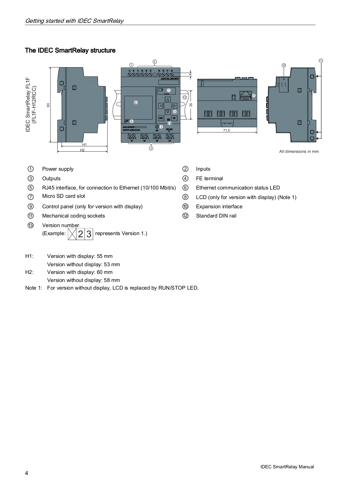
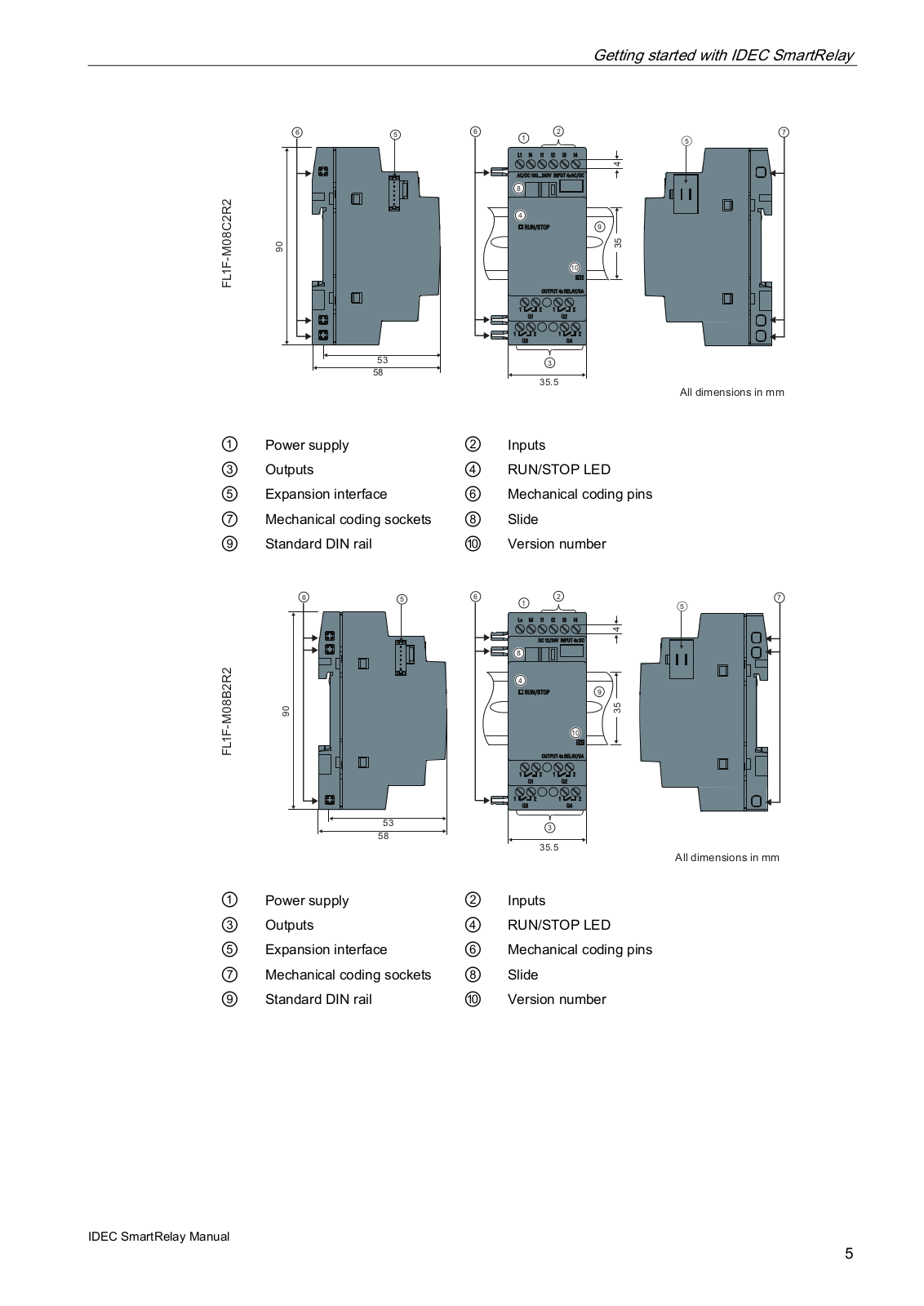
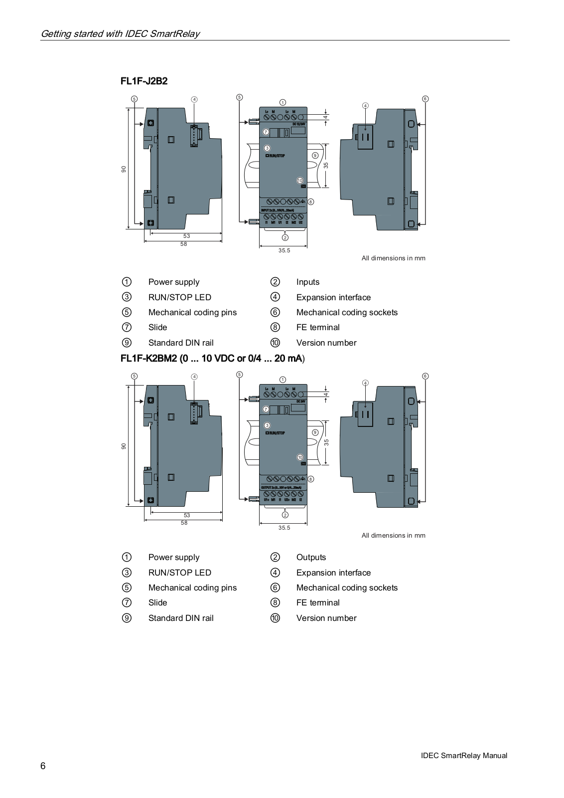
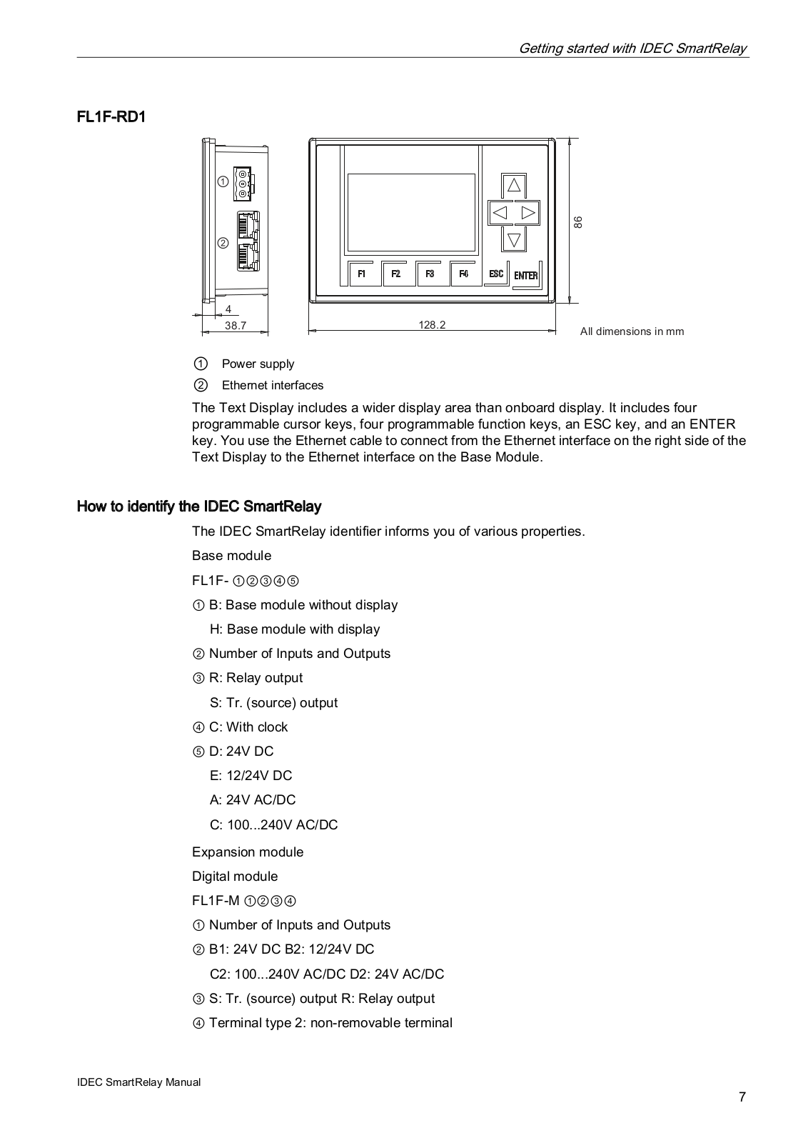
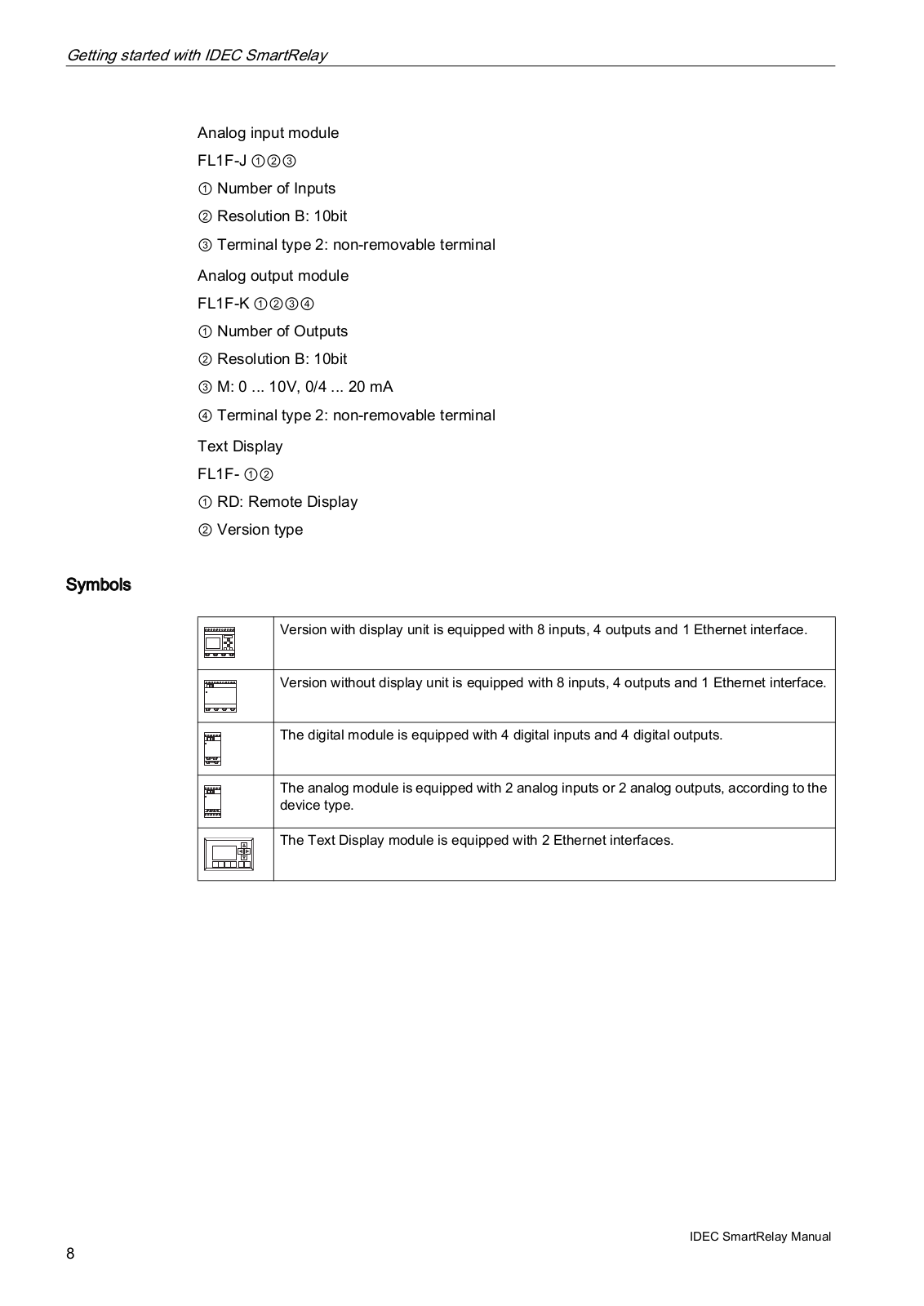
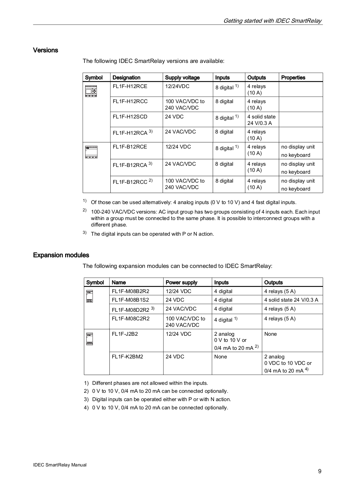
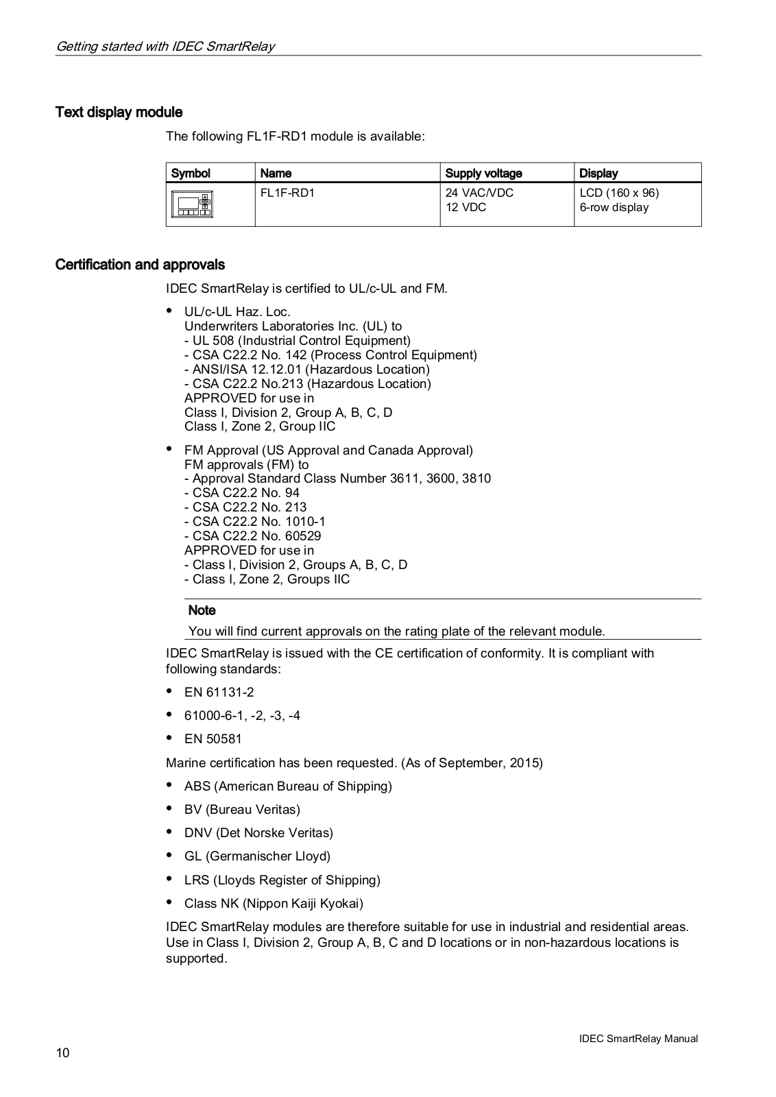
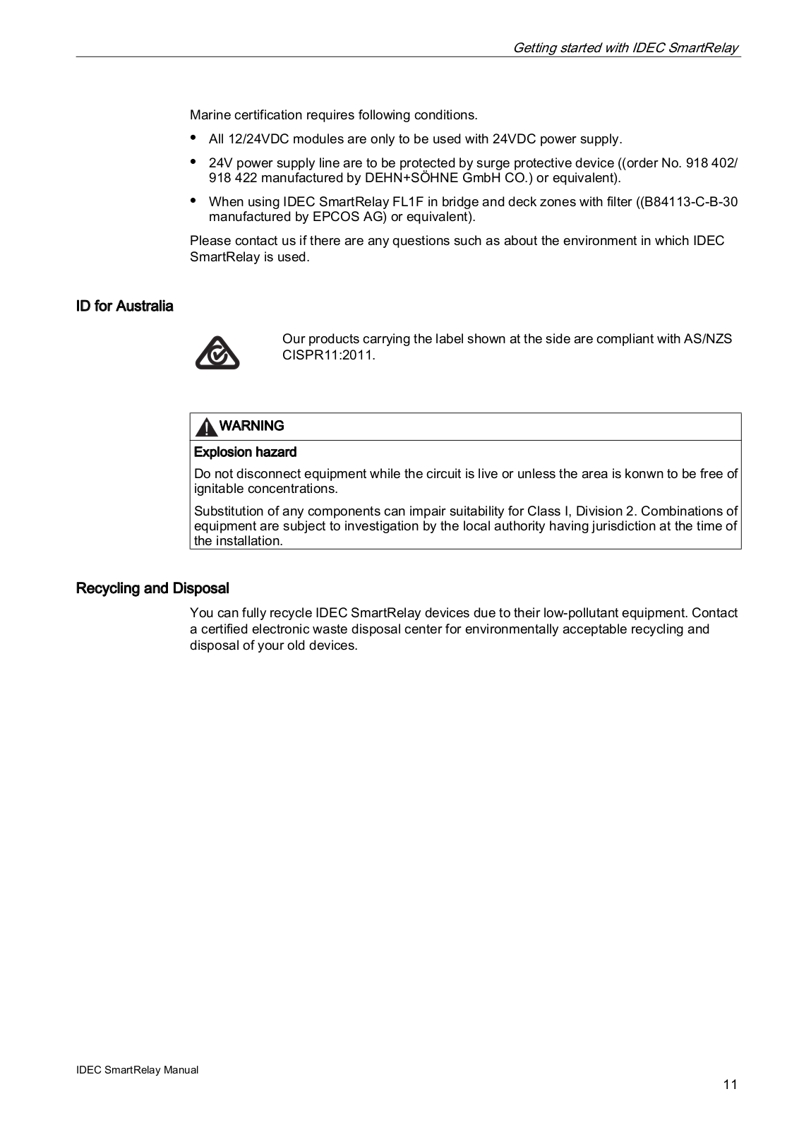
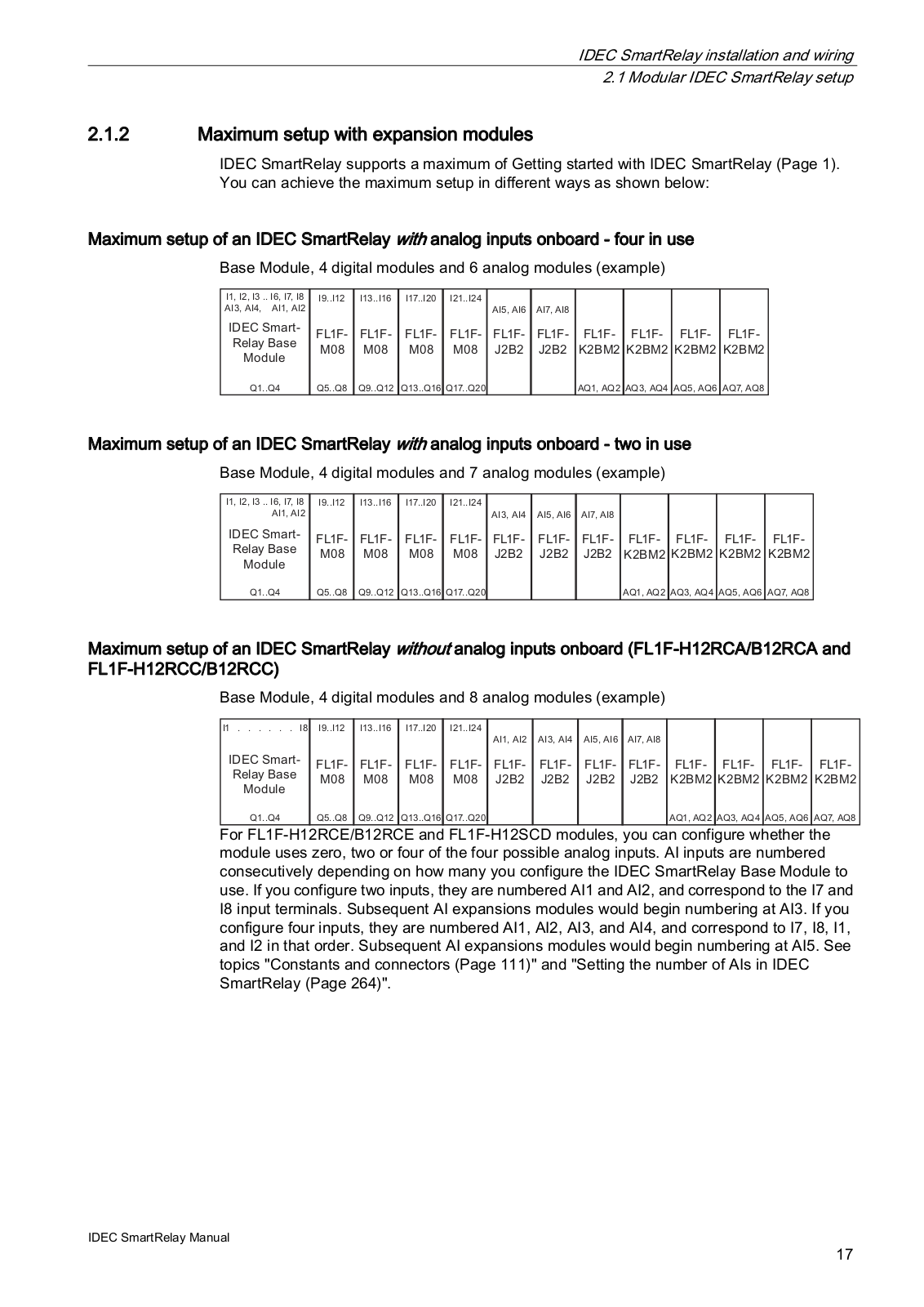
FL1F Series
Users Manual
339 pgs
39.45 Mb
0
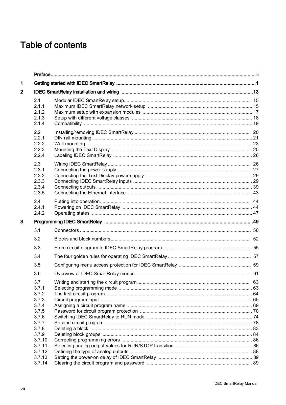
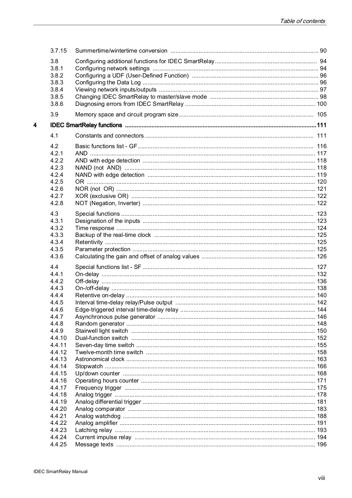
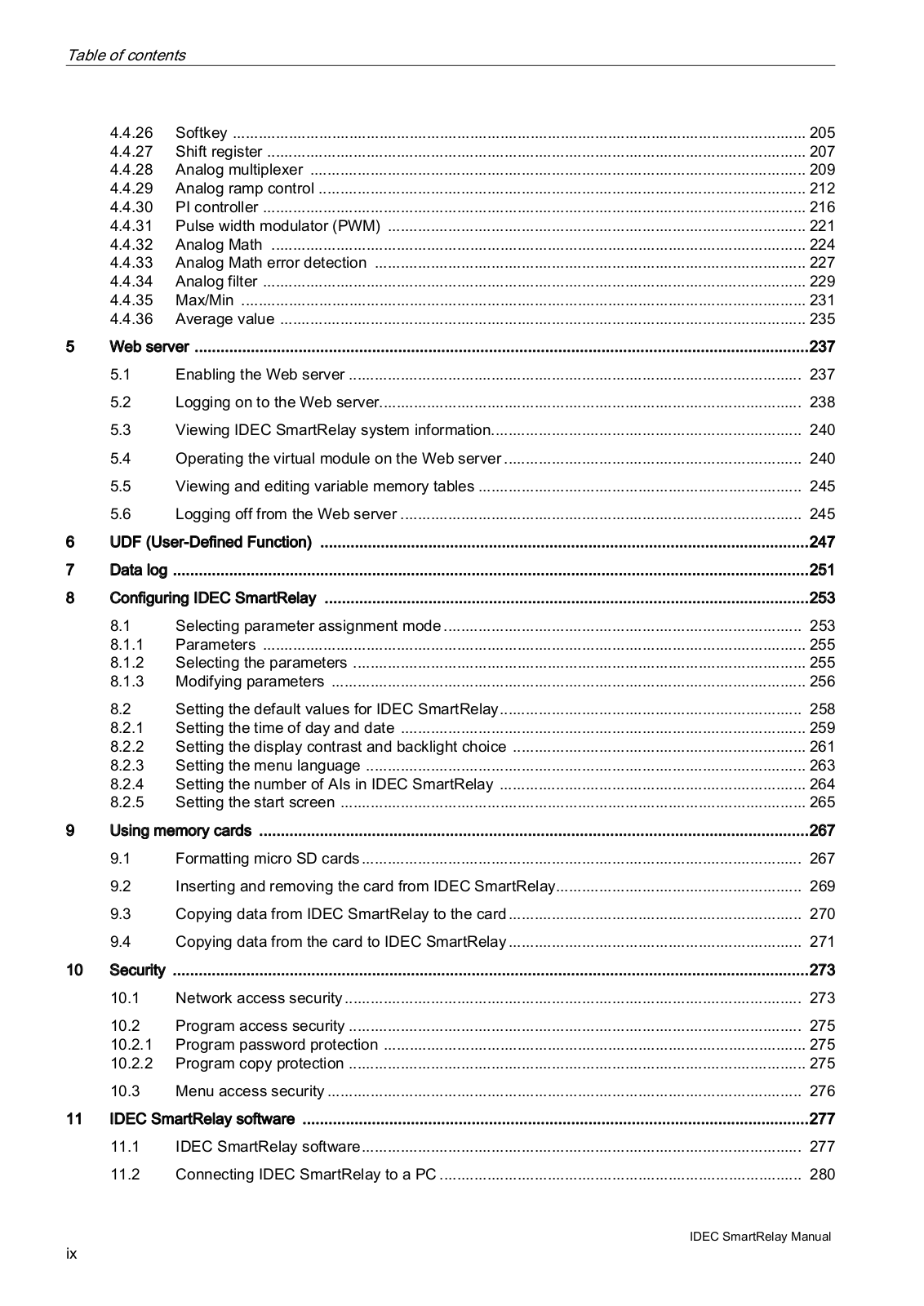
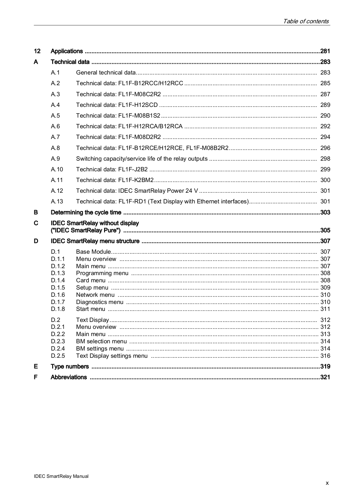
Table of contents
Loading...
IDEC FL1F Series Users Manual
...
IDEC Users Manual
Download
Specifications and Main Features
Frequently Asked Questions
User Manual
Download
Loading...
+
hidden pages
Unhide
You need points to download manuals.
1 point = 1 manual.
You can buy points or you can get point for every manual you upload.
Buy points
Upload your manuals
 Loading...