

Page 1
B-1090(3)
Page 2

Revision History
Date Manual No. Description
November, 2008 B-1090(0)
December, 2008 B-1090(1)
February, 2009 B-1090(2)
July, 2009 B-1090(3) Deleting the circuit program and password “Note”
First print
Sensor connections for IDEC SmartRelay:
FL1E-H12RCA / FL1E-B12RCA /
FL1E-H12RCE / FL1E-B12RCE / FL1E-H12SND
• Compatibility (FL1C-PM3 memory cartridge in FL1E)
• Compatibility (FL1E-PM4 memory cartridge in old er
IDEC SmartRelay modules)
Page 3
Safety guidelines
This manual contains notices you have to observe in order
to ensure your personal safety, as well as to prevent damage
to property. The notices referring to your personal safety are
highlighted in the manual by a safety alert symbol, notices
referring to property damage only have no safety alert
symbol. The notices shown below are graded according to
the degree of danger.
Danger
!
!
!
indicates that death or severe personal injury will result if proper
precautions are not taken.
Warning
indicates that death or severe personal injury may result if proper
precautions are not taken.
Caution
with a safety alert symbol indicates that minor personal injury can
result if proper precautions are not taken.
Caution
without a safety alert symbol indicates that property damage can
result if proper precautions are not taken.
Note
indicates that an unintended result or situation can occur if the corresponding notice is not taken into account.
If more than one degree of danger is present, the warning
notice representing the highest degree of danger will be used.
A notice warning of injury to persons with a safety alert symbol
may also include a warning relating to property damage.
IDEC SmartRelay Manual i
Page 4

Qualified Personnel
The device/system may only be set up and used in
conjunction with this documentation. Commissioning and
operation of a device/system may only be performed by
qualified personnel. Within the context of the safety notices
in this documentation qualified persons are defined as
persons who are authorized to commission, ground and
label devices, systems and circuits in accordance with
established safety practices and standards.
Prescribed Usage
Note the following:
Warning
!
Copyright IDEC CORPORATION All rights reserved
This device and its components may only be used for the
applications described in the catalog or the technical description,
and only in connection with devices or components from other
manufacturers which have been approved or recommended by
IDEC.
Correct, reliable operation of the product requires proper transport,
storage, positioning and assembly as well as careful operation and
maintenance.
The reproduction, distribution or use of this document or its
contents is not permitted without express written authority.
Offenders will be liable for damages. All rights reserved, in
particular in the event of patents being granted or the
registration of a utility model or design.
Disclaim of Liability
We have reviewed the contents of this publication to ensure
consistency with the hardware and software described.
Since variance cannot be precluded entirely, we cannot
guarantee full consistency. However, the information in this
publication is reviewed regularly and any necessary
corrections are included in subsequent editions.
ii IDEC SmartRelay Manual
Page 5

Preface
Dear customer
We thank you for purchasing IDEC SmartRelay and
congratulate you on your decision. With IDEC SmartRelay
you have acquired a logic module that meets the stringent
quality requirements of ISO 9001.
IDEC SmartRelay can be used in many fields of applications.
Due to its high functionality and easy operation, IDEC
SmartRelay offers you the utmost efficiency for almost any
application.
Purpose of this manual
This IDEC SmartRelay manual provides you with information
about the creation of circuit programs, about the installation
and use of FL1E IDEC SmartRelay base modules, the Text
Display and the IDEC SmartRelay expansion modules, and
about their compatibility with the previous FL1A–FL1D
versions (FL1x are the last four characters of the order
number of the base modules and differentiate the device
series).
IDEC SmartRelay’s place in information technology
The wiring information in your IDEC SmartRelay manual is
also found in the IDEC SmartRelay Product Info included
with all devices. For further information on programming the
IDEC SmartRelay on your PC, refer to the Online Help for
WindLGC.
WindLGC is the programming software for PCs. It runs
under Windows
get started with IDEC SmartRelay and to write, test, print out
and archive your programs, independent of the IDEC
SmartRelay.
Guide
The manual is divided into 8 chapters:
• Getting started with IDEC SmartRelay
• IDEC SmartRelay installation and wiring
• Programming IDEC SmartRelay
• IDEC SmartRelay functions
• Configuring IDEC SmartRelay
• IDEC SmartRelay memory and battery cartridges
• IDEC SmartRelay software
• Applications
(including Windows Vista). It helps you to
Preface
IDEC SmartRelay Manual iii
Page 6

Preface
Valid range of this manual
The manual applies to devices of series FL1E.
New features of the FL1E IDEC SmartRelay device series
• The Text Display provides an additional display device for
messages, and contains four cursor keys and four functions
keys that can be used in the circuit program.
• The new IDEC SmartRelay Battery cartridge and the
IDEC SmartRelay Combined Memory/Battery cartridge
provide up to two years of backup time for the real-time
clock. The new IDEC SmartRelay Memory cartridge and
the Combined Memory/Battery cartridge provide 32
Kbytes memory space: four times the memory space of
the old Memory cartridge (brown).
• Additional optional analog inputs and fast digital inputs are
available on some of the FL1E IDEC SmartRelay base
modules.
• FL1E IDEC SmartRelay menus can be displayed in ten
supported languages. You have a configuration choice to
specify the language for IDEC SmartRelay menus.
• New instruction blocks are available: Pulse Width Modulator
(PWM), Analog Math, and Analog Math Error Detection.
• Message texts can tick on and off the display; can include
bar graphs, can switch between two character sets, and
can be displayed on either the IDEC SmartRelay Display,
the Text Display, or both. Full editing capabilities are
available from WindLGC; editing from the IDEC
SmartRelay base module is limited to simple text. See
section 2.1.3 for further details.
• USB PC cable between a PC and IDEC SmartRelay base
module is provided.
• You can now have up to 200 program blocks in your
circuit program.
iv IDEC SmartRelay Manual
Page 7

Preface
Additional differences compared to previous devices (FL1A to
FL1D)
• Extended set of reference parameters for function blocks.
• Enhancements to up/down counter, Operating hours
counter, Twelve-month time switch and analog watchdog
instruction blocks.
• You can find information on compatibility of IDEC SmartRelay FL1E to previous devices at section 2.1.3.
Additional support
At our Internet address
http://smart.idec.com/
you can quickly and easily find answers to your queries
about IDEC SmartRelay.
IDEC SmartRelay Manual v
Page 8

Contents
Preface ............................................................iii
Contents..........................................................vi
1 Getting started with IDEC SmartRelay ..........1
2 IDEC SmartRelay installation and wiring ....15
2.1 Modular IDEC SmartRelay setup ........................................ 18
2.1.1 Maximum setup................................................................... 18
2.1.2 Setup with different voltage classes.................................... 20
2.1.3 Compatibility ....................................................................... 21
2.2 Installing/removing IDEC SmartRelay................................ 22
2.2.1 DIN rail mounting ................................................................ 23
2.2.2 Wall-mounting ..................................................................... 26
2.2.3 Mounting the Text Display ................................................... 27
2.3 Wiring IDEC SmartRelay ..................................................... 28
2.3.1 Connecting the power supply.............................................. 29
2.3.2 Connecting the Text Display power supply ......................... 30
2.3.3 Connecting IDEC SmartRelay inputs.................................. 31
2.3.4 Connecting outputs............................................................. 40
2.3.5 Connecting the AS interface bus ........................................ 43
2.4 Putting into operation.......................................................... 45
2.4.1 Switching on the IDEC SmartRelay/Power On ................... 45
2.4.2 Operating states.................................................................. 48
3 Programming IDEC SmartRelay ..................51
3.1 Connectors ........................................................................... 52
3.2 Blocks and block numbers ................................................. 54
3.3 From circuit diagram to IDEC SmartRelay program......... 57
3.4 The four golden rules for operating IDEC SmartRelay..... 60
3.5 Overview of IDEC SmartRelay menus................................ 62
3.6 Writing and starting the circuit program ........................... 63
vi IDEC SmartRelay Manual
Page 9

3.6.1 Selecting programming mode............................................. 63
3.6.2 The first circuit program ...................................................... 64
3.6.3 Circuit program input .......................................................... 66
3.6.4 Assigning a circuit program name ...................................... 71
3.6.5 Password ............................................................................ 72
3.6.6 Switching IDEC SmartRelay to RUN mode ........................ 75
3.6.7 Second circuit program ....................................................... 77
3.6.8 Deleting a block .................................................................. 83
3.6.9 Deleting block groups ......................................................... 84
3.6.10 Correcting programming errors........................................... 85
3.6.11 Selecting analog output values for RUN/STOP transition ... 85
3.6.12 Defining the type of analog outputs .................................... 86
3.6.13 Deleting the circuit program and password......................... 87
3.6.14 Summertime/wintertime conversion ................................... 88
3.6.15 Synchronization .................................................................. 92
3.7 Memory space and circuit program size ........................... 94
4 IDEC SmartRelay functions ....................... 101
4.1 Constants and connectors - Co ....................................... 102
4.2 Basic functions list - GF.................................................... 106
4.2.1 AND .................................................................................. 107
4.2.2 AND with Edge Detection ................................................. 108
4.2.3 NAND (not AND).............................................................. 108
4.2.4 NAND with Edge Detection............................................... 109
4.2.5 OR .................................................................................... 110
4.2.6 NOR (not OR) .................................................................. 111
4.2.7 XOR (exclusive OR).......................................................... 112
4.2.8 NOT (Negation, Inverter) .................................................. 112
4.3 Special functions ............................................................... 113
4.3.1 Designation of the inputs .................................................. 113
4.3.2 Time response .................................................................. 114
4.3.3 Backup of the real-time clock............................................ 115
4.3.4 Retentivity ......................................................................... 116
4.3.5 Parameter protection ........................................................ 116
4.3.6 Calculating the gain and offset of analog values .............. 117
4.4 Special functions list - SF ................................................. 120
4.4.1 On-delay ........................................................................... 123
IDEC SmartRelay Manual vii
Page 10

4.4.2 Off-delay ........................................................................... 127
4.4.3 On-/Off-delay .................................................................... 128
4.4.4 Retentive on-delay ............................................................ 130
4.4.5 Interval time-delay relay/Pulse output............................... 131
4.4.6 Edge-triggered interval time-delay relay ........................... 132
4.4.7 Asynchronous pulse generator ......................................... 134
4.4.8 Random generator ............................................................ 136
4.4.9 Stairwell Light Switch ........................................................ 138
4.4.10 Dual-function switch.......................................................... 140
4.4.11 Seven-day time switch ...................................................... 142
4.4.12 Twelve-month time switch ................................................. 147
4.4.13 Up/down counter............................................................... 153
4.4.14 Operating hours counter ................................................... 156
4.4.15 Frequency trigger.............................................................. 160
4.4.16 Analog trigger ................................................................... 163
4.4.17 Analog differential trigger .................................................. 166
4.4.18 Analog comparator............................................................ 169
4.4.19 Analog watchdog .............................................................. 174
4.4.20 Analog amplifier ................................................................ 177
4.4.21 Latching relay.................................................................... 179
4.4.22 Current impulse relay ....................................................... 180
4.4.23 Message texts................................................................... 182
4.4.24 Softkey.............................................................................. 194
4.4.25 Shift register...................................................................... 197
4.4.26 Analog Multiplexer............................................................. 199
4.4.27 Analog Ramp Control........................................................ 201
4.4.28 PI controller....................................................................... 205
4.4.29 Pulse Width Modulator (PWM).......................................... 211
4.4.30 Analog math...................................................................... 214
4.4.31 Analog math error detection.............................................. 219
5 Configuring IDEC SmartRelay....................223
5.1 Selecting parameter assignment mode ........................... 224
5.1.1 Parameters ....................................................................... 225
5.1.2 Selecting the parameters.................................................. 226
5.1.3 Modifying parameters ....................................................... 227
5.2 Setting the default values for IDEC SmartRelay ............. 229
5.2.1 Setting the time of day and date (FL1E-H12RC...) ...........230
5.2.2 Setting the display contrast and backlight choice ............. 231
viii IDEC SmartRelay Manual
Page 11

5.2.3 Setting the menu language............................................... 233
5.2.4 Setting the number of AIs in the base module .................. 234
5.2.5 Setting the start screen..................................................... 235
6 IDEC SmartRelay memory
and battery cartridge (card)....................... 237
6.1 Security function (CopyProtect)....................................... 240
6.2 Inserting and removing memory and battery
cartridges ........................................................................... 242
6.3 Copying data from IDEC SmartRelay to the memory
cartridge ............................................................................. 244
6.4 Copying data from the memory cartridge to IDEC
SmartRelay ......................................................................... 246
7 IDEC SmartRelay software ........................ 249
7.1 Connecting IDEC SmartRelay to a PC ............................. 251
8 Applications ................................................ 253
8.1 Stairway or corridor lighting............................................. 255
8.1.1 Requirements for a stairway lighting system .................... 255
8.1.2 Previous solution .............................................................. 255
8.1.3 Lighting system with IDEC SmartRelay............................ 256
8.1.4 Special features and expansion options ........................... 258
8.2 Automatic door .................................................................. 259
8.2.1 Requirements of an automatic door.................................. 259
8.2.2 Conventional solution........................................................ 260
8.2.3 Door control system with IDEC SmartRelay..................... 260
8.2.4 Special features and expansion options ........................... 263
8.2.5 Extended solution with FL1E-H12RCC............................. 263
8.3 Air-conditioning system.................................................... 266
8.3.1 Requirements for an air-conditioning system.................... 266
8.3.2 Advantages of using IDEC SmartRelay............................ 269
8.4 Factory door ....................................................................... 271
8.4.1 Requirements for a gate control system ........................... 271
8.4.2 Previous solution .............................................................. 272
IDEC SmartRelay Manual ix
Page 12

8.4.3 Extended IDEC SmartRelay solution................................ 274
8.5 Centralized control and monitoring of
several factory doors......................................................... 275
8.5.1 Requirements for a gate control system ...........................276
8.6 Luminous rows .................................................................. 279
8.6.1 Requirements for a lighting system................................... 279
8.6.2 Previous solution............................................................... 280
8.6.3 Luminous row control system with FL1E-H12RCC........... 281
8.7 Service water pump ........................................................... 283
8.7.1 Requirements for a control system of a service
water pump ....................................................................... 284
8.7.2 Previous solution............................................................... 284
8.7.3 Service water pump system with FL1E-H12RCC .............285
8.7.4 Special features and expansions ...................................... 286
A Technical data .............................................287
A.1 General technical data....................................................... 287
A.2 Technical data: FL1E-H12RCC/FL1E-B12RCC ................ 289
A.3 Technical data: FL1B-M08C2R2 ....................................... 292
A.4 Technical data: FL1E-H12SND.......................................... 295
A.5 Technical data: FL1B-M08B1S2 ....................................... 297
A.6 Technical data: FL1E-H12RCA/FL1E-B12RCA ................ 299
A.7 Technical data: FL1B-M08D2R2 ....................................... 302
A.8 Technical data: FL1E-H12RCE/
FL1E-B12RCE and FL1B-M08B2R2 .................................. 304
A.9 Switching capacity and service life of the
relay outputs ...................................................................... 307
A.10 Technical data: FL1B-J2B2 ............................................... 308
A.11 Technical data: FL1D-K2B2 .............................................. 309
A.12 Technical data: Text Display............................................. 310
x IDEC SmartRelay Manual
Page 13

B Determining the cycle time........................ 311
C IDEC SmartRelay without display ............ 315
D IDEC SmartRelay menu structure ............. 319
D.1 IDEC SmartRelay base module ........................................ 319
D.2 Text Display........................................................................ 321
E Type Numbers............................................. 323
Index ............................................................ 325
IDEC SmartRelay Manual xi
Page 14

xii IDEC SmartRelay Manual
Page 15

Getting started with IDEC SmartRelay
Here’s IDEC SmartRelay
IDEC SmartRelay is a universal logic module made by IDEC
that integrates:
• Controls
• Operator and display panel with background lighting
• Power supply
• Interface for expansion modules
• Interface for the memory cartridge, battery cartridge,
combined memory/battery cartridge or a PC cable
• Interface for an optional text display (TD) module
• Pre-configured standard functions, for example, on-and
off-delays, current impulse relay and softkey
•Timers
• Digital and analog memory markers
• Inputs and outputs, according to the device type
What IDEC SmartRelay can do for you
IDEC SmartRelay offers solutions for domestic and
installation engineering applications such as stairway
lighting, external lighting, sun blinds, shutters, shop window
lighting and more; switch cabinet engineering, as well as for
mechanical and apparatus engineering such as gate control
systems, air-conditioning systems, rand ainwater pumps.
IDEC SmartRelay can also be implemented for special
control systems in conservatories or greenhouses, for
control signal processing and, by connecting a
communication module such as an AS-i module, for
distributed local controlling of machines and processes.
Special versions without operator panel and display unit are
available for series production applications in small machine,
apparatus, switching cabinet and installation engineering.
1
IDEC SmartRelay Manual 1
Page 16

Getting started with IDEC SmartRelay
Which devices are available?
IDEC SmartRelay Base is available in two voltage classes:
• Class 1 ≤ 24 V, i.e. 12 V DC, 24 V DC, 24 V AC
• Class 2 > 24 V, i.e. 100...240 V AC/DC
IDEC SmartRelay Base is available in two versions:
• With display: 8 inputs and 4 outputs
• Without display (”IDEC SmartRelay Pure”): 8 inputs and
4 outputs
Each version is integrated into four subunits, is equipped
with an expansion interface and Text Display interface and
provides 39 pre-configured standard and special function
blocks for the creation of your circuit program.
Which expansion modules are available?
• IDEC SmartRelay digital modules are available for
operation with 12 V DC, 24 V AC/DC and 100...240 V AC/
DC, and are equipped with four inputs and four outputs.
• IDEC SmartRelay analog modules are available for
operation with 24 V DC and some with 12 V DC,
depending on the specific module. Each is equipped with
two analog inputs or two analog outputs.
The digital/analog modules are integrated in two or four
subunits. Each one is equipped with two expansion
interfaces for connecting additional modules.
Which display modules are available?
• IDEC SmartRelay Base with display
• Text Display
2 IDEC SmartRelay Manual
Page 17

Getting started with IDEC SmartRelay
Features of the Text Display
The Text Display is available with the FL1E series. It
provides an additional display that is wider than the Base
module. It has four function keys that you can program in
your circuit program as inputs. Like the IDEC SmartRelay
Base module, it has four cursor keys, an ESC and OK key
that you can also program in your circuit program and use for
navigation on the Text Display.
You can create and download a power-up screen for the
Text Display from WindLGC. This screen displays briefly
when you initially power on the Text Display. You can also
upload the power-up screen from the Text Display to
WindLGC.
The menus for the Text Display are shown in Appendix
section D.2. You configure the settings for the Text Display
independently from the IDEC SmartRelay Base module. The
settings can be different.
Which communication modules are available?
• IDEC SmartRelay communication module (CM) AS
interface, which is described in more detail in a separate
documentation.
The communication module has four virtual inputs and
outputs, and acts as an interface between an ASInterface system and an IDEC SmartRelay system. The
module enables four data bits to be transferred from the
IDEC SmartRelay base module to the AS-Interface
system and vice versa.
IDEC SmartRelay Manual 3
Page 18

Getting started with IDEC SmartRelay
It’s your choice
The various IDEC SmartRelay Base versions, expansion
modules, Text Display and communication modules offer
you a highly flexible and adaptive system to suit your specific
tasks.
The IDEC SmartRelay system offers you many solutions
such as for small domestic installations, simple automation
tasks, and even complex engineering tasks involving its
integration into a bus system (e.g. communication module
AS interface).
Note
IDEC SmartRelay base module may only be equipped with
expansion modules of the same voltage class. Mechanical
encoding pins in the housing prevent you from connecting devices
of a different voltage class.
Exception: The left-hand interface of an analog module or
communication module is galvanically isolated.
This type of expansion module can therefore be connected to
devices of a different voltage class. See also Chapter 2.1.
A Text Display, if used, can be connected only to an FL1E IDEC
SmartRelay base module.
Each IDEC SmartRelay base module supports the following
connections for the creation of the circuit program, regardless of the
number of connected modules:
• Inputs 11 to I24
• Analog inputs AI1 to AI8
• Outputs Q1 to Q16
• Analog outputs AQ1 and AQ2
• Memory Markers M1 to M27:
- M8: Startup marker
- M25: Backlight flag: IDEC SmartRelay Display
- M26: Backlight flag: Text Display
- M27: Message text character set flag
• Analog Memory Markers AM1 to AM6
• Shift register bits S1 to S8
• 4 cursor keys
• 16 blank outputs X1 to X16
4 IDEC SmartRelay Manual
Page 19
Getting started with IDEC SmartRelay
The IDEC SmartRelay structure
IDEC SmartRelay Base
IDEC SmartRelay
expansion module
L1 N
6
1 2 1 2 1 2 1 2
Q1 Q2 Q3 Q4
(e.g.: FL1E-H12RCC)
L1 N I2 I3 I4I1
1 2 1 2
1 2 1 2
Q3
(e.g.: FL1B-M08C2R2)
Power supply Control panel
1 5 9
I5 I6I2 I3 I4I1
72
RUN/STOP
Q1 Q2
Q4
36
(not for FL1EB12...)
Inputs LCD
2 6 10
(not for FL1EB12...)
Outputs RUN/STOP
3 7 11
indicator
Module slot
4 8 12
with cap
Expansion
interface
I7 I8
4
53
4
53
53
Mechanical coding
pins
Mechanical coding
sockets
Slide
Text Display
cable connector
Version number
13
(example:
represents Version 1.)
09
55
0
9
X 2
3 4
IDEC SmartRelay Manual 5
Page 20
Getting started with IDEC SmartRelay
C
S
L+ M
6
1 2 1 2 1 2 1 2
Q1 Q2 Q3 Q4
IDEC SmartRelay Base
(e.g.: FL1E-H12RCE)
martRelay
IDE
expansion module
(e.g.: FL1B-M08B2R2)
Power supply Control panel
1 5 9
72
L+ M I2 I3 I4I1
RUN/STOP
1 2 1 2
Q1 Q2
1 2 1 2
Q3 Q4
36
(not for FL1EB12...)
Inputs LCD
2 6 10
(not for FL1EB12...)
Outputs RUN/STOP
3 7 11
indicator
Module slot
4 8
with cap
Expansion
interface
I7 I8
I5 I6I2 I3 I4I1
5
4
4
53
55
4
53
53
09
09
Mechanical coding
pins
Mechanical coding
sockets
Slide
Text Display
12
cable connector
Version number
13
6 IDEC SmartRelay Manual
Page 21
FL1B-J2B2
Getting started with IDEC SmartRelay
L+ M
L+ M
4
RUN/STOP
PE
INPUT2x(0..10V/0..20mA)
I1
M1 U1 M2 U2I2
36 53
Power supply Mechanical
1 9 12
coding pins
Inputs Mechanical
2 10
coding sockets
RUN/STOP
7 11 13
Slide Version number
indicator
Expansion interface
8
FL1D-K2B2
53
PE terminal, for
connecting earth and
the shielding of
analog measuring
cables.
09
Power supply Expansion
1 8 11
Slide
interface
Outputs Mechanical
2 9 12
coding pins
RUN/STOP
7 10 13
indicator
Mechanical
coding sockets
PE terminal, for
connecting earth
Version number
IDEC SmartRelay Manual 7
Page 22
Getting started with IDEC SmartRelay
Text Display
c Communication interface
d Power supply
The Text Display includes a wider display area than the
IDEC SmartRelay Display. It includes four programmable
cursor keys, four programmable function keys, and an ESC
and OK key. You use the included Text Display cable to
connect from the communication interface on the right side
of the Text Display to the corresponding interface on the left
side of the IDEC SmartRelay base module.
How to identify the IDEC SmartRelay
The IDEC SmartRelay identifier informs you of various
properties.
Base module
FL1E-cdefg
c B: Base module without display
H: Base module with display
d Number of Inputs and Outputs
e R: Relay output S: Tr. (source) output
f C: With clock N: Without clock
g D: 24V DC E: 12/24V DC A: 24V AC/DC
B: 100...240V AC C: 100...240V AC/DC
8 IDEC SmartRelay Manual
Page 23

Getting started with IDEC SmartRelay
Expansion module
Digital module
FL1B-Mcdef
c Number of Inputs and Outputs
d B1: 24V DC B2: 12/24V DC
C2: 100...240V AC/DC D2: 24V AC/DC
e S: Tr. (source) output R: Relay output
f Terminal type 2: non-removable terminal
Analog input module
FL1B-Jcde
c Number of Inputs
d Resolution B: 10bit
e Terminal type 2: non-removable terminal
Analog output module
FL1D-Kcde
c Number of Outputs
d Resolution B: 10bit
e Terminal type 2: non-removable terminal
Communication module
FL1B-cdef
c C: Communication module
d L1: LONWORKS AS: AS-Interface
e blank: AS-Interface rated voltage (30V DC) C1: 24V AC/
DC
f Terminal type 2: non-removable terminal
Text Display
FL1E-cd
c RD: Remote Display
d Version type
IDEC SmartRelay Manual 9
Page 24
Getting started with IDEC SmartRelay
Symbols
Version with display unit is equipped with 8 inputs and 4 outputs
Version without display unit is equipped with 8 inputs and 4 outputs
The digital module is equipped with 4 digital inputs and 4 digital
outputs
The analog module is equipped with 2 analog inputs or two analog
outputs, according to the device type
The communication module (CM); for example, AS Interface is
equipped with 4 virtual inputs and 4 virtual outputs
The Text Display
10 IDEC SmartRelay Manual
Page 25
Getting started with IDEC SmartRelay
Versions
The following IDEC SmartRelay versions are available:
Symbol Designation Supply
voltage
FL1E-H12RCE 12/24 V DC 8 digital
FL1E-H12SND 24 V DC 8 digital
FL1E-H12RCA
(3)
24 V AC/
24 V DC
FL1E-H12RCC
(2)
100...240 V
AC/DC
FL1E-B12RCE 12/24 V DC 8 digital
FL1E-B12RCA
(3)
24 V AC /
24 V DC
FL1E-B12RCC
(2)
100...240 V
AC/DC
(1): Of those can be used alternatively: 4 analog inputs (0 ... 10V) and 4 fast inputs.
(2): AC versions: Two groups consisting of 4 inputs each. Each input within a group
must be connected to the same phase. It is possible to interconnect groups with
a different phase.
(3): The digital inputs can be operated with P or N action.
Inputs Outputs Properties
(1)
4 relays
(10 A)
(1)
4 solid state
no clock
24V / 0.3A
8 digital 4 relays
(10A)
8 digital 4 relays
(10A)
(1)
4 relays
(10A)
8 digital 4 relays
(10A)
8 digital 4 relays
(10A)
no display unit
no keyboard
no display unit
no keyboard
no display unit
no keyboard
IDEC SmartRelay Manual 11
Page 26
Getting started with IDEC SmartRelay
Expansion modules
The following expansion modules can be connected to IDEC
SmartRelay:
Symbol Name Power supply Inputs Outputs
FL1B-M08B2R2 12/24 V DC 4 digital 4 relays (5A)
FL1B-M08B1S2 24 V DC 4 digital 4 solid state 24V
/ 0.3A
(3)
FL1B-M08D2R2
FL1B-M08C2R2 100...240 V
FL1B-J2B2 12/24 V DC 2 analog
FL1D-K2B2 24 V DC none 2 analog
(1): Different phases are not allowed within the inputs.
(2): 0 ... 10 V, 0 ... 20 mA can be connected optionally.
(3): Digital inputs can be operated either with P or with N action.
24 V AC/DC 4 digital 4 relays (5A)
(1)
AC/DC
4 digital
0 ... 10V or
0 ... 20mA
4 relays (5A)
none
(2)
0 ... 10 V DC
Communication modules
The following communication modules can be connected
to IDEC SmartRelay:
Symbol Name Power supply Inputs Outputs
IDEC SmartRelay CM AS
Interface
30 V DC the next four inputs
after the physical
inputs of IDEC
SmartRelay
(I
... I
)
n
n+3
the next four
outputs after the
physical outputs of
IDEC SmartRelay
(Q
... Q
n
n+3
)
Text Display Module
The following Text Display module is available:
Symbol Name Supply voltage Display
Text Display 24 V AC/DC
12 V DC
12 IDEC SmartRelay Manual
LCD (128 x 64)
4-row display
Page 27

Certification and approvals
IDEC SmartRelay is certified to cULus and FM.
• cULus Haz. Loc.
Underwriters Laboratories Inc. (UL) to
- UL 508 (Industrial Control Equipment)
- CSA C22.2 No. 142 (Process Control Equipment)
- UL 1604 (Hazardous Location)
- CSA–213 (Hazardous Location)
APPROVED for use in
Class I, Division 2, Group A, B, C, D Tx
Class I, Zone 2, AEx, nC, IIC, Tx
Class I, Zone 2, Ex, nC, IIC, Tx
• FM Approval
Factory Mutual Research (FM) to
Approval Standard Class Number 3611, 3600, 3810
APPROVED for use in
Class I, Division 2, Group A, B, C, D Tx
Class I, Zone 2, Group IIC Tx
For further information, see our Internet address
(URL: http://www.idec.com/usen)
Note
You will find current approvals on the rating plate of the relevant
module.
Getting started with IDEC SmartRelay
IDEC SmartRelay is issued with the CE Certificate of
Conformity. It is compliant with IEC 60730-1 and IEC 611312 and interference-proof to EN 55011, Limit Class B.
Marine certification has been requested.
• ABS (American Bureau of Shipping)
• BV (Bureau Veritas)
• DNV (Det Norske Veritas)
• GL (Germanischer Lloyd)
• LRS (Lloyds Register of Shipping)
• Class NK (Nippon Kaiji Kyokai)
IDEC SmartRelay modules are therefore suitable for use in
industrial and residential areas. Use in Class I, Division 2,
Group A, B, C and D locations or in non-hazardous locations
is supported.
IDEC SmartRelay Manual 13
Page 28

Getting started with IDEC SmartRelay
Marine certification requires the surge protective device what
manufactured by DEHN+SÖHNE GmbH+Co., in a case of
12/24V DC or 24V DC power line. The required Type No. and
Part No.: BVT AD 24, 918 402. See Note on page 288.
For further information, see our Internet address
(URL: http://www.idec.com/usen)
ID for Australia
✔
!
Our products carrying the label shown at the side are compliant
with AS/NZS 2064:1997 (Class A) standard.
Warning
Risk of death, personal injury or property damage can occur if you
do not follow safety precautions for hazardous locations.
In potentially explosive atmospheres, do not disconnect
connectors when the system is in RUN. Always switch off the
power supply to IDEC SmartRelay and its components before you
disconnect any connectors or components.
Substitution of components can impair suitability for Class I,
Division 2 locations. Combinations of equipment are subject to
investigation by the local authority having jurisdiction at the time of
installation.
Recycling and Disposal
IDEC SmartRelay units can be fully recycled, due to their
low-pollutant equipment. Contact a certified electronic waste
disposal center for environmentally acceptable recycling and
disposal of your old devices.
14 IDEC SmartRelay Manual
Page 29

IDEC SmartRelay installation and wiring
General guidelines
Please note the following guidelines for installing and wiring
your IDEC SmartRelay:
• Always ensure that the wiring of your IDEC SmartRelay
is compliant with current rules and standards. Also,
conform with all national and regional regulations when
you install and operate the devices. For information on
standards and regulations that apply to your specific
case, contact your local authorities.
• Always switch off power before you wire or install/remove
a module.
• Always use cables with appropriate conductor crosssections for the relevant current. You can wire IDEC
SmartRelay with cable conductor cross-sections from
1.5 mm
• Do not exceed the screw torque of the terminals. The
maximum torque is: 0.5 Nm, see Chapter 2.3.
• Keep the cabling as short as possible. If longer cables are
necessary, you should use shielded versions. You should
always route your cables in pairs: i.e. one neutral
conductor plus one phase conductor or signal line.
• Always keep separate:
- The AC wiring
- High-voltage DC circuits with high-frequency
- Low-voltage signal wiring
• Ensure that the wires are installed with appropriate strain
relief.
• Provide a suitable lightning surge arrester for cables
installed in hazardous areas.
• Do not connect an external power supply in parallel to the
output load of a DC output. This could develop a reverse
current at the output if you have not installed a diode or
similar barrier device.
• Reliable functioning of the equipment is only ensured with
certified components!
2
to 2.5 mm2; see Chapter 2.3.
switching cycles
2
Note
IDEC SmartRelay devices may only be installed and wired by
skilled personnel who are familiar with and follow general
engineering rules and relevant regulations and standards.
IDEC SmartRelay Manual 15
Page 30

IDEC SmartRelay installation and wiring
What you must note when installing
IDEC SmartRelay is designed for fixed and enclosed
installation in the housing or the control cabinet.
Warning
!
Death, serious bodily injury or considerable damage to property
can occur.
Modules of an IDEC SmartRelay are open facilities. This means
that you must install IDEC SmartRelay only in a housing or cabinet.
Allow access to the housings or cabinets only with the use of a key
or a tool and only allow access to authorized or approved
personnel.
It is permissible to operate IDEC SmartRelay from the front at any
time.
Safety of electronic control equipment
Introduction
The notes below apply regardless of the type or
manufacturer of the electronic control.
Reliability
Maximum reliability of IDEC SmartRelay devices and
components is achieved by implementing extensive and
cost-effective measures during development and
manufacture.
This includes the following:
• Use of high-quality components
• Worst-case design of all circuits
• Systematic and computer-aided testing of all
components
• Burn-in of all large-scale integrated circuits (e.g.
processors, memory, etc.)
• Measures preventing static charge when handling MOS
ICs
• Visual checks at different stages of manufacture
• Continuous heat-run test at elevated ambient
temperature over a period of several days
• Careful computer-controlled final testing
• Statistical evaluation of all returned systems and
components to enable the immediate initiation of suitable
corrective measures
16 IDEC SmartRelay Manual
Page 31

IDEC SmartRelay installation and wiring
• Monitoring of major control components, using online
tests (cyclic interrupt for the CPU, etc.)
These measures are referred to as basic measures.
Carrying out tests
You must, however, ensure safety in your plant.
Before finally commissioning a system, carry out complete
functional testing as well as all the necessary safety testing.
In testing, also include any predictable faults that can occur.
This means that you will avoid any danger to the plant or to
people during operation.
Risks
In all cases where the occurrence of failures can result in
material damage or injury to persons, special measures
must be taken to enhance the safety of the installation – and
therefore also of the situation. System-specific and special
regulations exist for such applications. They must be
observed on installing the control system (for example, VDE
0116 for burner control systems).
For electronic control equipment with a safety function, the
measures that have to be taken to prevent or rectify faults
are based on the risks involved in the installation. Beyond a
certain degree of hazard the basic measures mentioned
above are not sufficient. Additional measures must be
implemented and approved for the controller.
Important information
The instructions in the operating manual must be followed
exactly. Incorrect handling can render measures intended to
prevent dangerous faults ineffective, or generate additional
sources of danger.
IDEC SmartRelay Manual 17
Page 32

IDEC SmartRelay installation and wiring
2.1 Modular IDEC SmartRelay setup
2.1.1 Maximum setup
As defined in Chapter 1, IDEC SmartRelay supports a
maximum of 24 digital inputs, 8 analog inputs, 16 digital
outputs, and 2 analog outputs. You can achieve the
maximum setup in different ways as shown below:
Maximum setup of an IDEC SmartRelay with analog inputs - four
in use
(FL1E-H12RCE/FL1E-B12RCE and FL1E-H12SND)
IDEC SmartRelay base module, 4 digital modules, 2 analog
modules and 1 analog output module (example)
I1,I2, I3...I6 I7, I8
AI3,AI4, AI1,AI2
IDEC
SmartRelay
base module
Q1...Q4 Q5...Q8 Q9...Q12 Q13...Q16
I9...I12 I13...I16 I17...I20 I21...I24
FL1B-
FL1B-
FL1B-
M08
M08
M08
FL1BM08
AI5, AI6 AI7, AI8
FL1B-
FL1B-
J2B2
J2B2
FL1DK2B2
AQ1, AQ2
Maximum setup of an IDEC SmartRelay with analog inputs - two
in use
(FL1E-H12RCE/FL1E-B12RCE and FL1E-H12SND)
IDEC SmartRelay base module, 4 digital modules, 3 analog
modules and 1 analog output module (example)
I1,I2, I3...I6 I7, I8
IDEC
SmartRelay
base module
Q1...Q4 Q5...Q8 Q9...Q12 Q13...Q16
I9...I12 I13...I16 I17...I20 I21...I24
AI1,AI2
FL1B-
FL1B-
M08
M08
FL1BM08
FL1BM08
AI3, AI4
FL1BJ2B2
FL1BJ2B2
AI7, AI8AI5, AI6
FL1BJ2B2
FL1DK2B2
AQ1, AQ2
Maximum setup of an IDEC SmartRelay without analog inputs
(FL1E-H12RCA/FL1E-B12RCA and FL1E-H12RCC/FL1E-B12RCC)
IDEC SmartRelay base module, 4 digital modules, 4 analog
modules and 1 analog output module (example)
I1 . . . . . . . . . . I8
IDEC
SmartRelay
base module
Q1...Q4 Q5...Q8 Q9...Q12
I9...I12 I13...I16 I17...I20 I21...I24
FL1B-
FL1B-
FL1B-
M08
M08
M08
Q13..Q16
FL1BM08
AI1, AI2
FL1BJ2B2
AI3, AI4 AI5, AI6
FL1B-
FL1B-
J2B2
J2B2
AI7, AI8
FL1BJ2B2
FL1DK2B2
AQ1, AQ2
18 IDEC SmartRelay Manual
Page 33

IDEC SmartRelay installation and wiring
With any setup, you can plug in an analog output module,
which has the maximum of two analog outputs.
For FL1E-H12RCE/FL1E-B12RCE and FL1E-H12SND
modules, you can configure whether the module uses two or
four of the four possible analog inputs. AI inputs are
numbered consecutively depending on how many you
configure the base module to use. If you configure two
inputs, they are numbered AI1 and AI2, and correspond to
the I7 and I8 input terminals. Subsequent AI expansions
modules would begin numbering at AI3. If you configure four
inputs, they are numbered AI1, AI2, AI3, and AI4, and
correspond to I7, I8, I1, and I2 in that order. Subsequent AI
expansions modules would begin numbering at AI5. See
sections 4.1 and 5.2.4.
High-speed/optimal communication performance
For optimal and high-speed communication performance
between IDEC SmartRelay base module and the various
modules, we recommend that you install the digital modules
first, then the analog modules (examples above). (The
special function PI controller is an exception: the AI used for
the value PV should be on the IDEC SmartRelay base
module or an analog input module adjacent to the IDEC
SmartRelay base module).
We recommend that you position the CM AS Interface on
the far right-hand side. (If the AS Interface voltage fails,
communication between the IDEC SmartRelay system and
expansion modules that are arranged to the right of the IDEC
SmartRelay CM AS Interface expansion module is
interrupted).
The Text Display module is installed separately. You
connect it to the IDEC SmartRelay base module with the
included Text Display cable.
IDEC SmartRelay Manual 19
Page 34

IDEC SmartRelay installation and wiring
2.1.2 Setup with different voltage classes
Rules
Digital modules can only be directly connected to devices of
the same voltage class.
You can connect analog and communication modules to
devices of any voltage class.
Overview: Connecting an expansion module to IDEC SmartRelay
base module
In the following tables, “X” means that the connection is
possible; “-” means that the connection is not possible.
IDEC
SmartRelay
base module
FL1B-
M08B2R2
FL1E-H12RCE xxx-xx
FL1E-H12SND xxx-xx
FL1E-H12RCA xxx-xx
FL1E-H12RCC ---xxx
FL1E-B12RCE xxx-xx
FL1E-B12RCA xxx-xx
FL1E-B12RCC ---xxx
Expansion modules
FL1B-
M08B1S2
FL1B-
M08D2R2
FL1B-
M08C2R2
FL1B-
J2B2,
FL1D-
K2B2
CM
Overview: Connecting an additional expansion module to an
expansion module
Expansion
module
FL1B-M08B2R2 xxx-xx
FL1B-M08B1S2 xxx-xx
FL1B-M08D2R2 xxx-xx
FL1B-M08C2R2 ---xxx
FL1B-J2B2,
FL1D-K2B2
CM AS Interface xxx -xx
FL1B-
M08B2R2
xxx-xx
20 IDEC SmartRelay Manual
Additional expansion modules
FL1B-
M08B1S2
FL1B-
M08D2R2
FL1B-
M08C2R2
FL1B-
J2B2,
FL1D-
K2B2
CM
Page 35

When setting up expansion modules of different power voltages, take the following restrictions into consideration.
Note
To power the CPU module and expansion I/O modules, use one
power supply to supply the same power voltage.
When using different power supplies, supply power to the base
module and expansion modules at the same time, or supply power
to expansion modules before the base module.When supplying
power to expansion modules after the base module, expansion
modules may not be recognized by the base module.
When using different power supplies, the fast transient/burst
immunity (IEC61000-4-4) will be 1 kV (power supply).
A 100 to 240V AC/DC module cannot be connected to the right side
of a 12/24V DC, 24V DC, or 24V AC/DC module.
For analog input module and AS-Interface communication module,
a module of any voltage can be connected to the left side. To the
right side, however, a 100 to 240V AC/DC module cannot be
connected.
2.1.3 Compatibility
The Text Display module can only be used with equipment
series FL1E.
You cannot edit message texts from the IDEC SmartRelay
base module that contain any of the following parameters:
•Par
•Time
•Date
•EnTime
• EnDate
You can only edit such message texts from WindLGC.
IDEC SmartRelay installation and wiring
IDEC SmartRelay Manual 21
Page 36

IDEC SmartRelay installation and wiring
2.2 Installing/removing IDEC SmartRelay
Dimensions
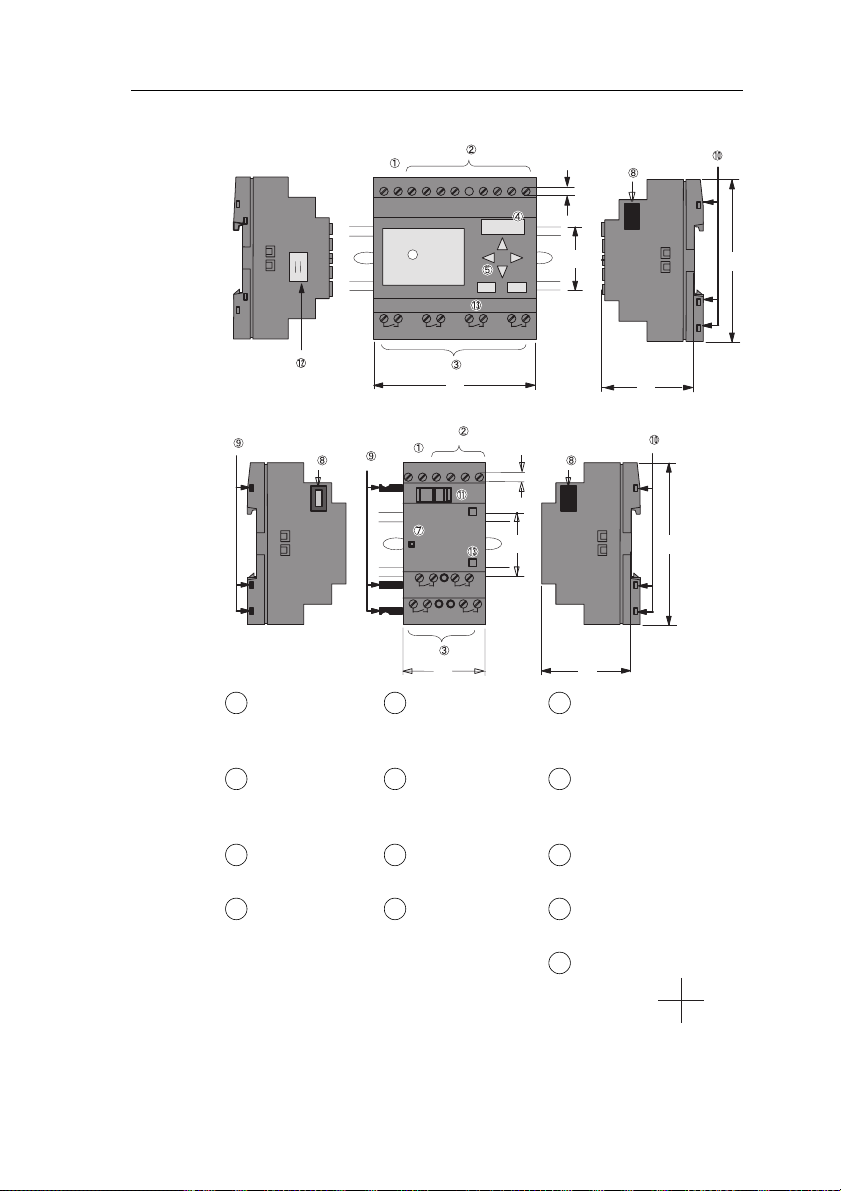
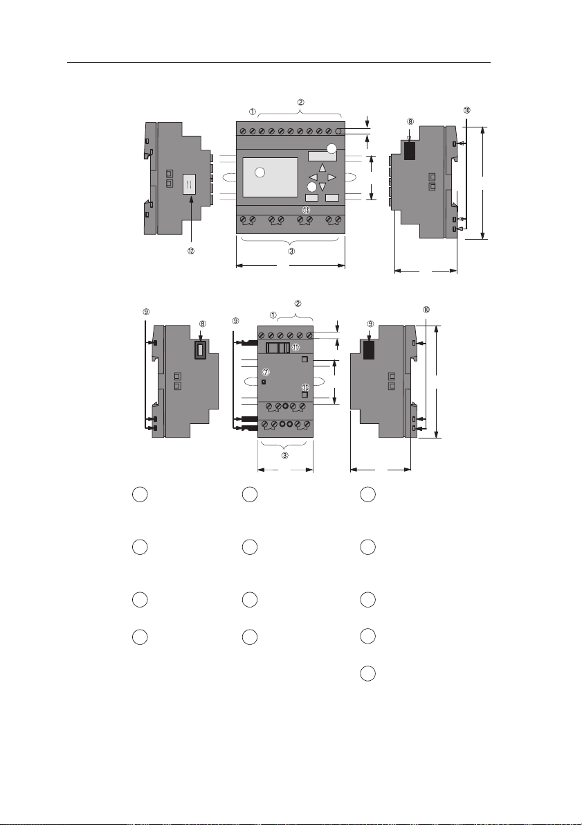
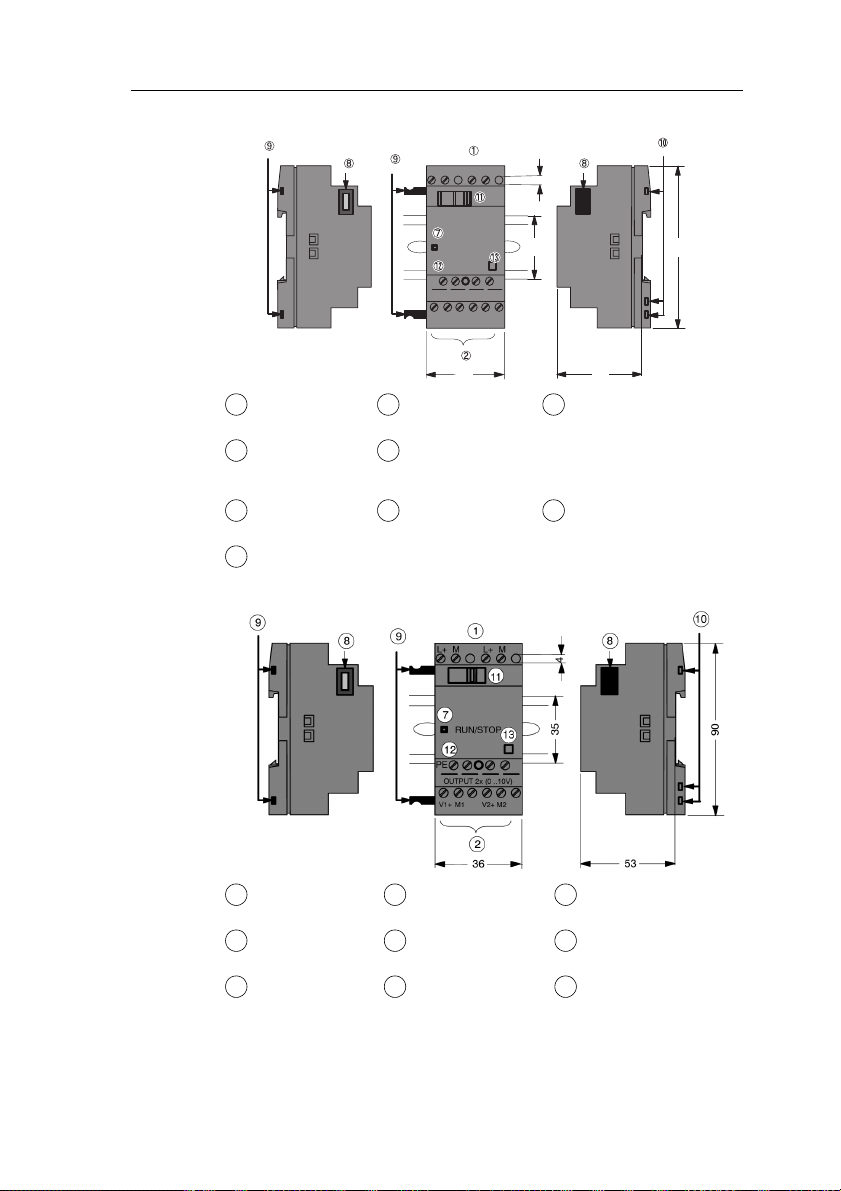
The IDEC SmartRelay installation dimensions are compliant
with DIN 43880.
IDEC SmartRelay can be snap–mounted to 35 mm DIN rails
to EN 50022 or on the wall.
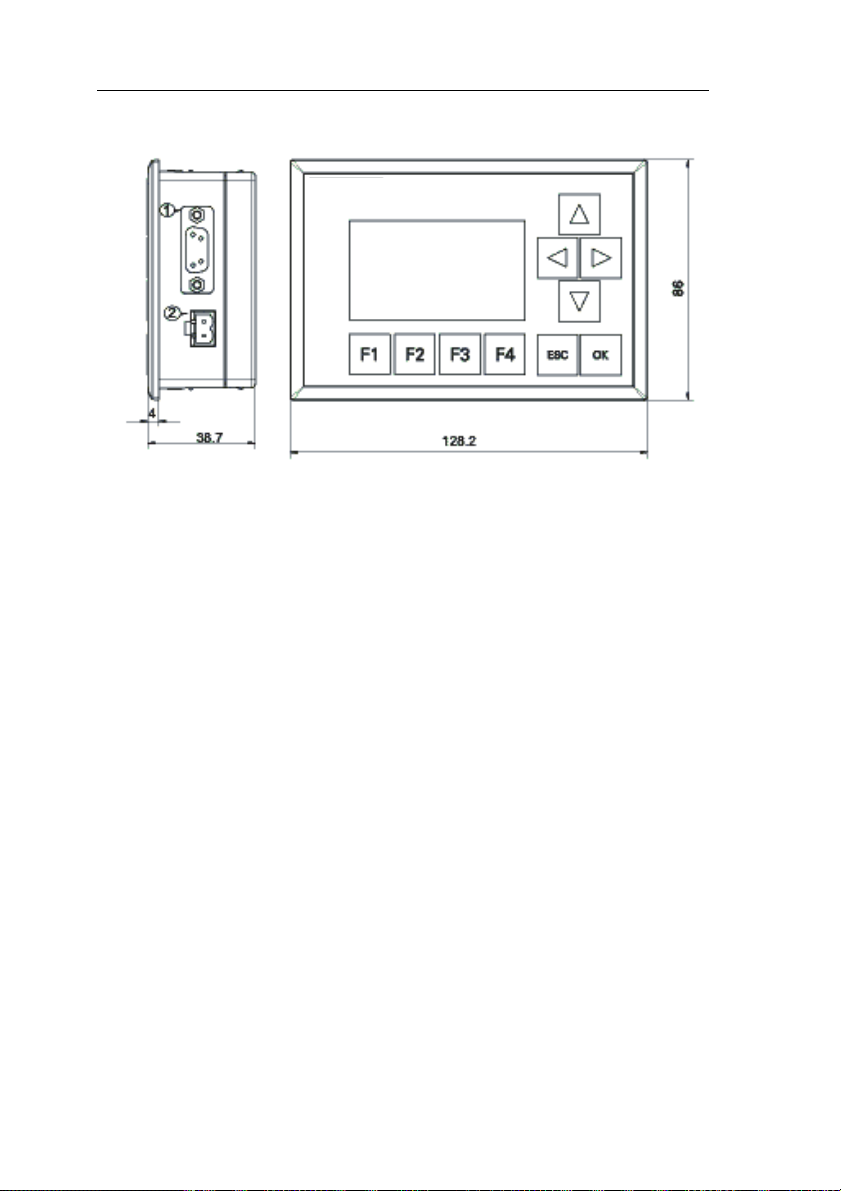
IDEC SmartRelay width:
• Text Display has a width of 128.2 mm, which corresponds
to 8 subunits
• IDEC SmartRelay base modules have a width of 72 mm,
which corresponds to 4 subunits
• IDEC SmartRelay expansion modules have a width of
36 mm, which corresponds to 2 or 4 subunits
Note
The figure below shows you an example of the installation and
removal of a FL1E-H12RCC and a digital module. The measures
shown apply to all other IDEC SmartRelay Base versions and
expansion modules
Warning
!
Always switch off power before you “remove” and “insert” an
expansion module.
22 IDEC SmartRelay Manual
Page 37

IDEC SmartRelay installation and wiring
2.2.1 DIN rail mounting
Mounting
How to mount an IDEC SmartRelay base module and a
digital module onto a DIN rail:
IDEC SmartRelay base module:
1. Hook the IDEC SmartRelay base module onto the rail.
2. Push down the lower end to snap it on. The mounting
interlock at the rear must engage.
1
6
3
5
2
IDEC SmartRelay digital module:
3. On the right side of the IDEC SmartRelay base module/
IDEC SmartRelay expansion module, remove the
connector cap.
4. Place the digital module onto the DIN rail on the righthand side of the IDEC SmartRelay base module.
5. Slide the digital module towards the left until it contacts
the IDEC SmartRelay base module.
4
IDEC SmartRelay Manual 23
Page 38

IDEC SmartRelay installation and wiring
6. Using a screwdriver, push the interlock to the left. In its
end position the slide interlock engages in IDEC
SmartRelay base module.
Repeat steps 3 through 6 to mount further expansion
modules.
Note
The expansion interface on the last expansion module must be
covered.
24 IDEC SmartRelay Manual
Page 39

Removal
IDEC SmartRelay installation and wiring
To remove IDEC SmartRelay:
....... if you have installed only one IDEC SmartRelay base
module:
Part
A
1. Insert a screwdriver into the eyelet at the bottom of the
slide interlock and move the latch downward.
2. Swing the IDEC SmartRelay base module off the DIN rail.
1
2
2
1
4
3
AB
....... if you have connected at least one expansion
module to IDEC SmartRelay base module:
B
Part
1. Using a screwdriver, push the integrate slide interlock to
the right.
2. Slide the expansion module off towards the right.
3. Insert a screwdriver into the eyelet at the bottom of the
slide interlock and lever it downward.
4. Swing the expansion module off the profile rail.
Repeat steps 1 to 4 for all other expansion modules.
Note
If you have connected more than one expansion module, it is
advisable to start removal with the last module at the right-hand
side.
Make sure the slide interlock of the module to be installed/removed
is not engaged in the next module.
IDEC SmartRelay Manual 25
Page 40

IDEC SmartRelay installation and wiring
2.2.2 Wall-mounting
For wall-mounting, first slide the mounting slides on the rear
side of the devices towards the outside. You can now wallmount IDEC SmartRelay by means of two mounting slides
and two
Drilling template for wall-mounting
Before you can wall-mount IDEC SmartRelay, you need to
drill holes using the template shown below.
φ
M4 screws (tightening torque 0.8 to 1.2 Nm).
Mounting slides
+0.2
53.5–0.0
+0.2
35.5–0.0
98 +/– 0.3
1
2
2 2
+0.2
n x 35.5–0.0
All dimensions in mm
Bore hole for
φ
M4 screw, tightening torque 0.8 to 1.2 Nm
1) IDEC SmartRelay base module
2) IDEC SmartRelay expansion modules
26 IDEC SmartRelay Manual
Page 41

IDEC SmartRelay installation and wiring
2.2.3 Mounting the Text Display
To prepare the mounting surface for the optional Text
Display and mount it, follow these steps:
1. Cut a 119.5 mm x 78.5 mm hole in the mounting surface.
119.5+0.5mm
78.5+0.5mm
2. Place the included gasket on the frontplate of the Text
Display.
3. Fit the Text Display into the cutout you made in the
mounting surface.
4. Attach the mounting brackets (included) to the Text
Display.
5. Tighten the mounting screws on the mounting brackets to
0.15...0.2 Nm torque to secure the Text Display.
➀
Mounting brackets
➁ Mounting screws
➂ Gasket
You can then use the included cable to connect the Text
Display to the IDEC SmartRelay base module up to a
distance of 2.5 meters. You can extend this distance to up to
ten meters by using a standard Sub-D cable together with
the Text Display cable.
IDEC SmartRelay Manual 27
Page 42

IDEC SmartRelay installation and wiring
2.3 Wiring IDEC SmartRelay
Wire IDEC SmartRelay using a screwdriver with a 3-mm
blade.
You do not need wire ferrules for the terminals. You can use
conductors with cross-sections of up to the following
thicknesses:
• 1 x 2.5 mm
• 2 x 1.5 mm2 for each second terminal chamber
Tightening torque: 0.4...0.5 Nm or 3...4 in-lbs.
Recommended ferrules
Ferrules order No.
For 1-cable connection
Cross-section
2
[mm
0.3 22 AI0,5-10WH
0.5 20 AI0,5-10WH
0.75 18 AI0,75-8GY
1.25 18 AI1,5-8BK
2.0 16 AI2,5-8BU BT2-9-1 −
Recommended
crimping tool
AWG
]
For 2-cable connection
Cross-section
2
[mm
0.3 22 AI-TWIN2X0,5-8WH
0.5 20 AI-TWIN2X0,5-8WH
0.75 18 AI-TWIN2X0,75-8GY
1.25 18 AI-TWIN2X1,5-8BK
Recommended
crimping tool
AWG
]
2
Phoenix Contact
Ferrule type No.
CRIMPFOX ZA 3
Phoenix Contact
Ferrule type No.
CRIMPFOX ZA 3
NIC HIFU
Blade Terminals
type No.
BT1.25-10-1
BT1.25-10-1
BT2-9-1
NH1
NH61
NIC HIFU
Insulated Pin Terminals
type No.
−
TGN-TC-1.25-11T
NH11
NH32
NH65
Note
Always cover the terminals after you have completed the
installation. To protect IDEC SmartRelay adequately from
impermissible contact to live parts, comply with local standards.
28 IDEC SmartRelay Manual
Page 43

IDEC SmartRelay installation and wiring
2.3.1 Connecting the power supply
IDEC SmartRelays (FL1E-*12RCC, FL1B-M08C2R2) are
suitable for nominal line voltages of 100 V AC/DC and 240 V
AC/DC. IDEC SmartRelays (FL1E-*12RCA, FL1BM08D2R2) are suitable for a supply voltage of 24 V AC/DC.
IDEC SmartRelays (FL1E-H12SND, FL1B-M08B1S2) are
suitable for a supply voltage of 24 V DC. IDEC SmartRelays
(FL1E-*12RCE, FL1B-M08B2R2) are suitable for a supply
voltage of 12 V AC/DC or 24 V AC/DC.
Note the information on connection in the product
information document shipped with your device and the
technical specifications in Appendix A relating to permissible
voltage tolerances, line frequency and current consumption.
The Text Display must be supplied with a voltage of 12 V DC
or 24 V AC/DC.
Note
A power failure might cause an additional edge triggering signal at
the special functions.
The stored data will be from the last uninterrupted cycle.
Connecting IDEC SmartRelay
To connect IDEC SmartRelay to the power supply:
IDEC SmartRelay .....
with DC power supply
L+
M
IDEC SmartRelay .....
with AC power supply
L1
N
ML+ I1 I2 I3 I4 I5
Protection with safety fuse if
required (recommended) for:
FL1E-H12RCE: 0.8 A
FL1E-H12SND: 2.0 A
IDEC SmartRelay Manual 29
To suppress surge voltages,
install varistors (MOV) with an
operating voltage at least 20 %
above the rated voltage.
I1 I2 I3 I4L1 N
Page 44

IDEC SmartRelay installation and wiring
Note
IDEC SmartRelay is a double-insulated switchgear. You do not
need to connect an equipment grounding conductor.
Circuit protection with AC voltage
To suppress voltage peaks on the power supply lines, you
can install a metal oxide varistor (MOV). Make sure the
operating voltage of the varistor (MOV) used lies at least
20 % above the rated voltage.
2.3.2 Connecting the Text Display power supply
The Text Display must be connected to an external power
supply that supplies a voltage of 12 V DC or 24 V AC/DC. A
power connector is included with the Text Display.
1 2
(2)(1)
c Power supply
d Communication interface
The power connection is non-polar; the ground can be
connected on either the left or right side.
Note
IDEC recommends that you protect the Text Display with a 0.5 A
safety fuse on the power supply.
30 IDEC SmartRelay Manual
Page 45

IDEC SmartRelay installation and wiring
2.3.3 Connecting IDEC SmartRelay inputs
Requirements
At the inputs you connect sensor elements such as:
momentary switches, switches, light barriers, daylight
control switches etc.
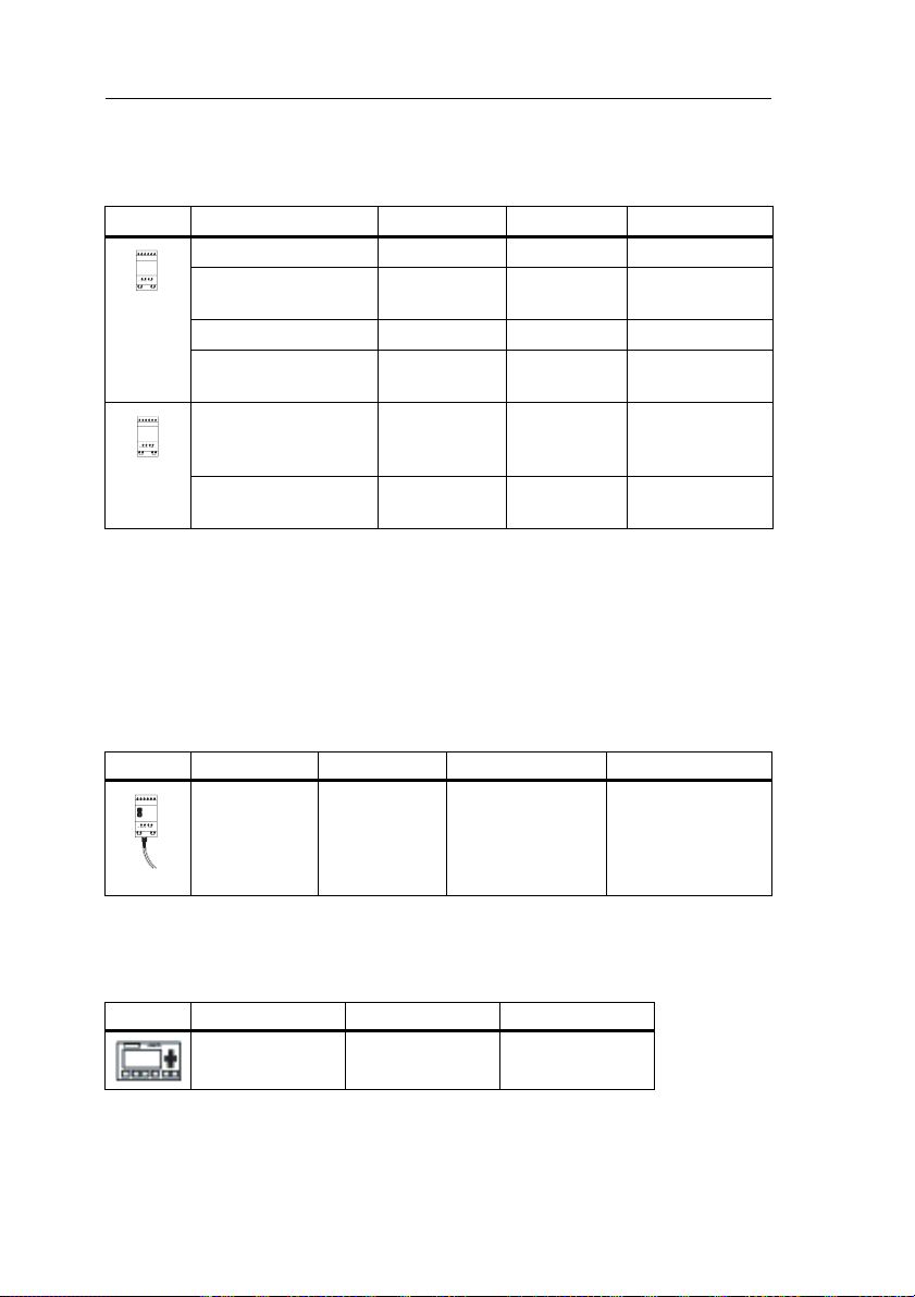
Sensor characteristics for IDEC SmartRelay
FL1E-H12RCE/
FL1E-B12RCE
I3 ... I6 I1,I2,I7,I8 I3 ... I6 I1,I2,I7,I8 I1 ... I8 I1 ... I8
Signal status 0 < 5 V DC < 5 V DC < 5 V DC < 5 V DC < 5 V DC < 5 V DC
Input current
Signal status 1
Input current
Signal status 0
Input current
Signal status 1
Input current
(1): 1.0 mA (Version 1 to 5 specifications)
(2): 8 V DC (Version 1 to 5 specifications)
(3): 1.0 mA (Version 1 to 4 specifications)
(4): 8 V DC (Version 1 to 4 specifications)
(5): 1.5 mA (Version 1 to 4 specifications)
< 0.85 mA < 0.05 mA < 0.85 mA < 0.05 mA
> 8.5 V DC > 8.5 V DC > 12 V DC > 12 V DC
> 1.5 mA > 0.1 mA > 2 mA > 0.15 mA > 1.5 mA > 2 mA
FL1E-H12RCA/
FL1E-B12RCA
FL1B-
M08D2R2 (AC)
< 5 V AC
< 1.0 mA
> 12 V AC
> 2.5 mA
FL1E-H12RCA/
FL1E-B12RCA
M08D2R2 (DC)
FL1E-H12SND FL1B-
FL1E-H12RCC/
FL1E-B12RCC
FL1B-
< 5 V DC
< 1.0 mA
> 12 V DC
> 2.5 mA
FL1B-
M08C2R2 (AC)
< 40 V AC
< 0.03 mA
> 79 V AC
> 0.08 mA
M08B2R2
< 0.85 mA
> 8.5 V DC
FL1E-H12RCC/
FL1E-B12RCC
M08C2R2 (AC)
FL1B-
M08B1S2
(1)
< 0.85 mA
(2)
> 12 V DC
FL1B-
< 30 V DC
< 0.03 mA
> 79 V DC
> 0.08 mA
(5)
Note
The digital inputs of FL1E-H12RCC/FL1E-B12RCC are divided into
two groups, each consisting of four inputs. Within the same group,
all inputs must be operated on the same phase. Different phases
are only possible between the groups.
Example: I1 to I4 on phase L1, I5 to I8 on phase L2.
Inputs within the FL1B-M08C2R2 may not be connected to
different phases.
(3)
(4)
IDEC SmartRelay Manual 31
Page 46

IDEC SmartRelay installation and wiring
Sensor connections
Connecting glow lamps and 2-wire proximity switches
(Bero) to FL1E-H12RCC/FL1E-B12RCC or FL1BM08C2R2 (AC)
The figure below shows how you connect a switch with a
glow lamp to IDEC SmartRelay. The current that flows
through the glow lamp allows IDEC SmartRelay to detect a
“1” signal even though the switch contact is not closed. If,
however, you use a switch the glow lamp of which is fitted
with a power supply, this response does not occur.
L1
N
C
NL1
X-capacitor 2.5 kV, 100 nF
Take into account the quiescent current of any 2-wire
proximity switches used. The level of the quiescent current
of some 2-wire proximity switches is high enough to trigger a
logical ”1” signal at the IDEC SmartRelay input. You should
therefore compare the quiescent current of the proximity
switches with the technical data of inputs in Appendix A.
Remedy
To suppress this response, use an X capacitor rated at
100 nF and 2.5 kV. In a destructive situation, this type of
capacitor safely disconnects. You must choose the voltage
level for which the capacitor is rated such that it is not
destroyed in the case of overvoltage!
At 230 V AC, the voltage between N and an input I(n) must
not be greater than 40 V to guarantee a ”0” signal. You can
connect approximately ten glow lamps to the capacitor.
Restrictions
Signal status transitions 0 → 1 / 1 → 0:
After a 0 to 1 or 1 to 0 transition, the signal must remain
constant at the input at least for the duration of one program
cycle, so that IDEC SmartRelay can detect the new signal
status.
The program execution time is determined by the size of the
circuit program. Appendix B contains a benchmark test
routine that you can use to determine the current scan cycle
time.
32 IDEC SmartRelay Manual
Page 47

IDEC SmartRelay installation and wiring
Special features of FL1E-H12RCE/FL1E-B12RCE and FL1E-H12SND
Fast inputs: I3, I4, I5 and I6:
These versions are also equipped with fast inputs (up/down
counters, frequency triggers). The restrictions mentioned
earlier do not apply to these fast inputs.
Note
The fast inputs I3, I4, I5 and I6 are the same as in the previous
versions FL1A to FL1D; therefore, a circuit program that is written
in these versions can be transferred to the new FL1E devices with
the programming software WindLGC, without any changes to these
features. The fast inputs have increased from 2 kHz to 5 kHz with
the FL1E series.
Expansion modules do not have fast inputs.
Analog inputs: I1 and I2, I7 and I8:
The inputs I1, I2, I7 and I8 of IDEC SmartRelay versions
FL1E-H12RCE/FL1E-B12RCE and FL1E-H12SND can be
used as either digital inputs or analog inputs. The input mode
is defined in the IDEC SmartRelay circuit program.
The inputs I1, I2, I7 and I8 provide digital inputs, and the
inputs AI3, AI4, AI1 and AI2 provide analog inputs, as
described in Chapter 4.1. AI3 corresponds to the input
terminal I1; AI4 corresponds to I2; AI1 corresponds to I7; AI2
corresponds to I8. The use of AI3 and AI4 is optional. You
configure your IDEC SmartRelay to use either two or four
analog inputs as described in section 5.2.4.
When using inputs I1, I2, I7 and I8 as analog inputs, only the
range from 0 to 10 V DC is available.
Connecting a potentiometer to inputs I1, I2, I7 and I8
To allow you to achieve 10 V as the maximum value when
you completely turn the potentiometer once, you must
connect a series resistor on the potentiometer’s input side
regardless of the input voltage (see figure below).
We suggest the following sizes of potentiometers and
associated series resistors:
Voltage Potentiometer Series Resistor
12 V 5
24 V 5
IDEC SmartRelay Manual 33
kΩ -
kΩ 6.6 kΩ
Page 48

IDEC SmartRelay installation and wiring
When using a potentiometer and 10 V input voltage as the
maximum value, you must ensure that with a connected
input voltage of 24 V, 14 V must release via the series
resistor so that a maximum of 10 V are supplied when you
turn the potentiometer one full rotation. With a voltage of
12 V, this can be neglected.
Note
The FL1B-J2B2 expansion module provides additional analog
inputs.
Always use twisted and shielded cables for analog signals, and
keep these as short as possible.
Sensor connections
To connect sensors to IDEC SmartRelay :
FL1E-H12RCA / FL1E-B12RCA / FL1E-H12RCE / FL1E-B12RCE /
FL1E-H12SND
L+
M
ML+ I1 I2 I3 I4 I5 I8
*)
The inputs of these devices are not
isolated and therefore require a
common reference potential (chassis
ground ).
With FL1E-H12RCE / FL1E-B12RCE
and FL1E-H12SND modules, you can
tap analog signals between the
supply voltage and chassis ground
(* = series resistor with 24 V DC).
On the FL1E-H12RCA/-B12RCA, P1 and P2
are indicated in place of L+ and M, respectively
.
FL1E-H12RCC / FL1E-B12RCC
L3
L2
L1
N
NL1 I1 I2 I3 I4 I5 I6
Warning
!
Current safety regulations (VDE 0110, ... and IEC 61131-2, ... as
well as cULus) do not permit the connection of different phases to
an AC input group (I1 to I4 or I5 to I8) or to the inputs of a digital
module.
34 IDEC SmartRelay Manual
The inputs of these devices are
arranged in 2 groups, each
consisting of 4 inputs. Different
phases are only possible between
blocks, but not within the blocks.
Page 49

FL1B-J2B2
IDEC SmartRelay installation and wiring
L+
M
ML+
ML+
RUN/STOP
PE
PE
PE terminal for
connecting earth and
shielding the analog
measuring cable
c Earth
d Cable shielding
e DIN rail
L+M
Current
Reference
0...20mA
Current
Current measurement
M
U1 I2 M2 U2I1 M1
0-10V
Voltage measurement
The illustration above shows an example of four–wire
current measurement and two–wire voltage measurement.
Connecting a two–wire sensor to the FL1B-J2B2
Wire up the two–wire sensor’s connecting wires as follows:
1. Connect the sensor’s output to connection U (0 ... 10 V
voltage measurement) or to connection I (0 ... 20 mA
current measurement) of the AM 2 module.
2. Connect the plus connector on the sensor to the 24 V
supply voltage (L+).
3. Connect the ground connection on the sensor to the
corresponding M input (M1 or M2) on the AM 2 module.
IDEC SmartRelay Manual 35
Page 50

IDEC SmartRelay installation and wiring
Input Internal Circuit
FL1E-H12RCC / FL1E-B12RCC
Digital AC/DC Input
390kΩ 180kΩ 270kΩ
I1~I8
Internal Circuit
100nF
N
FL1B-M08C2R2
Digital AC/DC Input
390kΩ 390kΩ
I1~I8
100nF
N
When using the AC two-wire sensor
AC
2-wire
Sensor
R4
47kΩ
270kΩ
Internal Circuit
62kΩ
I1 to I8
N
100 to 240 V AC
L1
36 IDEC SmartRelay Manual
Page 51

IDEC SmartRelay installation and wiring
t
t
FL1E-H12RCA / FL1E-B12RCA
Digital AC/DC Input
I1~I8
P2
4.3kΩ
100nF
510Ω
FL1B-M08D2R2
Digital AC/DC Input
I1~I8
P2
4.3kΩ
510Ω100nF
When using the AC two-wire sensor
AC
2-wire
Sensor
R3
I1 to I8
+5V
+5V
Internal Circui
150kΩ
Internal
Circuit
100nF
Internal Circui
Internal
Circuit
100nF
P1
240 V AC
P2
IDEC SmartRelay Manual 37
Page 52

IDEC SmartRelay installation and wiring
FL1E-H12RCE / FL1E-B12RCE / FL1E-H12SND
Digital DC Input
3.6kΩ 270kΩ
I1~I8
2.21kΩ47nF
M
FL1B-M08B2R2/FL1B-M08B1S2
Digital DC Input
3.6kΩ
I1~I8
2.2kΩ100nF
M
270kΩ
FL1E-H12RCE / FL1E-B12RCE / FL1E-H12SND
Analog Input (0-10V)
54kΩ
I1, I2, I7, I8
Internal Circuit
Internal Circuit
Internal Circuit
10nF
M
18kΩ
+5V
FL1B-J2B2
Analog Input (0-10V)
38kΩ
U1, U2
10nF
M1, M2
38 IDEC SmartRelay Manual
38kΩ
+5V
Internal Circuit
Page 53

FL1B-J2B2
Analog Input (0-20mA)
Note
Fluctuating analog values are due to screening on the connecting
wire from the analog valuator device to the analog FL1B-J2B2
expansion module (encoder wire) that has either been mounted
incorrectly or not at all.
To avoid fluctuating analog values when using these expansion
modules, proceed as follows:
• Use only shielded encoder wires.
• Shorten the encoder wire as much as possible. The encoder
wire must not be more than 10 meters long.
• Clamp the encoder wire on one side only and clamp it only to
the PE terminal on the FL1B-J2B2 / FL1D-K2B2 expansion
module.
• Connect ground on the encoder supply to the PE terminal on the
expansion module.
IDEC SmartRelay installation and wiring
Internal
Circuit
IDEC SmartRelay Manual 39
Page 54

IDEC SmartRelay installation and wiring
2.3.4 Connecting outputs
FL1E-H12RCA / FL1E-B12RCA / FL1E-H12RCC / FL1E-B12RCC /
FL1E-H12RCE / FL1E-B12RCE
The FL1E-H12RCA / FL1E-B12RCA / FL1E-H12RCC /
FL1E-B12RCC / FL1E-H12RCE / FL1E-B12RCE version is
equipped with relay outputs. The potential of the relay
contacts is isolated from the power supply and the inputs.
Requirements for relay outputs
You can connect various loads to the outputs, e.g. lamps,
fluorescent lamps, motors, contactor relays etc. For
information on the properties required for the loads
connected to FL1E-H12RCA / FL1E-B12RCA / FL1EH12RCC / FL1E-B12RCC / FL1E-H12RCE / FL1E-B12RCE,
refer to Appendix A.
Connecting
This is how you connect the load to FL1E-H12RCA / FL1EB12RCA / FL1E-H12RCC / FL1E-B12RCC / FL1E-H12RCE
/ FL1E-B12RCE:
FL1B-M08
1 2
1 2
Q5 Q6
1 2
1 2
Q2
Q1
Load Load
Protection with automatic circuit-breaker, max. 16 A, characteristics
B16, e.g.: Power circuit-breaker 5SX2 116-6 (if required)
IDEC SmartRelay with transistor outputs
IDEC SmartRelay versions with transistor outputs can be
identified by the fact that the letter R is missing from their
type name. The outputs are short circuit-proof and overloadproof. An auxiliary load voltage supply is not necessary,
because IDEC SmartRelay supplies the load voltage.
40 IDEC SmartRelay Manual
Page 55

IDEC SmartRelay installation and wiring
Requirements for transistor outputs
The load connected to IDEC SmartRelay must have the
following characteristics:
• The maximum switched current is 0.3 A per output.
Connecting
This is how you connect the load to an IDEC SmartRelay
with transistor outputs:
Q5 Q6MM
Q1Q2M
M
Load Load
Load: 24 V DC, 0.3 A max.
FL1D-K2B2
L
+
M
FL1B-M08
1 Earth
2 DIN rail
1
2
L+ M
RUN/STOP
PE
OUTPUT 2x(0..10V)
M1
V1+
L+ M
V2+
M2
V1, V2: 0 - 10 V DC
0 10V0 10V
RR
R: min. 5 k
Ω
IDEC SmartRelay Manual 41
Page 56

IDEC SmartRelay installation and wiring
Output Internal Circuit
FL1E-H12RCA / FL1E-B12RCA / FL1E-H12RCC / FL1E-B12RCC /
FL1E-H12RCE / FL1E-B12RCE / FL1B-M08B2R2 / FL1B-M08C2R2 /
FL1B-M08D2R2
Relay Output
Internal Circuit
+24V
2
Internal
Circuit
47kΩ
27kΩ
FL1E-H12SND / FL1B-M08B1S2
Transister Output (Source)
+24V
Internal
Circuit
10kΩ10nF 10nF
FL1D-K2B2
Analog Output (0-10V)
Internal
Circuit
+
-
4.7kΩ
Internal Circuit
+24V Internal Circuit
10Ω
1
100nF
Q1~Q4
Q1~Q4
M
(
V1+, V2+
(
M1, M2
)
)
42 IDEC SmartRelay Manual
Page 57

IDEC SmartRelay installation and wiring
2.3.5 Connecting the AS interface bus
To set the address of the module on the AS interface bus,
you need an addressing unit.
Valid addresses are in the range of 1 to 31. Use each
address once only.
You can set the address on the AS interface bus before or
after installation.
If the installed module is addressed via the address socket,
the AS-Interface voltage must be disconnected beforehand.
This is necessary for safety reasons.
RUN/STOP
AS-I
AS-I
ADDR
+–
+–
Networking on the AS interface bus
To make the connection to the AS interface bus, you need a
communications-capable IDEC SmartRelay variant:
• IDEC SmartRelay base module + CM AS-I.
To be able to send data across the AS interface bus to IDEC
SmartRelay and to receive data from it in the same way, you
also need:
• an AS interface power supply and
• an AS interface master.
IDEC SmartRelay can only be accepted as a slave on the AS
interface bus. This means that it is not possible to directly
exchange data between two IDEC SmartRelay devices.
Data is always exchanged across the AS interface master.
IDEC SmartRelay Manual 43
Page 58

IDEC SmartRelay installation and wiring
Warning
!
The AS-Interface and IDEC SmartRelay systems must never be
connected together electrically!
Use safe isolation acc. to IEC 61131-2, EN 50178, UL 508, CSA
C22.2 No. 42.
Logic Assignments
IDEC SmartRelay sys-
tem
Inputs Output data bits
I
n
I
n+1
I
n+2
I
n+3
Outputs Output data bits
Q
n
Q
n+1
Q
n+2
Q
n+3
AS Interface system
D0
D1
D2
D3
D0
D1
D2
D3
”n” depends on the plug–in position of the expansion module
relative to the IDEC SmartRelay base module. It indicates
the number of the input or output in IDEC SmartRelay
program code.
Note
Ensure that there is enough space for the inputs/outputs of the AS
interface in the IDEC SmartRelay’s address space. If you are
already using more than 12 physical outputs or more than 20
physical inputs, it is no longer possible to operate the CM AS
interface!
44 IDEC SmartRelay Manual
Page 59

IDEC SmartRelay installation and wiring
2.4 Putting into operation
2.4.1 Switching on the IDEC SmartRelay/Power On
IDEC SmartRelay does not have a power switch. The
reaction of IDEC SmartRelay during startup depends on the
following:
• Whether a circuit program is stored in IDEC SmartRelay
• Whether a memory cartridge or combined memory/
battery cartridge is inserted
• Whether this is an IDEC SmartRelay version without
display unit (FL1E-B12...)
• The status of IDEC SmartRelay at the time of power
failure.
All possible reactions of IDEC SmartRelay are described on
the following page.
To ensure that the expansion module on IDEC SmartRelay
changes to RUN mode, check the following:
• Has the sliding contact between IDEC SmartRelay and
the expansion module snapped into place properly?
• Is the power supply connected to the expansion module?
• In addition, always ensure that you switch on the power
supply to the expansion module first before activating the
power supply to the IDEC SmartRelay base module (or
activate both power supplies at the same time); if you do
not do this, the system does not detect the expansion
module when you start up the IDEC SmartRelay base
module.
Note
After power-up, the FL1E performs initialization. After completing
initialization, the FL1E is ready to start to run. During initialization,
a sandglass is displayed on the CPU module with display, or the
LED is lit red on the CPU module without display.
Initialization time (regardless of expansion module)
When a memory cartridge or a combined memory/battery cartridge
is installed: Max. 10 sec
When a cartridge is not installed or when a battery cartridge is
installed: Max. 9 sec
*The initialization time depends on the program size.
IDEC SmartRelay Manual 45
Page 60

IDEC SmartRelay installation and wiring
Notes for Using Expansion I/O Modules of Version 7 or earlier
When using 3 or more expansion I/O modules including
those of the versions listed below, immediately after powerup, it takes a specific period of time for the base module to
accept input signals from the expansion I/O modules. Until
the output terminals on the expansion I/O module are actually turned on or off.
Expansion I/O Modules
FL1B-M08C2R2(Version 1 to 7),
FL1B-M08B1S2(Version 1 to 7),
FL1B-M08B2R2(Version 1 to 7),
FL1B-M08D2R2(Version 1 to 7),
FL1B-J2B2(Version 1 to 7),
FL1D-K2B2(Version 1)
For identifying the version, see page 4.
Power supply
External input signal to base module and expansion modules
Version 7 or earlier *2
Version 8 or later
10sec
The initialization period
of base module
During the initialization of expansion modules
FB process
I/O signal of base module is reflected
in the user program.
I/O signal of expansion modules is reflected
in the user program. *1
*1
I/O signal of expansion modules
is reflected.
*1 Output signal of base module and expansion modules
are reflected 1 scan time after each input signal has been reflected.
*2 During the initialization period of expansion I/O modules,
inputs and outputs are off. In addition, the length of initialization period varies with expansion I/O modules , and I/O response depends on the expansion I/O modules.
For further information, see our Internet address
(URL: http://www.idec.com/faq/en/controller/).
46 IDEC SmartRelay Manual
Page 61

IDEC SmartRelay installation and wiring
Before power off After power on
No Program
Press ESC
No program in
memory
Mo 09:00
2003-01-27
I:
0.. 123456789
1..0123456789
2..01234
Q:
0..123456789
1..0123456
IDEC SmartRelay
in RUN mode
Program in
memory
You can also memorize four simple rules for starting IDEC
SmartRelay :
1. If neither IDEC SmartRelay nor the inserted memory
2. A circuit program on the memory cartridge or combined
3. If there is a circuit program in IDEC SmartRelay or on the
No program
Press ESC
>Program..
Card..
Setup..
Start
Mo 09:00
2002-01-31
I:
0.. 123456789
1..0123456789
2..01234
IDEC SmartRelay in
RUN mode
Mo 09:00
2008-05-05
I:
0.. 123456789
1..0123456789
2..01234
>Program..
Card..
Setup..
Start
>Program..
Card..
Setup..
Start
with stored program from
IDEC SmartRelay
with a program copied from
the memory cartridge or
combined memory/battery
cartridge in IDEC
SmartRelay
with stored program from
IDEC SmartRelay
with program copied from
the memory cartridge or
combined memory/battery
cartridge in IDEC
SmartRelay
B3:
Par = 0300
Cnt = 0028
B1
&
Q1
or
(empty)
(with program)
or
(empty)
(with program)
or
(empty)
(with program)
cartridge or combined memory/battery cartridge contains
a circuit program, IDEC SmartRelay (with display unit)
reports: ’No Program / Press ESC’.
memory/battery cartridge is automatically copied to IDEC
SmartRelay. The circuit program in IDEC SmartRelay is
overwritten.
memory cartridge or combined memory/battery cartridge,
IDEC SmartRelay adopts the operational state it had prior
to POWER-OFF. Versions without display unit (FL1EB12...) automatically change from STOP to RUN (LED
changes from red to green).
IDEC SmartRelay Manual 47
Page 62

IDEC SmartRelay installation and wiring
4. If you have enabled retentivity for at least one function, or
a function is permanently retentive, the current values are
retained at POWER-OFF.
Note
When a power failure occurs while you are entering a circuit
program, the program in IDEC SmartRelay will be deleted after
power is returned.
Before you modify the circuit program, save a backup copy of your
original to a memory cartridge, a combined memory/battery
cartridge or to a computer (WindLGC).
2.4.2 Operating states
IDEC SmartRelay base module operating states
IDEC SmartRelay base module/Pure knows has two
operating states: STOP and RUN.
STOP RUN
• The display shows: ’No Program’
(not FL1E-B12...)
• Switching IDEC SmartRelay to
programming mode
(not FL1E-B12...)
•LED is red
(only FL1E-B12...)
Action of IDEC SmartRelay:
• The input data is not read.
• The circuit program is not
executed.
• The relay contacts are
permanently open or the
transistor outputs are switched
off.
• Display: Screen mask for
monitoring I/Os and messages
(after START in the main menu)
(not FL1E-B12...)
• Switching IDEC SmartRelay to
parameter assignment mode
(not FL1E-B12...)
• LED is green
(only FL1E-B12...)
Action of IDEC SmartRelay:
• IDEC SmartRelay reads the
status of the inputs.
• IDEC SmartRelay uses the circuit
program to calculate the status of
the outputs.
• IDEC SmartRelay switches the
relay/transistor outputs on or off.
Note
After switching the power on, the system briefly switches through
the outputs on the FL1E-H12SND. With an open circuit, a voltage
of > 8 V can occur for up to approximately 100 ms; when loaded,
this time reduces to a matter of microseconds.
48 IDEC SmartRelay Manual
Page 63

IDEC SmartRelay installation and wiring
IDEC SmartRelay expansion modules, operating states
IDEC SmartRelay expansion modules have three operating
states: The LED (RUN/STOP) is lit green, red or orange.
LED (RUN/STOP) is lit
Green (RUN) Red (STOP) Orange/Yellow
The expansion module
communicates with the
device to the left.
The expansion module
does not communicate
with the device to its
left.
Initialization phase of
the expansion module
CM AS Interface, communication states
The CM AS Interface has three communication states: The
LED is lit green, red or flashes red/yellow.
LED AS-I is lit
Green Red Red/Yellow
AS Interface
communication OK
AS Interface
communication failed
Slave has address ”0”.
CM AS Interface, behavior on communication failure
• If the AS Interface voltage fails, communication between
the IDEC SmartRelay system and the expansion
modules, which are arranged to the right of the IDEC
SmartRelay CM AS Interface expansion module, is
interrupted.
Recommendation: Position IDEC SmartRelay CM AS
Interface on the far right side.
• If communication is interrupted, the switching outputs are
reset after about 40 to 100 ms.
IDEC SmartRelay Manual 49
Page 64

IDEC SmartRelay installation and wiring
50 IDEC SmartRelay Manual
Page 65

Programming IDEC SmartRelay
Getting started with IDEC SmartRelay
Programming refers to creating a circuit program from the
IDEC SmartRelay base module.
In this chapter you will learn how to use IDEC SmartRelay to
create the IDEC SmartRelay circuit programs for your
application.
WindLGC is the IDEC SmartRelay programming software
that you can use on your PC to quickly and easily create,
test, modify save and print the circuit programs. The topics
in this manual, however, relate only to the creation of circuit
programs on the actual IDEC SmartRelay base module. The
programming software WindLGC contains extensive online
help. See also Chapter 7 for additional information.
Note
IDEC SmartRelay versions without a display unit; that is, the FL1EB12RCE, FL1E-B12RCA and FL1E-B12RCC versions, do not have
an operator panel and display unit. They are primarily designed for
use in small machine and process equipment engineering systems
for series production.
FL1E-B12... versions are not programmed directly on the device.
Instead, the circuit program is downloaded to the device from
WindLGC or from memory cartridges or combined memory/battery
cartridges from other IDEC SmartRelay devices.
IDEC SmartRelay versions without a display cannot write data to
memory cartridges or combined memory/battery cartridges.
See Chapters 6, 7 and Appendix C.
3
A small example in the first part of this chapter introduces the
operating principles of IDEC SmartRelay:
• You will learn the meaning of two basic terms, namely the
connector and the block.
• As the next step, you will create a circuit program based
on a simple conventional circuit.
• Lastly, you will enter this program directly in IDEC
SmartRelay.
It will take you only a few pages of this manual to store your
first executable circuit program in the IDEC SmartRelay unit.
With suitable hardware (switches etc.), you will then be able
to carry out initial tests.
IDEC SmartRelay Manual 51
Page 66

Programming IDEC SmartRelay
3.1 Connectors
IDEC SmartRelay is equipped with inputs and outputs
Example of a configuration with several modules:
Inputs
AI4
L+ M AI3 I3 I4 I5 I6
AI1 AI2 L+ M I9 I10I11I12
L+ M
L+ M
L+ M I13I14 I15I16
RUN/STOP
1 2 1 2
Q10
1 2 1 2
Q11Q9Q12
1 2 1 2 1 2 1 2
Q1 Q2 Q3 Q4
RUN/STOP
1 2 1 2
Q6
1 2 1 2
Q7Q5Q8
RUN/STOP
PE
INPUT 2x (..10 V/..20 mA)
AI5
M3U3AI6M4 U4
Outputs Analog inputs
Each input is identified by the letter I plus a number. When
you look at IDEC SmartRelay from the front, you can see the
input terminals at the top. Only analog modules FL1B-J2B2
have the inputs at the bottom.
Each output is identified by the letter Q plus a number
(FL1D-K2B2: AQ plus number). In the figure, you can see
the output terminals at the bottom.
Note
IDEC SmartRelay can recognize, read and switch the I/O of all
expansion modules regardless of their type. The I/Os are presented
in the installation order of the modules.
The following I/Os and marker blocks are available for creating your
circuit program: : I1 to I24, AI1 to AI8, Q1 to Q16, AQ1 and AQ2,
M1 to M27 and AM1 to AM6. Also available are the shift register bits
S1 to S8, 4 cursor keys: C , C , C and C , four function keys
on the Text Display: F1, F2, F3, and F4 as well as 16 blank outputs
X1 to X16. See Chapter 4.1 for more details.
The following applies to inputs I1, I2, I7 and I8 of FL1E-H12RCE/
FL1E-B12RCE and FL1E-H12SND versions: If you use I1, I2, I7 or
I8 in the circuit program, this input signal is digital. If you use AI3,
AI4, AI1, or AI2, the input signal is analog. The numbering of the
analog inputs is significant: AI1 and AI2 corresponded to I7 and I8
on the FL1D module. With the addition of two new analog inputs for
the FL1E series, these modules optionally use I1 for AI3 and I2 for
AI4. See the graphical representation at 2.1.1. Also note that you
can also use I3, I4, I5, and I6 as fast digital inputs.
The illustration above with numbered AI inputs shows the
conceptual usage of the inputs, not the actual physical
markings on the module.
52 IDEC SmartRelay Manual
Page 67

Programming IDEC SmartRelay
IDEC SmartRelay’s connectors
The term connector refers to all connections and states in
IDEC SmartRelay.
The digital I/O status can be ’0’ or ’1’. Status ’0’ means that
the input does not carry a specific voltage. Status ’1’ means
that the input does carry a specific voltage.
The ’hi’, ’lo’ and ’x’ connectors have been introduced to
make it easier for you to create the circuit program:
’hi’ (high) is assigned the status ’1’,
’lo’ (low) is assigned the status ’0’.
You do not have to use all of the connectors of a block. The
circuit program automatically assigns the unused connectors
a status that ensures proper functioning of the relevant
block. If you prefer to do so, you can identify unused
connectors with an ’x’.
For information on the meaning of the term “block”, refer to
Chapter 3.2.
IDEC SmartRelay has the following connectors:
Connectors IDEC SmartRelay base module/
Pure
Inputs FL1E-H12RCC/
FL1E-B12RCC,
FL1E-H12RCA/
FL1E-B12RCA
FL1E-H12RCE/
FL1E-B12RCE,
FL1E-H12SND
Outputs Q1...Q4 Q5 ...
lo Logical ’0’ signals (off)
hi Logical ’1’ signals (on)
x An existing connection that is not used
DM: Digital module
AM: Analog module
Two groups:
I1... I4 and
I5 ... I8
I1,I2, I3-I6, I7, I8
AI3,AI4 ...AI1,
AI2
DM AM
I9 ...
AI1...
I24
AI8
I9 ...
I24 AI5...
AI8
none AQ1,
Q16
FL1D-
K2B2
none
AQ2
IDEC SmartRelay Manual 53
Page 68

Programming IDEC SmartRelay
3.2 Blocks and block numbers
This chapter shows you how to use IDEC SmartRelay
elements to create complex circuits and how blocks and I/O
are interconnected.
In Chapter 3.3 you will learn how to transform a conventional
circuit into an IDEC SmartRelay circuit program.
Blocks
A block in IDEC SmartRelay represents a function that is
used to convert input information into output information.
Previously you had to wire the individual elements in a
control cabinet or terminal box.
When you create the circuit program, you interconnect the
blocks. To do so, simply select the connection you require
from the Co menu. The menu name Co is an abbreviation of
the term “Connector”.
Logic operations
The most elementary blocks are the logic operations:
•AND
•OR
• ...
I1
I2
x
x
1
Inputs I1 and I2 are here connected to the
OR block. The last two inputs of the block
remain unused and are identified by the
Q
creator of the circuit program with an ‘x’.
These special functions offer you significantly greater
performance:
• Current impulse relay
• Up/down counter
•On-delay
• Softkey
• ...
Chapter 4 gives a full list of the IDEC SmartRelay functions.
54 IDEC SmartRelay Manual
Page 69

Programming IDEC SmartRelay
Block representation on the IDEC SmartRelay display
The figure below shows a typical view of the IDEC
SmartRelay display. As you can see, it can show only one
block at a time. We have therefore introduced block numbers
to help you check the circuit structure.
View of the IDEC SmartRelay
Another block is connected
at this point
Block number -assigned
by IDEC SmartRelay
B1
Input
x
B2
I3
1
Q1
x
This connector is
not required
Block
Assigning a block number
IDEC SmartRelay assigns each new block in a circuit
program a block number.
IDEC SmartRelay uses these block numbers to indicate the
block interconnections. This means that these numbers are
mainly an aid to your orientation in the circuit program.
Output
Block numbers
These blocks are
interconnected
x
B2
B3
x
B1
1
B1
Q1
Q1
x
I1
I2
I3
x
I4
I5
I6
B2
1
B1
B3
1
B1
Scrolling the circuit program using the key
The figure above shows you three views of the IDEC
SmartRelay display, which represent the circuit program. As
you can see, IDEC SmartRelay interconnects the blocks
using their numbers.
IDEC SmartRelay Manual 55
Page 70

Programming IDEC SmartRelay
Advantages of block numbers
You can connect almost any block to an input of the current
block by means of its block number. In this way, you can
reuse the interim results of logical or other operations,
reduce programming effort, save memory space and clean
up your circuit layout. To do so, however, you need to know
how IDEC SmartRelay has named the blocks.
Note
We advise you to create an organizational program chart. You will
find this a valuable aid when you create the circuit program
because you can enter in this chart all the block numbers that IDEC
SmartRelay assigns.
By using the WindLGC software to program IDEC SmartRelay, you
can directly create a function chart of your circuit program.
WindLGC also allows you to assign eight-character names to up to
100 blocks, and to view these on the IDEC SmartRelay display in
parameter assignment mode (see Chapter 3.4).
56 IDEC SmartRelay Manual
Page 71

Programming IDEC SmartRelay
3.3 From circuit diagram to IDEC SmartRelay program
View of a circuit diagram
You know, of course, how a circuit logic is represented in a
circuit diagram. Nevertheless, here is an example:
Load E1 is switched on and off by
S1K1S2
S3
K1
E1
Creating this circuit with IDEC SmartRelay
In IDEC SmartRelay you create a circuit logic by
interconnecting blocks and connectors:
means of the switches (S1 OR S2)
AND S3.
Relay K1 picks up when condition
(S1 OR S2) AND S3 is met.
L1
N
IDEC SmartRelay Manual 57
Wiring of the inputs
S1 ... S3
Circuit program in IDEC SmartRelay
Wiring of the outputs
I1
I2
I3
&
Q1
x
1
x
Page 72

Programming IDEC SmartRelay
Note
Although you have four inputs available for logic operations (Basic
functions, see Chapter 4.2), most of the views will only show three
inputs for reasons of clarity. You program this fourth input and
assign parameters just like you do with the other three inputs.
To create a circuit logic in IDEC SmartRelay, start at the
circuit output.
The output is the load or relay that is to be switched.
Convert the circuit logic into blocks by working through the
circuit, starting at the output and ending at the input:
Step 1: The Normally Open Contact S3 is interconnected in
series to output Q1 and to a further circuit element.
A series connection corresponds with the AND
block:
Step 2: S1 and S2 are connected in parallel. A parallel circuit
Unused inputs
The circuit program automatically assigns the unused
connectors a status that ensures proper functioning of the
relevant block. If you like, you can label unused connectors
with an ’x’ identifier.
In our example we shall use only two inputs of the OR block
and two inputs of the AND block; the relevant unused third
and fourth inputs are identified at the connector with an ’x’.
Now connect the I/Os to IDEC SmartRelay.
Wiring
Connect the switches S1 to S3 to the screw terminals of your
IDEC SmartRelay :
• S1 to connector I1 of IDEC SmartRelay
• S2 to connector I2 of IDEC SmartRelay
• S3 to connector I3 of IDEC SmartRelay
The output of the AND block controls the relay at output Q1.
The load E1 is connected to output Q1.
I3
&
Q1
x
corresponds with the OR block:
I1
1
I3
&
I2
x
x
Q1
58 IDEC SmartRelay Manual
Page 73

Wiring example
The following figure shows you the wiring, based on a 230 V
AC version of IDEC SmartRelay.
L1
Last
N
L1
N
1 2
NL1 I1 I2 I3 I4
Q1
Output wiring
Programming IDEC SmartRelay
S3S2S1
Input wiring
IDEC SmartRelay Manual 59
Page 74

Programming IDEC SmartRelay
3.4 The four golden rules for operating IDEC SmartRelay
Rule 1
Changing the operating mode
• You create the circuit program in programming mode.
After power is on, and when the display shows “No
Program / Press ESC”, press the ESC key to select
programming mode.
• Timer and parameter values of an existing circuit
program can be edited both in parameter assignment
mode and in programming mode. During parameter
assignment IDEC SmartRelay is in RUN mode; that is,
it continues executing the circuit program (see Chapter
5). To work in programming mode, you need to
terminate the circuit program by calling the “Stop”
command.
• Select the ’Start’ command on the main menu to set RUN
mode.
• When the system is in RUN, you can return to parameter
assignment mode by pressing the ESC key.
•When parameter assignment mode is open and you
want to return to programming mode, select the “Stop”
command from the parameter assignment menu, and
confirm “Stop Prg” prompt with “Yes”. To do so, move
the cursor to “Yes” and confirm with OK.
For more details on operating modes, refer to Appendix D.
Rule 2
Outputs and inputs
• Always create your circuit program by working from the
output to the input.
• You can connect an output to several inputs, but not the
same input to several outputs.
• Within the same program path you may not connect an
output to an upstream input. For such internal recursions
you should interconnect memory markers or outputs.
60 IDEC SmartRelay Manual
Page 75

Rule 3
Cursor and cursor movement
The following applies when you edit a circuit program:
• You can move the cursor when it appears in the form of
an underscore:
- Press , , or to move the cursor in the circuit
program.
- Press OK to change to ”Select connector/block”.
- Press ESC to exit programming mode.
• You select a connector/block
when the cursor appears as a solid square
- Press or to select a connector or a block.
- Confirm with OK.
- Press ESC to return to the previous step.
Rule 4
Planning
• Before you start to create a circuit program, you should
either first create a design on paper or program IDEC
SmartRelay directly using WindLGC.
• IDEC SmartRelay can only save complete and faultless
circuit programs.
Programming IDEC SmartRelay
IDEC SmartRelay Manual 61
Page 76

Programming IDEC SmartRelay
3.5 Overview of IDEC SmartRelay menus
Programming mode
Main Menu
>Program..
Card..
Setup..
Start
= IDEC
SmartRelay
Note: The ‘BM AI NUM’ selection is
only available on base modules that
support four analog inputs.
Parameter assignment mode
Parameter assignment menu
>Stop
Set Param
Set..
Prg Name
OK
ESC
OK
ESC
ESC
Programming menu
>Edit..
Clear Prg
Password
Msg Config
Transfer menu
> Card
Card
CopyProtect
OK
Setup menu
>Clock
LCD
Menu Lang
BM AI NUM
For more details on these menus, refer to Appendix D.
The Text Display menus provide configuration settings for
the Text Display. These menus are a subset of the IDEC
SmartRelay menus and are operated in much the same way.
Appendix section D.2 shows the Text Display menus.
62 IDEC SmartRelay Manual
Page 77

Programming IDEC SmartRelay
3.6 Writing and starting the circuit program
After you have designed a circuit, you want to write it to your
IDEC SmartRelay. The small example below shows how to
do this.
3.6.1 Selecting programming mode
You have connected IDEC SmartRelay to the power supply
and switched it on. The display now shows you the message:
No Program
Press ESC
Switch IDEC SmartRelay to programming mode by pressing
ESC. This will take you to the main menu of IDEC
SmartRelay:
>Program..
IDEC SmartRelay’s main menu
Card..
Setup..
Start
The first character in the first line is the ”>” cursor. Press
and to move the ”>” cursor up and down. Move it to
”Program..” and confirm with OK. IDEC SmartRelay opens
the programming menu.
>Edit..
Clear Prg
IDEC SmartRelay’s programming
menu
Password
Msg Config
Here you can also move the ”>” cursor by pressing and .
Move the ”>” cursor to ”Edit..” and confirm with OK.
>Edit Prg
The Edit menu of IDEC SmartRelay
Edit Name
AQ
Memory?
IDEC SmartRelay Manual 63
Page 78

Programming IDEC SmartRelay
Move the ”>” cursor to ”Edit Prg” (for editing the circuit
program) and confirm with OK. IDEC SmartRelay now
shows you the first output:
The first output of IDEC SmartRelay
Q1
You are now in programming mode. Press and to select
the other outputs. Now start to edit your circuit program.
Note
Because we have not yet saved a password for the circuit program
in IDEC SmartRelay, you can directly enter editing mode. When
you select “Edit” after you have saved a password-protected circuit
program, you are prompted to enter a password and to confirm it
with OK. You can only edit the program after you have entered the
correct password (see Chapter 3.6.5.).
3.6.2 The first circuit program
Let us now take a look at the following parallel circuit
consisting of two switches.
Circuit diagram
The corresponding circuit diagram:
S1
K1
S2
K1
E1
The load is switched on
with S1 OR S2. IDEC
SmartRelay interprets this
parallel circuit as an ‘OR’
logic, because S1 OR S2
switches on the output.
Translated into an IDEC SmartRelay circuit program this
means: Relay K1 is (at output Q1) is controlled by means of
an OR block.
64 IDEC SmartRelay Manual
Page 79

Circuit program
S1 is connected to the I1 and S2 to the I2 input connector of
the OR block.
The corresponding layout of the circuit program in IDEC
SmartRelay:
I1
I2
x
Wiring
The corresponding wiring:
L1
N
Programming IDEC SmartRelay
1
Q1
S1
S2
L1 N I4 I5 I6 I7 I8
I1I1 I3I1I1
I2
1 2 1 2 1 2 1 2
Q1 Q2 Q3 Q4
L
N
S1 switches input I1, while S2 switches input I2. The load is
connected to the relay Q1.
IDEC SmartRelay Manual 65
Page 80

Programming IDEC SmartRelay
3.6.3 Circuit program input
Let us now write the circuit program, starting at the output
and working towards the input. IDEC SmartRelay initially
shows the output:
The first IDEC SmartRelay output
Q1
You will see an underscore below the Q in Q1, which is the
cursor. The cursor indicates your current position in the
circuit program. You can move the cursor by pressing the
, , and keys. Now press the key. The cursor moves
to the left.
The cursor indicates your current
position in the circuit program.
&
Q1
Q1
B1
Q1
The cursor is displayed as a solid
square: You can now select a connector
or a block
The AND is the first block of the basic
functions list. The solid square cursor
prompts you to select a block.
–
At this point you enter only the first (OR) block. Press OK to
select editing mode.
Co
The cursor no longer appears in the form of an underscore;
but instead as a flashing solid square. IDEC SmartRelay
offers you various options here.
Select GF (basic functions) by pressing the key until GF
appears, and confirm with OK. IDEC SmartRelay now shows
the first block from the list of basic functions:
66 IDEC SmartRelay Manual
Page 81

Programming IDEC SmartRelay
Now press or until the OR block appears on the display:
B1
1
The solid square cursor is still
positioned on the block.
Q1
Press OK to confirm your entries and exit the dialog.
The display now shows:
–
B1
1
Block
number
Q1
You have now entered the first block. Each new block is
automatically assigned a block number. The only thing left to
do is interconnect the block inputs. This is how it is done:
Press OK.
The display now shows:
Your complete circuit
program layout
B1
1
Q1
B1
Co
1
Q1
Select the Co list: Press OK
The display now shows:
B1
x
1
Q1
The first element of the Co list is the ”Input 1” character,
namely ’I1’.
IDEC SmartRelay Manual 67
Page 82

Programming IDEC SmartRelay
Note
Press to go the start of the Co list: I1, I2 .... to lo. Press to go
to the end of the Co list: lo, hi, ..... to I1.
Inputs F1, F2, F3, and F4 are new as of the FL1E device series.
They correspond to the four function keys on the optional Text Display.
B1
I1
1
Q1
Press OK. I1 is now connected to the input of the OR block.
The cursor jumps to the next input of the OR block.
The display now shows: Your complete circuit program
in IDEC SmartRelay up to now:
B1
I1
–
Now you connect input I2 to the input of the OR block. You
already know how to do this:
1. Switch to editing mode: Press OK
2. Select the Co list: Press or
3. Confirm the Co list with: Press OK
4. Select I2: Press or
5. Apply I2: Press OK
I2 is now connected to the input of the OR block:
The display now shows: Your circuit program layout in
1
Q1
I1
IDEC SmartRelay up to now
B1
I1
I2
1
Q1
I1
I2
B1
1
Q1
B1
1
Q1
68 IDEC SmartRelay Manual
Page 83

Programming IDEC SmartRelay
We do not need the last two inputs of the OR block for this
circuit program. You can mark the unused inputs with an ’x’.
Enter the ’x’ character twice:
1. Switch to editing mode: Press OK
2. Select the Co list: Press or
3. Accept the Co list: Press OK
4. Select ’x’: Press or
5. Apply x: Press OK
The display now shows: This is the layout of your circuit
program
B1
Q1B1
Note
You can invert individual inputs of the basic and special functions;
that is, if an input carries a logical “1” signal, the circuit program will
output a logical “0”. On the other hand, a logical -0" is inverted into
a logical “1” signal.
To invert an input, move the cursor to the relevant position,
e.g.:
I1
I2
x
1
Q1
B1
I1
I2
I3
1
Q1
x
Confirm with OK.
Now press or to invert this input:
IDEC SmartRelay Manual 69
Page 84

Programming IDEC SmartRelay
Next, press ESC.
B1
I1
I2
I3
1
Q1
x
You can review your first circuit program by pressing or
to move the cursor through the circuit program.
We shall now exit circuit programming mode. This is how it
is done:
Return to the programming menu: Press ESC
Note
IDEC SmartRelay has now saved your circuit program to
nonvolatile memory. The circuit program remains in the IDEC
SmartRelay memory until you explicitly delete it.
You can save the actual values of special functions in the case of a
power outage assuming that these functions support the
“Retentive” parameter and that the necessary program memory is
available. The Retentive parameter is deactivated when you insert
a function; to use it, you must enable this option.
Your circuit program layout
I1
I2
I3
x
B1
1
Q1
70 IDEC SmartRelay Manual
Page 85

Programming IDEC SmartRelay
3.6.4 Assigning a circuit program name
You can assign your circuit program a name that consists of
up to 16 uppercase/lowercase letters, numbers and special
characters.
In the programming menu:
1. Move the “>” cursor to ’Edit..’: Press or
2. Accept ’Edit’: Press OK
3. Move the “>” cursor to ’Edit Name’: Press or
4. Accept ’Edit Name’: Press OK
Press and to list the alphabet, numbers and special
characters, either in ascending or descending order. You
can select any letter, number or character.
To enter a space character, simply move the cursor with
to the next position. This character is the first one in the list.
Examples:
Press once to select an “ A ”
four times to select “ { ”, etc.
The following character set is available:
ABCDEFGH I JKLMNO
PQRSTUVWXYZ a b c d e
fgh i j k lmnopq rs t u
vwxyz0123456789 !
”#$%&’()*+,-./:;
<=>?@[\]^_‘{|}~
Let us assume you want to name your circuit program
“ABC”:
5. Select “ A”: Press
6. Move to the next letter: Press
7. Select “ B”: Press
8. Move to the next letter: Press
9. Select “ C”: Press
10.Confirm the complete name: Press OK
Your circuit program is now named “ABC”, and you are
returned to the programming menu.
To change the name of your circuit program, proceed in the
same way.
Note
You can change the name of the circuit program only in
programming mode. You can read the name both in programming
and in parameter assignment mode.
IDEC SmartRelay Manual 71
Page 86

Programming IDEC SmartRelay
3.6.5 Password
You can protect a circuit program from unauthorized access
by assigning it a password.
To assign a password
A password may have a maximum length of 10 characters,
and consists only of uppercase letters. On IDEC
SmartRelay, the password can be assigned, edited or
deactivated only in the “Password” menu.
In the programming menu:
1. Move the “>” cursor to ’Password’: Press or
2. Confirm the ’Password’: Press OK
Press or to move up and down the alphabet to select
your letters. Because IDEC SmartRelay only provides
uppercase letters for the password, you can quickly access
letters “at the end“ of the alphabet (in this example, English)
by using the button:
Press once to select “Z”
Press twice to select “Y”, etc.
Let us assign the password “AA” to our first circuit program.
The display now shows:
Old:
No Password
New:
This procedure is the same as for entering the name of the
circuit program. Select “New” and enter:
3. Select “ A”: Press
4. Move to the next letter: Press
5. Select “ A”: Press
The display now shows:
Old:
No Password
New:
6. Confirm the password: Press OK
Your circuit program is now protected with the password
“AA”, and you are returned to the programming menu.
72 IDEC SmartRelay Manual
Page 87

Note
You can cancel the input of a new password with ESC. In this case,
IDEC SmartRelay returns to the programming menu without saving
the password.
You can also set your password using WindLGC. You cannot edit
a password-protected circuit program on IDEC SmartRelay or
upload it to WindLGC unless you enter the correct password.
To allow you to create and edit a circuit program for a protected
module (Card), you first need to assign a password to this new
program (see Chapter 6.1).
Changing the password
You need to know the current password in order to change it.
In the programming menu:
1. Move the ’>’ cursor to ’Password’: Press or
2. Confirm the ’Password’: Press OK
Select “Old” and enter your old password (in our case: ’AA’) by repeating
steps 3 through 6 as described earlier.
The display now shows:
Old:
Old:
AA
AA
New:
New:
Programming IDEC SmartRelay
Now you can select “New” to enter the new password, e.g.
“ZZ”:
3. Select “Z”: Press
4. Move to the next letter: Press
5. Select “Z”: Press
The display now shows:
Old:
AA
New:
Z
Z
6. Confirm your new password: Press OK
Your new password “ZZ” is now set, and you are returned to
the programming menu.
IDEC SmartRelay Manual 73
Page 88

Programming IDEC SmartRelay
Deactivating the password
Let us assume you want to deactivate the password for
whichever reason. For example, you want to allow another
user to edit your circuit program. You must know your current
password (in our example “ZZ”), the same as if you were
changing it.
In the programming menu:
1. Move the ’>’ cursor to ’Password’: Press or
2. Confirm the ’Password’: Press OK
Select “Old” and enter your current password as described
in steps 3 to 5. Confirm your entries with OK.
The display shows:
Old:
Old:
ZZ
ZZ
New:
New:
Clear the password by leaving the input box blank:
3. Confirm the “blank” password: Press OK
The password is ”cleared”, and you are returned to the
programming menu.
Note
This action disables the password prompt, and thus permits access
without a password.
Let the password prompt be deactivated for the time being, in
order to accelerate progress in our further exercises and examples.
Password: Wrong Password!
When the user inputs the wrong password and confirms the
input with OK, IDEC SmartRelay does not open editing
mode, but returns to the programming menu. This repeats
itself over and again until you input the correct password.
74 IDEC SmartRelay Manual
Page 89

Programming IDEC SmartRelay
3.6.6 Switching IDEC SmartRelay to RUN mode
In the main menu, select RUN to start IDEC SmartRelay.
1. Return to the main menu: Press ESC
2. Move the ’>’ cursor to ’Start’: Press or
3. Confirm ’Start’: Press OK
IDEC SmartRelay runs the circuit program and shows the
following display:
Display field of IDEC SmartRelay in RUN mode
Start screen: Date and current time-of-
Mo 09:00
2008-05-26
Press
day (only for versions with real-time
clock). This element flashes if the date
and time are not set.
Or: Start screen digital inputs (see
Chapter 5.2.5)
I:
0.. 123456789
1..0123456789
2..01234
Press
Q:
0.. 123456789
1..0123456
Press
AI:
1: 00000
2: 01000
3: 00253
Press
AI:
4: 00010
5: 00000
6: 00005
Press
Inputs I1 to I9
Inputs I10 to I19
Inputs I20 to I24
Outputs Q1 to Q9
Outputs Q10 to Q16
Analog inputs AI1 to AI3
Analog inputs AI4 to AI6
IDEC SmartRelay Manual 75
Page 90

Programming IDEC SmartRelay
AI:
7: 00000
8: 00000
Press
AQ:
1: 00000
2: 01000
Press
Analog inputs AI7 to AI8
Analog outputs AQ1 to AQ2
M:
0.. 123456789
1..0123456789
2..01234567
Memory Markers M1 to M9
Memory Markers M10 to M19
Memory Markers M20 to M27
Press
ESC+C
4 cursor keys for manual intervention
in the circuit program (ESC+key)
What is meant by: “IDEC SmartRelay is in RUN”?
In RUN mode, IDEC SmartRelay executes the circuit
program. To do so, IDEC SmartRelay first reads the status
at the inputs, determines the status of the outputs by means
of the user program, and switches these on or off according
to your settings.
This is how IDEC SmartRelay indicates the I/O status:
I:
0.. 123456789
1..0123456789
2..01234
In this example, only the inputs I1, I15, Q8 and Q12 are set “high”.
Input/output status is ’1’:
inverted
Input/output status is ’0’: not
inverted
Q:
0.. 123456789
1..0123456
76 IDEC SmartRelay Manual
Page 91

Status indication on the display
Programming IDEC SmartRelay
L1
Let us examine
this using our
example:
N
V4 V5
=1
L4
I:
0.. 123456789
1..0123456789
2..01234
Q:
0.. 123456789
1..0123456
T4
3.6.7 Second circuit program
Up to this point, you have successfully created your first
circuit and assigned it a name and, if desired, a password. In
this section we will show you how to modify existing circuit
programs and how to use the special functions.
Using this second circuit program, we will show you how to:
• Add a block to an existing circuit program.
• Select a block for a special function.
• Assign parameters.
When switch S1 is
closed, the status at
L5
input I1 is hi.
IDEC SmartRelay
computes the output
states by means of the
circuit program.
Output Q1 = ‘1’, in this
case.
When Q1 = ‘1’, IDEC
SmartRelay sets relay
Q1, and the load
Modifying circuits
We shall use the first circuit program as a basis for the
second, with some slight modifications.
First of all take a look at the circuit diagram for the second
circuit program:
L1
You already know the first part of
S1
S2
K1
K1
N
IDEC SmartRelay Manual 77
the circuit. S1 and S2 switch a
relay, which is to be used to
switch on the load E1, and to
switch off the load with a delay of
E1
12 minutes.
Page 92

Programming IDEC SmartRelay
This is the circuit program layout in IDEC SmartRelay:
I1
I2
x
1
x
Par
This is the new
block
You can see the OR block and the output relay Q1 we have
already used in the first circuit program. The only difference
is the new off-delay block.
Editing the circuit program
Switch IDEC SmartRelay to programming mode.
As a reminder:
1. Switch IDEC SmartRelay to programming mode
(in RUN: Press ESC to enter the parameter assignment
mode. Select the ’Stop’ command, confirm with OK, then
move the ’>’ cursor to ’Yes’, and once again confirm with
OK). See Page 60.
2. On the main menu, select ”Program”
3. On the Programming menu, select “Edit”, confirm with
OK. Next, select ”Edit Prg” and confirm with OK.
If required, enter your password at the prompt and
confirm with OK.
You can now modify the current circuit program.
Adding a block to a circuit program
Move the cursor to the B in B1 (B1 is the number of the OR
block):
Q1
To move the cursor: Press
B1
Q1
We now insert the new block at this position.
Confirm with OK.
IDEC SmartRelay shows you the
BN list
BN
78 IDEC SmartRelay Manual
Q1
Page 93

Press to select the SF list:
Programming IDEC SmartRelay
The SF list contains the special
function blocks.
SF
Press OK.
The block of the first special function is shown:
Trg
Par
Select your block (off-delay, see the next figure), and then
press OK:
Before you press
‘OK’, this shows the
entry Trg
The B1 block previously connected to Q1 is automatically
connected to the uppermost input of the new block. Note that
you can only interconnect digital inputs with digital outputs or
analog inputs with analog outputs. The ’old’ block will
otherwise be lost.
The off-delay block has three inputs. At the top is the trigger
input (Trg) you use to start the off-delay time. In our example,
the OR block B1 triggers the off-delay. You reset the time
and the output with a signal at the reset input. Set the offdelay time at parameter T of the input Par.
In our example we do not use the reset input of the off-delay
function, and we identify it with an ’x’ connector.
Q1
B1
R
Par
When you select a special or basic
function block, IDEC SmartRelay shows
you the relevant function block. The solid
Q1
square cursor is positioned on the block.
Press or to select the required block.
The added block is
B2
assigned the block number
B2. The cursor is positioned
Q1
at the top input of the added
block.
B2
This is what the display should
B1
x
now show
Q1
Par
IDEC SmartRelay Manual 79
Page 94

Programming IDEC SmartRelay
Assigning block parameters
Now you set the off-delay time T:
1. Move the cursor to Par, if it not already at this position:
Press or
2. Switch to editing mode: Press OK
IDEC SmartRelay shows the parameters in the parameter
assignment window:
T: The block
parameter
B2 is a time
function
B2 +R
T =00:00s
Time value
To change the time value:
• Press and to position the cursor.
• Press and to modify the value at the relevant
position.
• Confirm your entries with OK.
Timebase
“+” means:
The parameter is
shown and can be
modified in the
parameter assignment
mode.
“R” means:
Retentivity is enabled
for this block.
80 IDEC SmartRelay Manual
Page 95

Programming IDEC SmartRelay
Setting the time
Set the time T = 12:00 minutes:
1. Move the cursor to the first digit: Press or
2. Select the digit ’1’: Press or
3. Shift the cursor to the second digit: Press or
4. Select digit ’2’: Press or
5. Move the cursor to the unit: Press or
6. Select the timebase ’m’ (for minutes): Press or
Showing/hiding parameters - the parameter protection mode
If you want to show/hide the parameter and allow/prevent its
modification in parameter assignment mode:
1. Move the cursor to the protection mode: Press or
2. Select the protection mode: Press or
The display should now show:
B2 +R
T=12:00m
Protection mode + : The value
of the time T can be modified in
parameter assignment mode
3. Confirm your entries with: OK
Enabling/disabling retentivity
To decide whether you want to retain your current data after
a power failure or not:
1. Move the cursor to the retentivity setting: Press or
2. Select the retentivity setting: Press or
The display now shows:
B2 –R
T=12:00m
Retentivity R: Current data
is retained
3. Confirm your entries with OK
or
B2 –R
T=12:00m
Protection mode - : The
value of the time T is
hidden in parameter
assignment mode
B2 –/
or
T=12:00m
Retentivity /: Current data is
not retained
IDEC SmartRelay Manual 81
Page 96

Programming IDEC SmartRelay
Note
For further information on the protection mode, refer to Chapter
4.3.5.
For further information on retentivity, refer to Chapter 4.3.4
You can modify the protection mode and retentivity setting only in
programming mode. This is not possible in parameter assignment
mode.
In this manual, the protection mode (“+” or “--”) and retentivity (“R”
or “-/”) settings are only shown in the displays where these can
actually be changed.
Verification of the circuit program
This program branch for Q1 is now completed. IDEC
SmartRelay shows you the output Q1. You can once again
view the circuit program on the display. Use the keys to
browse the circuit program; that is, pres or to move from
block to block, and to move between the inputs at a
block.
Closing the programming mode
Although you were shown how to exit the programming
mode when you created your first circuit program,
here is a reminder:
1. Return to the programming menu: Press ESC
2. Return to the main menu: Press ESC
3. Move the ’>’ cursor to ’Start’: Press or
4. Confirm ’Start’: Press OK
IDEC SmartRelay is back in RUN mode:
Mo 09:30
You can press or to scroll the
pages and to monitor the I/O states.
2008-05-26
82 IDEC SmartRelay Manual
Page 97

3.6.8 Deleting a block
Let us assume you want to delete the block B2 from your
circuit program and connect B1 directly to Q1.
B1
I1
I2
x
Proceed as follows:
1. Switch IDEC SmartRelay to programming mode
(as a reminder, refer to Page 60).
2. Select ’Edit’: Press or
3. Confirm ’Edit’: Press OK
(If required, enter your password and confirm with OK.)
4. Select ’Edit Prg’: Press or
5. Confirm ’Edit Prg’: Press OK
6. Move the cursor to B2, the input of Q1 Press :
x
Par
Programming IDEC SmartRelay
B2
Q1
B2 Q1
7. Confirm with OK.
8. Now replace block B2 with block B1 at output Q1. The
procedure:
- Select the BN list: Press or
- Accept the BN list: Press OK
-Select ’B1’: Press or
- Apply ’B1’: Press OK
Result: Block B2 is deleted, because it is no longer used in
the circuit. Block B1 has replaced B2 directly at the output.
IDEC SmartRelay Manual 83
Page 98

Programming IDEC SmartRelay
3.6.9 Deleting block groups
Let us assume you want to delete the blocks B1 and B2 from
the following circuit program (corresponds with the circuit
program in Chapter 3.7.7 ).
B1
I1
I2
x
Proceed as follows:
1. Switch IDEC SmartRelay to programming mode
(as a reminder, refer to page 60).
2. To select ’Edit’: Press or
3. To confirm ’Edit’: Press OK
(If required, enter your password and confirm with OK.)
4. To select ’Edit Prg’: Press or
5. To confirm ’Edit Prg’: Press OK
6. To move the cursor to the input of Q1; that is, to B2, press
:
x
Par
B2
Q1
B2 Q1
7. Confirm with OK.
8. Now set the connector ’x’ at output Q1 instead of block
B2. To do so:
- Select the Co list: Press or
- Accept the Co list: Press OK
-Select ’x’: Press or
- Apply ’x’: Press OK
Result: Block B2 is deleted, because it is no longer used in
the circuit. This includes all blocks connected to B2. In this
example, block B1 also.
84 IDEC SmartRelay Manual
Page 99

Programming IDEC SmartRelay
3.6.10 Correcting programming errors
Programming errors can be corrected easily in IDEC
SmartRelay :
• Provided editing mode is not yet closed, you can revert by
one step by pressing ESC.
• If you have already configured all inputs, simply
reconfigure the faulty input:
1. Move the cursor to the faulty position
2. Change to editing mode. Press OK
3. Enter the correct input circuit
You can only replace a block with a block that has exactly the
same number of inputs. However, you can delete the old block
and then insert a new one. You can choose any new block.
3.6.11 Selecting analog output values for RUN/STOP transition
You can select the analog values that are output at the two
analog outputs when IDEC SmartRelay changes from RUN
mode to STOP mode.
In the programming menu:
1. Move the “>” cursor to ’Edit..’: Press or
2. Select ’Edit’: Press OK
3. Move the “>” cursor to ’AQ’: Press or
4. Select ’AQ’: Press OK
5. Move the “>” cursor to ’AQ in Stop’: Press or
6. Select ’AQ in Stop’: Press OK
IDEC SmartRelay shows the following display:
>Defined
Last
AQ in Stop
Last
The first two rows show your choices. The bottom row shows
the current setting for the analog output channels. The
default setting is ’Last’.
You can select either ’Defined’ or ’Last’. ’Last’ means that the
analog output values are held at their last value and ’Defined’
means that the analog output values are set to specific
values. When IDEC SmartRelay changes from RUN mode to
STOP mode, the values of the analog outputs change as
well, depending on the setting.
7. Select the desired output setting: Press or .
8. Confirm your entry: Press OK
IDEC SmartRelay Manual 85
Page 100

Programming IDEC SmartRelay
Defining a specific analog output value
To output a specific analog value at the two analog outputs:
9. Move the ’>’ cursor to ’Defined’: Press or
10.Confirm ’Defined’: Press OK
The display shows:
AQ1: 00.00
AQ2: 00.00
11.Enter a specific output value for each of the two analog
outputs.
12.To confirm your entry: Press OK
3.6.12 Defining the type of analog outputs
Analog outputs can be either 0..10V/0..20mA, which is the
default, or 4..20mA.
To define the type of analog outputs, follow these steps
starting from the programming menu:
1. Move the “>” cursor to ’Edit..’: Press or
2. Select ’Edit’: Press OK
3. Move the “>” cursor to ’AQ’: Press or
4. Select ’AQ’: Press OK
5. Move the “>” cursor to ’AQ type’: Press or
6. Select ’AQ type’: Press OK
IDEC SmartRelay shows the following display, for example:
AQ1:default
AQ2:4..20mA
The defined type for each analog channel is shown. To
change the type, continue as follows
7. Move to the AQ
that you want to change. Press or
8. Select either default (0..10V/0..20mA)
or 4..20mA. Press or
9. Confirm your selection. Press OK
86 IDEC SmartRelay Manual
 Loading...