


Preface
Dear customer
We thank you for purchasing IDEC SmartRelay and congrat-
ulate you on your decision.
IDEC SmartRelay can be used in many fields of applications.
Due to its high functionality and yet easy operation the IDEC
SmartRelay offers you highly efficient economies for almost
any application.
Purpose of this manual
This IDEC SmartRelay manual provides you with information
about the creation of circuit programs, about the installation
and use of IDEC SmartRelay FL1C devices and expansion
modules, and about their compatibility to the previous FL1B
versions (FL1x are the last four characters of the type number and differentiate the device series).
IDEC SmartRelay's place in information technology
The wiring information in your IDEC SmartRelay manual is
also found in the IDEC SmartRelay Product Info included
with all devices. For further information on programming the
IDEC SmartRelay on your PC, with the PC in the Online Help
for WindLGC.
WindLGC is the programming software for PCs. It runs un-
der Windows
SmartRelay and to write, test, print out and archive your
programs, independent of the IDEC SmartRelay.
Guide
We have divided this manual into 9 chapters:
• Getting started with IDEC SmartRelay
• IDEC SmartRelay installation and wiring
• Programming IDEC SmartRelay
• IDEC SmartRelay functions
• Configuring IDEC SmartRelay
• IDEC SmartRelay memory cartridge (card)
• IDEC SmartRelay software
• Applications
• Appendix
and helps you to get started with IDEC
IDEC SmartRelay Manual
i

Preface
Valid range of this manual
The manual applies to devices of the series FL1C.
Main differences compared to previous devices (FL1B)
• Higher performance: faster execution times
• New memory cartridge (card) with more memory and
know-how protection, selectable at the parameters.
• Display with background lighting and 4 x 12 characters.
New features of the current devices (FL1C)
•
You have 130 blocks available for creating the circuit program.
• You can select retentivity also for time functions.
• You can use the IDEC SmartRelay cursor keys as inputs.
• You can use the special functions “Shift register”, “Analog
amplifier”, “Analog value monitoring” and “Analog differential trigger”.
• You can invert individual inputs.
• Six of the basic functions are expanded with four inputs.
• You can test your circuit program online using the PC.
• Parameters for certain functions can also be derived from
analog values and counter values.
• Counter: You can also use fast inputs (I5, I6).
Additional support
At our Internet address
http://smart.idec.com/
you can quickly and easily find answers to your queries
about IDEC SmartRelay.
ii
IDEC SmartRelay Manual

Safety guidelines
The notes in this user manual are for your own personal
safety and for preventing damage to assets. You should
read them carefully and follow the instructions they give you.
These notes are highlighted with a warning triangle and are
shown according to the degree of hazard as follows:
Danger
!
!
!
Warns that death, serious harm to health or damage to assets will
result if the respective precautionary measures are not taken.
Warning
Warns that death, serious harm to health or damage can result if
the respective precautionary measures are not taken.
Caution
Warns that harm to health or damage to assets can result if the respective precautionary measures are not taken.
Preface
Caution
Means that material damage may occur if corresponding safety
measures are not taken.
Note
Draws your attention to particularly important information relating
to the product and its handling, or to a part of the documentation
requiring your special attention.
Qualified personnel
Only skilled personnel should be allowed to start and operate this device. Qualified personnel in the sense of the information on safety technology in this manual are persons who
are authorized to commission, to ground and to tag circuits,
equipment and systems in accordance with safety regulations and standards.
IDEC SmartRelay Manual
iii

Preface
Use as intended
Please note:
Warning
!
Copyright
This device must always be used as intended for the applications
described in the catalog and in the technical specifications, and
only in combination with third-party devices or components approved or recommended by IDEC.
Prerequisite for the safe and proper operation of the product is its
proper transportation, storage, installation and mounting, and
careful operator control and maintenance.
IDEC IZUMI CORPORATION All rights reserved
The reproduction, distribution or use of this document or its
contents is not permitted without express written authority.
Offenders will be liable for damages. All rights reserved, in
particular in the event of patents being granted or the registration of a utility model or design.
Disclaimer of liability
We have examined the contents of this publication for agreement with the hardware and software described. Nevertheless, discrepancies can not be ruled out. Any liability and
warranty for the accuracy of this information is excluded. The
data in this manual are reviewed at regular intervals. Any
corrections required are included in the subsequent editions.
Suggestions for improvement are welcomed.
iv
IDEC SmartRelay Manual

Contents
Preface ........................................................i
Contents.....................................................v
1 Getting started with IDEC SmartRelay .... 1
2 IDEC SmartRelay installation
and wiring ................................................11
2.1 Setup of the modular IDEC SmartRelay ............................ 13
2.1.1 Maximum setup .................................................................. 13
2.1.2 Setup with different voltage classes.................................... 14
2.2 Installing/removing IDEC SmartRelay ............................... 15
2.2.2 Wall-mounting..................................................................... 20
2.3 Wiring the IDEC SmartRelay............................................... 22
2.3.1 Connecting the power supply ............................................. 22
2.3.2 Connecting IDEC SmartRelay inputs.................................. 24
2.3.3 Connecting outputs............................................................. 32
2.4 Switching on the IDEC SmartRelay /Power On................. 35
3 Programming IDEC SmartRelay............. 39
3.1 Connectors........................................................................... 41
3.2 Blocks and block numbers ................................................. 44
3.3 The way to IDEC SmartRelay, starting
with the circuit diagram ...................................................... 47
3.4 The 4 golden rules for the operation of
IDEC SmartRelay ................................................................. 50
3.5 Overview of the IDEC SmartRelay menus ......................... 52
IDEC SmartRelay Manual
v

3.6 Writing and starting the circuit program ........................... 53
3.6.1 Select programming mode.................................................. 53
3.6.2 The first circuit program ...................................................... 55
3.6.3 Circuit program input........................................................... 56
3.6.4 Assigning a circuit program name....................................... 62
3.6.5 Password ............................................................................ 63
3.6.6 Switching IDEC SmartRelay to RUN mode ........................68
3.6.7 Second circuit program ....................................................... 70
3.6.8 Deleting a block ..................................................................76
3.6.9 Deleting block groups .........................................................77
3.6.10 Correcting typing errors ......................................................78
3.6.11 Deleting the circuit program................................................ 79
3.6.12 Summertime/wintertime conversion....................................80
3.6.13 Synchronization ..................................................................85
3.7 Memory space and circuit dimensions.............................. 86
4 IDEC SmartRelay functions ....................92
4.1 Constants and connectors - Co.......................................... 93
4.2 Basic functions list - GF...................................................... 96
4.2.1 AND ....................................................................................98
4.2.2 AND with Edge Detection ...................................................99
4.2.3 NAND (NOT AND) ............................................................ 100
4.2.4 NAND with Edge Detection............................................... 101
4.2.5 OR .................................................................................... 102
4.2.6 NOR (NOT OR)................................................................. 103
4.2.7 XOR (exclusive OR).......................................................... 104
4.2.8 NOT (Negation, Inverter) .................................................. 104
4.3 Basics on special functions.............................................. 105
4.3.1 Designation of the inputs ..................................................106
4.3.2 Time response .................................................................. 107
4.3.3 Backup of the real-time clock............................................ 108
4.3.4 Retentivity ......................................................................... 108
4.3.5 Parameter protection ........................................................109
4.3.6 Calculating the gain and offset of analog values ..............109
vi
IDEC SmartRelay Manual

4.4 Special functions list - SF ................................................. 112
4.4.1 On-delay ........................................................................... 116
4.4.2 Off-delay ........................................................................... 120
4.4.3 On-/Off-delay .................................................................... 122
4.4.4 Retentive on-delay............................................................ 124
4.4.5 Interval time-delay relay / Pulse output ............................ 126
4.4.6 Edge-triggered interval time-delay relay ........................... 128
4.4.7 Asynchronous pulse generator ......................................... 131
4.4.8 Random generator............................................................ 133
4.4.9 Stairwell Light Switch........................................................ 135
4.4.10 Dual-function switch.......................................................... 138
4.4.11 Seven-day time switch ...................................................... 141
4.4.12 Twelve-month time switch................................................. 146
4.4.13 Up/down counter............................................................... 149
4.4.14 Operating hours counter ................................................... 153
4.4.15 Frequency trigger.............................................................. 158
4.4.16 Analog trigger ................................................................... 161
4.4.17 Analog differential trigger.................................................. 164
4.4.18 Analog comparator ........................................................... 168
4.4.19 Analog value monitoring ................................................... 173
4.4.20 Analog amplifier ................................................................ 176
4.4.21 Latching relay ................................................................... 178
4.4.22 Current impulse relay........................................................ 179
4.4.23 Message texts................................................................... 182
4.4.24 Softkey.............................................................................. 189
4.4.25 Shift register...................................................................... 193
IDEC SmartRelay Manual
vii

5 Configuring IDEC SmartRelay ..............196
5.1 Selecting parameter assignment mode ........................... 197
5.1.1 Parameters .......................................................................199
5.1.2 Selecting the parameters .................................................. 200
5.1.3 Modifying parameters .......................................................201
5.2 Setting the time-of-day and date (FL1C-12RC...) ............204
6 IDEC SmartRelay memory cartridge
(card).......................................................205
6.1 Security function (CopyProtect)....................................... 207
6.2 Inserting and removing the memory cartridge (card) ....210
6.3 Copying data from the IDEC SmartRelay to
the memory cartridge (card) ............................................. 212
6.4 Copying data from the memory cartridge (card) to IDEC
SmartRelay ......................................................................... 214
7 IDEC SmartRelay software....................216
7.1 Connecting the IDEC SmartRelay to a PC ....................... 218
viii
IDEC SmartRelay Manual

8 Applications........................................... 220
8.1 Stairway or corridor lighting............................................. 222
8.1.1 Requirements for a stairway lighting system .................... 222
8.1.2 Previous solution .............................................................. 222
8.1.3 Lighting system with IDEC SmartRelay ............................ 223
8.1.4 Special features and expansion options ........................... 225
8.2 Automatic door .................................................................. 226
8.2.1 Requirements of an automatic door.................................. 226
8.2.2 Conventional solution........................................................ 227
8.2.3 Door control system with IDEC SmartRelay ..................... 227
8.2.4 Special features and expansion options ........................... 230
8.2.5 Extended solution with FL1C-H12RCC ............................ 230
8.3 Air-conditioning system.................................................... 233
8.3.1 Requirements for an air-conditioning system ................... 233
8.3.2 Advantages of using IDEC SmartRelay............................ 236
8.4 Factory door....................................................................... 238
8.4.1 Requirements for a gate control system ........................... 238
8.4.2 Previous solution .............................................................. 239
8.4.3 Extended IDEC SmartRelay solution................................ 241
8.5 Centralized control and monitoring of
several factory doors ........................................................ 242
8.5.1 Requirements for a gate control system ........................... 243
8.6 Luminous rows .................................................................. 246
8.6.1 Requirements for a lighting system .................................. 246
8.6.2 Previous solution .............................................................. 247
8.6.3 Luminous row control system with FL1C-H12RCC .......... 248
8.7 Service water pump........................................................... 250
8.7.1 Requirements for a control system of a service
water pump ....................................................................... 251
8.7.2 Previous solution .............................................................. 251
8.7.3 Service water pump system with FL1C-H12RCC............. 252
8.7.4 Special features and expansions...................................... 253
8.8 Benefits of IDEC SmartRelay............................................ 254
IDEC SmartRelay Manual
ix

A Technical data........................................256
A.1 General technical data....................................................... 256
A.2 Technical data: FL1C-...12RCC and FL1B-M08C2R2 ...... 258
A.3 Technical data: FL1C-H12SND and FL1B-M08B1S2...... 261
A.4 Technical data: FL1C-...12RCA and FL1B-M08D2R2 ..... 264
A.5 Technical data: FL1C-...12RCE and FL1B-M08B2R2 ..... 267
A.6 Switching capacity and service life of the
relay outputs ......................................................................270
A.7 Technical data: FL1B-J2B2 ............................................... 271
B Determining the cycle time ...................272
C IDEC SmartRelay without display ......274
D IDEC SmartRelay menu structure ........277
E Type Numbers........................................279
Index .......................................................281
x
IDEC SmartRelay Manual

1 Getting started with IDEC Smart-
Relay
Here's IDEC SmartRelay
IDEC SmartRelay is a universal logic module made by IDEC.
IDEC SmartRelay integrates
• Controls
• Operator and display panel with background lighting
• Power supply
• Interface for expansion modules
• Interface for the memory cartridge (card) and a PC cable
• Pre-configured standard functions, e.g. on- and off-delays, current impulse relay and softkey.
• Timers
• Inputs, Outputs, Memory Markers, Analog Inputs
What IDEC SmartRelay can do for you
IDEC SmartRelay offers solutions for domestic and installation engineering (e.g. for stairway lighting, external lighting,
sun blinds, shutters, shop window lighting etc.), switch cabinet engineering, as well as for mechanical and apparatus
engineering (e.g. for gate control systems, air-conditioning
systems, or rainwater pumps etc.).
IDEC SmartRelay can also be implemented for special control systems in conservatories or greenhouses, for control
signal processing and, by connecting a communication module (e.g.AS-Interface) for distributed local controlling of machines and processes.
Special versions without operator panel and display unit are
available for series production applications in small machine,
apparatus, switching cabinet and installation engineering.
Which devices are available?
IDEC SmartRelay Basic is available in two voltage classes:
• Class 1
Class 2 > 24 V, i.e. 100...240V AC/DC,
in the versions:
• With display: 8 inputs and 4 outputs.
• Without display ("IDEC SmartRelay Pure"): 8 inputs and
4 outputs.
≤ 24 V, i.e. 12V DC, 24V DC, 24V AC
IDEC SmartRelay Manual
1

Getting started with IDEC SmartRelay
Each version is integrated into 4 subunits (SU), is equipped
with an expansion interface and provides 33 pre-configured
standard and special function blocks for the creation of your
circuit program.
Which expansion modules are available?
• IDEC SmartRelay digital modules are available for operation with 12V DC, 24V AC/DC and 100...240V AC/DC,
and are equipped with four inputs and four outputs.
• IDEC SmartRelay analog modules are available for operation with 12V DC and 24V DC, and are equipped with
two analog inputs.
• IDEC SmartRelay communications modules (CM), for example the communications module AS-interface, that is
described in a separate documentation.
The digital/analog modules are integrated in two subunits.
Each one is equipped with two expansion interfaces for connecting additional modules.
It's your choice
The various IDEC SmartRelay Basic versions and expansion modules offer you a highly flexible and adaptive system
to suit your specific tasks.
The IDEC SmartRelay system offers you many solutions
such as for small domestic installations, simple automation
tasks, and even complex engineering tasks involving its integration into a bus system (e.g. communications module
AS-interface.
Note
2
IDEC SmartRelay Basic may only be equipped with expansion
modules of the same voltage class. Mechanical encoding pins in
the housing prevent you from connecting devices of a different voltage class.
Exception: The left-hand interface of an analog module or communication module is galvanically isolated. This type of expansion
module can therefore be connected to devices of a different voltage
class. See also Chapter 2.1.
Each IDEC SmartRelay Basic provides the following connections
for the creation of the circuit program, regardless of the number of
connected modules:
IDEC SmartRelay Manual

Getting started with IDEC SmartRelay
• Inputs I1 to I24
• Analog inputs AI1 to AI8
• Outputs Q1 to Q16
• Analog outputs AQ1 and AQ2; cannot be used.
• Memory Markers M1 to M24, M8: Startup Markers
• Analog Memory Markers AM1 to AM6
• Shift register bits S1 to S8
•4 Cursor keys
• 16 Blank outputs X1 to X16.
IDEC SmartRelay Manual 3
Getting started with IDEC SmartRelay
The IDEC SmartRelay structure
1
L1 N
6
1 2 1 2 1 2 1 2
(e.g.: FL1C-H12RCC)
IDEC SmartRelay Basic
IDEC SmartRelay
expansion module
Q1 Q2 Q3 Q4
9
2
3
72
(e.g.: FL1B-M08C2R2)
10
I7 I8
I5 I6I2 I3 I4I1
4
5
9
4
35
2
1
L1 N I2 I3 I4I1
11
7
RUN/STOP
1 2 1 2
Q1 Q2
1 2 1 2
Q3
3
36
8
90
55
10
88
4
35
Q4
53
90
1. Power supply 5. Control panel
8. Expansion interface
(not with FL1C-B12...)
2. Inputs 6. LCD
(not with FL1C-B12...)
9. Mechanical coding
pins
3. Outputs 7. RUN/STOP indicator 10. Mechanical coding
sockets
4. Module slot with cap 11. Slide
4
IDEC SmartRelay Manual

Getting started with IDEC SmartRelay
1
L1 N
6
1 2 1 2 1 2 1 2
(e.g.: FL1C-H12RCE)
IDEC SmartRelay Basic
IDEC SmartRelay
expansion module
Q1 Q2 Q3 Q4
9
2
I5 I6I2 I3 I4I1
3
72
(e.g.: FL1B-M08B2R2)
10
I7 I8
4
5
9
4
35
2
1
L1 N I2 I3 I4I1
11
7
RUN/STOP
1 2 1 2
Q1 Q2
1 2 1 2
Q3
3
36
8
90
55
10
88
4
35
Q4
53
90
1. Power supply 5. Control panel
8. Expansion interface
(not with FL1C-B12...)
2. Inputs 6. LCD
(not with FL1C-B12...)
9. Mechanical coding
pins
3. Outputs 7. RUN/STOP indicator 10. Mechanical coding
sockets
4. Module slot with cap 11. Slide
IDEC SmartRelay Manual 5
Getting started with IDEC SmartRelay
FL1B-J2B2
9
9
1
L+ M
L+ M
11
7
RUN/STOP
12
PE
INPUT2x(0..10V/0..20mA)
I1
M1 U1 M2 U2I2
2
36
10
88
4
35
53
90
1. Power supply 9. Mechanical coding
pins
2. Inputs 10. Mechanical coding
sockets
7. RUN/STOP indicator 11. Slide
8. Expansion interface
12. PE terminal, for con-
necting earth and the
shielding of analog
measuring cables.
6
IDEC SmartRelay Manual

Getting started with IDEC SmartRelay
How to identify the IDEC SmartRelay
The IDEC SmartRelay identifier informs you of various properties:
• H: Base module with display
• B: Base module without display
• M: Digital expansion module
• J: Analog expansion module
• CL1: LONWORKS communication module
• CAS: AS-Interface communication module
• 12: Total I/Os
• 08: Total I/Os
• S: Transistor output
• M: Digital module
• C: Integrated seven -day time switch
• DM: Digital module
• AM: Analog module
• CM: Communications module (e.g. AS-Interface)
Symbols
Version with display unit is equipped with 8 inputs
and 4 outputs
Version without display unit is equipped with 8 inputs and 4 outputs
The digital module is equipped with 4 digital inputs
and 4 digital outputs
The analog module is equipped with 2 analog inputs
The communications module (CM) is equipped
with 4 virtual inputs and 4 virtual outputs
(e.g. AS-Interface)
IDEC SmartRelay Manual 7

Getting started with IDEC SmartRelay
Versions
The following IDEC SmartRelay versions are available:
Symbol Description Supply
Inputs Outputs Properties
Voltage
(1)
FL1C-H12RCE 12/24 V DC
FL1C-H12SND 24 V DC
(2)
FL1C-H12RCA
FL1C-H12RCC
24 V AC/
24 V DC
(3)
100...240 V
AC/DC
FL1C-B12RCE 12/24 V DC
(2)
(3)
24 V AC /
24 V DC
100...240 V
AC/DC
FL1C-B12RCA
FL1C-B12RCC
8 digital
8 digital
8 digital 4 relays
8 digital 4 relays
8 digital
8 digital 4 relays
8 digital 4 relays
4 relays
(10 A)
(1)
4 Transistor
24V / 0.3A
(10A)
(10A)
(1)
4 relays
(10A)
(10A)
(10A)
no clock
no display unit
no keyboard
no display unit
no keyboard
no display unit
no keyboard
(1): Of those can be used alternatively: 2 analog inputs (0 ... 10V) and 2 fast inputs.
(2): The digital inputs can be operated with P or N action.
(3): Two groups consisting of 4 inputs each. Each group must be connected to the
same phase. It is possible to interconnect groups with a different phase.
8
IDEC SmartRelay Manual

Getting started with IDEC SmartRelay
Expansion modules
The following expansion modules can be connected to the
IDEC SmartRelay:
Symbol Description Supply Voltage Inputs Outputs
FL1B-M08B2R2 12/24 V DC 4 digital 4 relays (5A)
FL1B-M08B1S2 24 V DC 4 digital 4 Transistor
(1)
FL1B-M08D2R2
FL1B-M08C2R2 100...240 V AC/DC
FL1B-J2B2 12/24 V DC 2 analog
(1): Digital inputs can be operated either with P or with N action.
(2): Different phases are not allowed within the inputs.
(3): 0 ... 10 V, 0 ... 20 mA can be connected optionally.
24 V AC/DC 4 digital 4 relays (5A)
4 digital
0 ... 10 V or
0 ... 20 mA
(3)
Certification and approvals
IDEC SmartRelay is certified to cULus and FM.
• cULus Haz. Loc.
Underwriters Laboratories Inc. (UL) to
- UL 508 (Industrial Control Equipment)
- CSA C22.2 No. 142 (Process Control Equipment)
- UL 1604 (Hazardous Location)
- CSA-213 (Hazardous Location)
APPROVED for use in
Class I, Division 2, Group A, B, C, D Tx
Class I, Zone 2, Group IIC Tx
• FM Approval
Factory Mutual Research (FM) to
Approval Standard Class Number 3611, 3600, 3810
APPROVED for use in
Class I, Division 2, Group A, B, C, D Tx
Class I, Zone 2, Group IIC Tx
(2)
24 V / 0.3 A
4 relays (5A)
none
IDEC SmartRelay Manual 9

Getting started with IDEC SmartRelay
Note
You will find current approvals on the rating plate of the relevant module.
Warning
!
ID for Australia
Risk of personal injury and material damage.
In potentially explosive atmospheres, there is a risk of personal injury or damage to material if you disconnect connectors when the
system is in RUN.
In potentially explosive atmospheres, always switch off the power
supply to IDEC SmartRelay and its components before you disconnect any connectors.
IDEC SmartRelay is issued with the CE Certificate of Conformity. It is compliant with VDE 0631 and IEC 61131-2 and interference-proof to EN 55011, Limit Class B.
Marine certification has been requested.
• ABS (American Bureau of Shipping)
• BV (Bureau Veritas)
• DNV (Det Norske Veritas)
• GL (Germanischer Lloyd)
• LRS (Lloyds Register of Shipping)
• Class NK (Nippon Kaiji Kyokai)
IDEC SmartRelay is therefore suitable for use both in indus-
try and in the domestic area.
Our products carrying the label shown at the side are com-
Recycling and Disposal
10
pliant with AS/NZS 2064:1997 (Class A) standard.
IDEC SmartRelay units can be fully recycled, due to their
low-pollutant equipment. Contact a certified electronic waste
disposal center for environmentally acceptable recycling and
disposal of your old devices.
IDEC SmartRelay Manual

2 IDEC SmartRelay installation and
wiring
General guidelines
Please note the following guidelines for the installation and
wiring of your IDEC SmartRelay :
• Always ensure that the wiring of your IDEC SmartRelay is
compliant with current rules and standards. Also, conform
with all national and regional regulations when you install
and operate the devices. For information on standards
and regulations that apply to your specific case, contact
your local authorities.
• Always use cables with an appropriate conductor
cross-sections for the relevant current. You can wire the
IDEC SmartRelay with cable conductor cross-sections
2
from 1.5 mm
• Do not exceed the screw torque of the terminals. The
maximum torque is: 0.5Nm, see Chapter 2.3.
• Keep the cabling as short as possible. If longer cables are
necessary, you should use shielded versions. You should
always route your cables in pairs: i.e. one neutral conductor plus one phase conductor or signal line.
• Always keep separate:
- The AC wiring
- High-voltage DC circuits with high-frequency switching
cycles
- Low-voltage signal wiring.
• Ensure that the wires are installed with an appropriate
strain relief.
• Provide a suitable lightning surge arrester for cables installed in relevant areas of hazard.
to 2.5 mm2; see Chapter 2.3.
IDEC SmartRelay Manual 11

IDEC SmartRelay installation and wiring
• Do not connect an external power supply in parallel to the
output load of a DC output. This could develop a reverse
current at the output if you have not installed a diode or
similar barrier device.
Note
IDEC SmartRelay units may only be installed and wired by
skilled personnel who know and follow the general engineering rules and the relevant regulations and standards.
12
IDEC SmartRelay Manual

IDEC SmartRelay installation and wiring
2.1 Setup of the modular IDEC SmartRelay
2.1.1 Maximum setup
Maximum setup of a IDEC SmartRelay with analog inputs
(FL1C-H12RCE/FL1C-B12RCE and FL1C-H12SND)
IDEC SmartRelay Basic, 4 digital modules and 3 analog modules
I1......I6, I7, I8
AI1, AI2
IDEC SmartRelay Basic
Q1...Q4
Note
Maximum setup of a IDEC SmartRelay without analog inputs
(FL1C-H12RCA/FL1C-B12RCA and FL1C-H12RCC/FL1CB12RCC)
IDEC SmartRelay Basic, 4 digital modules and 4 analog modules
I1..................I8
IDEC SmartRelay Basic
Q1...Q4
I9...I12
FL1BM08
Q5...Q8
I13...I16
FL1BM08
Q9...Q12
I17...I20
FL1BM08
Q13...Q16
I21...I24
FL1BM08
AI3, AI4
FL1BJ2B2
AI5, AI6
FL1BJ2B2
AI7, AI8
FL1BJ2B2
When using inputs I7 / AI1 and I8 / AI2 as analog inputs, AI1 and
AI2, do not use them as digital inputs I7/I8.
I9...I12
FL1BM08
Q5...Q8
I13...I16
FL1BM08
Q9...Q12
I17...I20
FL1BM08
Q13...Q16
I21...I24
FL1BM08
AI1, AI2
FL1BJ2B2
AI3, AI4
FL1BJ2B2
AI5, AI6
FL1BJ2B2
AI7, AI8
FL1BJ2B2
High-speed/optimal communication performance
For optimal and high-speed communication performance
between IDEC SmartRelay Basic and the various modules,
we recommend you install the “digital modules first, then the
analog modules” (example above).
IDEC SmartRelay Manual 13

IDEC SmartRelay installation and wiring
2.1.2 Setup with different voltage classes
When setting up expansion modules of different power voltages, take the following restrictions into consideration.
Note
• To power the CPU module and expansion I/O modules,
use one power supply to supply the same power voltage.
When using different power supplies, the fast transient/
burst immunity (IEC61000-4-4) will be 1 kV (power supply).
•A 100 to 240V AC/DC module cannot be connected to the
right side of a 12/24V DC, 24V DC, or 24V AC/DC module.
• For analog input module and AS-Interface communica-
tion module, a module of any voltage can be connected
to the left side. To the right side, however, a 100 to 240V
AC/DC module cannot be connected.
14
IDEC SmartRelay Manual

IDEC SmartRelay installation and wiring
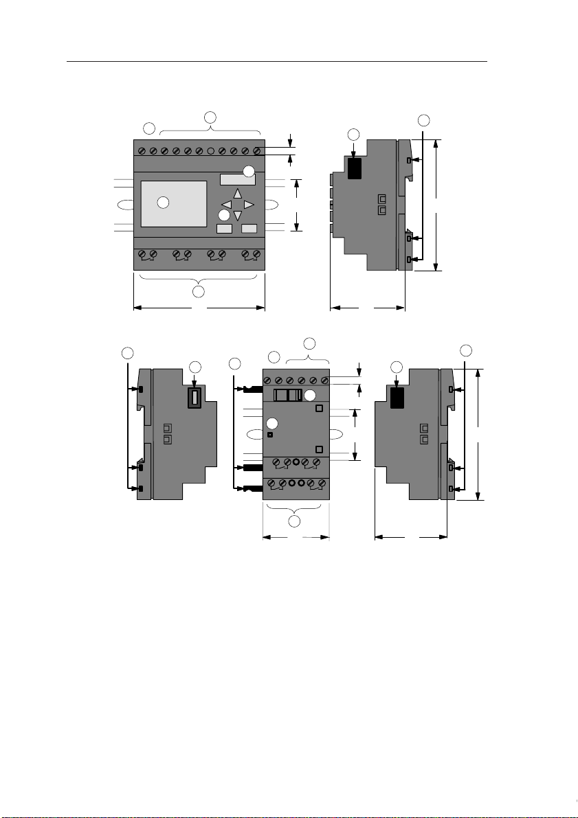
2.2 Installing/removing IDEC SmartRelay
Dimensions
The IDEC SmartRelay installation dimensions are compliant
with DIN 43880.
IDEC SmartRelay can be snap-mounted to 35 mm DIN rails
to EN 50022 or on the wall.
IDEC SmartRelay width:
• IDEC SmartRelay Basic has a width of 72 mm, which corresponds with 4 subunits.
• IDEC SmartRelay expansion modules have a width of
36 mm, which corresponds with 2 subunits.
Note
The figure below shows you an example of the installation
and removal of a FL1C-H12RCC and a digital module. The
measures shown apply to all other IDEC SmartRelay Basic
versions and expansion modules.
Warning
!
Always switch off power before you “remove” and “insert” a module
(base module, expansion module, communication module).
IDEC SmartRelay Manual 15

IDEC SmartRelay installation and wiring
2.2.1 DIN rail mounting
Mounting
How to mount a IDEC SmartRelay Basic and a digital module onto a DIN rail:
IDEC SmartRelay Basic:
1. Hook the IDEC SmartRelay Basic module onto the rail
and
2. then push down the lower end to snap it on. The mounting interlock at the rear must engage.
1
6
3
5
2
IDEC SmartRelay digital module:
3. On the right side of the IDEC SmartRelay Basic/IDEC
SmartRelay expansion module, remove the connector
cap.
4. Place the digital module onto the DIN rail on the
right-hand side of the IDEC SmartRelay Basic.
5. Slide the digital module towards the left until it contacts
the IDEC SmartRelay Basic.
4
16
IDEC SmartRelay Manual

IDEC SmartRelay installation and wiring
6. Using a screwdriver, push the interlock to the left. In its
end position the slide interlock engages in the IDEC
SmartRelay Basic.
Repeat steps 3 through 6 to mount further expansion modules.
Note
The expansion interface on the last expansion module must
be covered.
IDEC SmartRelay Manual 17

IDEC SmartRelay installation and wiring
Removal
To remove the IDEC SmartRelay:
....... if you have installed only one IDEC SmartRelay Ba-
sic:
Part
A
1. Insert a screwdriver into the eyelet at the bottom of the
slide interlock and move the latch downward.
2. Swing the IDEC SmartRelay Basic off the DIN rail.
1
2
18
2
1
4
3
AB
IDEC SmartRelay Manual

IDEC SmartRelay installation and wiring
....... if you have connected at least one expansion mod-
ule to the IDEC SmartRelay Basic:
Part
B
1. Using a screwdriver, push the integrate slide interlock to
the right.
2. Slide the expansion module off towards the right.
3. Insert a screwdriver into the eyelet at the bottom of the
slide interlock and lever it downward.
4. Swing the expansion module off the profile rail.
Repeat steps 1 to 4 for all other expansion modules.
Note
If you have connected more than one expansion module, it is advisable to start removal with the last module at the right-hand side.
Make sure that the slide interlock of the module to be installed/removed is not engaged in the next module.
IDEC SmartRelay Manual 19

IDEC SmartRelay installation and wiring
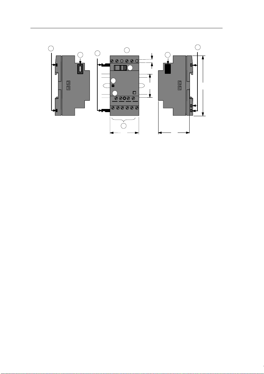
Mounting slides
2.2.2 Wall-mounting
For wall-mounting, first slide the mounting slides on the rear
side of the devices towards the outside. You can now
wall-mount the IDEC SmartRelay by means of two mounting
slides and two φ M4 screws (tightening torque 0.8 to 1.2Nm).
20
IDEC SmartRelay Manual

IDEC SmartRelay installation and wiring
Drilling template for wall-mounting
Before you can wall-mount the IDEC SmartRelay, you need
to drill holes using the template shown below.
53.5 +/– 0.2 35.5 +/– 0.2
98 +/– 0.3
1
2
2 2
All dimensions in mm
Bore hole for φ M4 screw
●
Tightening torque 0.8 to 1.2 Nm
➀ IDEC SmartRelay Basic
② IDEC SmartRelay expansion module
n x 35.5 +/– 0.2
IDEC SmartRelay Manual 21

IDEC SmartRelay installation and wiring
2.3 Wiring the IDEC SmartRelay
Wire the IDEC SmartRelay using a screwdriver with a 3-mm
blade.
You do not need wire ferrules for the terminals. Permitted
conductor cross-sections:
•1 x 2.5 mm
•2 x 1.5 mm2 for each second terminal chamber
Tightening torque: 0.4...0.5 Nm or 3...4 lbs in
Note
Always cover the terminals after you have completed the installation. To protect IDEC SmartRelay adequately from impermissible
contact to live parts, local standards must be complied with.
2.3.1 Connecting the power supply
IDEC SmartRelays (FL1C-*12RCC, FL1B-M08C2R2) are
suitable for nominal line voltages of 100 V AC/DC and 240 V
AC/DC. IDEC SmartRelays (FL1C-*12RCA, FL1BM08D2R2) are suitable for a supply voltage of 24 V AC/DC.
IDEC SmartRelays (FL1C-H12SND, FL1B-M08B1S2) are
suitable for a supply voltage of 24 V DC. IDEC SmartRelays
(FL1C-*12RCE, FL1B-M08B2R2) are suitable for a supply
voltage of 12 V AC/DC or 24 V AC/DC.
Note the information on connection in the product information document shipped with your device and the technical
specifications in Appendix A relating to permissible voltage
tolerances, line frequency and current consumption.
2
22
Note
A power failure may cause an additional edge triggering signal at
the special functions, for example.
Data of the last uninterrupted
cycle are stored in IDEC SmartRelay.
IDEC SmartRelay Manual

IDEC SmartRelay installation and wiring
Connecting IDEC SmartRelay
To connect IDEC SmartRelay to the power supply:
IDEC SmartRelay .....
with DC power supply
L+
M
ML+ I1 I2 I3 I4 I5
Protection with safety fuse
if required (recommended) for:
FL1C-H12RCE: 0.8 A
FL1C-H12SND: 2.0 A
Note
IDEC SmartRelay is a double-insulated switchgear. It is not required to connect an equipment grounding conductor.
Circuit protection with AC voltage
To suppress voltage peaks on the power supply lines, you
can install a metal oxide varistor (MOV) . Make sure that the
operating voltage of the varistor (MOV) used lies at least 20
% above the rated voltage.
IDEC SmartRelay .....
with AC power supply
L1
N
I1 I2 I3 I4L1 N
To suppress surge voltages, install varistors (MOV) with an operating voltage at
least 20 % above the rated voltage.
IDEC SmartRelay Manual 23

IDEC SmartRelay installation and wiring
2.3.2 Connecting IDEC SmartRelay inputs
Requirements
At the inputs you connect sensor elements such as: momentary switches, switches, light barriers, daylight control
switches etc.
Sensor characteristics for IDEC SmartRelay
FL1C-H12RCE
FL1C-B12RCE
FL1B-M08B2R2
I1 ... I6 I7, I8 I1 ... I6 I7, I8
Signal status 0 < 5 VDC < 5 VDC < 5 VDC < 5 VDC
Input current < 1.0 mA < 0.05 mA < 1.0 mA < 0.05 mA
Signal status 1 > 8 V DC > 8 V DC > 8 V DC > 8 V DC
Input current > 1.5 mA > 0.1 mA > 1.5 mA > 0.1 mA
FL1C-H12SND
FL1B-M08B1S2
FL1C-
H12RCA/
FL1C-
B12RCA (AC)
FL1B-M08
D2R2 (AC)
Signal status 0 < 5 V AC < 5 V DC < 40 V AC < 30 V DC
Input current < 1.0 mA < 1.0 mA < 0.03 mA < 0.03 mA
Signal status 1 > 12 V AC > 12 V DC > 79 V AC > 79 V DC
Input current > 2.5 mA > 2.5 mA > 0.08 mA > 0.08 mA
FL1C-
H12RCA/
FL1C-
B12RCA (DC)
FL1B-M08
D2R2 (DC)
FL1C-
H12RCC/
FL1C-
B12RCC (AC)
FL1B-M08
C2R2 (AC)
FL1C-
H12RCC/
FL1C-
B12RCC (DC)
FL1B-M08
C2R2 (DC)
Note
The digital inputs of FL1C-H12RCC/FL1C-B12RCC are divided
into two groups, each consisting of four inputs. Within the same
group, all inputs must be operated on the same phase. Different
phases are only possible between the groups.
Example:
Inputs within the FL1B-M08C2R2 may not be connected to different phases.
I1 to I4 on phase L1, I5 to I8 on phase L2.
24
IDEC SmartRelay Manual

Sensor connections
L1
N
NL1
C
Connecting glow lamps and 2-wire proximity switches (Bero)
to FL1C-H12RCC/FL1C-B12RCC or FL1B-M08C2R2 (AC)
Take the quiescent current of any 2-wire proximity switches
used into account. The level of the quiescent current of some
2-wire proximity switches is high enough to trigger a logical
"1" signal at the IDEC SmartRelay input. You should therefore compare the quiescent current of the proximity switches
with the technical data of inputs Appendix A.
IDEC SmartRelay installation and wiring
IDEC SmartRelay Manual 25

IDEC SmartRelay installation and wiring
Restrictions
• Signal status transitions 0 → 1 / 1 → 0
After a 0 to 1 or 1 to 0 transition, the signal must remain constant at the input at least for the duration of one program cycle, so that IDEC SmartRelay can detect the new signal status.
The program execution time is determined by the size of the
circuit program. Appendix B contains a benchmark test routine that you can use to determine the current scan cycle
time.
Special features of FL1C-H12RCE/FL1C-B12RCE and FL1CH12SND
• High-speed inputs: I5 and I6
These versions are also equipped with high-speed counting
inputs (Up/down counters, Frequency triggers). The restrictions mentioned earlier do not apply to these high-speed inputs.
Note
The high-speed inputs I5 and I6 are the same as in the previous
versions FL1B, i.e. a circuit program that is written in these versions can be transferred to the new FL1C units by means of the programming software WindLGC, without any changes to these features.
26
Expansion modules do not have high-speed inputs.
• Analog inputs: I7 and I8
The inputs I7 and I8 of IDEC SmartRelay versions FL1CH12RCE/FL1C-B12RCE and FL1C-H12SND can be used
both as standard digital inputs and as analog inputs. The input mode is defined in the IDEC SmartRelay circuit program.
The inputs I7 / I8 provide digital functions, and the inputs AI1
and AI2 provide analog functions.
See also Chapter 4.1.
IDEC SmartRelay Manual

IDEC SmartRelay installation and wiring
Note
The FL1B-J2B2 expansion module provides further analog inputs.
Always use twisted and shielded cables for analog signals, and
keep these as short as possible.
Sensor connections
To connect sensors to the IDEC SmartRelay :
FL1C-H12RCA / FL1C-B12RCA / FL1C-H12RCE /
FL1C-B12RCE/ FL1C-H12SND
L+
M
ML+ I1 I2 I3 I4 I5 I8
The inputs of these devices not isolated
and therefore require a common reference
potential (chassis ground ).
At the FL1C-H12RCE/FL1C-B12RCE and
FL1C-H12SND modules, you can tap analog signals between the supply voltage and
chassis ground.
FL1C-H12RCC / FL1C-B12RCC
L3
L2
L1
N
NL1 I1 I2 I3 I4 I5 I6
IDEC SmartRelay Manual 27
The inputs of these devices are arranged in
2 groups, each consisting of 4 inputs. Different phases are only possible between
blocks, but not within the blocks.

IDEC SmartRelay installation and wiring
Warning
!
Current safety regulations (VDE 0110, ... and IEC 61131-2, ... as
well as cULus) do not permit the connection of different phases to
an AC input group (I1 to I4 or I5 to I8) or to the inputs of a digital
module.
FL1B-J2B2
L
M
ML+
3
RUN/STOP
PE
ML+
PE
PE terminal for connecting earth and the shielding of the analog
measuring cable
➀ Earth
② Cable shielding
➂ DIN rail
1
L
M
+
Current
0...20mA
Current measurement
28
U1 I2 M2 U2I1 M1
2
Reference
current
M
Voltage measurement
IDEC SmartRelay Manual

IDEC SmartRelay installation and wiring
Input Internal Circuit
FL1C-H12RCC / FL1C-B12RCC / FL1B-M08C2R2
Digital AC/DC Input
390kΩ 390kΩ
I1~I8
100nF
N
When using the AC two-wire sensor
AC
2-wire
Sensor
R4
Internal
Circuit
62kΩ
I1 to I8
N
100 to 240 V AC
L1
IDEC SmartRelay Manual 29

IDEC SmartRelay installation and wiring
FL1C-H12RCA / FL1C-B12RCA / FL1B-M08D2R2
Digital AC/DC Input
+5V
Internal Circuit
I1~I8
4.3kΩ
510Ω100nF
P2
When using the AC two-wire sensor
AC
2-wire
Sensor
Internal
Circuit
I1 to I8
R3
P1
240 V AC
P2
30
IDEC SmartRelay Manual

IDEC SmartRelay installation and wiring
FL1C-H12RCE / FL1C-B12RCE / FL1C-H12SND / FL1B-M08B2R2/
FL1C-M08B1S2
Digital DC Input
3.3kΩ
I1~I8
2kΩ100nF
M
Internal
Circuit
FL1C-H12RCE / FL1C-B12RCE / FL1C-H12SND / FL1B-J2B2
Analog Input (0-10V)
I7, I8
(U1, U2)
M
(M1, M2)
38kΩ
10nF
38kΩ
+5V
Internal
Circuit
FL1B-J2B2
Analog Input (0-20mA)
Max 125Ω
I1, I2
125Ω 10nF
M1, M2
IDEC SmartRelay Manual 31
Internal
Circuit

IDEC SmartRelay installation and wiring
2.3.3 Connecting outputs
FL1C-B12RCC / FL1C-B12RCA / FL1C-H12RCC / FL1C-H12RCA/
FL1C-H12RCE / FL1C-B12RCE
These units are equipped with relay outputs. The potential of
the relay contacts is isolated from the power supply and the
inputs.
Requirements for relay outputs
You can connect various loads to the outputs, e.g. lamps,
fluorescent lamps, motors, contactor relays etc. For information on the properties required for the loads connected to the
these units, refer to Appendix A.
Connecting
This is how you connect the load:
1 2
1 2
Q5 Q6
1 2
1 2
Q1 Q2
32
load
Protection with automatic circuit-breaker, max. 16 A, characteristics
B16, e.g.: Power circuit-breaker 5SX2 116-6 (if required)
load
IDEC SmartRelay Manual

IDEC SmartRelay installation and wiring
Q1 Q2MM
Q5 Q6MM
load
Load: 24 V DC, 0.3 A max.
load
IDEC SmartRelay with transistor outputs
IDEC SmartRelay versions with transistor outputs can be
identified by the fact that the letter R is missing from their
type name. The outputs are short circuit-proof and overload-proof. An auxiliary load voltage supply is not necessary,
because IDEC SmartRelay supplies the load voltage.
Requirements for transistor outputs
The load connected to IDEC SmartRelay must have the following characteristics:
• The maximum switched current is 0.3 A per output.
Connecting
This is how you connect the load to a IDEC SmartRelay with
transistor outputs:
IDEC SmartRelay Manual 33

IDEC SmartRelay installation and wiring
Output Internal Circuit
FL1C-H12RCC / FL1C-B12RCC / FL1C-H12RCA / FL1C-B12RCA /
FL1C-H12RCE/ FL1C-B12RCE / FL1B-M08B2R2 / FL1B-M08C2R2/
FL1B-M08D2R2
Relay Output
Internal Circuit
+24V
2
Internal
Circuit
47kΩ
27kΩ
FL1C-H12SND / FL1B-M08B1S2
Transister Output (Source)
+24V
Internal
Circuit
10kΩ10nF 10nF
Q1~Q4
1
Internal Circuit
Q1~Q4
M
34
IDEC SmartRelay Manual

IDEC SmartRelay installation and wiring
2.4 Switching on the IDEC SmartRelay / Power On
IDEC SmartRelay does not have a power switch. The reaction of IDEC SmartRelay during startup depends on
• Whether a circuit program is stored in IDEC SmartRelay
• Whether a memory cartridge (card) is inserted
• Whether this is a IDEC SmartRelay version without display unit (FL1C-B12...)
• The status of IDEC SmartRelay at the time of power failure.
All possible reaction of IDEC SmartRelay are described on
the following page.
Note
After power-up, the FL1C performs initialization. After completing
initialization, the FL1C is ready to start to run. During initialization,
a sandglass is displayed on the CPU module with display, or the
LED is lit red on the CPU module without display.
Initialization time (regardless of expansion module)
When a memory cartridge is installed: Max. 10 sec
When a memory cartridge is not installed: Max. 9 sec
IDEC SmartRelay Manual 35

IDEC SmartRelay installation and wiring
Before power off After power on
No Program
Press ESC
No program in
memory
Mo 09:00
2003-01-27
I:
0.. 123456789
1..0123456789
2..01234
Q:
0.. 12345678
9
1..0123456
IDEC SmartRelay
in RUN mode
Program in
memory
B3:
Par = 0300
Cnt = 0028
B1
&
Q1
or
(empty)
(with program)
or
(empty)
(with program)
or
(empty)
(with program)
No program
Press ESC
>Program..
Card..
Clock..
Start
Mo
Mo 09:00
09:00
2002-01-31
2002-01-31
I:
0.. 123456789
1..0123456789
2..01234
IDEC SmartRelay
in RUN mode
Mo 09:00
2002-01-31
I:
0.. 123456789
1..0123456789
2..01234
>Program..
Card..
Clock..
Start
>Program..
Card..
Clock..
Start
With stored
program from
IDEC SmartRelay
......
with a program
copied from the
memory cartridge
(card) in
IDEC SmartRelay
......
With stored program from IDEC
SmartRelay
with a program
copied from the
memory cartridge
(card) in
IDEC SmartRelay
36
IDEC SmartRelay Manual

IDEC SmartRelay installation and wiring
You can also memorize four simple rules for starting IDEC
SmartRelay :
1. If neither the IDEC SmartRelay nor the inserted memory
cartridge (card) contains a circuit program, the IDEC
SmartRelay (with display unit ) reports: 'No Program /
Press ESC'.
2. A circuit program on the memory cartridge (card) is au-
tomatically copied to IDEC SmartRelay. The circuit program in the IDEC SmartRelay is overwritten.
3. If there is a circuit program in IDEC SmartRelay or on the
memory cartridge (card), IDEC SmartRelay adopts the
operational state it had prior to POWER-OFF. Versions
without display unit (FL1C-B12...) automatically change
from STOP to RUN (LED changes from red to green).
4. If you have enabled retentivity at least for one function,
or a function is permanently retentive, the current values
are retained at POWER-OFF.
Note
When a power failure occurs while you are entering a circuit program, the program in IDEC SmartRelay will be deleted after power
is returned.
Before you modify the circuit program, you should therefore save a
backup copy of your original to a memory cartridge (card) or to a
computer (WindLGC).
IDEC SmartRelay Manual 37

IDEC SmartRelay installation and wiring
IDEC SmartRelay Basic operating states
IDEC SmartRelay Basic/Pure knows two operating states:
STOP and RUN
STOP RUN
• The display shows:
'No Program'
(not FL1C-B12...)
• Switching IDEC SmartRelay
to programming mode
(not FL1C-B12...)
• LED is red
(only FL1C-B12...)
Action of IDEC SmartRelay:
• The inputs data are not
fetched.
• The circuit program is not executed
• The relay contacts are permanently open or the transistor outputs are switched off
• Display: Screen mask for
• Switching IDEC SmartRelay
• LED is green
Action of IDEC SmartRelay:
• IDEC SmartRelay reads the
• IDEC SmartRelay uses the
• IDEC SmartRelay switches
monitoring I/Os and messages (after START in the main
menu)
(not FL1C-B12...)
to parameter assignment
mode
(not FL1C-B12...)
(only FL1C-B12...)
status of the inputs
circuit program to calculate
the status of the outputs
the relay/transistor outputs
on or off
IDEC SmartRelay expansion modules, operating states
IDEC SmartRelay expansion modules know three operating
states: The LED is lit green, red or orange.
LED is lit
Green (RUN) Red (STOP) Orange
Initialization phase
of the expansion
module
IDEC SmartRelay Manual
38
The expansion module communicates
with the device to its
left
The expansion module does not communicate with the
device to its left

3 Programming IDEC SmartRelay
Getting started with IDEC SmartRelay
Programming in our context refers to the creation of a circuit
program. A IDEC SmartRelay circuit program is actually no
more than a circuit diagram presented in a slightly different
form!
We have adapted this presentation to the IDEC SmartRelay
display field. In this chapter we are going to show you how to
use IDEC SmartRelay to create the IDEC SmartRelay circuit
programs for your application.
At this point, we once again refer to WindLGC, which is the
IDEC SmartRelay programming software you can use to
quickly and easily create, test, modify save and print the circuit programs. The topics in this manual relate only to the
creation of circuit programs on the actual IDEC SmartRelay,
because the programming software WindLGC already contains an extensive Online Help. See also Chapter 7.
Note
IDEC SmartRelay versions without display unit, i.e. the FL1CB12RCE, FL1C-B12RCA and FL1C-B12RCC units, do not have an
operator panel and display unit. They are primarily designed for use
in small machine and process equipment engineering systems for
series production.
FL1C-B12... versions are not programmed directly at the unit. Instead, the circuit program is downloaded to this device by means of
WindLGC or memory cartridges (cards) of other IDEC SmartRelay
FL1C units.
IDEC SmartRelay versions without display can not write data to
memory cartridges (cards).
See Chapter 6, 7 and Appendix C.
IDEC SmartRelay Manual 39

Programming IDEC SmartRelay
A small example in the first part of this chapter introduces the
operating principle of IDEC SmartRelay.
• We shall first show you the meaning of two basic terms,
namely the connector and the block.
• In the next step, we shall create a circuit program based
on a simple conventional circuit, which you ...
• can enter directly in IDEC SmartRelay in the third step.
It will take you only a few pages of this manual store your first
executable circuit program in the IDEC SmartRelay unit.
With a suitable hardware (switches etc.), you will then be
able to carry out first tests.
40
IDEC SmartRelay Manual

Programming IDEC SmartRelay
L+ M I13I14I15 I16
Q11Q9Q12
Q10
RUN/STOP
L+ M
A!3
RUN/STOP
L+ M I1 I2 I3 I4 I5 I6
Q1 Q2 Q3 Q4
AI1 AI2 L+ M I9 I10 I11I12
Q7
Q5
Q8
Q6
RUN/STOP
M3U3AI4M4 U4
1 2 1
2
1 2 1 2
1 2 1 2 1 2 1 2
1 2 1 2
1 2 1 2
PE
INPUT 2x (..10 V/..20 mA)
L+ M
Inputs
Outputs Analog Inputs
3.1 Connectors
The IDEC SmartRelay is equipped with inputs and outputs
Example of a configuration with several modules:
Each input is identified by the letter I plus a number. When
you take a look at the IDEC SmartRelay from the front, you
can see the input terminals at the top. Only the analog modules FL1B-J2B2 has the inputs at the bottom.
Each output is identified by the letter Q plus a number. In the
figure, you can see the output terminals at the bottom.
IDEC SmartRelay Manual 41

Programming IDEC SmartRelay
▲
Note
IDEC SmartRelay can recognize, read and switch the I/O of all expansion modules, regardless of their type. The I/O are presented in
the installation order of the modules.
The following I/Os and marker blocks are available for the creation
of your circuit program: I1 to I24, AI1 to AI8, Q1 to Q16, M1 to M24
and AM1 to AM6. Also available are the shift register bits S1 to S8,
4 cursor keys C
X1 to X16. More details are found in Chapter 4.1.
The following applies to the inputs I7 and I8 of FL1C-H12RCE/
FLC1-B12RCE and FL1C-H12SND versions: If Ix is used in the circuit program, this input signal is digital; signals at AIx are analog.
Input AIx can only represent the connector that is actually capable
of handling analog signals.
▲
▲, C , C▼ and C , as well as 16 blank outputs
IDEC SmartRelay's connectors
The term connector refers to all connections and states in
IDEC SmartRelay.
The I/O status can be '0' or '1'. Status '0' means that the input
does not carry a voltage. Status '1' means that the input carries voltage.
We have introduced 'hi', 'lo' and 'x' connectors to make it
easier for you to create the circuit program:
'hi' (high) is assigned the status '1',
'lo' (low) is assigned the status '0'.
You do not have to use all the of connectors of a block. The
circuit program automatically assigns the unused connectors a status that ensures proper functioning of the relevant
block. If you prefer to do so, you can identify unused connectors with an 'x'.
For information on the meaning of the term “block”, refer to
Chapter 3.2.
42
IDEC SmartRelay Manual

Programming IDEC SmartRelay
IDEC SmartRelay knows the following connectors:
Con-
nectors
Inputs FL1C-H12RCC
Outputs Q1...Q4 Q5 ...
lo Logical '0' signals (off)
hi Logical '1' signals (on)
x An existing connection that is not used
DM: Digital module.
AM: Analog module.
IDEC SmartRelay Basic / Pure DM AM
FL1C-B12RCC
FL1C-H12RCA
FL1C-B12RCA
FL1C-H12RCE
FL1C-B12RCE
FL1C-H12SND
Two groups:
I1... I4 and
I5 ... I8
I1... I6, I7, I8
AI1, AI2
I9 ... I24 AI1...AI8
I9 ... I24
Q16
AI3...AI8
none
IDEC SmartRelay Manual 43

Programming IDEC SmartRelay
I1
I2
x
≥ 1
Q
x
Inputs I1 and I2 are here connected to
the OR block. The last two inputs of
the block remain unused and are identified be the creator of the circuit program with an ‘x’.
3.2 Blocks and block numbers
This chapter shows you how to use IDEC SmartRelay elements to create complex circuits and how blocks and I/O are
interconnected.
In Chapter 3.3 we are going to show you how to transform a
conventional circuit to obtain a IDEC SmartRelay circuit program.
Blocks
A block in IDEC SmartRelay represents a function that is
used to convert input information into output information.
Previously you had to wire the individual elements in a control cabinet or terminal box.
When you create the circuit program, you interconnect the
blocks. To do so, simply select the connection you require
from the Co menu The menu name Co is an abbreviation of
the term “Connector”.
Logic operations
The most elementary blocks are the logic operations:
• AND
•OR
• ...
44
These special functions offer you a significantly higher performance:
• Current impulse relay
• Up/down counter
• On-delay
• Softkey
• ....
In Chapter 4 you will find a full list of the IDEC SmartRelay
functions.
IDEC SmartRelay Manual

Programming IDEC SmartRelay
View of blocks on the IDEC SmartRelay display
The figure below shows a typical view of the IDEC SmartRelay display. As you can see, it can show only one block at a
time. We have therefore introduced block numbers to help
you check the circuit structure.
View of the IDEC SmartRelay display
A further block is
connected at this
point
Input
x
B2
≥ 1
I3
x
Block number assigned by IDEC
SmartRelay
B1
Q1
This connector is not required
Assigning a block number
IDEC SmartRelay assigns each new block a circuit program
a block number.
IDEC SmartRelay uses these block numbers to indicate the
block interconnections. Hence, these numbers primarily represent a help for your orientation in the circuit program.
B2
x
≥ 1
I1
I2
B1
I3
B3
x
≥ 1
I4
I5
B1
I6
Scrolling the circuit program using the key
Block numbers
These blocks are
interconnected
x
≥ 1
B2
B3
x
Block
B1
Q1
▲
Output
B1
Q1
IDEC SmartRelay Manual 45

Programming IDEC SmartRelay
The figure above shows you three views of the IDEC SmartRelay display, which represent the circuit program. As you
can see, IDEC SmartRelay interconnects the blocks using
their numbers.
Advantages of the block numbers
You can connect almost any block to an input of the current
block by means of its block number. In this way, you can reuse the interim results of logical or other operations, reduce
programming effort, save memory space and clean up your
circuit layout. To do so, however, you need to know how
IDEC SmartRelay has named the blocks.
Note
We advise you to create an organizational program chart. You will
find this a valuable help when you create the circuit program, because you can enter all block numbers assigned by IDEC SmartRelay in this chart.
By using the WindLGC software to program the IDEC SmartRelay,
you can directly create a function chart of your circuit program.
WindLGC also allows you to assign 8-character names to up to 64
blocks, and to view these on the IDEC SmartRelay display in parameter assignment and programming mode (see Chapter 3.2).
46
IDEC SmartRelay Manual

Programming IDEC SmartRelay
The load E1 is switched on
and off by means of the
switches (S1 OR S2) AND S3.
Relay K1 picks up when the
condition (S1 OR S2) AND S3
is met.
K1
S1
K1
S2
E1
S3
3.3 The way to IDEC SmartRelay, starting with the circuit diagram
View of a circuit diagram
You know, of course, how a circuit logic is represented in a
circuit diagram. Nevertheless, here is an example:
Creating this circuit with IDEC SmartRelay
In IDEC SmartRelay you create a circuit logic by interconnecting blocks and connectors:
L
1
S1 ... S3
Wiring of the inputs
Circuit program in IDEC SmartRelay
I1
I3
&≥ 1
I2
x
N
IDEC SmartRelay Manual 47
Wiring of the outputs
x
Q1

Programming IDEC SmartRelay
I3
x
Q1
&
I3
x
Q1
&≥ 1
I1
I2
x
Note
Although you have four inputs available for logic operations (Basic
functions, see Chapter 4.2), most of the views will only show three
inputs for reasons of clarity. You program this fourth input and assign parameters just like you do with the other three inputs.
To create a circuit logic in IDEC SmartRelay, start at the output.
The output is the load or relay that is to be switched.
Convert the circuit logic into blocks by working through the
circuit, starting at the output and ending at the input:
Step 1: The make contact S3 is interconnected in series to
output Q1 and to a further circuit element. A series connection corresponds with the AND block:
Step 2
: S1 and S2 are connected in parallel. A parallel circuit
corresponds with the OR block:
Unused inputs
48
The circuit program automatically assigns the unused connectors a status that ensures proper functioning of the relevant block. If you like, you can label unused connectors with
an 'x' identifier.
In our example we shall use only two inputs of the OR block
and two inputs of the AND block; the relevant unused third
and fourth inputs are identified at the connector with an 'x'.
Now connect the I/Os to the IDEC SmartRelay .
IDEC SmartRelay Manual

Wiring
L1
N
S3S2S
1
L1
N
NL1 I1 I2 I3 I4
1 2
Q1
Input wiring
Output wiring
Load
Connect the switches S1 to S3 to the screw terminals of your
IDEC SmartRelay :
• S1 to connector I1 of IDEC SmartRelay
• S2 to connector I2 of IDEC SmartRelay
• S3 to connector I3 of IDEC SmartRelay
The output of the AND block controls the relay at output Q1.
The load E1 is connected to output Q1.
Wiring example
The following figure shows you the wiring, based on the
FL1C-H12RCC/-B12RCC.
Programming IDEC SmartRelay
IDEC SmartRelay Manual 49

Programming IDEC SmartRelay
3.4 The 4 golden rules for the operation of IDEC SmartRelay
Rule 1
Changing the operating mode
• You create the circuit program in programming mode.
After power is on, and when the display shows “No Program / Press ESC”, press the ESC key to select programming mode.
• Timer and parameter values of an existing circuit program can be edited both in parameter assignment
mode and in programming mode. During parameter
assignment the IDEC SmartRelay is in RUN mode, i.e.
it continues execution of the circuit program (see
Chapter 5). To work in programming mode, you need to
terminate the circuit program by calling the “Stop” command.
• Select the 'Start' command on the main menu to set RUN
mode.
• When the system is in RUN, you can return to parameter
assignment mode by pressing the ESC key.
• When parameter assignment mode is open and you
want to return to programming mode, select the “Stop”
command from the parameter assignment menu, and
confirm “Stop Prg” prompt with “Yes”. To do so, move
the cursor to “Yes” and confirm with OK.
For more details on operating modes, refer to Appendix D.
Rule 2
Outputs and inputs
• Always create your circuit program by working from the
output to the input.
• You can connect an output to several inputs, but not the
same input to several outputs.
• Within the same program path you may not connect an
output to an upstream input. For such internal recursions
you should interconnect memory markers or outputs.
50
IDEC SmartRelay Manual

Rule 3
Cursor and cursor movement
The following applies when you edit a circuit program:
• You can move the cursor when it appears in the form of
an underscore:
- Press , , ▼ or ▲ to move the cursor in the circuit
▲
▲
program.
- Press OK to change to "Select connector/block"
- Press ESC to exit programming mode.
• You select a connector/block
• when the cursor appears as solid square
- Press ▼ or ▲ to select a connector or a block.
- Confirm with OK.
- Press ESC to return to the previous step.
Rule 4
Planning
• Before you start to create a circuit program, you should
either first create design on paper or program IDEC
SmartRelay directly using WindLGC.
• IDEC SmartRelay can only save complete and faultless
circuit programs.
Programming IDEC SmartRelay
IDEC SmartRelay Manual 51

Programming IDEC SmartRelay
3.5 Overview of the IDEC SmartRelay menus
Programming mode
Main menu Programming menu
>Program..
Card..
Clock..
Start
= IDEC
SmartRelay
Parameter assignment mode
Parameter assignment menu
OK
ESC
ESC
ESC
>Edit..
Clear Prg
Password
OK
Transfer menu
> Card
Card
CopyProtect
OK
Real-time clock menu
>Set Clock
S/W Time
Sync
>Stop
Set Param
Set Clock
Prg Name
52
For more details on these menus, refer to Appendix D.
IDEC SmartRelay Manual

Programming IDEC SmartRelay
No Program
Press ESC
>Program..
Card..
Clock..
Start
IDEC SmartRelay’s main menu
>Edit..
Clear Prg
Password
IDEC SmartRelay’s programming menu
3.6 Writing and starting the circuit program
After you have designed a circuit, you want to write it to your
IDEC SmartRelay. The small example below shows how to
do this.
3.6.1 Select programming mode
You have connected the IDEC SmartRelay to the power supply and switched it on. The display now shows you the message:
Switch the IDEC SmartRelay to programming mode by
pressing the ESC. This will take you to the main menu of the
IDEC SmartRelay:
IDEC SmartRelay Manual 53
The first character in the first line is the ">" cursor. Press ▲
and ▼ to move the ">" cursor up and down. Move it to "Program.." and confirm with OK. IDEC SmartRelay opens the
programming menu.

Programming IDEC SmartRelay
>Edit Prg
Edit Name
Memory?
The Edit menu of IDEC SmartRelay
Q1
The first output of IDEC SmartRelay
Here you can also move the ">" cursor by pressing ▲ and ▼.
Move the ">" cursor to "Edit.." (for editing, i.e. input) and confirm with OK.
Move the ">" cursor to "Edit Prg" (for editing the circuit program) and confirm with OK. IDEC SmartRelay now shows
you the first output:
You are now in programming mode. Press ▲ and ▼ to select
the other outputs. Now start to edit your circuit program.
54
Note
Because we have not yet saved a password for the circuit program
in IDEC SmartRelay, you can directly enter editing mode. When
you select “Edit Prg” after you have saved a password-protected
circuit program, you are prompted to enter a password and to confirm it with OK. You can only edit the program after you have entered the correct password (see Chapter 3.6.5.).
IDEC SmartRelay Manual

Programming IDEC SmartRelay
K1
S1
K1
S2
E1
The load is switched on with
S1 OR S2. IDEC SmartRelay
interprets this parallel circuit as
an ‘OR’ logic, because S1 OR
S2 switches on the output.
I1
I2
x
Q1
≥ 1
3.6.2 The first circuit program
Let us now take a look at the following parallel circuit consisting of two switches.
Circuit diagram
The corresponding circuit diagram:
Translated into a IDEC SmartRelay circuit program this
means: Relay K1 is at output Q1 is controlled by means of
an OR block.
Circuit program
S1 is connected to the I1 and S2 to the I2 input connector of
the OR block.
The corresponding layout of the circuit program in IDEC
SmartRelay:
IDEC SmartRelay Manual 55

Programming IDEC SmartRelay
L1 N I4 I5 I6I7I8
Q1 Q2 Q3 Q4
L1
N
S1
S2
L
N
I1I1 I3I1I1 I1I1I1I2
1 2 1 2 1 2 1 2
Q1
The first IDEC SmartRelay output
Wiring
The corresponding wiring:
S1 switches input I1, while S2 switches input I2. The load is
connected to the relay Q1.
3.6.3 Circuit program input
Let us now write the circuit program, starting at the output
and working towards the input. IDEC SmartRelay initially
shows the output:
56
IDEC SmartRelay Manual

Programming IDEC SmartRelay
▲▲▲
Q1
-
The cursor indicates your current
position in the circuit program.
Q1
Co
The cursor is displayed as a solid
square: You can now select a connector or a block
&
B1
Q1
The AND is the first block of the basic
functions list.
The solid square cursor prompts you
to select a block.
You will see an underscore below the Q in Q1, which is the
cursor. The cursor indicates your current position in the circuit program. You can move the cursor by pressing the ▲,
▼, and keys. Now press the key. The cursor moves
to the left.
At this point you enter only the first (OR) block. Press OK to
select editing mode.
The cursor no longer appears in the form of an underscore;
but instead as a flashing solid square. IDEC SmartRelay offers you here various options.
Select GF (basic functions) by pressing the ▼ key until GF
appears, and confirm with OK. IDEC SmartRelay now shows
the first block from the list of basic functions:
IDEC SmartRelay Manual 57

Programming IDEC SmartRelay
≥ 1
B1
Q1
The solid square cursor is still positioned on the block.
≥ 1
B1
Q1
B1
≥ 1
Q1
The display now shows:
Block
number
Your complete circuit
program layout
≥ 1
B1
Q1
Co
The display now shows:
≥ 1
B1
Q1
x
The display now shows:
Now press ▼ or ▲ until the OR block appears on the display:
Press OK to confirm your entries and exit the dialog.
You have now entered the first block. Each new block is automatically assigned a block number. The only thing left to
do is to interconnect the block inputs. This is how it is done:
Press OK.
58
Select the Co list: Press OK
IDEC SmartRelay Manual

Programming IDEC SmartRelay
≥ 1
Q1
I1
B1
≥ 1
B1
Q1
≥ 1
Q1
I1
I1
B1
Your complete circuit program
in IDEC SmartRelay up to now:
The display now shows:
The first element of the Co list is the "Input not used" character, namely the 'x'. Press ▼ or ▲ to select input I1.
Note
Press ▼ to go the start of the Co list: I1, I2 .... to lo, then again 'x'.
Press ▲ to go to the end of the Co list: lo, hi, Q ..... to I1, and once
again 'x'.
Press OK. I1 is now connected to the input of the OR block.
The cursor jumps to the next input of the OR block.
IDEC SmartRelay Manual 59
Now you connect input I2 to the input of the OR block. You
already know how to do this:
1. Switch to editing mode: Press OK
2. To select the Co list: Press ▼ or ▲
3. To confirm the Co list with: Press OK
4. To select I2: Press ▼ or ▲
5. To apply I2: Press OK

Programming IDEC SmartRelay
≥ 1
B1
Q1
≥ 1
Q1
I1
I1
B1
I2
I2
The display now shows:
Your circuit program layout in
IDEC SmartRelay up to now
≥ 1
Q1
I1
B1
I2
Q1B1
x
The display now shows: This is the layout of your circuit
program
I2 is now connected to the input of the OR block:
We do not need the last two inputs of the OR block for this
circuit program. You can mark the unused inputs with an 'x'.
Enter the 'x' character twice:
1. Switch to editing mode: Press OK
2. To select the Co list: Press ▼ or ▲
3. To accept the Co list: Press OK
4. To select 'x': Press ▼ or ▲
5. To apply x: Press OK
IDEC SmartRelay returns to output Q1.
60
IDEC SmartRelay Manual

Programming IDEC SmartRelay
≥ 1
B1
Q1
I2
I3
x
I1
≥ 1
B1
Q1
I2
I3
≥ 1
Q1
I2
B1
I3
x
x
I1
I1
The display now shows: Your circuit program layout
▲
▲
Note
You can invert individual inputs of the basic and special functions,
i.e. if an input carries a logical “1" signal, the circuit program will output a logical “0"; vice versa, a logical “0" is inverted into a logical “1"
signal.
To invert an input, move the cursor to the relevant position, e.g.:
Confirm with
Now press
Next, press ESC.
You can review your first circuit program by pressing or
to move the cursor through the circuit program.
We shall now exit circuit programming mode. This is how it
is done:
Return to the programming menu:Press ESC
IDEC SmartRelay Manual 61
OK.
▼ or ▲ to invert this input:

Programming IDEC SmartRelay
Note
IDEC SmartRelay has now saved your circuit program to nonvolatile memory. The circuit program remains in the IDEC SmartRelay
memory until you explicitly delete it.
3.6.4 Assigning a circuit program name
You can assign your circuit program a name that consists of
up to 16 uppercase/lowercase letters, numbers and special
characters.
In the programming menu:
1. To move the “>” cursor to 'Edit..': Press ▼ or ▲
2. To accept 'Edit': Press OK
3. Move the “>” cursor to 'Edit Name': Press ▼ or ▲
4. To accept 'Edit Name': Press OK
Press ▲ and ▼ to list the alphabet from A (a) to Z (z), num-
bers and special characters, either in ascending or descending order. You can select any letter, number or character.
To enter a space character, simply movie the cursor with
to the next position. This character is the first one in the list.
Examples:
Press ▼ once to select an “ A ”
▲ four times to select “ { ”, etc.
The following character set is available:
▲
ABCDEF GHI J KL MNO
PQRSTUVWXYZa b c d e
f ghi j k l mnopqr st u
vwxyz0123456789!
" #$%&' ()*+, - ./:;
<=>?@[\]^_‘{|}~
62
IDEC SmartRelay Manual

Let us assume you want to name your circuit program
“ABC”:
5. Select “A”: Press ▼
6. Move to the next letter: Press
7. Select “B”: Press ▼
8. Move to the next letter: Press
9. Select “C”: Press ▼
10. To confirm the complete name: Press OK
Your circuit program is now named “ABC”, and you are re-
turned to the programming menu.
To change the name of your circuit program, proceed in the
same way.
Note
You can change the name of the circuit program only in programming mode. You can read the name both in programming and in
parameter assignment mode
3.6.5 Password
You can protect a circuit program from unauthorized access
by assigning it a password.
To assign a password
A password may have a maximum length of 10 characters,
and consists only of uppercase letters (A to Z). Directly at the
IDEC SmartRelay, the password can be assigned, edited or
deactivated only in the “Password” menu.
In the programming menu:
1. Move the “>” cursor to 'Password': Press ▼ or ▲
2. To confirm the 'Password': Press OK
Press ▼ or ▲ to move up and down the alphabet to select
your letters. Because IDEC SmartRelay only provides uppercase letters for the password, you can quickly access to
letters “at the end” of the alphabet by using the ▲ button:
Programming IDEC SmartRelay
▲ ▲
IDEC SmartRelay Manual 63

Programming IDEC SmartRelay
Old:
No Password
New:
Old:
No Password
New:
AA
Press ▲ once to select “Z”
Press ▲ twice to select “Y”, etc.
Let us assign the password “AA” to our first circuit program.
The display now shows:
This procedure is the same as for entering the name of the
circuit program. Select “New” and enter:
3. Select “A”: Press ▼
4. To move to the next letter: Press
5. Select “A”: Press ▼
The display now shows:
▲
6. To confirm the password: Press OK
Your circuit program is now protected with the password
“AA”, and you are returned to the programming menu.
64
IDEC SmartRelay Manual

Note
Old:
AA
New:
You can cancel the input of a new password with ESC. In this case,
IDEC SmartRelay returns to the programming menu without saving
the password.
You can also set your password using WindLGC. You can not edit
a password-protected circuit program at the IDEC SmartRelay or
upload it to WindLGC unless you enter the correct password.
To allow you to create and edit a circuit program for a protected
memory cartridge (card), you first need to assign a password to this
new program (see Chapter 6.1).
Changing the Password
You need to know the current password in order to change it.
In the programming menu:
1. Move the '>' cursor to 'Password': Press ▼ or ▲
2. To confirm the 'Password': Press OK
Select “Old” and enter your old password (in our case: 'AA')
by repeating steps 3 through 6 as described earlier.
The display now shows:
Programming IDEC SmartRelay
Now you can select “New” to enter the new password, e.g.
“ZZ”:
3. Select “Z”: Press ▲
4. To move to the next letter: Press
5. Select “Z”: Press ▲
IDEC SmartRelay Manual 65
▲

Programming IDEC SmartRelay
Old:
AA
New:
Z
Z
Old:
ZZ
New:
The display now shows:
6. To confirm your new password:Press OK
Your new password “ZZ” is now set, and you are returned to
the programming menu.
Deactivating the Password
Let us assume you want to deactivate the password for
whichever reason. For example, you want to allow another
user to edit your circuit program. You must know your current password (in our example “ZZ”), same as if you were
changing it.
In the programming menu:
1. Move the '>' cursor to 'Password': Press ▼ or ▲
2. To confirm the 'Password': Press OK
Select “Old” and enter your current password under as de-
scribed in steps 3 to 5. Confirm your entries with OK.
The display shows:
66
Clear the password by leaving the input box blank:
3. To confirm the “blank” password:Press OK
The password is "cleared", and you are returned to the pro-
gramming menu.
IDEC SmartRelay Manual

Note
This action disables the password prompt, and thus permits access
without password.
Let the password prompt be deactivated for the time being, in order to accelerate progress in our further exercises and examples.
Password: Wrong Password!
When the user inputs the wrong password and confirms the
input with OK, IDEC SmartRelay does not open editing
mode, but returns to the programming menu. This repeats itself over and again until you input the correct password.
Programming IDEC SmartRelay
IDEC SmartRelay Manual 67

Programming IDEC SmartRelay
2003-01-27
Mo 09:00
I:
0.. 123456789
1..0123456789
2..01234
Q:
0.. 123456789
1..0123456
M:
0.. 123456789
1..0123456789
2..01234
ESC+Key
Display field of the IDEC SmartRelay in RUN mode
Date and current time-of-day (only
for versions with realtime clock).
This element flashes if the date and
time are not set.
Inputs I1 to I9
Inputs I10 to I19
Inputs I20 to I24
Outputs Q1 to Q9
Outputs Q10 to Q16
Markers M1 to M9
Markers M10 to M19
Markers M20 to M24
4 cursor keys for manual intervention
in the circuit program (ESC+key)
Press
Press
Press
Press
3.6.6 Switching IDEC SmartRelay to RUN mode
In the main menu, select RUN to start IDEC SmartRelay.
1. To return to the main menu: Press ESC
2. Move the '>' cursor to 'Start': Press ▲ or ▼
3. To confirm 'Start': Press OK
IDEC SmartRelay runs the circuit program and and shows
the following display:
68
IDEC SmartRelay Manual

Programming IDEC SmartRelay
Q:
0.. 123456789
1..0123456
I:
0.. 123456789
1..0123456789
2..01234
Input/output status is ‘1’:
inverted
Input/output status is ’0’:
not inverted
In this example, only the inputs I1, I15, Q8 and Q12 are set
‘high’.
What is meant by: "IDEC SmartRelay is in RUN"?
In RUN mode, IDEC SmartRelay executes the circuit program. To do so, IDEC SmartRelay first reads the status at
the inputs, determines the status of the outputs by means of
the user program, and switches these on or off according to
your settings.
This is how IDEC SmartRelay indicates the I/O status:
Status indication on the display
L1
Let us examine
this, using our example:
S1 S2
=1
I1
I:
0.. 123456789
1..0123456789
2..01234
Q1
N
IDEC SmartRelay Manual 69
I2
Q:
0.. 123456789
1..0123456
When switch S1 is closed,
the status at input I1 is hi.
IDEC SmartRelay computes
the output states by means
of the circuit program.
Output Q1 = ’1’, in this case.
When Q1 = ’1’, IDEC SmartRelay sets relay Q1, and
the load connected to Q1 is
supplied with voltage.

Programming IDEC SmartRelay
L1
N
S1
S2
K1
K1
E1
You already know the first part of
the circuit. S1 and S2 switch a relay,
which is to be used to switch on the
load E1, and to switch off the load
with a delay of 12 minutes.
≥ 1
Q1
I1
I2
x
x
Par
This is the
new block
3.6.7 Second circuit program
Up to this point, you have successfully created your first circuit, and assigned it a name and, if desired, a password. In
this section we are going to show you how to modify existing
circuit programs and how to use the special functions.
Using this second circuit program, we are going to show you
how to:
• Add a block to an existing circuit program.
• Select a block for a special function.
• Assign parameters.
Modifying circuits
We shall use the first circuit program as a basis for the second, with some slight modifications.
Let us take a first look at the circuit diagram for the second
circuit program:
70
In IDEC SmartRelay, this is the circuit program layout:
You can see the OR block and the output relay Q1 we have
already used in the first circuit program. The only difference
is the new off-delay block.
IDEC SmartRelay Manual

Editing the circuit program
Q1
B1
To move the cursor:
Press
▲
Q1
BN
IDEC SmartRelay shows
you the BN list
Switch the IDEC SmartRelay to programming mode.
As a reminder:
1. Switch the IDEC SmartRelay to programming mode
(in RUN: Press ESC to enter the parameter assignment
mode. Select the ‘Stop’ command, confirm with OK,
then move the ‘>’ cursor to ‘Yes’, and once again confirm
with OK). See page 63.
2. On the main menu, select "Program"
3. On the Programming menu, select “Edit”, confirm with
OK. Next, select “Edit Prg” and confirm with OK.
If required, enter your password at the prompt and confirm with OK.
You can now modify the current circuit program.
Adding a block to a circuit program
Move the cursor to the B in B1 (B1 is the number of the OR
block):
Programming IDEC SmartRelay
We now insert the new block at this position.
Confirm with OK.
IDEC SmartRelay Manual 71

Programming IDEC SmartRelay
Q1
SF
The SF list contains the
special function blocks.
Trg
Par
Q1
When you select a special or basic function
block, IDEC SmartRelay shows you the relevant function block. The solid square cursor
is positioned on the block. Press ▼ or ▲ to
select the required block.
R
B1
Par
Q1
B2
Before you press
‘OK’, this shows
the entry Trg
The added block is assigned the block
number B2. The cursor is positioned at
the top input of the added block.
Press ▼ to select the SF list:
Press OK.
The block of the first special function is shown:
Select your block (off-delay, see the next figure), and then
press OK:
72
The B1 block previously connected to Q1 is automatically
connected to the uppermost input of the new block. Note that
you can only interconnect digital inputs with digital outputs or
analog inputs with analog outputs. The 'old' block will otherwise be lost.
The off-delay block has three inputs. At the top is the trigger
input (Trg) you use to start the off-delay time. In our example,
the OR block B1 triggers the off-delay. You reset the time
and the output with a signal at the reset input. Set the off-delay time at parameter T of the input Par.
IDEC SmartRelay Manual

In our example we do not use the reset input of the off-delay
x
B1
Par
Q1
B2
This is what the display should now show
function, and we identify it with an 'x' connector.
Assigning block parameters
Now you set the off-delay time T:
1. Move the cursor to Par, if it not already at this position:
Press ▲ or ▼
2. Switch to editing mode: Press OK
IDEC SmartRelay shows the parameters in the parameter
assignment window:
T: The block parameter B2 is a
time function
B2 +R
T =00:00s
Programming IDEC SmartRelay
“+” means: The parameter is
shown and can be modified
in the parameter assignment
mode.
“R” means: Retentivity is enabled for this block.
Time value
To change the time value:
• Press and to position the cursor.
▲
▲
Timebase
• Press ▲ and ▼ to modify the value at the relevant posi-
tion.
• Confirm your entries with OK.
IDEC SmartRelay Manual 73

Programming IDEC SmartRelay
T=12:00m
B2 +R
T=12:00m
B2
R
or
Protection mode +:
The value of the time T can be
modified in parameter assignment mode.
Protection mode --:
The value of the time T is hidden in parameter assignment
mode
Setting the time
Set the time T = 12:00 minutes:
1. Move the cursor to the first digit: Press or
▲
2. Select the digit '1': Press ▲ or ▼
3. Shift the cursor to the second digit: Press or
▲
4. Select digit '2': Press ▲ or ▼
5. Move the cursor to the unit: Press or
▲
6. Select the timebase 'm' (for minutes): Press ▲ or ▼
Showing/hiding parameters - the parameter protection mode
If you want to show/hide the parameter and allow/prevent its
modification in parameter assignment mode:
1. Move the cursor to the protection mode: Press or
▲
2. Select the protection mode: Press ▲ or ▼
The display should now show:
▲
▲
▲
▲
3. Confirm your entries with: OK
Enabling/disabling retentivity
To decide whether you want to retain your current data after
a power failure or not:
1. Move the cursor to the retentivity setting:Press or
2. Select the retentivity setting: Press ▲ or ▼
74
▲
IDEC SmartRelay Manual
▲

Programming IDEC SmartRelay
T=12:00m
B2
T=12:00m
B2 R /
or
Retentivity R: Current data
are retained
Retentivity /: Current data are
not retained
▲
The display now shows:
3. Confirm your entries with OK
Note
For further information on the protection mode, refer to Chapter
4.3.5.
For further information on retentivity, refer to Chapter 4.3.4.
You can modify the protection mode and retentivity setting only in
programming mode, i.e. this is not possible in parameter assignment mode.
In this manual, the protection mode (“+” or “-”) and retentivity (“R”
or “/”) settings are only shown in the displays where these can actually be changed.
Verification of the circuit program
This program branch for Q1 is now completed. IDEC SmartRelay shows you the output Q1. You can once again view
the circuit program on the display. Use the keys to browse
the circuit program, i.e. press or to move from block to
block, ▲ and ▼ to move between the inputs at a block.
IDEC SmartRelay Manual 75
▲

Programming IDEC SmartRelay
2003-01-27
Mo 09:30
You can press or to scroll the pages and to monitor the I/O states.
Q1
I1
I2
x
x
Par
B1
B2
Closing the programming mode
Although you were shown how to exit the programming
mode when you created your first circuit program,
here is a reminder:
1. To return to the programming menu: Press ESC
2. To return to the main menu: Press ESC
3. To move the '>' cursor to 'Start': Press ▲ or ▼
4. To confirm 'Start': Press OK
IDEC SmartRelay is back in RUN mode:
3.6.8 Deleting a block
Let us assume you want to delete the block B2 from your circuit program and connect B1 directly to Q1.
▲
▲
76
Proceed as follows:
1. Switch the IDEC SmartRelay to programming mode
(as a reminder, refer to page 50).
2. Select ‘Edit’: Press ▲ or ▼
3. Confirm ‘Edit’: Press OK
4. Select ‘Edit Prg’: Press ▲ or ▼
5. Confirm ‘Edit Prg’: Press OK
(If required, enter your password and confirm with OK).
IDEC SmartRelay Manual

Programming IDEC SmartRelay
B2 Q1
Q1
I1
I2
x
x
Par
B1
B2
6. To move the cursor to the input of Q1, i.e. to B2, press :
7. Confirm with OK.
8. Now replace block B2 with block B1 at output Q1. The
procedure:
- Select the BN list: Press ▲ or ▼
- Accept the BN list: Press OK
- Select 'B1': Press ▲ or ▼
- Apply 'B1': Press OK
Result: Block B2 is deleted, because it is no longer used in
the circuit. Block B1 has replaced B2 directly at the output.
3.6.9 Deleting block groups
Let us assume you want to delete the blocks B1 and B2 from
the following circuit program (corresponds with the circuit
program in Chapter 3.6.7).
▲
IDEC SmartRelay Manual 77
Proceed as follows:
1. Switch the IDEC SmartRelay to programming mode
(as a reminder, refer to page 50).
2. To select 'Edit': Press ▲ or ▼
3. To confirm 'Edit': Press OK
4. To select 'Edit Prg': Press ▲ or ▼
5. To confirm 'Edit Prg': Press OK
(if required, enter your password and confirm with OK).

Programming IDEC SmartRelay
6. To move the cursor to the input of Q1, i.e. to B2, press :
B2 Q1
7. Confirm with OK.
8. Now set the connector ‘x’ at output Q1 instead of block
B2. To do so:
- Select the Co list: Press ▲ or ▼
- Accept the Co list: Press OK
- Select ‘x’: Press ▲ or ▼
- Apply ‘x’: Press OK
Result: Block B2 is deleted, because it is no longer used in
the circuit. This includes all blocks connected to B2. In this
example, block B1 also.
3.6.10 Correcting typing errors
Programming errors can be corrected easily in IDEC SmartRelay :
• Provided editing mode is not yet closed, you can revert by
one step by pressing ESC.
• If you have already configured all inputs, simply reconfig-
ure the faulty input:
1. Move the cursor to the faulty position
2. Change to editing mode. Press OK
3. Enter the correct input circuit.
You can only replace a block with a block that has exactly the
same number of inputs. However, you can delete the old
block and then insert a new one. You can choose any new
block.
▲
78
IDEC SmartRelay Manual

Programming IDEC SmartRelay
>Program..
Card..
Clock..
Start
IDEC SmartRelay opens the
main menu
>Edit..
Clear Prg
Password
IDEC SmartRelay changes to the
programming menu
Clear Prg
>No
Yes
3.6.11 Deleting the circuit program
To delete a circuit program:
1. Switch the IDEC SmartRelay to programming mode
2. On the main menu, press ▲ or ▼ to move the ‘>’ cursor
to ‘Program’. Press OK.
3. Move the ‘>’ cursor to ‘Clear Prg’: Press ▲ or ▼
4. Confirm ‘Clear Prg’: Press OK
IDEC SmartRelay Manual 79
To cancel deletion of the circuit program, leave the ‘>’ cursor
at ‘No’ and press OK.

Programming IDEC SmartRelay
Password?
ZZ
To prevent unintentional deletion
of your circuit program, you are
prompted to enter your password
(provided you have assigned
one).
If you are sure that you want to delete the circuit program
from memory:
5. Move the ‘>’ cursor to ‘Yes’: Press ▲ or ▼
6. Press OK.
7. Enter your password.
8. Press OK. The circuit program is deleted.
Note
Although you may have forgotten your password, you can still delete the circuit program by entering the wrong password three
times.
3.6.12 Summertime/wintertime conversion
You can enable or disable automatic Summertime/wintertime conversion in programming mode by calling the “Clock”
menu command.
1. Switch the IDEC SmartRelay to programming mode.
2. You are now in the main menu and want to select the
‘Clock’ menu command: Press ▲ or ▼
3. Confirm ‘Clock’: Press OK
4. Move the ‘>’ cursor to ‘S/W Time’: Press ▲ or ▼
5. Confirm ‘S/W Time’: Press OK
80
IDEC SmartRelay Manual

Programming IDEC SmartRelay
>On
Off
S/W Time:
Off
>EU
IDEC SmartRelay shows the following display:
The current setting of automatic S/W Time conversion is
shown in the bottom row. The default setting is ‘Off’: disabled.
Enabling summertime/wintertime conversion
You now want to enable this conversion and define or set its
parameters:
1. Move the ‘>’ cursor to ‘On’: Press ▲ or ▼
2. Confirm ‘On’: Press OK
The display shows:
IDEC SmartRelay Manual 81
3. Select the desired conversion: Press ▲ or ▼
What is shown on the display?:
•‘EU’ represents the start and end of European summer-
time.
•‘UK’ represents the start and end of summertime in the
United Kingdom.
•‘US’ represents the start and end of summertime in the
United States.
•‘AUS’ represents the start and end of Australian summer-
time.
•‘AUS-TAS’ represents the start and end of Australian/
Tasmanian summertime.
•‘NZ’ represents the start and end of New Zealand sum-
mertime.
• . . : Here you can enter any month, day and time zone dif-
ference.

Programming IDEC SmartRelay
The preset conversion data for EU, UK and US are found in
the table below:
Start of summertime End of summertime Time zone differ-
EU
UK Last Sunday in March:
US First Sunday in April:
AUS Last Sunday in October:
AUSTAS
NZ First Sunday in October:
.. Customizing the month and
Last Sunday in March:
02:00-->03:00
01:00-->02:00
02:00-->03:00
02:00-->03:00
First Sunday in October:
02:00-->03:00
02:00-->03:00
the day: 02:00--> 02:00 +
Time zone difference
Note
You can specify a time zone difference ∆ between 0 and 180 minutes.
Last Sunday in October:
03:00-->02:00
Last Sunday in October:
02:00-->01:00
Last Sunday in October:
02:00-->01:00
Last Sunday in March:
03:00-->02:00
Last Sunday in March:
03:00-->02:00
Third Sunday in March:
03:00-->02:00
Customizing the month and
the day: 03:00--> 03:00 Time zone difference
ence ∆
60 Min.
60 Min.
60 Min.
60 Min.
60 Min.
60 Min.
User-defined
(resolution in minutes)
82
Let us assume you want to enable European summertime/
wintertime conversion:
4. Move the ‘>’ cursor to ‘EU’: Press ▲ or ▼
5. Confirm ‘EU’: Press OK
IDEC SmartRelay Manual

IDEC SmartRelay shows the following display:
>On
Off
S/W Time:
On EU
MM-DD
+ : 01-01
- : 01-01
=000min
0
Cursor / solid square
Month (MM) and Day (DD)
Start of summertime
End of summertime
The desired time zone difference in
[min]
IDEC SmartRelay indicates that European S/W Time conversion is enabled.
User-defined parameters
If none of the parameters/conversions apply to your country,
you can customize these under menu item ‘. .’. To do so:
1. Confirm ‘On’ once again: Press OK
2. Move the ‘>’ cursor to ‘. .’: Press ▲ or ▼
3. Confirm the menu item ‘. .’ : PressOK
The display shows:
Programming IDEC SmartRelay
IDEC SmartRelay Manual 83
Let us assume you want to configure the following parameters: Start of summertime = 31st of March, end of summertime = 1st of November, time difference of 120 minutes.
This is how you can enter your data:
• Press or to move the solid square/cursor.
• Press ▲ or ▼ to change the value at the cursor position.
▲
▲

Programming IDEC SmartRelay
0
MM-DD
+ : 03-31
- : 11-01
=120 min
31. March
1. November
Time difference of 120 min
>On
Off
S/W Time:
On ..
The display shows:
• Confirm all your entries with OK.
You have now customized the summertime/wintertime con-
version. The IDEC SmartRelay display now shows:
IDEC SmartRelay indicates that summertime/wintertime
conversion is enabled, and that user-defined parameters
( ‘..’ ) have been set.
Note
To disable summertime/wintertime conversion in this menu, you
merely confirm ‘Off’ with OK.
84
IDEC SmartRelay Manual

3.6.13 Synchronization
>On
Off
Sync:
Off
>On
Off
Sync:
on
Time synchronization between IDEC SmartRelay and the
connected expansion modules can be enabled/disabled in
programming mode by means of the real-time clock menu
(“Clock” menu item).
1. Switch the IDEC SmartRelay to programming mode.
2. You are now in the main menu, and want to select
‘Clock’: Press ▲ or ▼
3. Confirm ‘Clock’: Press OK
4. Move the ‘>’ cursor to ‘Sync’: Press ▲ or ▼
5. Apply ‘Sync’: Press OK
IDEC SmartRelay shows the following display:
The current setting of the automatic synchronization function
is displayed in the bottom row. The default setting is ‘Off’:
disabled.
Enabling synchronization
You want to enable synchronization:
1. Move the ‘>’ cursor to ‘On’: Press ▲ or ▼
2. Confirm ‘On’: Press OK
IDEC SmartRelay shows the following display:
Programming IDEC SmartRelay
When synchronization is enabled, IDEC SmartRelay transmits the time-of-day to the expansion modules once daily, after each transition to RUN mode and when the TOD is
changed after a ‘Set Clock’ is executed or after a summertime/wintertime conversion.
Note
The expansion module with this function does not have already
been released.(As of Feb. 2004)
IDEC SmartRelay Manual 85

Programming IDEC SmartRelay
3.7 Memory space and circuit dimensions
The size of a circuit program in IDEC SmartRelay is limited
by the memory space (memory used by the blocks).
Memory areas
• Program memory:
IDEC SmartRelay allows only a limited number of blocks
in your circuit program.
The second limitation is based on the maximum number
of bytes a circuit program may contain. The total number
of bytes used can be determined by adding up the number of bytes used for the relevant function blocks.
• Retentive memory (Rem):
In this area, IDEC SmartRelay stores process variables
which need to be retentive, e.g. the hours counter value.
Blocks with optional retentivity use this memory area only
if this function is actually enabled.
86
IDEC SmartRelay Manual

Programming IDEC SmartRelay
Fig. 1
Fig. 2
Caution
!
At a power failure, the logical input level may drop to zero before
IDEC SmartRelay can save the functions to the retentive memory.
In this case, the IDEC SmartRelay saves the function values determined by the zero state at its inputs of the inputs.
Example: On-delay
With an input (I1) connected to a Trg connector of an On-delay FB
as shown in Fig.1, if I1 is ON and the IDEC SmartRelay power is
turned off and on, the timer current value of the On-delay FB is
sometimes reset as shown in Fig.2.
Other FBs are shown below.
• Function blocks whose timer current value is sometimes reset.
Off-delay, On-delay, On-/Off-delay, Retentive on-delay, Interval time-delay relay/Pulse output, Edge-triggered interval timedelay relay, Operating hours counter, Asynchronous pulse
generator, Stairwell Light Switch, Dual-function switch
• Function blocks whose output is sometimes set or reset when
input (I*) is connected to a S(R) connector with NOT.
Latching relay, Current impulse relay
IDEC SmartRelay Manual 87

Programming IDEC SmartRelay
Resources available in IDEC SmartRelay
A circuit program in IDEC SmartRelay can occupy the following maximum resources:
Bytes Blocks REM
2000 130 60
IDEC SmartRelay monitors memory utilization, and offers
only those functions from the lists for which it can actually
provide sufficient memory space.
Memory requirements
The table below shows an overview of the memory requirements for the basic and special function blocks:
Function Program
memory
Basic functions
AND 12 AND with Edge Detection 12 NAND (NOT AND) 12 NAND with Edge Detection 12 OR 12 NOR (NOT OR) 12 XOR (exclusive OR) 8 NOT (Negation) 4 -
Special functions
Times
On-delay 8 3
Off-delay 12 3
On-/Off-delay 12 3
Retentive on-delay 12 3
Interval time-delay relay / Pulse output 8 3
Edge-triggered interval time-delay relay 16 4
Asynchronous pulse generator 12 3
Random generator 12 Stairwell Light Switch 12 3
Dual-function switch 16 3
Seven-day time switch 20 Twelve-month time switch 8 -
Rem
memory
(1)
88
IDEC SmartRelay Manual

Programming IDEC SmartRelay
Function Program
Counter
Up/down counter 24 5
Operating hours counter 24 9
Frequency trigger 16 Analog
Analog trigger 16 Analog differential trigger 16 Analog comparator 24 Analog value monitoring 20 Analog amplifier 12 Others
Latching relay 8 1
Current impulse relay 12 1
Message texts 8 Softkey 8 2
Shift register 12 1
(1): Bytes in the Rem memory area, if retentivity is enabled.
Utilization of memory areas
An indication of insufficient memory space is given, when the
system does not allow you to add a further block to your circuit program. IDEC SmartRelay offers you only the blocks
for which it can provide sufficient memory space. If IDEC
SmartRelay memory space is insufficient to hold any further
blocks you select from a block list, the system will deny access to this list.
If memory space is fully occupied, optimize your circuit program, or install a second IDEC SmartRelay.
memory
Rem
memory
(1)
IDEC SmartRelay Manual 89

Programming IDEC SmartRelay
Q1x
I2
B1
B2
B3
x
B4
–
20
No 1
No 2
No 3
I1
Par
B5
B6
Par
Q2
I3
I4
x
REM
Bytes
–12
REM
Bytes
Calculating memory requirements
When calculating the memory requirements of a circuit, you
must always take all individual areas of memory into account.
Example:
The sample circuit program contains:
Block no. Function Memory area
Bytes Blocks REM
B1 OR 12 1 B2 AND 12 1 B3 Seven-day time switch 20 1 B4 On-delay
B5 Stairwell Light Switch 12 1 0
B6 AND 12 1 -
Resources used by the circuit program 76 6 3
Memory space limits in IDEC SmartRe-
(1): Configured with retentivity.
lay
Still available in IDEC SmartRelay 1924 124 57
Hence, this circuit program fits into IDEC SmartRelay.
90
(1)
813
2000 130 60
IDEC SmartRelay Manual
 Loading...