

Page 1

Page 2

British Gas:
(Any internal reference to British Gas applies equally to Scottish Gas)
The British Gas RD2 is a range of cast iron floor standing gas central heating boilers.
A complete range of natural gas models is available.
The ideal replacement boiler...
Easy to install, easy to operate and easy to service. The British Gas RD2 really is the
ultimate replacement floor standing range - you can depend on it.
Proven reliability...
Proven cast iron heat exchanger engineered and refined to be the most dependable
floor standing boiler ensuring totally calm operation and quiet running, whatever the
system demands.
Complete range...
There are 7 models in the range. All models include an overheat thermostat and a Flue
Directional kit for side and top outlet installations.
Full system suitability...
All models are suitable for connection to pumped open vent central heating systems,
pumped central heating combined with pumped or gravity indirect domestic hot water
supply systems. They can also be used on sealed water systems.
Free Three Star Service Cover:
In addition to the guarantee, we will provide absolutely free a British Gas Services
Three Star Service Cover agreement to cover your complete new system during the
first year. The benefits of this cover include priority attention and a 24 hours a day 365
days a year helpline. Full details of the terms and conditions for Three Star Cover
schemes are available separately on request.
2
British Gas 100 & 125 RD2 - Installation & Servicing
Page 3

GENERAL
Table 1 - General Data
Boiler Size 100 125
Gas Supply Connection in. BSP Rc 1/2 (1/2)
Number of Boiler Sections 4 5
Flow and Return Connections Rc 1 (1" BSP)
MAXIMUM Static Water Head m (ft.) 30.5 (100) (3 bar)
MINIMUM Static Water Head m (ft.) 1.0 (3.3)
Electrical Supply (Power Consumption) 230 V ~ 50 Hz (150 W)
Fuse Rating External 3 A Internal 2A to BS4265
Water Content litre (gal.) 9.8 (2.1) 12.2 (2.7)
Dry Weight kg. (lb.) 113 (249) 136 (300)
Boiler Size Height mm (in.) 850 (33.5)
Width mm (in.) 440 (17.4)
Depth mm (in.) 533 (21.0) 600 (23.6)
Gas Type Natural 2 H
Gas Supply Pressure 20 mb
Flue duct diameter mm (in.) 100 (4.0)
Flue duct length (max) m (ft) 2 (6.5) 1 (3.25)
Table 2 - Performance Data
Boiler Size 100 125
Boiler Input Nett CV kW (Btu/h) 33.0 (112 600) 41.3 (141 000)
Gross CV kW (Btu/h) 36.6 (125 000) 45.8 (156 300)
Gas Consumption l/s (ft.
3
/h) 0.95 (120.4) 1.18 (150.5)
Boiler Output to Water
kW (Btu/h) 29.3 (100 000) 36.6(125 000)
Burner Setting Pressure (hot)
mbar (in w.g.) 11.5 (4.6) 13.2 (5.3)
Seasonal Effiiciency (SEDBUK)* Band[ ]% D[77.6]% D[77.9]%
* The value is used in the UK Government's Standard Assessment Procedure (SAP) for energy rating of dwellings.
The test data from which it has been calculated have been certified by BG plc 0087.
Note.
Gas consumption is calculated using a calorific value of 38.7
3
(1038 Btu/ft3) gross or 34.9 MJ/m3 (935 Btu/ft3) nett. To
MJ/m
obtain the gas consumption at a different calorific value:-
a. For l/s - divide the gross heat input (kW) by the gross C.V.
of the gas (MJ/m3)
3
b. For ft
/h - divide the gross heat input (Btu/h) by the gross
C.V. of the gas (Btu/ft3)
c. The appliance is preset at the factory to the nominal rating.
CAUTION.
To avoid the possibility of injury during the installation, servicing or cleaning of
Key to symbols
GB = United Kingdom
(Countries of destination)
PMS = Maximum operating pressure of water
C12 = A room sealed appliance designed for connection via
ducts to a horizontal terminal which admits fresh air to
the burner and discharges the products of combustion
to the outside through orifices which, in this case, are
concentric. The fan is down stream of the combustion
chamber.
I
= An appliance designed for use on 2nd Family gas,
2H
Group H only.
this appliance, care should be taken when handling edges of sheet steel components.
British Gas 100 & 125 RD2 - Installation & Servicing
3
Page 4

GENERAL
CONTENTS
Air Supply. ..................................................................... 7
Boiler Assembly - Exploded view ............................. 12
Boiler Clearances ......................................................... 6
Electrical Connections............................................... 23
Electrical Diagrams ............................................ 23 - 26
Electrical Supply ........................................................... 8
Extension Ducts - Fitting ........................................... 21
Fault Finding ............................................................... 38
Flue Fitting ............................................................. 15-20
Flue Installation ............................................................ 7
Gas Safety Regulations ............................................... 5
Gas Supply .................................................................... 7
Initial Lighting ............................................................. 27
Installation ................................................................... 12
Mandatory Requirements ......................................... 5-7
Pump Systems .............................................................. 9
System Diagrams (Electrical) .................................... 25
Terminal Guards. .......................................................... 7
Water Connections ........................................ 5, 15 & 22
Water Circulation .......................................................... 8
Water Systems .............................................................. 9
BENCHMARK LOG BOOK DETAILS
Boiler Page
Make and model ........................................................ 4
Appliance Serial No. on Data Badge ........................ 9
Controls ............................................... as applicable
Forall boilers
Flushing to BS.7593 .................................................. 8
Inhibitor ...................................................................... 8
Gas inlet working pressure ....................................... 6
Burner operating pressure ........................................ 3
Heat input .......................................... to be calculated
Temperature differential .............measure and record
For combination boilers only ................. Not applicable
For domestic hot water mode ................ Not applicable
For condensing boilers ........................... Not applicable
For all boilers: complete, sign & hand over to customer
British Gas RD2
100 RD2 G.C. No. 41 387 58
125 RD2 G.C. No. 41 387 59
Natural Gas only Appliance type: C
Certified - P.I. No. 87BL30 Destination Countries: GB.
INTRODUCTION
British Gas RD2 above range is of floor standing, fanned
flue gas boilers. They are rated to provide central heating
outputs of 29.3 kW (100,000 Btu/h) to
36.6 kW (125,000 Btu/h).
The boiler has a cast iron heat exchanger and is supplied
fully assembled, complete with a white enamelled mild
steel casing.
A door at the top of the casing front panel hinges down,
revealing the boiler thermostat control.
The boilers are supplied with kits for rear, side and top
(100 only) flue outlets.
The boilers are suitable for connection to open-vented
systems and sealed water systems.
The systems may be:
z pumped or gravity circulating indirect DHW only
z pumped central heating only
z pumped central heating combined with either a pumped
or gravity circulating indirect DHW circuit.
The diagnostic controls within the boiler are capable of
communicating key operational data to a central computer data
processing system via the house ring main and public telephone
system known as Remote Appliance Diagnostic System (or
RADS).
RADS can identify actual failure, or predict imminent failure of
components and specify the corrective procedures to the British
Gas Service Engineer.
To enable the system to operate, a remote mounted interface
(Gateway) is required to receive and transmit data from the
boiler.
Without this facility, the boiler operates as standard fanned flued
boiler.
OPTIONAL EXTRA KITS
Extension Duct kit To extend standard flue.
90o Flue Elbow Kit
12
For assistance see Technical Helpline on the back page
NOTE TO THE INSTALLER:
INSTRUCTIONS ADJACENT TO THE GAS METER.
ALSO COMPLETE THE BENCHMARK LOG BOOK
AND GIVE THIS TO THE CUSTOMER.
4
LEAVE THESE
British Gas 100 & 125 RD2 - Installation & Servicing
Page 5

GENERAL
GAS SAFETY
Current Gas Safety (Installation and Use)
Regulations, or the rules in force.
It is law that all gas appliances are installed by a CORGI
registered installer in accordance with the above regulations.
Failure to install appliances correctly could lead to prosecution.
It is in your own interest, and that of safety, to ensure the law is
complied with.
The installation of the boiler MUST also be in accordance with
the latest I.E.E (BS 7671) Wiring Regulations, local building
regulations, bylaws of the local water authority, the Building
Regulations and Building Standards (Scotland) and any
relevant requirements of the local authority.
Detailed recommendations are contained in the following
British Standard Codes of Practice:
BS. 6891 Low pressure installation pipes.
BS. 6798 Installation of gas fired hot water boilers of rated
input not exceeding 60 kW.
BS. 5449:1 Forced circulation hot water systems (small bore
and microbore domestic central heating
systems).
BS. 5546 Installation of gas hot water supplies for
domestic purposes (2nd Family Gases).
BS. 5440: 1 Flues for gas appliances of rated input not
exceeding 70 kW.
BS. 5440: 2 Ventilation for gas appliances of rated input not
exceeding 70 kW.
BS 7593 Treatment of water in Domestic Hot Water
Central Heating Systems.
Health and Safety Document No. 635.
The Electricity at Work Regulations, 1989.
Manufacturer’s notes must NOT be taken in any way as
overriding statutory obligations.
IMPORTANT. These appliances are certificated by the BG
Technology Certification Services for safety and performance.
It is important, therefore, that no external control devices, e.g.
flue dampers, economisers etc., are directly connected to
these appliances unless covered by these Installation and
Servicing Instructions or otherwise recommended by British
Gas in writing. If in doubt please enquire.
Any direct connection of a control device not approved by
British Gas could invalidate the certification and the normal
appliance warranty. It could also infringe the Gas Safety
Regulations and the above regulations or other statutory
requirements.
SAFE HANDLING OF SUBSTANCES
Care should be taken when handling the boiler insulation
panels, which can cause irritation to the skin. No asbestos,
mercury or CFC's are included in any part of this boiler.
LOCATION OF BOILER
The boiler must be installed on a flat and level floor, capable of
adequately supporting the weight of the boiler and any ancillary
equipment.
The boiler may be fitted on a combustible floor.
Insulation is not necessary, unless required by the local
authority.
The boiler must not be fitted outside.
Timber Framed Buildings
If the boiler is to be fitted in a timber framed building it should
be fitted in accordance with the Institute of Gas Engineers
document IGE/UP/7 : 1998.
1
BOILER WATER CONNECTIONS
1. This appliance is NOT suitable for use in a direct hot water system.
2. The boiler is suitable to be used on a sealed system. Overheat
Thermostat is fitted as standard.
Dimension A B
100 299mm (11
125 373mm (14
3/4") 533mm (21")
5/8") 600mm (23 5/8")
British Gas 100 & 125 RD2 - Installation & Servicing
5
Page 6

GENERAL
Bathrooms
The boiler may be installed in any room or internal space,
although particular attention is drawn to the requirements of the
current I.E.E. (BS 7671) Wiring Regulations and, in Scotland,
the electrical provisions of the building regulations applicable in
Scotland with respect to the installation of the boiler in a room or
internal space containing a bath or shower.
Where a room-sealed appliance is installed in a room
containing a bath or shower then the appliance and any
electrical switch or appliance control utilising mains electricity
should be so situated that it cannot be touched by a person
using the bath or shower.
Where installation will be in an unusual location, special
procedures may be necessary and BS.6798 gives detailed
guidance on this aspect.
Compartment Installations
A compartment used to enclose the boiler MUST be designed
and constructed specially for this purpose.
2
FLOOR MOUNTING AND BOILER CLEARANCES
Flammable materials must not be placed in close proximity to
the appliance. Materials giving off flammable vapours must
not be stored in the same room as the appliance.
Floor mounting
1. The floor must be flat, level and of suitable load bearing
capacity.
2. The back of the boiler may be fitted up to the wall.
Boiler clearances
The minimum overall dimensions of the space in which the boiler
is to operate and to facilitate servicing are as follows:-
An existing cupboard or compartment may be used, providing it
is modified for the purpose.
In both cases details of essential features of cupboards/
compartment design, including airing cupboard installation, are
to conform to the following:
zz
z BS. 6798.
zz
zz
z The position selected for installation MUST allow
zz
adequate space for servicing in front of the boiler
and for air circulation around the boiler.
Side clearance is only necessary for installation. The amount
of side clearance will depend upon the type of connection
used.
z This position MUST also permit the provision of a satisfactory
flue termination.
z For the minimum clearances required for safety, and
subsequent service, see Frame 2.
Additional space will be required for installation,
depending upon site conditions.
IMPORTANT.
In order to facilitate gas connection, a clearance of at
least 100 mm (4") must be available at either the left
hand side or the right hand side DURING installation.
Refer to Frame 31.
In addition a MINIMUM clearance of 533 mm (21") MUST
be available at the front of the boiler, for servicing.
Boiler Flue Overall Space Dimension Min Side Clearance 'A'
Model Length Depth Height Width Width Rear Flue Side/Top Flue
Rear Flue Side/Top Flue
(
114 to 600
100 600 to 2000 533 (21") 870 (34
(23 5/8 to 78 3/4")
114 to 600 (
125 600 to 1000 600
23 5/8" to 39 1/4")
(
4 1/2 to 23 5/8
4 1/2 to 23 5/8
6
") 533 (21") 870 (34 1/4") 460 (18 1/8") 510 (20 1/8") 10 (3/8") 35(1 3/8")
1/4") 510 (20 1/8") 510 (20 1/8") 35 (1 3/8") 35(1 3/8")
") 600 (23 5/8") 870 (34 1/4") 550 (21 5/8") 550 (21 5/8") 55 (2 1/4") 55(2 1/4")
(23 5/8") 870 (34 1/4") 550 (21 5/8") 550 (21 5/8") 55 (2 1/4") 55(2 1/4")
British Gas 100 & 125 RD2 - Installation & Servicing
Page 7

GENERAL
GAS SUPPLY
The local gas supplier should be consulted, at the installation
planning stage, in order to establish the availability of an
adequate supply of gas. An existing service pipe must NOT be
used without prior consultation with the local gas supplier.
The boiler is to be installed only on a gas supply with a
governed meter.
A gas meter can only be connected by the local gas supplier or
by a local regional contractor.
Check that the appliance is suitable for the proposed gas
supply. An existing meter should be checked, preferably by the
gas supplier, to ensure that the meter is adequate to deal with
the rate of gas supply required. A minimum gas pressure of
20 mbar MUST be available at the boiler inlet, with the boiler
operating.
Installation pipes MUST be fitted in accordance with BS. 6891.
Pipework from the meter to the boiler MUST be of an adequate
size. Both 100 and 125 models should be piped in 22mm
minimum. The final metre may be run in 15mm if it is visible.
The complete installation MUST be tested for gas soundness
and purged as described in the above code.
FLUE INSTALLATION
Some pluming may occur at the termination, so terminal
positions where this could cause a nuisance should be avoided.
The flue must be installed in accordance with the
recommendations of BS. 5440:1.
The following notes are intended for general guidance:-
1. The boiler MUST be installed so that the terminal is exposed
to external air.
2. It is important that the position of the terminal allows the free
passage of air across it at all times.
3. Minimum acceptable spacing from the terminal to
obstructions and ventilation openings are specified in
Table 3.
Table 3 - Balanced flue terminal position
Terminal Position
1. Directly below or alongside an
opening window, air vent or other
ventilation opening 300 mm (12")
2. Below guttering, drain pipes or soil
pipes 75 mm ( 3")
3. Below eaves 200 mm ( 8")
4. Below balconies or a car port roof 200 mm ( 8")
5. From vertical drain pipes or soil pipes 75 mm ( 3")
6. From internal or external corners 300 mm ( 12")
7. Above adjacent ground, roof or
balcony level 300 mm (12")
8. From a surface facing the terminal 600 mm (24")
9. From a terminal facing a terminal 1200 mm (48")
10. From an opening in a car port
(e.g. door or window) into dwelling 1200 mm (48")
11. Vertically from a terminal on the
same wall 1500 mm (60")
12. Horizontally from a terminal on the wall 300 mm (12")
Minimum Spacing
4. Where the lowest part of the terminal is fitted less than 2m
(6'6") above a balcony, above ground or above a flat roof to
which people have access then the terminal MUST be
protected by a purpose designed guard.
Terminals guards are available from boiler suppliers - ask for
Tower Flue Guard, Model K1. In case of difficulty seek
advice from:
Tower Flue Components Ltd.,
Vale Rise, Tonbridge, Kent TN9 1TB
Telephone No. 01732 351 555
Ensure that the guard is fitted centrally.
5. Where the terminal is fitted within 1000mm (39
plastic or painted gutter or 500mm (19 1/2") of painted eaves
then an aluminium shield at least 1000mm (39 1/2") long
should be fitted to the underside of the gutter or painted
surface.
6. The air inlet/products outlet duct and the terminal of the
boiler MUST NOT be closer than 25mm (1") to combustible
material. Detailed recommendations on the protection of
combustible material are given in BS.5440: 1990.
IMPORTANT.
It is absolutely ESSENTIAL to ensure, in practice, that products
of combustion discharging from the terminal cannot re-enter the
building or any other adjacent building through ventilators,
windows, doors, other sources of natural air infiltration or forced
ventilation/air conditioning. If this should occur, the appliance
MUST be turned OFF, labelled 'unsafe' and corrective action
taken.
1/2") of a
TERMINAL
WARNING.
For top outlet installation the flue terminal MUST always be in
the horizontal position (not available on 125 model).
The terminal assembly can be adapted to accommodate various
wall thicknesses. Refer to Frames 11 & 28.
AIR SUPPLY
Detailed recommendations for air supply are given in
BS.5440:2. The following notes are for general guidance:
1. It is NOT necessary to have a purpose provided air vent in
the room or internal space in which the boiler is installed.
2. If the boiler is to be installed in a cupboard or compartment,
permanent air vents are required (for cooling purposes) in
the cupboard/compartment, at both high and low levels. The
air vents must either communicate with room/internal space,
or be direct to outside air. The minimum effective areas of
the permanent air vents, required in the cupboard/
compartment, are specified as follows and are related to
maximum rated heat input.
3. Both air vents MUST communicate with the same room or
internal space or MUST be on the same wall to outside air.
4. In siting the air vents care must be taken to avoid the
freezing of pipework.
Table 4 - High and low vent areas
Boiler Air from room/internal Air direct from
space cm
High level Low level High level Low level
100 354 (55) 354 (55) 177 (28) 177 (28)
125 438 (68) 438 (68) 219 (34) 219 (34)
2
(in.2) outside cm2 (in.2)
British Gas 100 & 125 RD2 - Installation & Servicing
7
Page 8

GENERAL
WATER CIRCULATION SYSTEM
The boiler must NOT be used for direct hot water supply or for
sealed systems. The boiler is suitable for connection to pumped
open vent central heating systems, pumped central heating
combined with pumped or gravity indirect domestic hot water
supply systems.
The boiler is NOT suitable for gravity heating systems. The
hydraulic resistances of the boilers at maximum output with 11
(20 oF) temperature differentials are shown in the graph below.
Maximum boiler operating temperature should be 82OC (180OF).
The central heating system should be in accordance with
BS. 6798 and, in addition, for smallbore and microbore
systems, BS. 5449:1.
The domestic hot water system, if applicable, should be in
accordance with the relevant recommendations of BS. 5546.
Copper tubing to BS. 2871:1 is recommended for water carrying
pipework.
The hot water storage cylinder MUST be of the indirect type and
should preferably be manufactured of copper.
Single feed, indirect cylinders are not recommended and MUST
NOT be used on sealed systems.
The hot water cylinder and ancillary pipework not forming part of
the useful heating surface should be lagged to prevent heat loss
and any possible freezing - particularly where pipes run through
roof spaces and ventilated underfloor spaces.
IMPORTANT
The boiler must be vented. If venting cannot be done via a flow
connection a separate vent MUST be fitted by the installer.
Draining taps MUST be located in accessible positions, which
permit the draining of the whole system - including the boiler and
hot water storage vessel. They should be at least
nominal size and be in accordance with BS. 2879.
If required, a drain tap (not supplied) may be fitted to an unused
bottom (1" BSP) tapping on the front of the boiler.
Water Flow Rate and Pressure Loss
1/2" BSP
FLOW RATE (gals/hr.)
100
600
125
140
100
60
200 400
125
100 &
PRESSURE LOSS (mbar)
20
10
20
30 40
50
FLOW RATE (l/min.)
Dotted lines indicate flow rates equivalent
to a temperature rise of 11
o
C (20 oF)
o
5.0
4.0
3.0
2.0
1.0
WATER TREATMENT
The British Gas RD2 incorporates a cast iron heat
exchanger. As part of the installation the central heating
system should be thoroughly flushed with appropriate
water treatment in order to comply with BS7593:1992
British Gas recommend the use of Fernox or Betz
C
Dearborn water treatment products which must be used in
accordance with the manufacturers instructions. For
further information contact :
Fernox Manufacturing. Co. Ltd., Tandem House,
Marlowe Way, Croydon, Surrey CRO 4XS,
tel. 0870 5601 5000
or
Betz Dearborn Ltd., Widnes, Cheshire,
tel. 0151 424 5351
IMPORTANT. ANY OTHER TREATMENT FOR THIS
PRODUCT MAY RENDER THE GUARANTEE OF
BRITISH GAS INVALID.
Notes.
1. If an inhibitor is used, and in hard water areas where
treatment to prevent lime deposits is necessary, it is
most important that the water treatment MUST be
maintained at the correct concentrations recommended
by the treatment manufacturer.
2. Artificially softened water must not be used in the
system, under any circumstances.
THERMOSTATIC RADIATOR VALVES
British Gas recommend that heating systems utilising full
thermostatic radiator valve control of temperature in individual
rooms should also be fitted with a room thermostat controlling
the temperature in a space served by radiators not fitted with
such a valve, as stated in BS. 5449.
When thermostatic radiator valves are used, the space heating
temperature control over a living / dining area or hallway having
a heating requirement of at least 10% of the boiler heat output
should be achieved using a room thermostat, whilst other rooms
are individually controlled by thermostatic radiator valves.
However, if the system employs thermostatic radiator valves on
all radiators or two port valves without end switches then a
bypass must be fitted in order to ensure a flow of water should
all the valves be in the closed position.
ELECTRICAL SUPPLY
WARNING. The appliance MUST be efficiently earthed.
Wiring external to the appliance MUST be in accordance with
the current I.E.E. (BS 7671) Wiring Regulations and any local
regulations which apply.
The boiler is supplied for 230 V ~ 50 Hz single phase. The fuse
rating is 3A.
Connection must be made in a way that allows complete
isolation of the electrical supply - such as a double pole switch,
PRESSURE LOSS (ft. water)
having a 3mm (
and socket serving only the boiler and system controls.
The means of isolation must be accessible to the user after
installation.
For bathroom installations the point of connection to the mains
Mex 1341 -1
must be situated outside the bathroom.
1/8") contact separation in both poles, or a plug
8
British Gas 100 & 125 RD2 - Installation & Servicing
Page 9

GENERAL
3
MINIMUM REQUIREMENTS Fully pumped systems
1. Open vent and cold feed connections must be made to the
boiler flow and return tappings according to the options
shown in Frame 12.
2. The boiler is assumed to be the highest point of the
circulating system.
3. The circulating pump is positioned on the FLOW and the
vertical distance, between the pump and feed/ expansion
tank, must comply with the pump manufacturer's minimum
requirements, to avoid cavitation. Should these conditions
not apply, either lower the pump position or raise the feed/
expansion tank above the minimum requirements of
British Gas Services.
4. The water velocity through the boiler flow / return pipes is
assumed to be below 1.5 m/s (5 ft./s), whilst the pump flow
rate is set to provide a temperature difference of
o
C (20 oF) across the boiler flow / return, at design input.
11
5. This information is intended as a GUlDE ONLY and cannot
take into account instantaneous changes in head caused
by the operation of motorised valves, pumps etc.
Due allowance MUST be made if surging is liable to occur.
If in any doubt, contact British Gas Services.
4
GRAVITY HOT WATER & PUMPED CENTRAL HEATING
1. Separate flow and return connections are used for each
service. All possible configurations are given in Frame 12
and ONLY those shown should be used.
2. The schematic pipework graph is based on the assumption
that NO MORE than 8 elbows are used in the gravity loop,
including entry to the boiler.
3. For each extra elbow in excess of 8 (R) MUST be reduced by
300 mm (12") or (H) increased by 100 mm (4")
4. Whatever value is selected for (R), the value of (H) MUST be
at least that indicated by the graph.
(R) = the horizontal distance between the centre line of the
cylinder and the boiler tappings used - measured along
the pipe run.
(H) = the vertical distance between the top of the boiler and
the base of the cylinder.
Notes.
a. Flow and return pipes should rise vertically on leaving the
boiler.
b. Horizontal pipes should be ABOVE ceiling level and as short
as possible.
c. A MINIMUM inclination of 25 mm per 3 m run (1" per 10') is
required to avoid air locks.
British Gas 100 & 125 RD2 - Installation & Servicing
If the above conditions cannot be met pumped primaries should
be used.
9
Page 10

5
SEALED SYSTEM REQUIREMENTS
Safety valve
Drain cock
Pressure gauge
GENERAL
Pump
Air vent
HEATING
CIRCUIT
Make-up vessel
(max. capacity
3 litres
)
Non-return
valve
Automatic
air vent
Hosepipe
(disconnect
after filling)
Hose
union
bib
tap
Water
supply
Mex 903
BOILER
Expansion
vessel
Double check valve
Note. The method of filling, refilling, topping up or flushing
sealed primary hot water circuits from the mains via a
temporary hose connection is only allowed if acceptable to the
local water authority.
1. General
a. The installation must comply with the requirements of
BS.6798 and BS.5449.
b. The installation should be designed to work with flow
temperatures of up to 82
o
C.
c. All components of the system, including the heat exchanger
of the indirect cylinder, must be suitable for a working
pressure of 3 bar (45 lb/in2) and temperature of 110oC. Care
should be taken in making all connections so that the risk
of leakage is minimised.
2. Safety Valve
A spring loaded safety valve complying with the relevant
requirements of BS.6759 must be fitted in the flow pipe, as
close to the boiler as possible and with no intervening valve
or restriction. The valve should have the following features:
a. A non-adjustable pre-set lift pressure not exceeding 3 bar
(45 lb./in
2
)
b. A manual testing device.
c. Provision for connection of a discharge pipe. The valve or
discharge pipe should be positioned so that the discharge
of water or steam cannot create a hazard to the occupants
of the premises or cause damage to electrical components
and wiring.
3. Pressure Gauge
A pressure gauge covering at least the range 0-4 bar (0-60
2
) must be fitted to the system. The gauge should be
lb./in
easily seen from the filling point and should preferably be
connected at the same point as the expansion vessel.
BS.1010:2
Test cock
stop tap
Hose
connector
4. Expansion Vessel
a. A diaphragm type expansion vessel must be connected at
a point close to the inlet side of the pump, the connecting
pipe being not less than 15mm (
1/2" nominal) size and not
incorporating valves of any sort.
b. The vessel capacity must be adequate to accept the
expansion of the system water when heated to 110oC
(230oF)
c. The charge pressure must not be less than the static water
head above the vessel The pressure attained in the system
when heated to 110oC (230oF) should be at least 0.35 bar
(5lb/in2) less than the lift pressure of the safety valve.
For guidance on vessel sizing refer to the table in Frame 6.
For further details refer to BS.5449 and the British Gas
Corporation publication : Material and Installation
Specifications for Domestic Central Heating & Hot Water.
5. Cylinder
The cylinder must be either of the indirect coil type or a direct
cylinder fitted with an immersion calorifier which is suitable
for operating on a gauge pressure of 0.35 bar (5lb./in
excess of the safety valve setting. Single feed indirect
cylinders are not suitable for sealed systems.
6. Make-up Water
Provision must be made for replacing water loss from the
system, either:
a. From a manually fitted make-up vessel with a readily visible
water level. The vessel should be mounted at least 150mm
(6") above the highest point of the system and be
connected through a non-return valve to the system, fitted
at least 300mm (12") below the make-up vessel on the
return side of the domestic hot water cylinder or radiators.
b. Where access to a make-up vessel would be difficult by
pre-pressurisation of the system. Refer to 'Filling.'
2
) in
10
British Gas 100 & 125 RD2 - Installation & Servicing
Page 11

GENERAL
6
SEALED SYSTEM REQUIREMENTS - continued
7. Mains Connection
There must be no direct connection to the mains water supply
or to the water storage tank supplying domestic water, even
through a non-return valve, without the approval of the local
water authority.
8. Filling
The system may be filled by one of the following methods:
a. Through a cistern, used for no other purposes, via a ball
valve permanently connected directly to a service pipe and
/ or a cold water distributing pipe.
The static head available from the cistern should be
adequate to provide the desired initial system design
pressure. The cold feed pipe from the cistern should include
a non-return valve and a stop valve with an automatic air
vent connected between them, the stop valve being located
between the system and the automatic air vent. The stop
valve may remain open during normal operation of the
system if automatic water make-up is required.
b. Through a self-contained unit comprising a cistern,
pressure booster pump (if required) and, if necessary, an
automatic pressure reducing valve and flow restrictor. The
cistern should be supplied through a temporary connection
from a service pipe or cold water distributing pipe.
This unit may remain permanently connected to the heating
system to provide limited automatic water make-up. Where
the temporary connection is supplied from a service pipe
or distributing pipe which also supplies other draw-off points
at a lower level then a double check valve shall be installed
upstream of the draw-off point.
c. Through a temporary hose connection from a draw-off tap
supplied from a service pipe under mains pressure. Where
the mains pressure is excessive a pressure-reducing valve
shall be used to facilitate filling.
The following fittings shall form a permanent part of the
system and shall be fitted in the order stated:
A stop valve complying with the requirements of
BS. 1010, Part 2 (the hose from the draw-off tap shall be
connected to this fitting).
A test cock.
A double check valve of an approved type.
• Thoroughly flush out the whole of the system with cold
water, without the pump in position.
• With the pump fitted, fill and vent the system until the
pressure gauge registers 1.5 bar (21.5lb/in
Examine for leaks.
• Check the operation of the safety valve by manually
raising the water pressure until the valve lifts. This
should occur within ± 0.3 bar (± 4.3lb/in
lift pressure.
• Release water from the system until the initial system
design pressure is reached.
• Light the boiler and heat the system to the maximum
working temperature. Examine for leaks.
• Turn off the boiler and drain the system while still hot.
• Refill and vent the system.
• Adjust the initial pressure to the required value.
2
).
2.
) of the pre-set
Sizing procedure for expansion vessels: The volume of the expansion vessel (litres) fitted to a sealed system shall not be
less than that given by the table below, multiplied by a factor of 0.8 (for flow temperatures of less than 88
Safety valve setting 3.0 bar 2.5 bar 2.0 bar
Vessel charge and initial 0.5 1.0 1.5 0.5 1.0 1.5 0.5 1.0
system pressure bar bar bar bar bar bar bar bar
Total water content of system Expansion vessel volume
(litres) (litres)
25 2.1 2.7 3.9 2.3 3.3 5.9 2.8 5.0
50 4.2 5.4 7.8 4.7 6.7 11.8 5.6 10.0
75 6.3 8.2 11.7 7.0 10.0 17.7 8.4 15.0
100 8.3 10.9 15.6 9.4 13.4 23.7 11.3 20.0
125 10.4 13.6 19.5 11.7 16.7 29.6 14.1 25.0
150 12.5 16.3 23.4 14.1 20.1 35.5 16.9 30.0
175 14.6 19.1 27.3 16.4 23.4 41.4 19.7 35.0
200 16.7 21.8 31.2 18.8 26.8 47.4 22.6 40.0
225 18.7 24.5 35.1 21.1 30.1 53.3 25.4 45.0
o
C).
250 20.8 27.2 39.0 23.5 33.5 59.2 28.2 50.0
275 22.9 30.0 42.9 25.8 36.8 65.1 31.0 55.0
300 25.0 32.7 46.8 28.2 40.2 71.1 33.9 60.0
Multiplying factors for
other system volumes 0.0833 0.109 0.156 0.094 0.134 0.237 0.113 0.20
British Gas 100 & 125 RD2 - Installation & Servicing
11
Page 12

7
BOILER ASSEMBLY - Exploded View
100 shown with casing removed .
INSTALLATION
INSTALLATION
41
5
1
7
Tie rod
Mex 1852
42
Fan sensor
38
92
14
12
49
3
4
2
6A
Overheat sensor
Return sensor
Flow
6
sensor
6B
8
47
18
46
28
16
65
Data badge
LEGEND
1. Heat exchanger assembly.
2. Front section.
3. Centre section.
4. Section alignment rings and 'O' rings.
5. Back section.
6. Flow thermistor sensor pocket.
6A.Return thermistor sensor pocket.
6B.O/heat thermostat sensor pocket.
7. Distributor tube.
8. Combustion chamber.
12. Collector hood.
14. Fan assembly.
16. Front plate assy.
18. Burner manifold.
28. Gas cock.
38. Pressure switch.
41. Air inlet duct.
42. Turret access cover assy.
46. Boiler base plate.
47. Baseplate heat shield.
49. Flue baffle.
65. Control box.
92. Thermostat bush.
12
British Gas 100 & 125 RD2 - Installation & Servicing
Page 13

INSTALLATION
8
UNPACKING
The boiler is supplied fully assembled in
Pack A, together with a standard flue
assembly for lengths up to 600mm (23 1/2")
rear or side flue outlet in Pack B.
Unpack and check the contents.
PACK 'A' CONTENTS
z Complete boiler assembly
z The Boiler Hardware Pack (listed
separately)
z The Flue Hardware Pack (listed
separately)
z These Installation/Servicing
Instructions
z User's Instructions.
z Template
FLUE PACK. Pack B Contents
z Duct cutting support - 2 off (cardboard )
z Terminal wall plate - 1 off.
z Terminal grille assy. - 1 off.
z Polyurethane foam seal 400 lg. - 1 off.
z No. 8 x 8 lg. Pozi pan hd. screws - 3 off.
complete boiler
assembly
FLUE HARDWARE PACK
z Flue extension tube (rear).
z Flue extension tube (side).
BOILER HARDWARE PACK
z 1" BSP plugs - 3 off.
z Distributor tube - 1 off.
z 28mm x 1"BSP male straight
adapter compression fitting - 3 off.
For connection to the boiler
PUMPED & GRAVITY flow /return
tappings.
z Flow sensor pocket -1 off.
z Return sensor pocket kit
comprising:
Hexagon bush - 1 off.
Sensor pocket - 1 off.
'O' ring - 1 off.
Heyco bush - 1 off.
M5 x 10mm Pozi screw - 3 off.
Washers - 3 off.
z O/heat thermostat pocket - 1off
z 1/2" square bar - 1 off.
z Cable tie - 4 off.
z Control thermostat knob - 1 off.
z M3 x 6mm Pozi pan screw- 1 off.
z Self tapping screw - 2 off.
z British Gas Logo- 1 off.
z Scottish Gas Logo - 1 off.
INSTALLATION
Flue terminal
9
BOILER CASING REMOVAL
To install the boiler the casing MUST be removed.
1. Undo the 2 screws and lift off the lower front panel.
2. Remove the 2 screws and lift off the grille assembly.
3. Release the 'Burner On' neon from the rear of the
control panel.
Terminal wall plate
z Flue extension tube (top).
z Elbow .
z Sealing ring.
z M5 wing nuts - 3 off.
z Side outlet plate.
z No. 10 x 2" lg. Rd Hd.wood
screws - 4 off.
z Wall plugs - 4 off.
Side outlet plate
4. Release the wiring harness leads from the edge clips
on the RH side panel.
5. Remove the 2 screws securing the control panel and
pull down to release the tabs from under the top
panel.
British Gas 100 & 125 RD2 - Installation & Servicing
13
Page 14

10
BOILER CASING REMOVAL - continued
INSTALLATION
6. Release the screw securing the control box to the
baseplate and slide to the left to release the box.
7. Remove the 2 screws securing the top panel to the
sides.
8. Draw the top panel forward and lift it off the boiler.
9. Remove the 2 screws securing the LH side panel to
the turret front panel and baseplate.
10. Pull the panel forward, disengaging from the
collector hood tab, lift it clear of the locating peg
and remove.
INSTALLATION
11
DETERMINING THE FLUE LENGTH
11. Repeat steps 9 and 10 to remove the RH panel.
12. The boiler is held to the packaging base by 4 M6
hex head screws. Remove the front screws,
slacken the rear screws and remove the boiler from
the packaging base.
It is MOST IMPORTANT that the boiler is installed in a vertical position.
WARNING.
For top outlet installation the flue
terminal MUST always be in the
horizontal position (not available on
125 model).
Top outlet flue length
= A + B + Elbow allowance
o
Elbow = 1m
90
45o Elbow = 0.7m
FLUE KITS
Pack B: supplied as standard.
Pack D: optional extension kit for side
flue, top or rear flue outlet. Refer to 'Flue
Extension Ducts'
14
1. A maximum of 2 extension ducts (plus
the standard flue duct) may be used
together for 100 or 1 extension duct
for 125.
2. Flue extensions of greater than 1m
(39") should be supported with the
bracket provided.
Flue length
Up to 600 B, 1 off B, 1 off 150 308
600 to 1000 B, 1 off + D, 1 off B, 1 off + D, 1 off 150 308+152132
600 to 1550 B, 1 off + D, 1 off N/A 150 308+
1505 to 2000 B, 1 off + D, 2 off N/A 150 308+
mm
100 Pack Req. 125 Pack Req. Product No.
152132, 1 off
152132, 2 off
British Gas 100 & 125 RD2 - Installation & Servicing
Page 15
INSTALLATION
12
PREPARING THE BOILER
Table 7 - Fully Pumped Systems
Connections Sensor Position
(as viewed at front)
Back Section Front Section
Flow Return Flow Return O/heat
Top Bottom Top Bottom Bottom
LH LH LH LH RH
LH RH LH RH LH
RH RH RH RH LH
RH LH RH LH RH
Table 8
Notes.
z Before placing the boiler in the selected position any gas
z The pump may be fitted to the FLOW or the RETURN.
- Gravity Dom. Hot Water & Pumped Central Heating
Connections Sensor Position
(as viewed at front)
Back Section Front Section
CH DHW Flow Return O/heat
Flow Return Flow Return Top Bottom Bottom
LH LH RH RH LH LH RH
LH RH RH LH LH RH LH
RH RH LH LH RH RH LH
RH LH LH RH RH LH RH
and water connections at the rear of the boiler should be
prepared, due to the possible lack of access.
1. Screw the distributor tube (supplied with a 1" BSP x 28mm
copper adaptor) into the selected heating return tapping,
using an appropriate jointing material.
IMPORTANT.
It is IMPERATIVE that the index mark on the distributor tube
bush is in alignment with the mark on the section boss, as
shown in Frame 3.
DO NOT disturb it when connecting subsequent pipework.
Fully pumped systems using more than 1 pump, serving
separate zones, must have a common return connection to the
distributor tube.
2. Select the desired pumped flow tapping and fit a 28mm x
1"BSP adapter.
3. Fit the boiler return sensor pocket into the appropriate front
section tapping as follows:
a. Screws the hexagon bush into the tapping using
approved jointing material. Refer to Tables 7 and 8.
b. Fit the 'O' ring into the bush.
c. Insert the sensor pocket, ensuring that it enters the hole
in the end of the distributor tube.
d. Secure the pocket with the 3 screws and washers
provided.
4. Screw the supplied overheat thermostat sensor pocket into
the appropriate front section tapping using approved
jointing material. Refer to Tables 7 and 8.
5. Screw the supplied boiler flow sensor pocket into the
appropriate front section tapping, using an approved
jointing material. Refer to Tables 7 and 8.
6. Fit 28mm x 1"BSP adapter pipe fittings to the appropriate
rear tappings for DHW if required and plug any unused
tappings.
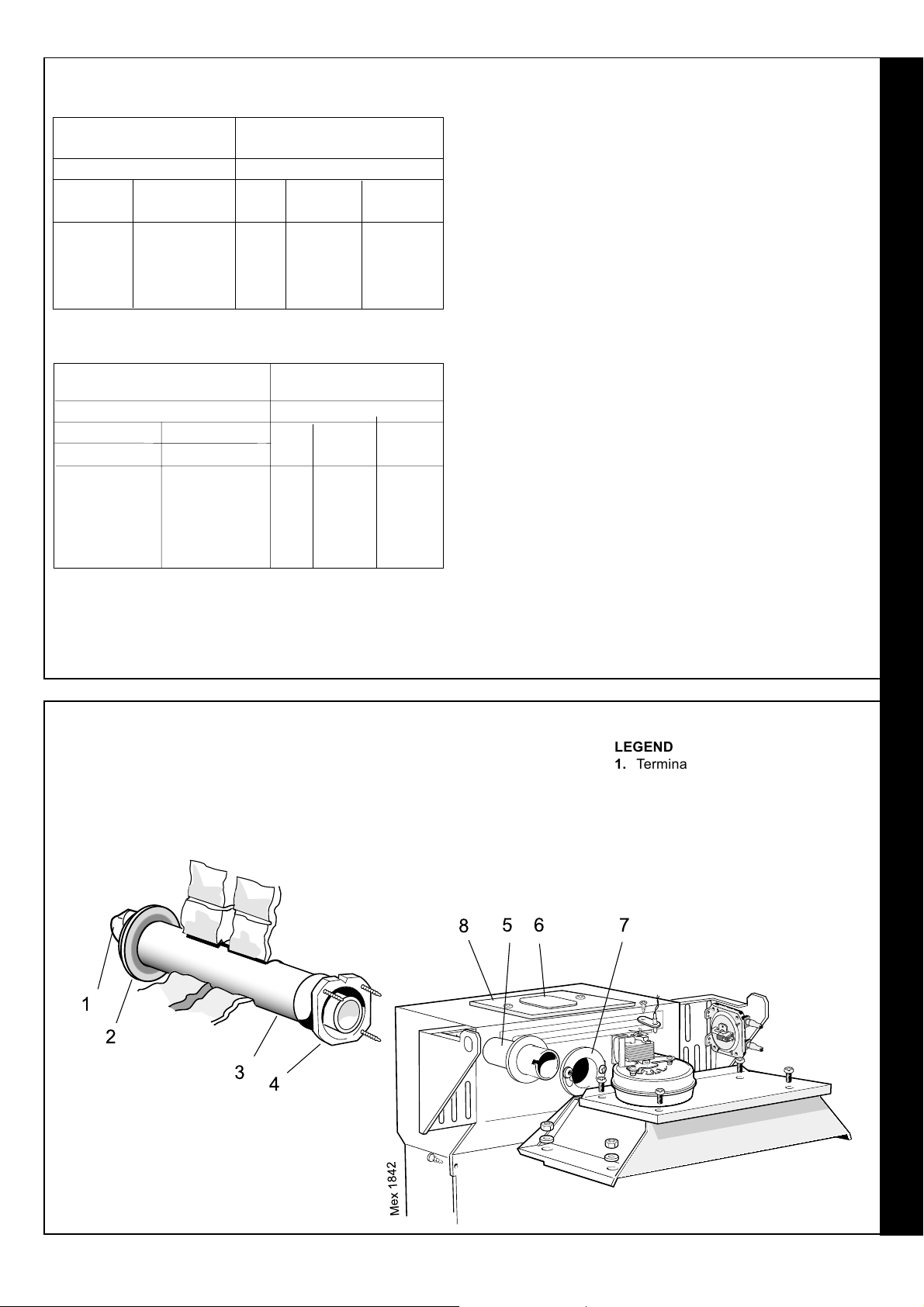
13
REAR FLUE ASSEMBLY - Exploded view
For wall thickness 114mm to 600mm
1. The boiler turret assembly is factory built for rear flue installation.
2. Remove the turret access cover.
3. Fit the flue extension tube (supplied with the boiler) to the flue connector,
rotate in the bayonet slot and secure with the M4 screws.
56 7
8
1
2
3
4
LEGEND
1. Terminal.
2. Weather seal.
3. Flue assembly.
4. Boiler sealing ring.
5. Flue extension tube.
6. Sealing plate.
7. Flue connector.
8. Turret access cover.
Mex 1842
British Gas 100 & 125 RD2 - Installation & Servicing
FLUE OUTLET
15
Page 16
INSTALLATION
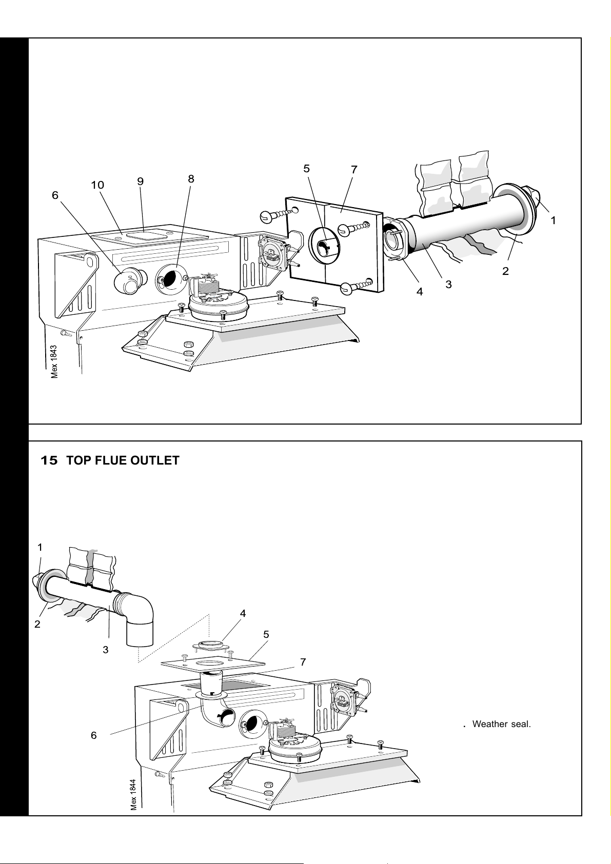
14
SIDE FLUE ASSEMBLY - Exploded view - For wall thickness 114mm to 600mm
Note. For lengths greater than 600mm see Frame 11.
1. The boiler turret assembly is factory built for rear flue
installation.
2. Remove the turret access cover.
3. Remove the sealing plate from the appropriate side to be
used and refit in the rear outlet.
10
9
8
6
4. Fit the outlet elbow pointing in the desired direction. Rotate
in the bayonet slot and secure with the M4 screw.
5. Fit the kit extension tube (with ring) to the flue elbow, rotate
in the bayonet slot and secure with the M4 screw.
6. When cutting the ducts always use the cardboard support
provided.
5
7
1
2
3
4
Mex 1843
LEGEND
1. Terminal.
2. Weather seal.
15
TOP FLUE OUTLET ASSEMBLY - 100 ONLY - Exploded view
IMPORTANT
The maximum total equivalent horizontal flue length is 2m for
100 model.
3. Flue assembly.
4. Boiler sealing ring.
5. Flue extension tube ( with ring).
1
4
2
5
3
6. Elbow.
7. Side outlet plate.
8. Flue connector.
Notes. For lengths greater than 600mm see Frame 11.
1. The boiler turret assembly is factory built for rear flue
installation.
2. Remove the turret access cover.
3. Remove the sealing plate from the turret access cover and
refit in the rear outlet.
4. Fit the outlet flue elbow pointing upwards, rotate in the
bayonet slot and secure with the M4 screw.
5. Fit the kit extension tube (with no ring) to the flue elbow,
rotate in the bayonet slot and secure with the M4 screw.
6. When cutting the ducts always use
the cardboard support provided.
9. Sealing plate.
10. Turret access cover.
7
6
FLUE OUTLET
16
LEGEND
1. Terminal.
2. Weather seal.
3. Flue assembly.
4. Boiler sealing ring.
5. Flue extension tube.
6. Elbow.
7. Flue connector.
8. Turret access cover.
Mex 1844
British Gas 100 & 125 RD2 - Installation & Servicing
Page 17

16
PREPARING THE WALL
1. Tape the template into the selected position.
2. Mark onto the wall the position of the flue
duct hole.
IMPORTANT. Ensure that, during the cutting
operation, masonry falling outside of the building
does not cause damage or personal injury.
3. Cut the flue hole, preferably with a 125mm
(5") core boring tool, ensuring that the hole is
square to the wall. If the hole has been quite
accurately cut with a drill then making good
the wall faces is not essential as seals are
provided at both ends of the flue. However,
both wall faces immediately around the cut
hole should be flat; make good if necessary.
For less accurate holes make good to
approximately 125mm (5") diameter at the 2
wall faces.
4. Remove the template from the wall.
INSTALLATION
Note.
If the terminal is to be
sited within 25-40mm
of a corner or vertical
pipe (refer to Table 3)
then the hole MUST
be accurately cut and
the rubber weather
seal trimmed around
the groove provided.
The terminal wall plate
need not be fitted.
17
CUTTING THE FLUE - wall thicknesses of 114 to 600mm
1. Measure and note the wall thickness X.
2. Mark the wall thickness onto the flue.
3. To ensure the tube is cut square, mark the flue all
the way round.
4. Cut to length X, using the cardboard ring for
support.
5. Remove cardboard ring and remove any burrs.
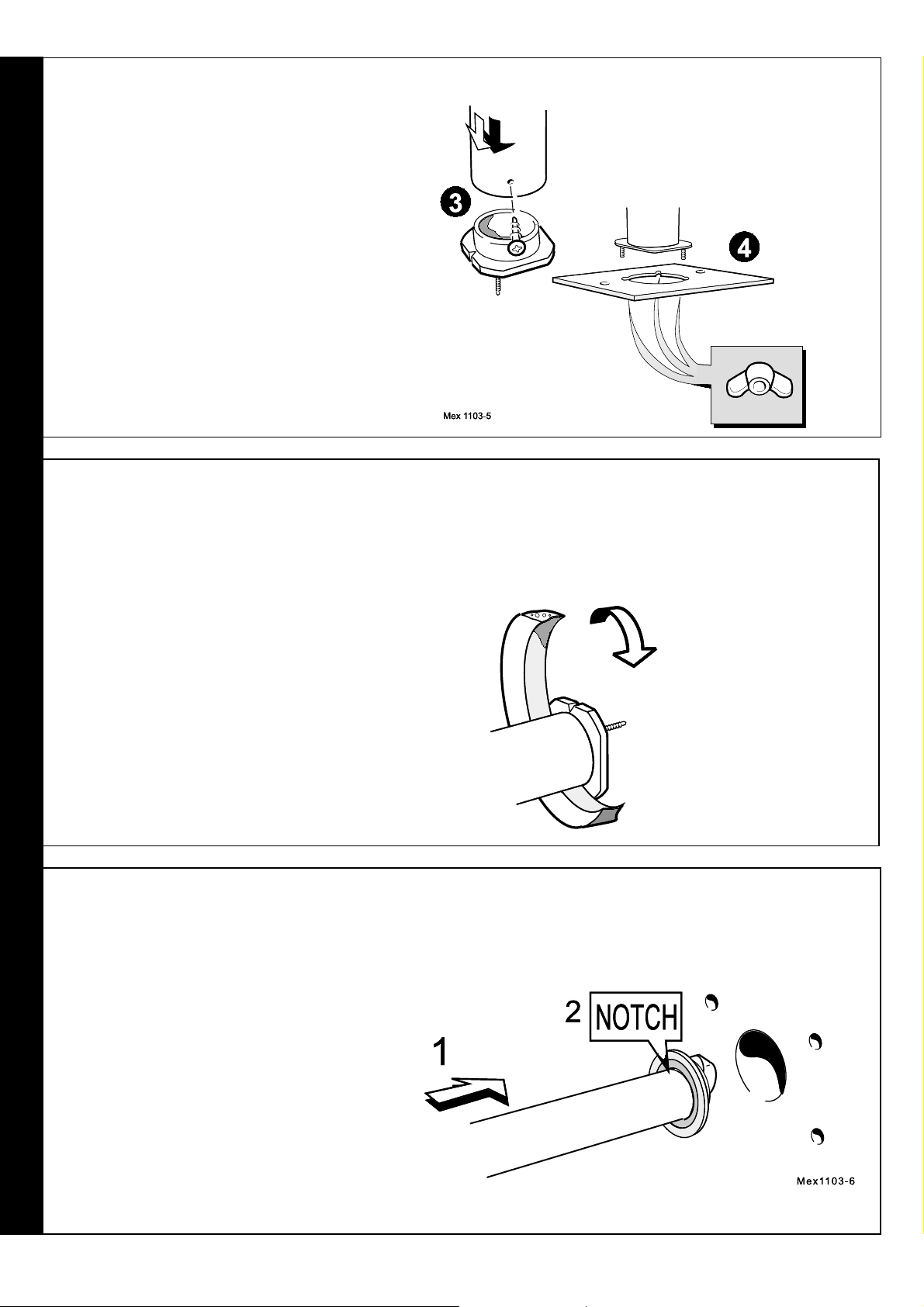
18
FITTING THE BOILER SEALING RING TO THE FLUE - Rear and Side
1. Fit the boiler sealing ring inside the outer flue duct. Ensure
the boiler sealing ring is fully engaged.
Ensure the notch aligns with the groove on the outer flue
duct. This ensures correct alignment of the flue terminal.
2. Drill 3 holes 3.2mm (
and boiler sealing ring.
1/8") dia. through the outer flue duct
Do NOT drill the inner flue
duct.
3. Insert the self-tapping screws, provided, in order to fix the
boiler sealing ring in position.
4. If the boiler is located with the rear against the wall, stick
the self adhesive foam strip, provided, onto the flue
immediately behind the boiler sealing ring. Otherwise refer
to Frame 20.
British Gas 100 & 125 RD2 - Installation & Servicing
FLUE OUTLET
17
Page 18
INSTALLATION
19
FITTING BOILER SEALING RING TO THE FLUE - Top (100 only)
1. Fit the boiler sealing ring inside the appropriate
length (A) of outer flue duct (refer to Frame 11).
Ensure the boiler sealing ring is fully engaged.
2. Drill 3 holes 3.2mm (
duct and boiler sealing ring.
flue duct.
3. Insert the self tapping screws, provided, in order to
fix the boiler sealing ring in position.
4. Fit the turret access cover to the sealing ring.
20
FITTING THE FOAM SEAL
1/8") dia. through the outer flue
Do not drill the inner
1. To determine the position for the foam seal
measure the wall thickness and mark it onto
the flue, measuring from the groove near the
terminal.
2. Wrap the self-adhesive foam strip round the
flue, ensuring that the foam is on the terminal
side of the line. This seals the gap between
the flue and the wall.
21
FITTING THE FLUE ASSEMBLY
A. Inside fitting.
If the flue assembly cannot be fitted from the outside,
proceed as follows:
1. Insert the flue assembly through the hole far enough to
allow the rubber seal to unfold completely and form
an adequate seal on the outside wall.
2. Ensure the notch is at the top. This will aid the
location of the studs into the boiler back panel.
3. Proceed to Frame 22, item B.
B. Outside fitting.
Proceed to Frame 22, item A.
FLUE OUTLET
18
British Gas 100 & 125 RD2 - Installation & Servicing
Page 19

INSTALLATION
22
LOCATING THE BOILER
Rear and Side flue
A. If the flue assembly can be fitted from the outside,
proceed as follows:
1. Move the boiler into position ensuring that the flue
outlet is in line with the wall opening.
2. Insert the flue assembly ensuring that the flue slides
into the flue extension and the 3 sealing ring studs
locate into the boiler.
23
CONNECTING THE FLUE TO THE BOILER - Rear
1. Secure the flue to the boiler
using the three M5 wing nuts
provided.
B. If the flue assembly has been fitted from the inside
proceed as follows:
1. Move the boiler into position ensuring that the flue
slides into the flue extension tube and the 3
sealing ring studs locate into the boiler back
panel.
Top flue
Position the boiler beneath the flue assembly.
Note.
The sealing ring studs will locate in
the back panel one way only. This
will ensure that the terminal is
correctly aligned.
24
CONNECTING THE FLUE TO THE BOILER - Side
1. Secure the flue to the boiler, using the
three M5 wing nuts provided.
2. Fit the kit extension tube (with ring) to the
flue elbow, rotate in the bayonet slot and
secure with the M4 screw.
3. Engage the extension tube into the flue
outlet, connect the elbow to the fan outlet
and secure with the M4 screw.
Note.
The sealing ring studs will locate in the back
panel one way only. This will ensure that the
terminal is correctly aligned.
British Gas 100 & 125 RD2 - Installation & Servicing
FLUE OUTLET
19
Page 20

INSTALLATION
25
CONNECTING THE FLUE TO THE BOILER - Top (100 only)
1. Connect the flue terminal to the boiler,
using the length (A) of flue duct
previously cut and ensuring that the
inner flue locates into the kit extension
tube (without ring).
2. Secure the flue to the boiler using the 2
M4 x 16mm screws previously
removed.
26
FITTING THE SIDE OUTLET PLATES
(Supplied in the Flue Directional Kit)
Note. If the boiler is fitted closer than 25mm to the side wall
the side outlet plate must be fitted now.
1. Split the side outlet plate into 2 down the split line.
2. Fit the 2 halves of the side outlet plate to the wall,
ensuring they are behind the boiler sealing ring.
FLUE OUTLET
20
British Gas 100 & 125 RD2 - Installation & Servicing
Page 21

2
7 FLUE EXTENSION DUCTS
SERVICING
INSTALLATION
28
FLUE EXTENSION DUCTS - continued
FLUE KITS
Pack B: supplied as standard.
Pack D: optional extension kit for side flue, top or rear flue outlet. Refer to Frame 27.
1. A maximum of 2 extension ducts (plus the standard flue duct) may be used together.
2. Flue extensions of greater than 1m (39") should be supported with the bracket
provided.
Flue length
Up to 600 B, 1 off B, 1 off 150 308
600 to 1000 B, 1 off + D, 1 off B, 1 off + D, 1 off 150 308+152132
600 to 1550 B, 1 off + D, 1 off N/A 150 308+
1550 to 2000 B, 1 off + D, 2 off N/A 150 308+
29
FITTING THE KIT
1. Remove the cardboard support aid from the flue and
place safely to one side.
mm
Top outlet flue length = A + B + Elbow allowance
o
Elbow = 1m
90
o
Elbow = 0.7m
45
100 Pack Req. 125 Pack Req. Product No.
152132, 1 off
152132, 2 off
2. Fit the inner flue extension duct onto the inner flue duct.
3. Fit the outer flue extension duct onto the outer air duct.
4. Drill 3 - 3.2mm (
Do not drill the inner flue duct.
5. Insert the self tapping screws provided to fix the air duct
in position.
6. Repeat steps 1-5 if a second flue extension is required.
1/8") dia. holes through the outer air duct.
British Gas 100 & 125 RD2 - Installation & Servicing
21
Page 22

30
TERMINAL WALL PLATE
This plate allows neat concealment and full compression of
the rubber seal. Its use is not essential if the flue hole and
flue ducts have been accurately cut and the outside wall
face is flat.
1. Position the terminal wall plate over the terminal.
2. Mark and drill 4 fixing holes with an 7mm (
drill.
3. Insert the 4 plastic plugs provided.
4. Secure the plate with 4 of the No.10 x 2" screws
provided.
9/32") masonry
INSTALLATION
Note. If the terminal is less than 2m (6' 6") above ground
level, an approved terminal guard should be fitted. Refer to
the Contents List on Page 4.
INSTALLATION
31
GAS CONNECTION
1. A MINIMUM working gas
pressure of 20 mbar (8
in.w.g.) MUST be available
at the boiler inlet, with the
boiler operating.
2. Extend a gas supply pipe
NOT LESS THAN 15mm
1/2") OD to the boiler and
(
connect to the gas cock
situated at the front LH side
of the boiler.
3. Test the gas installation for
soundness and purge in
accordance with BS.6891:
1988. Refer to Servicing
instructions.
Boiler Dimension A
100 473 (18
125 546 (21
5/8")
1/2")
32
WATER CONNECTIONS
1. Connect the system flow and return pipework to the
boiler as appropriate. Refer to Frames 3,4, 5 and 6 for
guidance on system design.
Notes.
Pumped flow and return pipes MUST be 28mm.
Gravity connections MUST be 28mm (1").
22
2. Ensure that all valves are open. Fill and vent the system
and check for water soundness.
Notes.
a. Isolating valves must be fitted as close to the pump
as possible.
b. The boiler is not suitable for use with a direct hot
water cylinder.
British Gas 100 & 125 RD2 - Installation & Servicing
Page 23

INSTALLATION
33
ELECTRICAL CONNECTIONS
WARNING. The appliance must be efficiently earthed.
A mains supply of 230 V ~ 50 Hz is required.
All external controls and wiring must be suitable for mains
voltage. Wiring should be in 3-core PVC insulated &
sheathed cable, not less than 0.75mm
2
(24 x 0.2mm) to BS.
6500 Table 16 Wiring Regulations and local regulations.
Connection must be made in a way that allows complete
isolation of the electrical supply - such as a double pole
switch, having a 3mm (1/8") contact separation in both poles,
serving only the boiler and system controls. The point of
connection to the mains should be readily accessible and
clearly marked.
1. Remove the securing screw and lift off the mains terminal
box cover.
2. Route the mains cable from the LH rear of the boiler, along
the front of the baseplate to the terminal box.
Note. Leave sufficient length of cable to enable it to be routed
as shown once the casing has been refitted and secure to
the casing with the ties provided.
3. Connect the live, earth & neutral wires into the terminal strip.
4. Secure the mains lead with the cable clamp.
5. Refit the terminal box cover.
IMPORTANT.
Control switching must not take place in this mains permanent
supply.
INSTALLATION
Notes.
1. If the optional
Programmer Kit is
to be fitted refer to
the instructions
provided with the
kit and Frame 35.
2. For gravity DHW
applications the
pump MUST be
wired through the
programmer.
34
FLOW WIRING DIAGRAM
LEGEND
b blue
bk black
br brown
r red
y yellow
w white
gy grey
or orange
v violet
pk pink
g/y green/yellow
Volt Free Contacts
If switched live is connected here (EC1) leave other terminal without
connection. If programmer is used here (EC1) the switched live MUST
Detection
O/heat thermostat
Reset
EC2
EC1
Gas valve
Fan
com
NC
BE FUSED AT 2A MAXIMUM.
Air pressure switch
Mex 1847
v
v
NO
HSI
Return
sensor
r
r
b
b
Flow
sensor
r
r
gy
gy
Flue
sensor
Link
or
or
pk
r
b
br
gy
gy
r
y
v
Fuse
L
N
br
b
N
L
Mains
LED 4
LED 3
Modem
Boiler control
potentiometer
LED 2
LED 1
v
r
pk
All EARTHS must be connected
(Not all earths are shown for clarity)
British Gas 100 & 125 RD2 - Installation & Servicing
23
Page 24

SERVICING
35
EXTERNAL CONTROLS
The wiring diagrams illustrated in Frames 35-37 cover the
systems most likely to be fitted to this appliance.
For wiring external controls to the British Gas RD2 boiler,
reference should be made to the system wiring diagrams
supplied by the relevant manufacturer, in conjunction with the
wiring diagrams shown in Frame 31.
Difficulty in wiring should not arise, providing the following
directions are observed:
1. Preferred Wiring Method.
Controls that switch the system on or off, e.g. a time
switch, must be wired, in series and terminate with a volt
free contact across EC1/EC2.
2. Alternative Wiring Method. A switched live supply may be
connected to EC1 (leaving EC2 without connection), which
INSTALLATION
MUST BE fused at 2A MAXIMUM.
IMPORTANT.
A link wire between terminal EC1and EC2 is not acceptable.
Note. Route the cable to terminals EC1 & EC2 from the RH
rear of the boiler and across the top of the control box.
Refer to Frame 31. Leave sufficient length of cable to
enable it to be routed as shown once the casing has been
fitted and secure to the casing with the ties provided.
4. Controls that override an on/off control, e.g. frost
thermostat must be wired, in parallel, with the control(s) to
be overridden. Refer to Frame 38.
5. If a proprietary system is used, follow the instructions
supplied by the manufacturer.
Advice on required modifications to the wiring may be
obtained from the component manufacturers.
Notes.
1. Connection between a frost thermostat and the time
control should be made without disturbing other wiring.
2. A frost thermostat should be sited in a cool place in the
house, but where it can sense heat from the system.
36
PICTORIAL WIRING
Note 1.
Volt Free contacts
If switched live is connected here
(EC1) leave other terminal without
connection. If programmer is used
here (EC1) and the switched live
MUST BE FUSED at 2 A Max.
LEGEND
w white
r red
bk black
br brown
pk pink
b blue
gy grey
v violet
y/g yellow/green
Fan
Hot surface igniter
Detection
electrode
Burner On
neon
w
w
b
gy
gy
Reset button
br
Alternative Wiring Method.Preferred Wiring Method.
Fan
sensor
r
r
or
or
b
y/g
br
gy
gy
Mex 1312
Air pressure switch
Flow sensor
Return sensor
O/heat 'stat
v
v
NO
com
NC
pk
Control box
earth screw
b
br
r
Fuse
b
b
LED 4
LED 3
LED 2
LED 1
r
r
Read
note1.
br
b
y/g
MAINS SUPPLY
Modem
v
r
pk
v
r
pk
Boiler control
potentiometer
24
British Gas 100 & 125 RD2 - Installation & Servicing
Page 25

SERVICING
37
MID POSITION VALVE
Pumped only
Notes.
1. Some earth wires are omitted for clarity. Ensure proper
earth continuity when wiring.
2. For numbering of terminals on thermostats see the
manufacturer's literature.
3. This is a fully controlled system - set the boiler
thermostat to maximum.
4. 'Switchmaster ' (Smiths) valves are similar but the wiring
is different. Consult the diagram supplied with the valve.
INSTALLATION
LEGEND
b blue
bk black
38
TWO SPRING CLOSED VALVES
Pumped only
Notes.
1. Some earth wires are omitted for clarity. Ensure proper
earth continuity when wiring.
2. For numbering of terminals on thermostats see the
manufacturer's literature.
3. This is a fully controlled system - set the boiler
thermostat to maximum.
4. 'Switchmaster' (Smiths) valves are similar but note that
the GREY (NOT the orange) wire MUST be the one
connected to permanent L.
LEGEND
b blue
bk black
br brown
r red
or orange
br brown
r red
w white
w white
gy grey
y/g yellow/green
or orange
y/g yellow/green
gy grey
39
HONEYWELL 'C' PLAN
Gravity HW & Pumped CH
IMPORTANT
The pump must not be wired directly to the boiler.
Notes.
1. Some earth wires are omitted for clarity. Ensure proper
earth continuity when wiring
2. For numbering of terminals on thermostats see the
manufacturer's literature.
LEGEND
w white
r red
bk black
br brown
or orange
b blue
gy grey
y/g yellow/green
British Gas 100 & 125 RD2 - Installation & Servicing
25
Page 26

40
FROST PROTECTION
Central heating systems fitted wholly inside the house
do not normally require frost protection as the house
acts as a 'storage heater' and can normally be left at
least 24 hrs. without frost damage. However, if parts of
the pipework run outside the house or if the boiler will be
left off for more than a day or so then a frost 'stat should
be wired into the system.
This is usually done at the programmer, in which case
the programme selector switches are set to OFF and all
other controls MUST be left in the running position.
The frost 'stat should be sited in a cold place but where
it can sense heat from the system.
Wiring should be as shown, with minimal disturbance to
INSTALLATION
other wiring of the programmer.
Designation of the terminals will vary, but the
programmer and thermostat manufacturer's leaflets will
give full details.
Diagram A shows a double pole frost thermostat, which
should suffice for all systems which do not use the OFF
SERVICING
Clock with volt free contacts should be used.
terminals of the programmer.
Diagram B shows a 'change-over' frost thermostat, which will cover
most systems which do use CH OFF. If, however, on such a system
the HW pipework is in an isolated part of the house, a second frost
thermostat may be used to protect it.
If in doubt, ask your installer for advice.
41
FITTING THE CASING & CONTROL SENSORS
1. Offer up the RH side panel, locating it with the peg in the
baseplate, and push the panel back engaging it into the
collector hood tab.
2. Secure the panel to the baseplate and turret front panel.
3. Repeat steps 1 and 2 to refit the LH side panel.
4. Refit the control box by locating it on the peg under the RH
side and securing with the M5 screw at the LH side.
5. Insert the flow temperature sensor (red lead) to the full
depth of the pocket and secure the retaining plate with the
screw provided.
6. Insert the return temperature sensor (blue lead) to the full
depth of the pocket and secure with the Heyco bush
provided.
7. Carefully uncoil the overheat thermostat capillary wihtout
kinking it andfit the sensor into the overheat thermostat
pocket, securing it with the hook plate and screw as shown.
Route the capillary clear of the combustion chamber.
8. Ensure that the reset button on the overheat thermostat is
pressed in.
9. Place the top panel and push back.
10. Secure the panel to the side panels.
11. Refit the control panel using the screws previously removed.
12. Relocate the 'Burner on' neon in the lens holder at the back of the
13. Fit the control thermostat to the rear of the control
14. Fit the control thermostat knob.
15. Secure the wiring harnesses in the edge clips on
16. Secure all other internal wiring.
IMPORTANT. Wiring within the boiler casing must be neatly secured
with the cable straps provided and MUST NOT be allowed to touch the
fan cooling impellor, the burner front plate, or the cleanout cover and
the collector hood.
17. Refit the grille assembly.
Mex 1850
Thermostat
pocket
5
Hook plate
6
7
Sensor end
control panel.
panel using the 2 screws provided. Fit the correct
way up as shown (T).
the RH side panel..
26
British Gas 100 & 125 RD2 - Installation & Servicing
Page 27

42
COMMISSIONING AND TESTING
A. ELECTRICAL INSTALLATION
1. Checks to ensure electrical safety should be carried
out by a competent person.
2. ALWAYS carry out preliminary electrical system
checks, i.e. earth continuity, polarity, resistance to
earth and short circuit using a suitable test meter.
WARNING. Whilst effecting the required gas soundness test and purging air from the gas installation,
open all windows and doors, extinguish naked lights and DO NOT SMOKE.
SERVICING
B. GAS INSTALLATION
1. The whole of the gas installation, including the meter,
MUST be inspected and tested for soundness, and purged
in accordance with the recommendations of BS. 6891.
2. Purging air from the gas installation may be expedited by
loosening the union on the gas service cock on the boiler
and purging until gas is detected.
3. Retighten the union and check for gas soundness.
43
INITIAL LIGHTING
INSTALLATION
LEGEND
A. Gas control valve.
B. Burner pressure test point.
C. Main burner pressure
adjuster.
D. Inlet pressure test point.
E. Gas service cock.
F. Boiler thermostat knob.
G. 'Burner 'On' neon.
H. Overheat thermostat reset
button.
J. Lock out reset button.
TO LIGHT THE BOILER
1. Check that all the drain cocks are closed and any valves in
the flow and return are open.
2. Check that the gas service cock [E] is OPEN and the boiler
thermostat [F] is OFF.
3. Slacken the screw in the burner pressure test point [B] and
connect a gas pressure gauge via a flexible tube.
4. Switch the electricity supply ON and check that all external
controls are calling for heat.
5. Press the reset button (J) and the overheat thermostat reset
button (H).
6. Set the boiler thermostat knob [F] to position 6. The fan will
start. After the fan has run for a few seconds the igniter will
be energised. The gas valve will open and the main burner
will then cross-light smoothly. The boiler may attempt 5
ignitions. If this fails, the boiler requires to be manually reset
by pressing the reset button. If this sequence does not occur,
refer to the Fault Finding section.
British Gas 100 & 125 RD2 - Installation & Servicing
7. Test for gas soundness around ALL boiler gas components
using leak detection fluid.
8. Operate the boiler for 10 minutes to stabilise the burner
temperature.
9. The boiler is preset at the factory to its nominal rating. If
adjustment is necessary remove the sealing cap and turn
the adjusting screw [C] clockwise to increase/anticlockwise
to decrease the pressure until the required burner pressure
is achieved.
Refit the sealing cap.
10. Set the boiler thermostat to (F) OFF.
11. Remove the pressure gauge and tube. Retighten the sealing
screw in the pressure test point.
12. Turn ON and check for gas soundness at the pressure test
point.
13. Refit the lower front panel and secure with the 2 fixing screws.
14. Finally stick the appropriate British/Scottish Gas logo
(supplied) in the marked area at the top LH corner of the
controls panels door.
27
Page 28
44
GENERAL CHECKS
SERVICING
Make the following checks for correct operation:
1. Turn the boiler thermostat OFF and ON to check that the
main burner is extinguished and relit in response.
2. Set the boiler thermostat knob to position 6 and operate
the mains on/off switch. Check that the main burner lights
and extinguishes in response.
3. Check that the programmer, if fitted, and all other system
controls function correctly.
Operate each control separately and check that the main
burner or circulating pump (as the case may be)
responds.
INSTALLATION
4. Water circulation System
a. With the system HOT, examine all water connections
for soundness.
b. With the system still hot, turn off the gas, water and
electricity supplies to the boiler and drain down, in
order to complete the flushing process.
c. Refill and vent the system, clear all air locks and again
check for water soundness.
d. Balance the system.
5. Finally, set the controls to the user's requirements and
close the controls door.
Thermostat Flow Temperature
Knob Setting
2 60 140
3 66 150
4 71 160
5 77 170
6 82 180
Notes.
zz
z If an optional programmer kit is fitted refer to the
zz
separate Programmer Kit Installation Instructions
and Programmer Kit User's Instructions.
zz
z The temperatures quoted below are approximate
zz
and vary between installations.
o
C
o
F
WARNING. The boiler must not be operated with the casing removed.
45
HANDING OVER
After completing the installation and commissioning of the system the
installer should hand over to the householder by the following actions:
1. Hand the User's Instructions to the householder and
explain his or her responsibilities under the current Gas
Safety (Installation and Use) Regulations or the rules in
force.
2. Draw attention to the lighting instruction label affixed to the
inside of the controls door.
3. Explain and demonstrate the lighting and shutting down
procedures.
4. The operation of the boiler and the use and adjustment of
ALL system controls should be fully explained to the
householder, to ensure the greatest possible fuel economy
consistent with household requirements of both heating and
hot water consumption.
6. Explain the function of the boiler overheat thermostat and
emphasise that if cutout persists, the boiler should be
turned off and a CORGI registered installer consulted.
7. Explain and demonstrate the function of time and
temperature controls, radiator valves etc., for the
economic use of the system.
8. If any programmer is fitted then draw attention to the
programmer User's Instructions and hand them to the
householder.
After installation, commissioning and customer
hand-over, please complete the
appliance log book and leave this with the customer.
Advise the User of the precautions necessary to prevent
damage to the system and to the building in the event of
the system remaining inoperative during frosty conditions.
5. Explain the function and the use of the boiler thermostat
and external controls.
28
9. Stress the importance of regular servicing by a CORGI
registered installer and that a comprehensive service
should be carried out AT LEAST ONCE A YEAR.
10. As the installer you may wish to undertake the service
contract yourself or alternatively offer to the customer the
benefits of the British Gas Services, details of which are
outlined in the household pack supplied with this boiler.
British Gas 100 & 125 RD2 - Installation & Servicing
Page 29

SERVICING
46
SCHEDULE
WARNING.
BEFORE SERVICING always turn OFF the gas supply at the
gas service cock and switch OFF and DISCONNECT the
electrical supply to the appliance.
To ensure the continued safe and efficient operation of the
appliance it is recommended that it is checked at regular
intervals and serviced as necessary. The frequency of
servicing will depend upon the installation condition and usage
but should be carried out at least annually .
It is the law that any service work must be carried out by a
CORGI registered instatller.
a. Light the boiler and carry out a pre-service check, noting any
operational faults.
b. Operate the boiler for at least 20 minutes. Check the gas
consumption.
c. Connect a suitable gas analyser to the sampling point on the
flue collector. Refer to Frame 50.
For correct operation the CO/CO
should not be greater than 0.004 ratio. If this is the case and
the gas input is within 95% of the nominal then no further
action need be taken. If not the case, proceed to step (d)
content of the flue gas
2
d. Clean the main burner. Refer to Frame 49.
e. Clean the heat exchanger. Refer to Frame 50.
f. Clean the main injectors. Refer to Frame 49.
g. Check that the flue terminal is unobstructed and that the
flue system is sealed correctly.
h. If the appliance has been installed in a compartment, check
that the ventilation areas are clear.
The servicing procedures are covered more fully in Frames
47 to 52 and MUST be carried out in sequence.
Note.
In order to carry out either servicing or replacement of
some components, the boiler casing must removed. Refer
to Frame 47.
IMPORTANT. After completing the servicing or exchange of
components always test for gas soundness and carry out
functional checks as appropriate.
When the work is complete the casing MUST be correctly
refitted and secured.
The boiler must NOT be operated if the casing is not fitted.
47
BOILER CASING REMOVAL
1. Remove the 2 screws and lift off the lower front panel.
2. Remove the 2 screws and lift off the grille assembly.
3. Disconnect the electrical leads from the gas valve.
4. Release the 'Burner On' neon from the lens holder at
the rear of the control panel.
5. Disconnect the thermostat from the
control panel:
a. Pull off the thermostat knob.
b. Undo the 2 securing screws and
withdraw the thermostat from the
panel.
6. Remove the 2 screws securing the
control panel and pull down to release
the tabs from under the top panel.
7. If the boiler is not fitted under a work
top, access for flue cleaning will be
improved by removing the top panel:
a. Remove the 2 securing screws.
b. Pull the panel forward and lift off.
British Gas 100 & 125 RD2 - Installation & Servicing
29
Page 30

SERVICING
48
BURNER AND CONTROLS ASSEMBLY REMOVAL
1. Remove the control box cover.
2. Unplug the HSI lead from the PCB and withdraw it
from the box.
3. Disconnect the detection lead from the electrode.
4. Remove the screw securing the control box to the
baseplate, slide to the left to release and place to
one side.
5. Undo the gas service cock union.
6. Remove the 4 wing nuts and withdraw the burner
and controls assembly, complete, from the boiler.
7. Place on a convenient working surface.
49
CLEANING THE BURNER ASSEMBLY
Note. Brushes with metallic bristles MUST NOT be used.
1. Brush off any deposits that may have fallen onto the
burner heads (ensuring that the flame ports are
unobstructed) and remove any debris that may have
collected.
2. Remove the main burner injectors .Check, clean or
replace, as required.
3. Refit the injectors, using an approved jointing
compound.
4. Inspect the ignition/detection electrodes; ensure they
SERVICING
are clear and in good condition.
50
CLEANING THE FAN/FLUEWAYS
1. Remove the silicon rubber tube from the fan pressure
sensing point.
2. Disconnect the fan leads.
3. Remove the screw and withdraw the fan thermistor sensor
from the scroll.
4. Disconnect the silicon rubber tube from the top of the
collector hood.
5. Remove the 4 M4 screws on the top of the collector hood
and by sliding it forwards remove collector hood/fan
assembly.
6. Check that the fan impellor runs freely. Remove any
debris from the impellor with a soft brush.
7. Remove the flue baffles.
8. Remove all loose deposits from the heat exchanger,
particularly between the fins, using a suitable brush.
9. Re-assemble in reverse order. Lubricate fan 'O' ring with
silicon grease. Ensure the fan leads, 2 sensing tubes and
fan sensor are reconnected.
Check that:
a. The HSI and detection electrodes are clean and
undamaged.
b. The HSI and detection leads are in good condition.
c. The position of the HSI and detection electrodes
relative to the burner are correct. Refer to Frame 54 &
57.
5. Clean or renew components as necessary.
30
British Gas 100 & 125 RD2 - Installation & Servicing
Page 31

SERVICING
51
RE-ASSEMBLY
Re-assemble the boiler in the following order:
1. Refit the flue baffles.
2. Inspect the collector hood rope gasket and replace, if
necessary, ensuring that the self adhesive rope is fitted
centrally on to the lip of the collector hood / fan assembly.
The boiler efficiency will be adversely affected if incorrectly
fitted. Refit the collector hood cover with the 4 screws.
Tighten the screws. Ensure that the sealing gasket is
compressed. Refit the pressure pipe.
3. Refit the positive pressure tubes on the top of the fan
housing. Reconnect the electrical leads.
52
GAS PRESSURE ADJUSTMENT
4. Refit the thermistor sensor and secure with the M4
screw.
5. Refit the burner assembly.
6. Reconnect the gas supply and the electrical wiring.
7. Refit the control box.
8. Check for gas soundness. Check the gas service
cock and pressure test point.
9. Refit the boiler top panel, control panel and grille
assembly.
Main Burner Pressure
After servicing, reference should be made to Table
1, which quotes details of the rated output with the
related burner pressure and heat input. Any
REPLACEMENT OF PARTS
53
GENERAL
When replacing any component:
1. Isolate the electricity supply.
2. Turn OFF the gas supply.
3. Remove the lower front panel and grille
assembly. Refer to Frame 47.
The boiler MUST NOT be operated if the casing is not fitted.
required adjustments should be made using the
pressure adjustment screw. Refer to Frame 41- Initial
Lighting.
Refit the lower front panel and secure with the 2 fixing
screws.
IMPORTANT.
The original routing of wires must be adhered to when
replacing the electrical components.
SERVICING
British Gas 100 & 125 RD2 - Installation & Servicing
31
Page 32

SERVICING
54
HOT SURFACE IGNITER (HSI) REPLACEMENT
1. Remove the lower front panel and grille
assembly. Refer to Frame 47.
2. Remove the securing screw and lift off
the control box cover.
3. Unplug the HSI lead from the PCB and
withdraw it from the control box.
4. Remove the securing screw and
withdraw the HSI from the burner front
plate.
5. Fit the new HSI and reassemble in
reverse order.
6. Check that the position of the HSI
relative to the burner is correct.
7. Check the operation of the boiler.
55
SERVICING
CONTROL THERMOSTAT POTENTIOMETER REPLACEMENT
1. Remove the lower front panel
and grille assembly. Refer to
Frame 47.
2. Remove the control box
cover.
3. Unplug the potentiometer
lead from the PCB and
withdraw it from the control
box.
4. Disengage the lead from the
retaining clips
5. Pull off the thermostat knob.
6. Remove the 2 screws
securing the potentiometer to
the control panel.
7. Remove the backnut securing
the potentiometer to the
bracket.
8. Fit the new potentiometer and
reassemble in reverse order.
9. Check the operation of the
boiler.
32
British Gas 100 & 125 RD2 - Installation & Servicing
Page 33

SERVICING
56
CONTROLS PANEL REPLACEMENT
1. Remove the lower front panel/grille assembly and control
panel. Refer to Frame 47.
2. Remove the control thermostat potentiometer. Refer to
Frame 55.
3. Unclip the 'Burner On' neon from the lens holder.
57
FLAME DETECTION ELECTRODE AND LEAD REPLACEMENT
4. Fit the new control panel and re-assemble in reverse
order.
5. Check the operation of the boiler.
1. Remove the lower front panel/grille assembly. Refer to
Frame 47.
2. Remove the burner and controls assembly.
a. Remove the control box cover.
b. Unplug the HSI lead from the PCB and withdraw it from
the box.
c. Disconnect the detection lead from the electrode.
d. Remove the screw securing the control box to the
baseplate, slide to the left to release and place to one
side.
e. Disconnect the electrical leads from the gas valve.
f. Undo the gas service cock union.
g. Remove the 4 wing nuts and withdraw the burner and
controls assembly, complete, from the boiler
3. Remove the detection electrode retaining nut and
withdraw the electrode from the front plate.
4. Fit the new electrode and reassemble in reverse order.
5. Check that the position of the electrode relative to the
burner is correct.
6. Check the operation of the boiler.
SERVICING
British Gas 100 & 125 RD2 - Installation & Servicing
33
Page 34

58
MAIN BURNER REPLACEMENT
NOTES
1. Remove the lower
front panel/grille
assembly. Refer to
Frame 47.
2. Remove the burner
and controls assembly.
Refer to Frame 57.
3. Remove the 2 nuts
and washers securing
the burner to the front
plate and manifold.
Withdraw the burner.
4. Fit the new burner and
re-assemble in reverse
order, taking care not
to damage the main
burner injector which
is screwed into the
burner manifold.
5. Check the operation of
the boiler.
59
MAIN BURNER INJECTOR REPLACEMENT
1. Remove the lower front panel/grille
SERVICING
assembly. Refer to Frame 47.
2. Remove the burner and controls assembly.
Refer to Frame 57.
3. Undo the manifold securing nuts and remove
the manifold from the front plate.
4. Unscrew the burner injector from the
manifold.
5. Fit the new injector, using an approved
jointing compound, and re-assemble in
reverse order.
6. Check the operation of the boiler.
34
British Gas 100 & 125 RD2 - Installation & Servicing
Page 35

60
GAS VALVE REPLACEMENT
1. Remove the lower front panel and grille
assembly. Refer to Frame 47.
2. Remove the burner and controls
assembly. Refer to Frame 57.
3. Unscrew the gas inlet pipe from the valve.
4. Remove the 4 securing screws and
withdraw the valve from the burner
manifold.
5. Fit the new gas valve, ensuring that:
a. The valve is fitted the correct way round
- an arrow engraved on the valve
indicates the direction of flow.
b. The sealing 'O' ring supplied with the
valve is correctly fitted at the outlet
flange.
c. An approved jointing compound is used
when reconnecting the gas inlet pipe.
6. Reassemble in reverse order.
7. Check the operation of the boiler.
NOTES
61
FAN REPLACEMENT
1. Remove the lower front panel, control panel and top panel. Refer to
Frame 47.
2. Remove the silicon rubber tube from the fan pressure sensing point.
3. Disconnect the fan leads.
4. Remove the securing screw and withdraw the fan thermistor sensor
from the scroll.
5. Disconnect the silicon rubber tube from the top of the collector hood.
6. Remove the 4 M4 screws on the top of
the collector hood and by sliding it
forwards remove collector hood / fan
assembly.
7. Remove the three M4 screws retaining
the fan to the collector hood.
8. Fit the new fan and re-assemble in
reverse order. Lubricate fan 'O' ring
with silicon grease. Ensure the fan
leads, 2 sensing tubes and fan sensor
are reconnected.
9. Check the operation of the boiler.
62
AIR PRESSURE SWITCH (APS) REPLACEMENT
SERVICING
1. Remove the lower front panel, control panel and
the top panel. Refer to Frame 47.
2. Remove the APS fixing screw.
3. Remove both sensing tubes from the APS.
4. Remove the 3 electrical connections from the
APS.
5. Fit the new APS and reassemble in reverse order.
6. Check the operation of the boiler .
British Gas 100 & 125 RD2 - Installation & Servicing
35
Page 36

GENERAL
PRINTED CIRCUIT BOARD (PCB) REPLACEMENT
63
IMPORTANT.
Any failure indicating a PCB fault should be confirmed
before replacing the PCB by ensuring that all
electrical connections are correctly made (Check pin
alignment) and secure.
1. Remove the lower front panel and grille assembly.
Refer to Frame 47.
2. Remove the control box cover.
3. Disconnect the detection electrode lead from the
PCB.
4. Unplug all Molex connectors from the PCB.
5. Disengage the PCB from the stand-offs to release
and remove it from the box.
6. Fit the new PCB and re-assemble in reverse order.
7. Check the operation of the boiler.
Overheat thermostat
reset button
Reset button
PCB
Fuse.
To change the fuse, prise the top off the holder and
disengage the fuse. Refer to Frame 34 for location.
64
THERMISTOR SENSOR LEAD HARNESS REPLACEMENT
1. Remove the lower front panel and grille assembly. Refer to Frame 47.
2. Remove the control box cover. Refer to Frame 63.
SERVICING
3. Unplug the 7-way Molex connector (carrying 6 wires) from the top of the
PCB.
4. Withdraw the leads from the control box and disengage them from the
retaining clips.
5. Remove the retaining screw and withdraw the flow thermistor sensor
from its pocket.
6. Compress the Heyco bush and withdraw the return thermistor sensor
from its pocket.
7. Remove the securing screw and withdraw the fan thermistor sensor from
the fan scroll.
8. Withdraw the complete harness from the boiler.
9. Fit the new harness and reassemble in reverse order.
10. Check the operation of the boiler.
Mex 1860
Control box cover
36
British Gas 100 & 125 RD2 - Installation & Servicing
Page 37

GENERAL
65
THERMOSTAT REPLACEMENT
1. Remove the lower front panel and grille assembly. Refer
to Frame47
2. Undo the overheat thermostat sensor retaining screw and
withdraw the sensor from the pocket.
3. Remove the control box cover.
4. Unfasten the overheat thermostat retaining nut ,
disconnect the electrical leads and withdraw the
thermostat from the control box.
5. Fit the new thermostat and reassemble in reverse order.
6. Check that the reset button on the new thermostat is
pressed in.
7. Check the operation of boiler.
6
Thermostat
pocket
Mex 1861
4
Hook plate
2
Sensor end
Mex 1862
Alignment peg
SERVICING
3
British Gas 100 & 125 RD2 - Installation & Servicing
37
Page 38

FAULT FINDING
Before attempting any electrical fault finding ALWAYS carry out
preliminary electrical system checks, i.e. earth continuity,
polarity and resistance to earth using a suitable meter.
START
Check the mains supply to the
terminal block and that there is a
demand for heat. Expect 230 V
AC. Press the lockout reset switch.
NO
Check mains supply and fuses.
Check programmer and system
thermostats are all ON. Check that
boiler plug and socket are OK and
fully connected.
YES
Is there a live supply on the overheat
'stat? Expect 230 V AC.
NO
Can the overheat 'stat
be reset when the
system is cold ?
YES
Check that the boiler thermostat is
set at maximum and LED 4 is ON.
Is the fan turning ?
YES
Is there a supply on the fan
NO
connector at PCB .
NO
Has the fuse blown on PCB ?
Refer to Frame 34.
YES
YES
Is there a
supply at the
fan ? Expect
230 V AC.
NO
Change fan
Rectify bad connection
Detailed instructions on the cleaning and adjustment or
replacement of faulty components are contained in the
'Servicing' section of this publication.
Reset the overheat 'stat. Set control
'stat to maximum. Allow the boiler to
reach temperature - if the overheat
'stat trips again, measure flow
temperature.
If above 90°C replace control 'stat.
YES
If below 90°C replace overheat 'stat.
NO
Replace the overheat thermostat.
Replace board BUT, before
attempting to start boiler,
check for short between live
YES
NO
and neutral, also between live
and earth, on all items
plugged into PCB.
Check all connections to PCB are
correctly made and secure.
If no error found, replace PCB.
Is the hot surface igniter glowing?
NO
Change igniter. Does
igniter work?
NO
YES
Does the main burner light ?
NO
Is there a gas supply
to the boiler?
YES
Is the pilot injector
blocked?
NO
Is there a supply voltage
at the gas valve?
Expect 230 V AC.
YES
Replace
gas valve
Component LED 3* LED 4*
Application of power. Flash > 1/sec in sync with LED 4 Flash > 1/sec in sync with LED 3
Control 'stat open circuit or On. On.
waiting for demand.
Fan start up. Off. Flash > 1/sec
Run. Off. On.
Pump over-run. On Off.
Lock-out. Flash < 1/second. Off.
Sensor Faults Flash > 1/second. Off.
Reverse polarity. Flash > 1/sec alternately with LED 4. Flash > 1/sec alternately with LED 3.
FAULT FINDING FAULT FINDING FAULT FINDING FAULT FINDING FAULT FINDING FAULT FINDING
* Refer to Frame 36
NO
YES
Does the hot
surface
igniter turn
off?
NO
Check all
connections to
PCB are
correctly made
and secure.
If no fault found,
replace PCB
YES
Does main burner
cross-light from pilot?
NO
Is there a supply on terminals of
main gas valve? Expect 230 V AC.
NO
Is the main burner
injector clear?
YES
YES
Replace main gas
solenoid valve
Check pressure switch sensing
pipes for blockages, bad
connections and reversed
connection.
Is pressure difference at switch
greater than 0.9 mbar?
YES
Change pressure
switch. Is fault
corrected?
NO
Check all connections to PCB are
correctly made and secure.
If no fault found change PCB.
NO
Change fan.
Is fault
corrected?
NO
38
British Gas 100 & 125 RD2 - Installation & Servicing
Page 39

SHORT LIST OF PARTS
The following are parts commonly required as replacement
components, due to damage or expendability. Their failure or
absence is likely to affect safety or performance of this
appliance.
The list is extracted from the British Gas List of Parts, which
contains all available spare parts.
The full list is held by British Gas distributors and merchants.
Key No. G.C. Part No. Description Qty. Product No.
14 E26-381 Fan assembly 100/125 1 079 889
20 Main burner
383 598 LH AEROMATIC No. AC 19/123 216; 100 1 012 959
E01-372 RH AEROMATIC No. AC 19/123 299; 100 1 150 871
E26-392 LH AEROMATIC No. AC 19/123 300; 125 1 153 203
E01-374 RH AEROMATIC No. AC 19/123 298; 125 1 150 865
When ordering spares please quote:
1. Boiler model
2. Appliance G.C. number
3. Description
4. Quantity
5. Product no.
21 Main injector
398 055 BRAY Cat. 10 - size 1400; 100 2 003 361
E01-490 BRAY Cat. 103 - size 1700; 125 2 150 986
24 Gas valve assembly - VR 4605C A1076 + 'O' ring 1 170 797
26 382 519 Detection electrode - HONEYWELL 1 003 777
26A E58 754 Hot surface igniter - PACTROL No.98036 1 152 802
27 E01-412 Detection electrode lead - 460mm 1 052 888
30 386 149 Automatic ignition PCB:
PACTROL PCB No42.( with modem board PCB No.43) 1 152 800
38 Pressure switch - HONEYWELL C6065F1373 1 155 412
49 E26-419 Flue baffle kit 100 6 079 890
E26-420 125 4 079 891
67 308 557 Thermostat knob 1 139 296
83 E26-452 Overheat thermostat 1 153 727
89 Potentiometer with harness 1 154 443
90 Thermistor sensor harness - CROSSLANDS 1 154 439
British Gas 100 & 125 RD2 - Installation & Servicing
39
Page 40

SHORT PARTS
66
SHORT LIST OF PARTS
40
British Gas 100 & 125 RD2 - Installation & Servicing
Page 41

LIST OF PARTS
67
BOILER CONTROL PANEL - Exploded View
Legend
63. Control panel complete assembly.
67. Control potentiometer knob.
71. Control front panel (door).
72. Magnetic strip.
89. Control potentiometer.
68
BOILER CASING ASSEMBLY
British Gas 100 & 125 RD2 - Installation & Servicing
41
Page 42

69
CONTROL BOX - Exploded View
Legend
29. Control box.
LIST OF PARTS
30. PCB .
34. PCB standoff.
37. Control box cover.
29
Mex 1851
30
34
37
70
BURNER ASSEMBLY
Legend
16. Burner assembly
complete.
18. Burner manifold.
20. Main burner.
21. Main burner injector.
24. Gas valve.
25. Gas valve 'O ring'.
26. Detection electrode.
26A.Hot surface igniter.
28. Gas cock.
42
British Gas 100 & 125 RD2 - Installation & Servicing
Page 43

NOTES
British Gas 100 & 125 RD2 - Installation & Servicing
43
Page 44
This boiler is exclusively manufactured for British Gas by Ideal Boilers Ltd.
The code of practice for the installation,
commissioning & servicing of central heating systems
British Gas Services Limited. Registered in England No.
3141243. Registered Office: Charter Court 50 Windsor Road,
Slough, Berkshire SL1 2HA. British Gas Services Ltd. has made
every effort to ensure that the information contained in this
leaflet is accurate. However, not all the information is within the
control of British Gas Services Ltd., and it may have changed
since publication. British Gas Services Ltd. does not accept any
liability for changes which occur after publication. No guarantee
takes away any rights you may have at law. Calls to this number
may be monitored to maintain a high level of service and for
training purposes.
THIS SYMBOL IS YOUR
ASSURANCE OF QUALITY
These appliances are designed for
use with Natural Gas only. They have
been tested and conform with the
provisions of BS. 6332 and BS. 5258.
CERTIFIED PRODUCT
Manufactured under a BS EN ISO 9001:
1994 Quality System accepted by BSI
British Gas pursues a policy of
continuing improvement in the
design and performance of its
products. The right is therefore
reserved to vary specification
without notice.
June 2001 UIN 155 179 A03
Priority Helpline 08459 500 400
 Loading...