

Page 1

User’s Guide
Full Gigabit Managed POE Switches
User’s Guide
Page 1 of 34
Page 2

User’s Guide
Contents
CHAPTER 1 PRODUCT INSTRUCTION ......................................................................................................... 5
1.1 Introduction ................................................................................................................................ 5
1.2 Front Panel .................................................................................................................................. 5
1.3 Rear Panel ...................................................................................................................................... 6
CHAPTER 2 PREPARATIONS BEFORE INSTRUCTION .................................................................................... 6
2.1 Precautions ..................................................................................................................................... 6
2.2 Check Installation Environment ................................................................................................ 7
2.3 Installation Tools ......................................................................................................................... 7
CHAPTER 3 INSTALLATION ........................................................................................................................ 7
3.1 Install the Switch ......................................................................................................................... 7
3.2 Connect the power cord and grounded cord .......................................................................... 8
3.3 Test after Installation .................................................................................................................. 8
CHAPTER 4 TECHNICAL SPECIFICATIONS ................................................................................................ 9
4.1 Hardware Features: ...................................................................................................................... 9
4.2 Software Features: ........................................................................................................................ 9
PART TWO WEB CONFIGURATION GUIDE ...................................................................................... 12
CHAPTER 1 USER LOGIN ......................................................................................................................... 12
CHAPTER 2 SWITCH STATUS.................................................................................................................... 13
2.1 System Information................................................................................................................... 13
2.2 Logging Message ..................................................................................................................... 13
2.3 Port Counters ............................................................................................................................ 14
2.4 Link Aggregation ....................................................................................................................... 14
2.5 LLDP Statistics .......................................................................................................................... 15
2.6 IGMP Statistics .......................................................................................................................... 15
2.7 STP Statistics ............................................................................................................................ 16
2.8 MAC Address Table .................................................................................................................. 16
CHAPTER 3 BASIC CONFIGURATION ........................................................................................................ 17
3.1 IP Configuration ........................................................................................................................... 17
3.2 Account Configuration .............................................................................................................. 17
3.3 Logging Setting ......................................................................................................................... 18
3.4 Port Setting ................................................................................................................................ 18
CHAPTER 4 ADVANCED CONFIGURATION ............................................................................................... 19
4.1 Port Mirror Configuration ............................................................................................................ 19
4.2 Port Aggregation .......................................................................................................................... 20
4.3 VLAN Management .................................................................................................................. 21
4.4 Voice VLAN ............................................................................................................................... 22
4.5 Multicast Configuration ............................................................................................................ 23
4.6 IGMP Snooping Configuration ................................................................................................ 23
4.7 Jumbo Frame Configuration ...................................................................................................... 23
4.8 Static MAC Address Table .......................................................................................................... 24
4.9 Dynamic MAC Address Configuration ...................................................................................... 24
4.10 LLDP Configuration ................................................................................................................ 25
Page 2 of 34
Page 3

User’s Guide
4.11 SNMP Configuration ............................................................................................................... 25
4.12 PoE Management ...................................................................................................................... 26
CHAPTER 5 NETWORK SECURITY ........................................................................................................... 27
5.1 Port Limit Configuration ........................................................................................................... 27
5.2 Storm Control ............................................................................................................................ 28
5.3 Port Isolation.............................................................................................................................. 29
5.4 DoS configuration ..................................................................................................................... 29
5.5 STP Configuration .................................................................................................................... 30
CHAPTER 6 SYSTEM MAINTENANCE ....................................................................................................... 31
6.1 Reboot Switch ........................................................................................................................... 31
6.2 Factory Reset ............................................................................................................................ 32
6.3 Firmware Upgrading ................................................................................................................. 32
6.4 Ping Test .................................................................................................................................... 32
6.5 IPv6 Ping Test ........................................................................................................................... 33
6.6 Network Cable Test .................................................................................................................. 33
APPENDIX TROUBLE SHOOTING .................................................................................................... 34
Page 3 of 34
Page 4

Packaging list:
PoE Switch x1
Power Cord x1
User Guide/CD x1
Warranty card x1
Installation accessories kit x1
Please contact local reseller or distributor if any accessories are missing.
User’s Guide
Page 4 of 34
Page 5
User’s Guide
Part One Hardware Installation Guide
Chapter 1 Product Instruction
1.1 Introduction
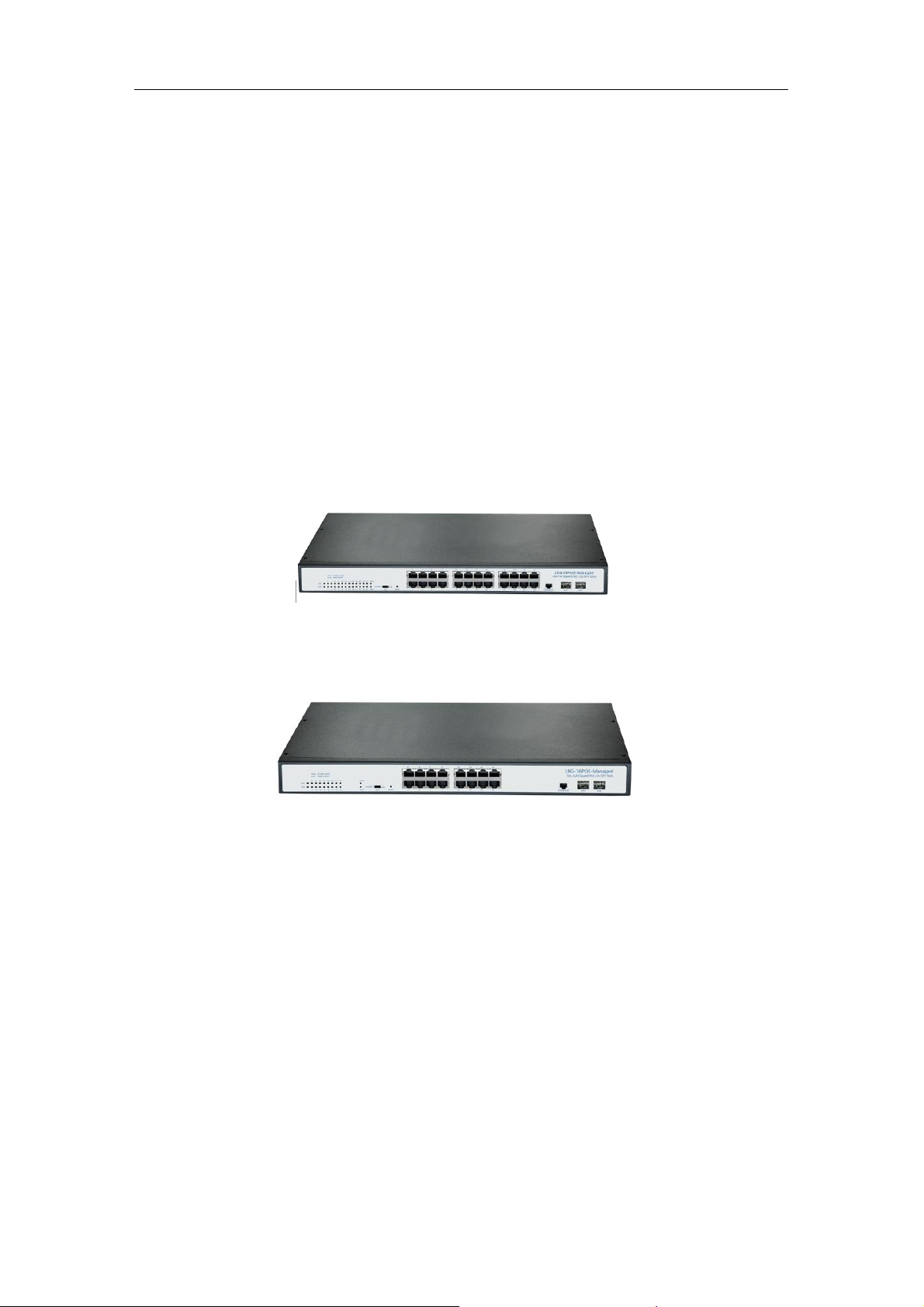
26G-24POE-Manage: 24*10/100/1000M PoE ports,2*1000 Base-X SFP;1*Console port.
18G-16POE-Manage: 16*10/100/1000M PoE ports,2*1000 Base-X SFP;1*Console port.
Switches.
1.2 Front Panel
1. 26G-24POE-Manage
24*10/100/1000M PoE ports,2*1000 Base-X SFP;1*Console port .
Picture 1.2.1 26G-24POE-Manage: Front Panel
2. 18G-16POE-Manage
16*10/100/1000M PoE ports,2*1000 Base-X SFP;1*Console port .
Picture 1.2.1 18G-16POE-Manage Front Panel
LED Indicator Instruction
Please check the LED indicators on the left of front panel.
1. System Indicator
The system indicator is on the upper-left side of front panel, indicator, the indicator is on when
switch works normally.
2. Power Indicator
Below the system indicator is the power indicator, it is on if the switch is powered on.If the
indicator is off, please check the power supply.
3. 10/100Mbps Link/ACT Indicators
Page 5 of 34
Page 6

User’s Guide
Slide the toggle switch to the right “Link/ACT” side,the indicators marked with numbers are
yellow when the 10/100M ports auto-negotiate connected, and the yellow indicators flash
when there are data communications through the ports.
4. 1000Mbps Link/ACT Indicators
Slide the toggle switch to the right “Link/ACT” side,the indicators marked with numbers are
green when the 1000Mbps ports auto-negotiate connected, and the green indicators will
flash when there are data communications through the ports.
5. PoE Indicators
Slide the toggle switch to the right “POE” side, the indicators marked with numbers are yellow
when the PoE function works. And the yellow indicators will flash when the PoE ports failed to
work or the PDs are overloaded, please remove the PD, and reconnect after examination.
1.3 Rear Panel
Picture 1.3.1 Rear Panel
Power Socket: Three-core power socket is adopted,please connect female head of
power cord to the socket, and connect the AC power supply with male head.
Chapter 2 Preparations before Instruction
2.1 Precautions
Please read the following precautions carefully before operation, to avoid damaging the
device or causing body injuries.
1). Please remove the power socket before cleaning the switch. Don’ wipe the switch with wet
cloth or wash the switch with liquid.
2). Don’t stock the device in damp environment or near water, to avoid water or moisture
penetrating into the inner device.
3). Don’t put the device on a unstable box or desk, the device will get damaged from falling.
4). Please keep good ventilation indoor, and make sure the heat dissipation function of switch
works well.
5). The switch only works normally in suitable voltage. Please check the working voltage first.
6). Please don’t open the switch enclosure randomly, especially when the switch is powered
on, there is risk of electric shock.
Page 6 of 34
Page 7
User’s Guide
7). Please wear anti-static wrist strap when change the interface board,to avoid the static
electricity damage the board.
2.2 Check Installation Environment
The switch is for indoor use only, please pay attention to the following problems when install
the switch in a cabinet or put the device directly on the desktop.
1) The air vents of switch must have enough space to dissipate the heat inside enclosure.
2) A good heat dissipation system in the cabinet or on the desktop.
3) The cabinet or desktop strong enough to support the weight of switch and installation
accessories.
4) Safe ground connection for the cabinet or desktop.
2.3 Installation Tools
1) Flathead screw driver
2) Cross screw driver
3) Anti-static wrist strap
Chapter 3 Installation
3.1 Install the Switch
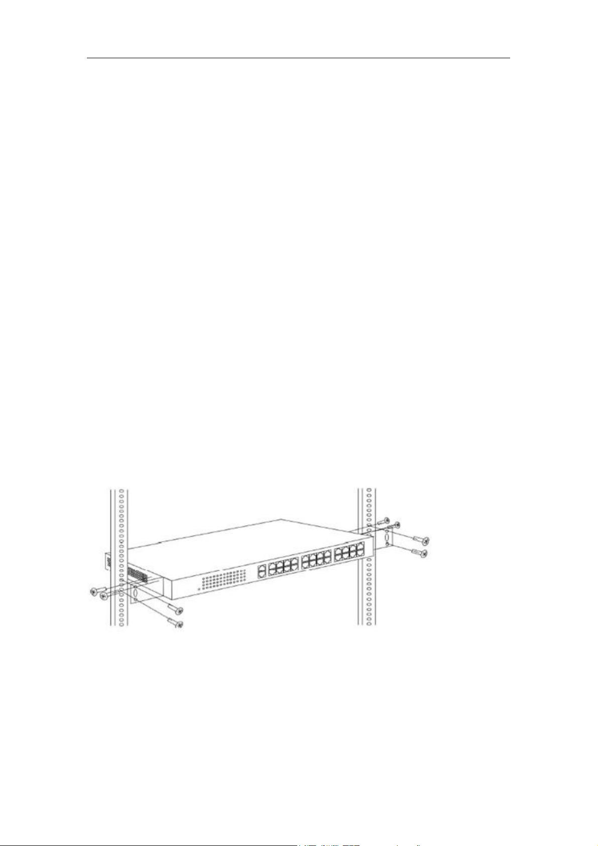
3.1.1 Install the switch on a 19 inch standard cabinet
1) First fix the provided two L-shaped brackets on the two sides of switch.
2) Fix the switch on the rack with screws(screws are not provided).
Picture 3.1.1 Cabinet Installation
3.1.2 Install the switch on the desktop
When there is no 19 inch standard cabinet, the switch is usually put on clean desktop. The
operation is easier, please follow the below instructions:
1) Keep the desktop stable and safely grounded.
2) Set aside 10cm space around switch for heat dissipation.
Page 7 of 34
Page 8

User’s Guide
3) Don’t put any heavy device on the switch.
3.2 Connect the power cord and grounded cord
3.2.1 Select of AC Power Socket
The neutral one-phase 3-wire power socket is advised to adopt, or the multifunctional PC
power socket. The neutral point of power supply must be well grounded, please check the
grounded power supply before operation.
Picture 3.2.1 one-phase 3-wire power socket
3.2.2 Connection of AC power cord
Step one: please connect one end of power cord to the power jack on the switch rear panel,
Connect the other end to the AC power socket.
Step two: check the power indicator(PWR) on the front panel, if the LED is on, connection is
Successful.
3.3 Test after Installation
Make sure the working voltage is the same with the rated voltage of switch.
Check the connection of grounded cord.
Check the connection of configuration cable and power input cord.
If the interface cable is partly deployed outdoor, please check the connection of anti-thunder
AC power strip and interface anti-thunder device.
Page 8 of 34
Page 9

Chapter 4 Technical Specifications
Item
26G-24POE-Manage
18G-16POE-Manage
Fixed Ports
24*10/100/1000 Base-T
16*10/100/1000 Base-T
2*1000 Base-X SFP
PoE standards
IEEE802.3af/at
Max Output Power(single port)
30W
Total Power Consumption
450W
300W
PoE Pin-out
1/2(+),3/6(-);Customized 4/5(+),7/8(-)
Switching Capacity
≥52Gbps
Forwarding Mode
Full wire-speed storage and forwarding
Forwarding Rate
10M:14880pps/port
100M:148809pps/port
1000M:1488095pps/port
Operation Temperature
-20~50°C
Storage Temperature
-40~70°C
Operation Humidity
10%~90%(non-condensing)
Storage Humidity
5%~95%(non-condensing)
Dimensions
280(L)*180(W)*44(H)mm
Input Power Supply
AC:90-264V ~ 50-60Hz
Weight
<10Kg
LED Indicator
Power,Link/Act,PoE Status
Energy Saving
Comply with “EEE” Energy Efficient Ethernet
Item
26G-24POE-Manage
18G-16POE-Manage
Protocol
and Standards
IEEE 802.3, 10 BASE-T Ethernet
IEEE 802.3ad, Static or Dynamic Link Aggregation
IEEE 802.3u,100 BASE-TX
IEEE 802.3ab,1000 BASE-T
IEEE 802.3z,1000 BASE-X
IEEE 802.3x,Full-Duplex Flow Control
IEEE 802.1q,VLAN
IEEE 802.1p,QoS/CoS
IEEE 802.1d, Spanning Tree Protocol
IEEE 802.1w,Rapid Spanning Tree Protocol
IEEE 802.3az,EEE(Energy Efficient Ethernet)
4.1 Hardware Features:
User’s Guide
4.2 Software Features:
Page 9 of 34
Page 10

User’s Guide
IEEE 802.1s,Multiple Spanning Tree Protocol
MAC Address
8K MAC addresses
Support auto-update, two-way learning
VLAN
Supports VLAN based on ports, protocols and ACL
Maximum 4K VLANs
VLANs based on IEEE 802.1q
Spanning Tree
STP Spanning Tree Protocol
RSTP Rapid Spanning Tree Protocol
MSTP Multiple Spanning Tree Protocol
Port Aggregation
8 aggregation groups,each containing up to 8 ports;
Port Mirroring
Many-to-one mirroring(that is, multiple mirroring ports, and
one monitor port)
Loop Protection
Ring protection, real-time detection/quick alarm/accurate
location/intelligent blocking/auto-recovery
Port Isolation
Isolate the communication between ports, only uplink
permitted
Traffic Control
Back-pressure traffic control under Half-Duplex mode
IEEE 802.3x traffic control under Full-Duplex mode
Flow Rate Limitation
Port-based ingress or egress rate limiting
Multicast
IGMPv1/v2/v3 and MLDv1/2 Snooping
Storm Suppression
Supports multiple storm suppression:UC,MC,unknown cast
and broadcast.
Storm suppression based on bandwidth adjustment,storm
filtering and ACL
Supports attack against strategy, against Land attack,Blat
attack,Ping attack and TCL controued Flag attack.
Binding of user port ,IP address and MAC address
Security limitation based on port MAC address quantity
QOS
SP(Strict Priority)
WFQ (Weighted Fair Queuing)
WRR (Weighted Round Robin)
Random Early Detect(RED)
Weighted Random Early Detection(WRED)
Head of Line
802.1p (Port Queuing Priority)
DSCP Priority(Differentiated Service Code Point)
Standard Wiring
Support Auto-MDIX
Negotiation Mode
Auto-negotiation
System Maintenance
Check the connectivity of network cables
Upload/Download configuration files
Upload upgrade patch
View system log
Supports factory reset
Page 10 of 34
Page 11

User’s Guide
Management
Visual web interface management
CLI management
Telnet management
SNMP management
Page 11 of 34
Page 12
User’s Guide
Part Two WEB Configuration Guide
Chapter 1 User Login
Switch adopt Web-based interface management, the default IP is 192.168.255.1. Please
make sure the IP address of PC is in the same network segment with that of switch,or the PC
can’t access to manage the switch. After the setting of IP address, please input
192.168.255.1 in the browser to access the configuration interface of switch.
The Web management interface consists of five parts, which are switch status, basic
configuration, advanced configuration, network security, system maintenance.
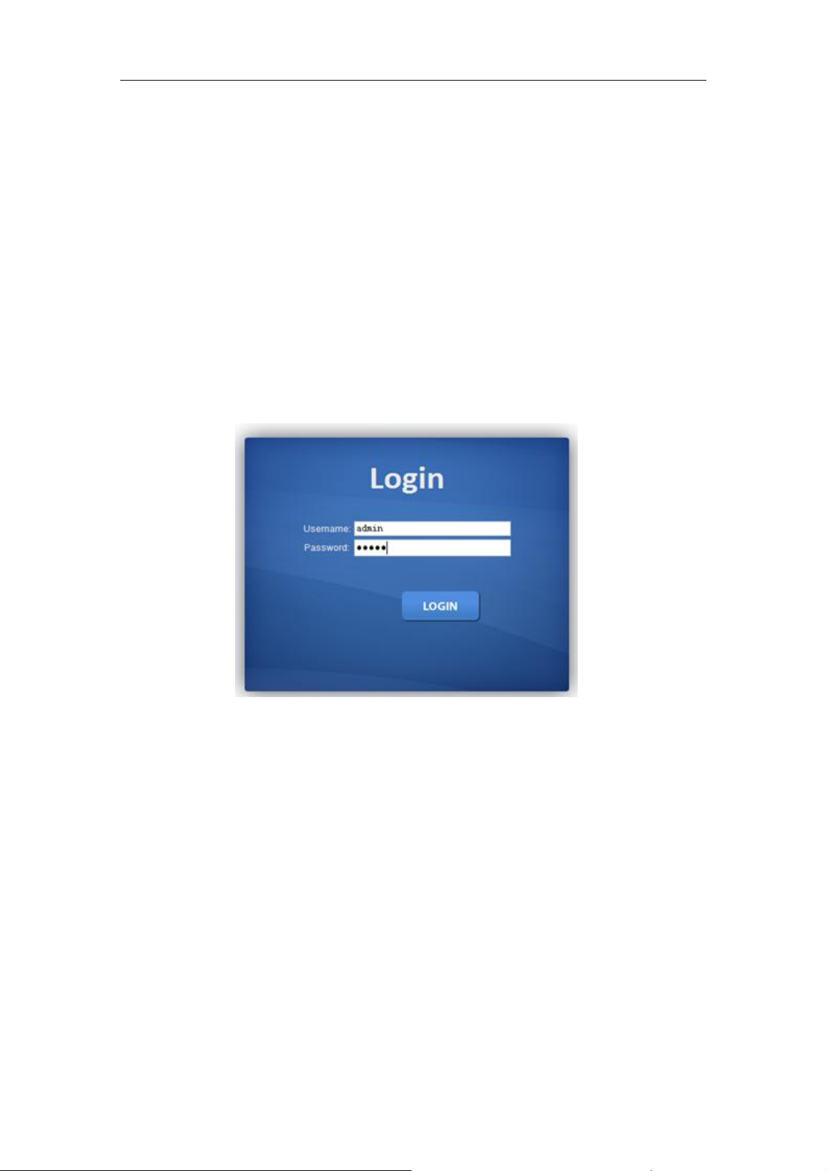
Picture 1.1.1 Login Page
Enter user password in the above login page, the default password is admin. The system only
support single user login, other logins will be refused until the user logs out.
If IP address conflict occurs, it suggests the latest user didn’t log out successfully. Please
reboot the device or try to log in again180s later.
It is advised to reset the IP address and password in first login, and make sure the switch is
not configured in the same network segment with DHCP server or Internet Gateway device.
Page 12 of 34
Page 13

User’s Guide
Chapter 2 Switch Status
2.1 System Information
Picture 2.1.1 System Information
Device status can be checked in the above page, which contains: Device Model
number(equipment type), PCB/HW Version, MAC Address,Serial Number(System Object ID),
Firmware Version, Firmware Updated Date, System Running Time(System Up Time).
2.2 Logging Message
Picture 2.2.1 Logging Message
System log can be checked in above page. Maintenance technicians can check the
history system log.
Page 13 of 34
Page 14
User’s Guide
2.3 Port Counters
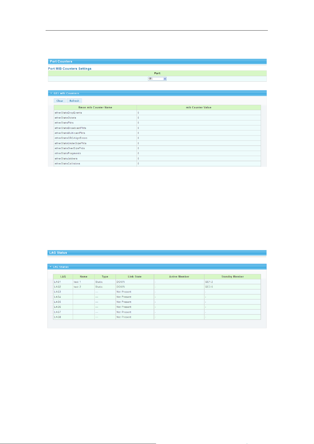
Picture 2.3.1 Port Counters
The above picture shows switch port statistics. Users can check the sent/received
bytes,sent/received packets, wrongly sent/received packets. If there are too many wrong
packets, it suggests the port has very poor working performance, the user need to examine
the connection of network cable or the partner network card.
The current software version doesn’t support real-time statistics refresh, please click
“Refresh” button to get new statistics.
2.4 Link Aggregation
Picture 2.5.1 Link Aggregation
In above Link Aggregation page, user can check the port aggregation information. Like
aggregator group(LAG), link state, aggregator group member state(active/standby).
Page 14 of 34
Page 15

User’s Guide
2.5 LLDP Statistics
Picture 2.6.1 LLDP Statistics
LLDP information can be checked in above page. When enable the LLDP(Link Layer
Discovery Protocol ) function, LLDP information of switch ports can be checked here.
2.6 IGMP Statistics
Picture 2.7.1 IGMP Statistics
When the IGMP snooping function is enabled, IGMP information can be checked in
above page.
Page 15 of 34
Page 16

User’s Guide
2.7 STP Statistics
Picture 2.8.1 STP Statistics
In above STP statistics page, users can check the BPDU packets of every port and every
link aggregation STP.
2.8 MAC Address Table
Picture 2.9.1 MAC Address Table
MAC address table and configuration can be checked in above page, users can add the
showed dynamic MAC addresses to static MAC table.
Page 16 of 34
Page 17

Chapter 3 Basic Configuration
3.1 IP Configuration
User’s Guide
Picture 3.1.1 IP configuration
The above IP address configuration page can be used to configure the IP address of
device management interface “Interface Vlan 1”. The default IP address, subnet mask
and gateway will be showed in the page. When revise the configuration, please press
“save” to confirm new configuration. Press “reset” to back to original configuration.
Above configuration need to be done under default “Static” state,if switch the IP address
mode to DHCP, IP address will be get dynamically. Please record the new IP address for
future login.
Notice: Don’t modify the subnet mask unless exceptional case, login problem will be caused by
improper modification.
3.2 Account Configuration
Picture 3.2.1 Account configuration
Login password can be revised in this page, please remember the new password for
Page 17 of 34
Page 18

User’s Guide
future login.
3.3 Logging Setting
Picture 3.3.1 Logging Setting
System log configuration is checked in above page. Remote log server can be
configured, system log can be saved on the remote server as backup use. Enable or
disable the remote backup function in this page, “server IP address” need to be entered
manually.
3.4 Port Setting
Picture 3.4.1 Port Setting
Port Status: The user can enable or disable a port in this page.Click “Enable” to open the port,
click “Disable” to close the port, the default setting is “Enable”.
Port Mode: 6 modes can be configured:Auto-negotiation,10 Half,10 Full,100 Half, 100 Full
and1000 Full. Default mode is Auto-negotiation, can be changed in pull-down list.
Flow Control: This function is defaulted closed, open it when needed.
Loop Detection:The function is defaulted closed, open it when needed.A port will be blocked
to cut the loop when loop is detected.( Notice: the port link indicator in front panel will be still
on when the port is blocked, for the physic connection is existed; while the link indicator on
Page 18 of 34
Page 19

the top of web management pages will be off.)
Chapter 4 Advanced Configuration
4.1 Port Mirror Configuration
User’s Guide
Picture 4.1.1 Port Mirror Configuration
Users can do Port Mirror Configuration in above page. Port mirroring is used on a network
switch to send a copy of network packets or data traffic from some ports (or an entire VLAN)
to a network monitoring connection on specified switch port. The original port is called Source
Port, and the specified port is Mirroring Port. This is commonly used for network appliances
that require monitoring of network traffic without influencing the normal working of every port,
it’s a convenient online-monitoring function.
All ports have mirroring function, but only one port can be configured as Mirroring Port. In the
same system, there is only one mirroring port, while more than one Source Ports can be
existed. When a port is configured as mirroring port, its corresponding port can’t be
configured as source port.
Page 19 of 34
Page 20

User’s Guide
4.2 Port Aggregation
4.2.1 Static Aggregation
Picture 4.2.1 Static Aggregation
Switches support 8 aggregation groups, each group contains maximum 8 ports. The
members in the same aggregation group should have same configuration for port
forwarding rate mode and VLAN distribution.
If LACP function applied for some ports, then static aggregation can’t be configured.
Notice: Static aggregation can’t be configured when LACP function enabled.
4.2.2 LACP Setting
Picture 4.2.2 LACP Setting
When the LACP protocol is on, the aggregated devices interactively gather information
through LACP. According to the parameters and status of each device, automatically receive
and dispatch Data of matchable link aggregation. When the Aggregation is formed, switches
keep in an aggregation link status, switches automatically adjusts link aggregation or
dissolute when configuration changes.
If the port is configured as static aggregation, the dynamic LACP will be not available.
Notice: Static aggregation LACP function can’t be used together.
Page 20 of 34
Page 21

User’s Guide
4.3 VLAN Management
4.3.1 VLAN Setting
Picture 4.3.1 VLAN Setting
VLAN can be created or deleted in above page. Users can create a new VLAN and give
a name to the VLAN.
4.3.2 VLAN Port Status
Picture 4.3.1 VLAN Port Status
Port features can be configured in above page. Users can create a VLAN and add ports
to the VLAN list with specified mode. VLAN features and port parameters can be
configured.
Ingress Filtering: enable ingress filtering function to abandon or forward unmatched
VLAN packets. This function is default disable, the unmatched packet will be received.
Membership type: tag refers to the port will receive tagged packets(and the VLAN ID in
for tagged packet is not “0”); untag refers to the port receive untagged packets only.
Page 21 of 34
Page 22

User’s Guide
4.4 Voice VLAN
4.4.1 Voice VLAN
Picture 4.4.1 Voice Vlan
Voice VLAN is the VLAN for voice data flow. Create a Voice VLAN and add the ports
connected with voice devices to Voice VLAN, Voice data flow can be centrally
transmitted in Voice VLAN. Users can configure special QoS(Quality of Service) for the
voice data flow, like configure a higher transmitting priority class to ensure a high quality
connection.
4.4.2 Voice VLAN OUI
Picture 4.4.2 Voice Vlan OUI
Voice VLAN signify mode can be configured in this page, like Siemens AG phones、Cisco
phones、H3C phones……
Page 22 of 34
Page 23

User’s Guide
4.5 Multicast Configuration
Picture 4.5.1 Multicast Configuration
MLD Snooping is short for Multicast Listener Discovery Snooping, which is IPv6
multicast control mechanism for Layer 2 devices. The function is used to manage and
control IPv6 multicast.
Multicast snooping configuration can be made in above page, enable or disable multicast
snooping and define multicast snooping address range.
4.6 IGMP Snooping Configuration
Picture 4.6.1 IGMP Snooping
IGMP snooping configuration can be made in above page, enable or disable IGMP
snooping and define IGMP snooping address range.
4.7 Jumbo Frame Configuration
Page 23 of 34
Page 24

User’s Guide
Picture 4.7.1 Jumbo Frame Configuration
Generally, the max frame size for packet is 1518 Bytes, when packet is larger than this
size, it will be processed in batch, 1518 Bytes as a unit. And users can also set a Jumbo
Frame limitation in this page(from 1522 to 9216 Bytes), enable Jumbo Frames
transmitted smoothly, reduce the load.
4.8 Static MAC Address Table
Picture 4.8.1 Static ARP Table
Static MAC address configuration can be manually made in this page. MAC items can be
added according “port”,”VLAN ID”,”MAC address” and “IP address”.
4.9 Dynamic MAC Address Configuration
Picture 4.9.1 Dynamic MAC Address Configuration
In above dynamic address setting page, users can check the aging time of MAC
address.
Page 24 of 34
Page 25

User’s Guide
4.10 LLDP Configuration
Picture 4.10.1 LLDP Configuration
Switches support LLDP(Link Layer Discovery Protocol), which can define switch
capacity, management address, device tags and port tags as
different(TLV(type/length/value) and save them in LLDPDU (Link Layer Discovery
Protocol Data Unit). These information will be released to the direct-connected neighbor
device, neighbor devices will save these information based on MIB(Management
Information Base) . These information will be used for network management system
examination or judge link communication condition.
LLDP information can be configured in above page, including transmission interval,hold
time Multiplier,retransmission delay and transmission delay.
Enable LLDP or Disable LLDP can be configured. Users can also configure the
information transmitted to neighbor devices, like port description, system name, system
description, system property and management address.
4.11 SNMP Configuration
4.11.1 SNMP system configuration
Picture 4.11.1 SNMP System Configuration
SNMP(Simple Network Management Protocol) is Internet-standard protocol for
managing devices on IP networks.It consists of a set of standards for network
Page 25 of 34
Page 26

User’s Guide
management, including anapplication layer protocol, a database schema, and a set of
data objects. SNMP is used mostly in network management systems to monitor
network-attached devices for conditions that warrant administrative attention.
4.11.2 SNMP Community configuration
Picture 4.11.2 SNMP Community Configuration
Configure SNMP common identifiers, switches with same community identifier can make
unified management.
4.11.3 Trap Configuration
Picture 4.12 Trap Configuration
SNMP trap is a message used in SNMP protocol, the device can send a trap message to
SNMP manager when they experience a problem, rather than waiting for the polling of
SNMP manager.
4.12 PoE Management
Trap Configuration
From above interface 4.9.1,you can find “Enable/disable”to enable or disable PoE supply
power to powered device.
From the Priority,you can find Low,Middle and High to ensure power output of the port
with the highest priority. You can check current currency from column“(mA)”,Voltage from
column“(V)”
Page 26 of 34
Page 27

User’s Guide
and power from column“(W)” and PoE output grade from column “(Class)”
The default setting is “0”for 0-13W PD, ”1” for less than 4W PD, “2” for 4-7W PD.
“3”for 7-13W PD,”4” for IEEE802.3at PD, “5,6” kept as potential grade.
You can find PoE supply power normally or not from “Status” column or LED indicators
status from Front panel of the Switch.
Chapter 5 Network Security
5.1 Port Limit Configuration
Picture 5.1.1 Ingress Bandwidth Control
Picture 5.1.2 egress Bandwidth Control
Page 27 of 34
Page 28

User’s Guide
Picture 5.1.3 Egress Queue Bandwidth
Switch Bandwidth can be configured in above pages. Configurations include
ingress/egress flow control, flow control priority class.
5.2 Storm Control
Picture 5.2.1 Storm control
Picture 5.2.2 Storm control Port Configuration
After enable the global situation storm control, please continue with function
Page 28 of 34
Page 29

User’s Guide
configuration. The switch supports multiple storm control modes, like broadcast storm
control, unknown multicast storm control and unknown unitcast storm control.
5.3 Port Isolation
Picture 5.3.1 Port Isolation Configuration
In above port isolation page, isolated ports can be configured. Applying port isolation
function to ensure port security.
5.4 DoS configuration
Picture 5.4.1 Global Dos Configuration
Page 29 of 34
Page 30

User’s Guide
Picture 5.4.2 Dos Port Configuration
Dos is short for Denial of Service, what causes DoS problem is DoS attacks, which will
block the normal network service. The most common DoS attacks are computer network
bandwidth attack and connectivity attack. Please configure DoS information in above
pages.
5.5 STP Configuration
Picture 5.5.1 STP Global configuration
Page 30 of 34
Page 31

Picture 5.5.2 STP Port configuration
User’s Guide
Picture 5.5.3 STP Bridge Configuration
STP configurations can be made in above pages. Users can choose from STP and
RSTP modes according to different network requirements.
Chapter 6 System Maintenance
6.1 Reboot Switch
Picture 6.1.1 Reboot Switch
Above page is used to reboot switch. When manage the switch, some configurations need to
reboot the switch to take effect.
Page 31 of 34
Page 32

User’s Guide
6.2 Factory Reset
Picture 6.2.1 Factory Reset
The switch support factory reset, press “restore” button to back factory default settings,
including all configurations, IP address and management password.
6.3 Firmware Upgrading
Picture 6.3.1 Firmware Upgrading
Current system software version can be checked in this page, and new software upgrade
can be made.
6.4 Ping Test
Picture 6.4.1 Ping Test Configuration
Ping test is to check if a specified Client can be reached, the function is the same with ping
command under windows command lines. The IP addresses of switch and PC must be in
same network segment.
Page 32 of 34
Page 33

User’s Guide
6.5 IPv6 Ping Test
Picture 6.5.1 IPv6 Ping Test Configuration
Ping test is to check if a specified Client can be reached, the function is the same with ping
command under windows command lines. The IP addresses of switch and PC must be in
same network segment.
6.6 Network Cable Test
Picture 6.6.1 Network Cable Test
Users can test the twisted pair cable working status. Please select test ports then press
“cooper test” to check the working status.
Page 33 of 34
Page 34

Appendix Trouble shooting
Problems
Reasons
Solutions
All LEDs are off when
power on the switch
Power cord connection error or
power supply failure
Check power cord connection and the
power socket.
The LINK LED is unlit.
1.Network cable is damaged or
the connection is not firm.
2.Wrong network cable type or
the cable is longer than 100m.
Change the network cable.
Slower data transmitting
and packets loss.
The communication pattern of
switch and PDs are not matched.
Changed to matched pattern or configure
to auto-negotiation pattern.
The network cable
works in one
port ,doesn’t work in
another new port.
There is no data transmitting from
PD and the switch can’t learn a
new address to do
communication.
Waiting for 120s, the swith will get
auto-updated address or transmitting
data from the PD, the switch will get
address then.
All the “ACT” LEDs flash
and the network rate
slow down
Caused by broadcast storm.
1. Check if there is a loop problem,
reasonably configure the network.
2. Check if there are large numbers of
broadcast packets from specific sites.
Stop to work after
working for a while.
1. Abnormal power supply.
2. Overheating.
1. Check power connection and the
working voltage;
2. Check the working
environment,including air hole and
switch fan.
“PoE” LED indicators
flash
1. PoE port doesn’t work
2. PD is overloaded
3. The network cable is damaged.
Check the network cable, port
connection or reduce the load of PDs.
User’s Guide
Page 34 of 34
 Loading...