


NVR-708NS

Network Video Recorder User’s Manual
V 2.1.1

i
Table of Contents
1 Features and Specifications ...............................................................................................................1
1.1 Overview........................................................................................................................................1
1.2 Features.........................................................................................................................................1
1.3 Specifications................................................................................................................................2
1.3.1 NVR7XXNS Series................................................................................................................2
1.3.2 NVR6XXV Series...................................................................................................................3
1.3.3 NVR7XXN Series ..................................................................................................................5
2 Front Panel and Rear Panel ...............................................................................................................7
2.1 Front Panel....................................................................................................................................7
2.1.1 NVR7XXNS Series................................................................................................................7
2.1.2 NVR6XXV Series...................................................................................................................8
2.1.3 NVR7XXN Series ................................................................................................................10
2.2 Rear Panel ..................................................................................................................................12
2.2.1 NVR7XXNS Series..............................................................................................................12
2.2.2 NVR6XXV Series.................................................................................................................14
2.2.3 NVR7XXN Series ................................................................................................................15
2.3 Alarm Connection.......................................................................................................................17
2.4 Bidirectional talk .........................................................................................................................17
2.4.1 Device-end to PC-end ........................................................................................................17
2.4.2 PC-end to the device-end ..................................................................................................18
2.5 Mouse Operation........................................................................................................................18
3 HDD Installation..................................................................................................................................20
3.1 NVR7XXNS Series.....................................................................................................................20
3.2 NVR6XXV Series .......................................................................................................................21
3.3 NVR7XXN Series .......................................................................................................................21
4 Network Connection ..........................................................................................................................23
5
System Performance .........................................................................................................................24

ii
6 GUI Operation.....................................................................................................................................25
6.1 Login.............................................................................................................................................25
6.2 Right Click Menu ........................................................................................................................27
6.3 Main Menu...................................................................................................................................27
6.4 Search & Playback.....................................................................................................................28
6.5 Information ..................................................................................................................................31
6.5.1 HDD Information..................................................................................................................32
6.5.2 BPS........................................................................................................................................33
6.5.3 Log.........................................................................................................................................33
6.5.4 Version ..................................................................................................................................34
6.5.5 Online Users.........................................................................................................................35
6.5.6 Remote Device Information ...............................................................................................35
6.6 Setting..........................................................................................................................................36
6.6.1 General .................................................................................................................................37
6.6.2 Encode ..................................................................................................................................38
6.6.3 Schedule...............................................................................................................................40
6.6.3.1 Quick Setup.................................................................................................................41
6.6.4 RS232 ...................................................................................................................................42
6.6.5 Network.................................................................................................................................43
6.6.5.1 Network Seting ...........................................................................................................44
6.6.5.2 IP Filter.........................................................................................................................44
6.6.5.3 NTP Setup...................................................................................................................45
6.6.5.4 Multiple Cast Setup....................................................................................................46
6.6.5.5 PPPoE..........................................................................................................................47
6.6.5.6 DDNS Setup................................................................................................................47
6.6.5.7 UPNP ...........................................................................................................................49
6.6.5.8 WIFI Setting.................................................................................................................50
6.6.5.9 Email ............................................................................................................................52
6.6.5.10 FTP...............................................................................................................................53
6.6.5.11 Alarm center................................................................................................................55
6.6.5.12 SNMP...........................................................................................................................55
6.6.5.13 Auto register................................................................................................................56
6.6.6 Alarm .....................................................................................................................................57
6.6.7 Detect ....................................................................................................................................60
6.6.8 PTZ ........................................................................................................................................ 64
6.6.9 Display ..................................................................................................................................65
6.6.10 Default...................................................................................................................................67
6.6.11 Remote Device ....................................................................................................................67
6.6.11.1 UPNP ...........................................................................................................................67

iii
6.6.11.2 Built-in Switch Setup ..................................................................................................68
6.6.11.3 Remote Device ...........................................................................................................68
6.6.11.4 Short-cut Menu.............................................................................................................70
6.7 Advanced.....................................................................................................................................71
6.7.1 HDD Management...............................................................................................................71
6.7.2 Abnormity..............................................................................................................................75
6.7.3 Alarm Output ........................................................................................................................75
6.7.4 Manual Record.....................................................................................................................76
6.7.4.1 Manual record menu..................................................................................................76
6.7.4.2 Basic operation................................................................................................................76
6.7.4.3 Enable/disable record ................................................................................................76
6.7.4.4 Enable all channel recording ....................................................................................77
6.7.4.5 Stop all channel recording.........................................................................................77
6.7.5 Account .................................................................................................................................78
6.7.5.1 Modify Password ........................................................................................................79
6.7.5.2 Add/Modify Group ......................................................................................................79
6.7.5.3 Add/Modify User .........................................................................................................80
6.7.6 Auto Maintenance ...............................................................................................................80
6.7.7 Config Backup......................................................................................................................81
6.8 Shutdown.....................................................................................................................................81
7 Quick Configuration Tool...................................................................................................................83
7.1 Overview......................................................................................................................................83
7.2 Operation.....................................................................................................................................83
8 Web Operation....................................................................................................................................86
8.1 General Introduction
..................................................................................................................86
8.1.1 Preparation ...........................................................................................................................86
8.1.2 Log in.....................................................................................................................................86
8.2 LAN Mode....................................................................................................................................88
8.2.1 Monitor Channel Menu Tree ..............................................................................................88
8.2.2 System Menu .......................................................................................................................91
8.2.3 Monitor Window Switch ......................................................................................................91
8.2.4 PTZ Control ..........................................................................................................................91
8.2.5 Color and More Setup.........................................................................................................93
8.3 WAN Login .................................................................................................................................. 94
8.4 Configuration...............................................................................................................................96
8.4.1 System Information .............................................................................................................96

iv
8.4.1.1 Version Information....................................................................................................96
8.4.1.2 HDD information .........................................................................................................97
8.4.1.3 Log................................................................................................................................97
8.4.2 System Configuration .........................................................................................................98
8.4.2.1 General Setup.............................................................................................................98
8.4.2.2 Encode.......................................................................................................................100
8.4.2.3 Schedule....................................................................................................................101
8.4.2.4 RS232 ........................................................................................................................103
8.4.2.5 Network......................................................................................................................104
8.4.2.6 Alarm ..........................................................................................................................112
8.4.2.1 Detect.........................................................................................................................114
8.4.2.2 PTZ.............................................................................................................................116
8.4.2.3 Default & Backup......................................................................................................117
8.4.3 Advanced............................................................................................................................118
8.4.3.1 HDD Management ...................................................................................................118
8.4.3.2 Abnormity...................................................................................................................119
8.4.3.3 Alarm I/O....................................................................................................................120
8.4.3.4 Record........................................................................................................................121
8.4.3.5 Account ......................................................................................................................121
8.4.3.6 Snapshot....................................................................................................................123
8.4.3.7 Auto Maintenance ....................................................................................................123
8.4.3.8 Remote device..........................................................................................................124
8.4.3.9 Preview Control.............................................................................................................125
8.4.4 Additional Function............................................................................................................126
8.4.4.1 Auto register
..............................................................................................................126
8.4.4.2 Mobile Config ............................................................................................................126
8.4.4.3 WIFI Config ...............................................................................................................127
8.5 Search........................................................................................................................................128
8.6 Alarm..........................................................................................................................................131
8.7 About..........................................................................................................................................133
8.8 Log out .......................................................................................................................................133
9 FAQ ....................................................................................................................................................134
10 Appendix A HDD Capacity Calculation.....................................................................................139
11 Appendix B Compatible SATA HDD..........................................................................................140
12 Appendix C Compatible USB List..............................................................................................142
13 Appendix D Compatible Displayer List......................................................................................144

v
14 Appendix E No-IP DDNS ............................................................................................................145
Appendix H Toxic or Hazardous Materials or Elements.....................................................................152

vi
Welcome
Thank you for purchasing our network video recorder!
This user’s manual is designed to be a reference tool for your system.
Please open the accessory bag to check the items one by one in accordance with the list below.
Contact your local retailer ASAP if something is missing or damaged in the bag.

vii
Important Safeguards and Warnings
1.Electrical safety
All installation and operation here should conform to your local electrical safety codes.
We assume no liability or responsibility for all the fires or electrical shock caused by improper
handling or installation.
2.Transportation security
Heavy stress, violent vibration or water splash are not allowed during transportation, storage and
installation.
3.Installation
Keep upwards. Handle with care.
Do not apply power to the NVR before completing installation.
Do not place objects on the NVR
4.Qualified engineers needed
All the examination and repair work should be done by the qualified service engineers.
We are not liable for any problems caused by unauthorized modifications or attempted repair.
5.Environment
The NVR should be installed in a cool, dry place away from direct sunlight, inflammable, explosive
substances and etc.
This series product shall be transported, storage and used in the environment ranging from 0℃ to
50 ℃
6. Accessories
Be sure to use all the accessories recommended by manufacturer.
Before installation, please open the package and check all the components are included.
Contact your local retailer ASAP if something is broken in your package.
7. Lithium battery
Improper battery use may result in fire, explosion, or personal injury!
When replace the battery, please make sure you are using the same model!
Before your operation please read the following instructions carefully.
z Installation environment
Keep away from extreme hot places and sources;
Avoid direct sunlight;
Keep away from extreme humid places;
Avoid violent vibration;
Do not put other devices on the top of the NVR;
Be installed in well ventilated place; do not block the vent.

viii
z Accessories
Check the accessories after opening the box:
z Please refer to the packing list in the box *

1
1 Features and Specifications
1.1 Overview
This series NVR is a high performance network video recorder. This series product support local
preview, multiple-window display, recorded file local storage, remote control and mouse shortcut
menu operation, and remote management and control function. All these functions support this
series product to be used in various situations.
This series product supports centre storage, front-end storage and client-end storage. The
monitor zone in the front-end can be set in anywhere. Working with other front-end devices such
as IPC, NVS, this series product can establish a strong surveillance network via the CMS. In the
network system, there is only one network cable from the monitor centre to the monitor zone in
the whole network. There is no audio/video cable from the monitor centre to the monitor zone. The
whole project is featuring of simple connection, low-cost, low maintenance work.
This series NVR can be widely used in many areas such as public security, water conservancy,
transportation and education.
1.2 Features
User
Management
• ·Each group has different management powers that can be edited freely.
Every user belongs to an exclusive group.
Storage
• Via corresponding setup (such as alarm setup and schedule setup), you
can backup related audio/video data in the network video recorder.
• Support Web record and record local video and storage the file in the
client end.
Alarm
• Respond to external alarm simultaneously (within 200MS), based on
user’s pre-defined relay setup, system can process the alarm input
correctly and prompt user by screen and voice (support pre-recorded
audio).
• Support central alarm server setup, so that alarm information can
remotely notify user automatically. Alarm input can be derived from
various connected peripheral devices.
• Alert you via EMAIL.
Network
Monitor
• Through network, sending audio/video data compressed by IPC or NVS
to client-ends, then the data will be decompressed and display. If
bandwidth is big enough, latency is less than 500ms
• Support max 10 connections
• Transmit audio/video data by HTTP, TCP, UDP, MULTICAST,
RTP/RTCP and etc.
• Transmit some alarm data or alarm info by SMTP.
• Support WEB access in WAN.
Window Split
• Adopt the video compression and digital process to show several
windows in one monitor. Support 1/4/9/16-window display.

2
Record
• Support schedule record function. Save the recorded files in the HDD,
client-end PC, or network storage server. You can search or playback
the saved files at the local-end or via the Web.
Backup
• Support network backup, USB record backup function, the recorded files
can be saved in network storage server, peripheral USB device,
burner and etc.
Network
Management
• Supervise NVR configuration and control power via Ethernet.
• Support management via WEB.
Peripheral
Equipment
Management
• Support peripheral equipment management such as protocol setup and
port connection.
• Support transparent data transmission through RS232/RS485.
Auxiliary
• Support switch between NTSC and PAL.
• Support real-time system resources information and running statistics
display.
• Support log file.
• Local GUI output. Shortcut menu operation via mouse.
• IR control function. Shortcut menu operation via remote control.
• Support IPC or NVS remote video preview and control.
1.3 Specifications
1.3.1 NVR7XXNS Series
Specifications Parameter
NVR7XXNS Series
System
Resources
Max support 16-ch standard definition with the transmission rate of 2mbps for each
channel;
8-channel 720P, with the transmission rate of 4mbps for each channel;
4-channel 1080P, with the transmission rate of 8mbps for each channel;
Support 20 online users at the same time,
The image delay time of each channel is under 500ms.
Operation
System
Embedded Linux real-time operation system
Operation
Interface
WEB/Local GUI
Video
Compression
H.264/MPEG4
Encode
Capacity
For H.264, it max supports 16*D1, 8*720,4*1080P.
Audio
Compression
G.711a
Video Output
1-channel VGA analog video output.
Video Input
4/8/16-ch network compression video input
HDMI
1-ch HDMI output.
Audio Input
1-ch bidirectional audio input
Audio Output
1-ch bidirectional talk output.

3
Window Split
4/8/9/16-window
Multiple-chann
el Playback
Max 16-channel playback.
Alarm Input
4/8/16-ch series product support 4/8/16-ch alarm input respectively.
3-ch alarm output
Alarm Output
Relay output. Relay (DC 30V 1A,AC 125V 0.5A(Activation output))
Including one controllable DC +12V output.
Storage
2 built-in SATA ports.
RS232 Port
One RS232 port to debug transparent COM data.
RS485 port
One RS485 port to control PTZ. Support various protocols.
USB Port
2 peripheral USB ports.
Network
Connection
One RJ45 10/100M/1000M self-adaptive Ethernet port.
Power Port
Two power ports, power adapter. Input DC 12V or DC 48V.
Power Button
One power button in the rear panel.
Power Button
One power button in the front panel.
IR Remote
Control
Receiver
N/A
Clock
Built-in clock.
Indication Light
z 16 record status indication lights
z One power status indication light.
z One alarm status indication light.
z One network status indication light.
z One HDD status indication light.
Power
Consumption
<12W(Exclude HDD)
Working
Temperature
0℃~+50℃
Working
Humidity
10℅-90℅
Air pressure
86kpa-106kpa
Dimension
440mm*300mm*42.6mm
Weight
1.5~2.5 KG(Exclude HDD)
Installation
Desk installation/Rack installation
1.3.2 NVR6XXV Series
Parameter Specifications

4
NVR6XXV Series
System
Resources
Max support 16-ch standard definition with the transmission rate of 2mbps for each
channel;
8-channel 720P, with the transmission rate of 4mbps for each channel;
4-channel 1080P, with the transmission rate of 8mbps for each channel;
Support 20 online users at the same time,
The image delay time of each channel is under 500ms.
Operation
System
Embedded Linux real-time operation system
Operation
Interface
WEB/Local GUI
Video
Compression
H.264/MPEG4
Encode
Capacity
For H.264, it max supports 16*D1, 8*720,4*1080P.
Audio
Compression
G.711a
Video Output
1-channel VGA analog video output.
Video Input
4/8/16-ch network compression video input
HDMI
1-ch HDMI output.
Audio Input
1-ch bidirectional audio input
Audio Output
1-channel bidirectional talk output.
Window Split
4/8/9/16-window
Multiple-chann
el Playback
Max 16-channel playback.
Alarm Input
4/8/16-ch series product support 4/8/16-ch alarm input respectively.
3-ch alarm output
Alarm Output
Relay output. Relay (DC 30V 1A,AC 125V 0.5A(Activation output))
Including one controllable DC +12V output.
2 built-in SATA ports
Storage
1 peripheral eSATA port
RS485 port
One RS485 port to control PTZ. Support various protocols.
USB Port
3 peripheral USB ports.
Network
Connection
One RJ45 10/100M/1000M self-adaptive Ethernet port.
Power Port
Two power ports, power adapter. Input DC 12V or DC 48V.

5
Power Button
One power button in the rear panel.
Power Button
One power button in the front panel.
IR Remote
Control
Receiver
N/A
Clock
Built-in clock.
Power
Consumption
<12W(Exclude HDD)
Working
Temperature
0℃~+50℃
Working
Humidity
10℅-90℅
Air pressure
86kpa-106kpa
Dimension
440mm*300mm*42.6mm
Weight
1.5~2.5 KG(Exclude HDD)
Installation
Desk installation
1.3.3 NVR7XXN Series
Specifications Parameter
NVR7XXN Series
System
Resources
Max support 16-ch standard definition with the transmission rate of 2mbps for each
channel;
8-channel 720P, with the transmission rate of 4mbps for each channel;
4-channel 1080P, with the transmission rate of 8mbps for each channel;
Support 20 online users at the same time,
The image delay time of each channel is under 500ms.
Operation
System
Embedded Linux real-time operation system
Operation
Interface
WEB/Local GUI
Video
Compression
H.264/MPEG4
Encode
Capacity
For H.264, it max supports 16*D1, 8*720, 4*1080P.
Audio
Compression
G.711a
Video Output
1-channel VGA analog video output.
Video Input
4/8/16-ch network compression digital video input
HDMI
1-ch HDMI output.
Audio Input
1-ch bidirectional audio input
Audio Output
1-channel bidirectional talk output.

6
Window Split
4/8/9/16-window
Multiple-chann
el Playback
Max 16-channel playback.
Alarm Input
4/8/16-ch series product support 4/8/16-ch alarm input respectively.
6-ch alarm output
Alarm Output
Relay output. Relay (DC 30V 1A,AC 125V 0.5A(Activation output))
Including one controllable DC +12V output.
8 built-in SATA ports
Storage
1 peripheral eSATA port
RS232 Port
One RS232 port to debug transparent COM data.
RS485 port
One RS485 port to control PTZ. Support various protocols.
USB Port
4 peripheral USB ports.
Network
Connection
One RJ45 10/100M/1000M self-adaptive Ethernet port.
Power Port
One power port. AC100~240V 50+2% Hz
Power Button
One power button in the rear panel.
Power Button
One power button in the front panel.
IR Remote
Control
Receiver
One IR remote control receiver in the front panel.
Clock
Built-in clock.
Indication Light
z 16 record status indication lights
z One system running status indication light.
z One remote control indication light.
Power
Consumption
<40W(Exclude HDD)
Working
Temperature
0℃~+50℃
Working
Humidity
10℅-90℅
Air pressure
86kpa-106kpa
Dimension
440mm*460mm*89mm
Weight
5.5~6.5KG(Exclude HDD)
Installation
Desk installation/Rack installation

7
2 Front Panel and Rear Panel
2.1 Front Panel
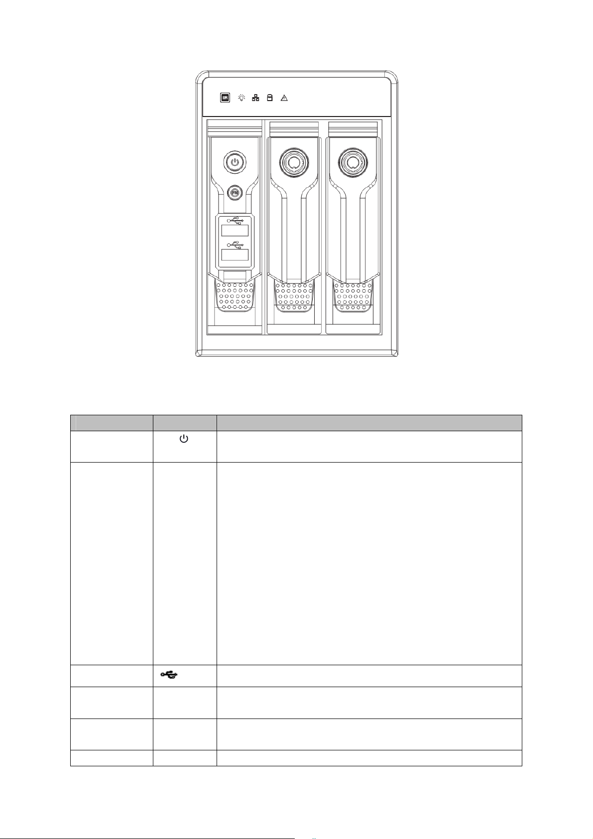
2.1.1 NVR7XXNS Series
The front panel is shown as in Figure 2-1.
Figure 2-1
Please refer to the following sheet for front panel button information.
Name Icon Function
Power button
Power button, press this button for three seconds to boot up
or shut down DVR.
Shift Shift
In textbox, click this button to switch between numeral,
English(Small/Capitalized),donation and etc.
Activate current control, modify setup, and then move up and
down.
Increase/decrease numeral.
Assistant function such as PTZ menu.
Up/1
Down/4
S、T
In text mode, input number 1/4 (English character G/H/I)
Shift current activated control,
Left/2
Right/3
W X
When playback, click these buttons to control playback bar.
In text mode, input number 2(English character A/B/C)
/3(English character D/E/F)
Go to previous menu, or cancel current operation.
ESC ESC
When playback, click it to restore real-time monitor mode.
Confirm current operation
Go to default button
Enter ENTER
Go to menu
Record REC
Manually stop/start recording, working with direction keys
or numeral keys to select the recording channel.
Slow play/8
Multiple slow play speeds or normal playback.
In text mode, input number 8 (English character T/U/V).
Assistant Fn
One-window monitor mode, click this button to display

8
Backspace function: in numeral control or text control, press
it for 1.5seconds to delete the previous character before the
In motion detection setup, working with Fn and direction keys
to realize setup.
In text mode, click it to switch between numeral, English
character(small/capitalized) and etc.
Realize other special functions.
Fast play/7
Various fast speeds and normal playback.
In text mode, input number 7 (English character P/Q/R/S).
Play
previous/0
_
In playback mode, playback the previous video
In text mode, input number 0.
Reverse/Pau
se/6
W
In normal playback or pause mode, click this button to
reverse
playback
In reverse playback, click this button to pause playback.
Play Next/9
f
In playback mode, playback the next video
In menu setup, go to down ward of the dropdown list.
In text mode, input number 9 (English character W/X/Y/Z)
Play/Pause /5
f
In normal playback click this button to pause playback
In pause mode, click this button to resume playback.
In text mode, input number 5(English character J/K/L).
USB port
To connect USB storage device, USB mouse.
Network
abnormal
indication
Net
Network error occurs or there is no network connection, the
light becomes red to alert you.
HDD
abnormal
indication
HDD
HDD error occurs or HDD capacity is below specified
threshold value, the light becomes red to alert you.
Record light 1-16
System is recording or not. It becomes on when system is
IR Receiver IR
It is to receive the signal from the remote control.
Alarm
indication
light
Alarm
Here you can view there is external alarm input or not. The
light becomes on when there is an external alarm. The light
become off when the external alarm stops.
2.1.2 NVR6XXV Series
The front panel is shown as below. See Figure 2-2.
9
Figure 2-2
Please refer to the following sheet for front panel button information.
Name Icon Function
Power button Power button, press this button for three seconds to boot up or
shut down NVR.
Assistant Fn
z One-window monitor mode, click this button to display
assistant function: PTZ control and image color.
z Backspace function: in numeral control or text control,
press it for 1.5 seconds to delete the previous character
before the cursor.
z In motion detection setup, working with Fn and direction
keys to realize setup.
z In text mode, click it to switch between numeral, English
character (small/capitalized) and etc.
z In HDD management interface, you can click it to switch
HDD record information and other information (Menu
prompt)
z Realize other special functions.
USB port
To connect USB storage device, USB mouse, burner and etc.
Power
indication light
Power
Power indication light.
HDD abnormal
indication light
HDD
HDD error occurs or HDD capacity is below specified threshold
value, the light becomes red to alert you.
Network
Net
Network error occurs or there is no network connection, the light

10
abnormal
indication light
becomes red to alert you.
IR Receiver
IR
It is to receive the signal from the remote control.
2.1.3 NVR7XXN Series
The front panel is shown as in Figure 2-3.
Figure 2-3
Please refer to the following sheet for front panel button information.
Name Icon Function
Power button
Power button, press this button for three seconds to boot up
or shut down DVR.
0
In text mode, input number 0.
It is the space button.
1,. In text mode, input number 1 and denotation.
2ABC
In text mode, input number 2(English character A/B/C)
3DEF
In text mode, input number 3(English character D/E/F)
4GHI In text mode, input number 4 (English character G/H/I)
5JKL In text mode, input number 5(English character J/K/L).
6MNO
In text mode, input number 6 (English character M/N/O)
7PQRS In text mode, input number 7 (English character P/Q/R/S).
8TUV In text mode, input number 8 (English character T/U/V).
9WXYZ
In text mode, input number 9 (English character W/X/Y/Z)
Number and
Character
-/--
If you want to input a number more than 10, please click this
button and then input.
Shift
In textbox, click this button to switch between numeral,
English(Small/Capitalized),donation and etc.
Activate current control, modify setup, and then move up and
down.
Increase/decrease numeral.
Up
Down
S、T
Assistant function such as PTZ menu.

11
Shift current activated control,
Left
Right
W X
When playback, click these buttons to control playback bar.
Go to previous menu, or cancel current operation.
ESC ESC
When playback, click it to restore real-time monitor mode.
Confirm current operation
Go to default button
Enter ENTER
Go to menu
Record REC
Manually stop/start recording, working with direction keys
or numeral keys to select the recording channel.
Window switch
Mult
Click it to switch one-window/multi
p
le-window.
Slow play/8
Multiple slow play speeds or normal playback.
One-window monitor mode, click this button to display
assistant function: PTZ control and image color.
Backspace function: in numeral control or text control, press
it for 1.5seconds to delete the previous character before the
In motion detection setup, working with Fn and direction keys
to realize setup.
In text mode, click it to switch between numeral, English
character(small/capitalized) and etc.
Assistant Fn
Realize other special functions.
Fast play
Various fast speeds and normal playback.
Play previous
_
In playback mode, playback the previous video
Reverse/Pau
se
W
In normal playback or pause mode, click this button to
reverse
playback
In reverse playback, click this button to pause playback.
Play Next
f
In playback mode, playback the next video
In menu setup, go to down ward of the dropdown list.
Play/Pause
f
In normal playback click this button to pause playback
In pause mode, click this button to resume playback.
USB port
To connect USB storage device, USB mouse.

12
Status
indication
li
g
ht
Status
If there is Fn indication light, current status indication light is
null.
HDD
abnormal
HDD
HDD error occurs or HDD capacity is below specified
threshold value, the light becomes red to alert you.
Remote
control
indication
light
ACT Remote control indication light
Power
indication
light
Power Power indication light
Record light 1-16
System is recording or not. It becomes on when system is
recording.
For this series product, the last 12 lights are null since there
is only four channels.
IR Receiver IR
It is to receive the signal from the remote control.
Shuttle(outer
ring)
In real-time monitor mode it works as left/right direction key.
Playback mode, counter clockwise to forward and clock wise
to backward.
Jog(inner
dial)
Up/down direction key.
Playback mode, turn the inner dial to realized frame by frame
playback. (Only applies to some special versions.)
CD-ROM
button
Pop-up or insert the CD.
2.2 Rear Panel
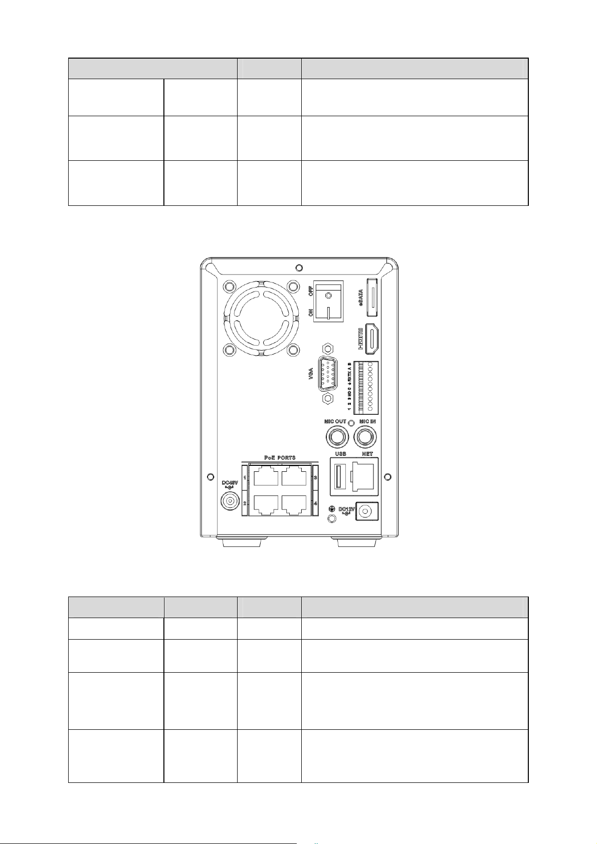
2.2.1 NVR7XXNS Series
The rear panel is shown as below. See Figure 2-4.
Figure 2-4
Please refer to the following sheet for detailed information.
Port Name Connection Function
USB port. Connect to USB mouse.
Network port 10M/100M/1000M self-adaptive Ethernet port.
Connect to the network cable.

13
Port Name Connection Function
RS232 232 debug
COM.
It is for general COM debug to configure IP
address or transfer transparent COM data.
HDMI High
Definition
Media
Interface
High definition audio and video signal output
port. It transmits uncompressed high definition
video and multiple-channel data to the HDMI
port of the display device.
VGA
VGA video
output port
VGA VGA video output port. Output analog video
signal. It can connect to the monitor to view
analog video.
1-16 Alarm input
port.
z There are four groups. The first group is
from port 1 to port 4, the second group is
from port 5 to port 8, the third group is
from 9 to 12, and the fourth group is from
13 to 16. They are to receive the signal
from the external alarm source. There are
two types; NO (normal open)/NC (normal
close).
z When your alarm input device is using
external power, please make sure the
device and the NVS have the same
ground.
Alarm input
port ground
end
Alarm input ground end.
NO1 to NO3
C1 to C3
3-ch alarm
output port
z 3 groups of alarm output ports. (Group 1:
port NO1~C1,Group 2:port NO2~
C2,Group 3:port NO3~C3)).Output
alarm signal to the alarm device. Please
make sure there is power to the external
alarm device.
z NO:Normal open alarm output port.
z C:Alarm output public end.
A RS485_A port. It is the cable A. You can
connect to the control devices such as speed
dome PTZ.
B
RS485 port
I/O port
RS485_B.It is the cable B. You can connect to
the control devices such as speed dome PTZ.
Power input
port
Input 12V DC.
Power button Power on/off button.
PoE PORTS Built-in Switch supports PoE function.
Power input
port
Switch power port. Input DC 48V.
14
Port Name Connection Function
VIDEO OUT
Video input
port
CVBS output
MIC IN Audio input
port
Bidirectional talk input port. It is to receive the
analog audio signal output from the devices
such as mike phone, pickup.
MIC OUT Audio output
port
Audio output port. It is to output the analog
audio signal to the devices such as the sound
box.
2.2.2 NVR6XXV Series
The rear panel is shown as below. See Figure 2-5.
Figure 2-5
Please refer to the following sheet for detailed information.
Port Name Connection Function
USB USB port. Connect to USB mouse.
NET Network port 10M/100M/1000M self-adaptive Ethernet port.
Connect to the network cable.
HDMI High
Definition
Media
Interface
High definition audio and video signal output
port. It transmits uncompressed high definition
video and multiple-channel data to the HDMI
port of the display device.
VGA
VGA video
output port
VGA VGA video output port. Output analog video
signal. It can connect to the monitor to view
analog video.

15
Port Name Connection Function
1-3 Alarm input
port 1-3.
z Alarm input port.
z When your alarm input device is using
external power, please make sure the
device and the NVS have the same
ground.
Alarm input
port ground
end
Alarm input ground end.
NO
C
Alarm output
port
z 3 groups of alarm output ports. (Group 1:
port NO1~C1,Group 2:port NO2~
C2,Group 3:port NO3~C3)).Output
alarm signal to the alarm device. Please
make sure there is power to the external
alarm device.
z NO:Normal open alarm output port.
z C:Alarm output public end.
A RS485_A port. It is the cable A. You can
connect to the control devices such as speed
dome PTZ.
B
RS485 port
I/O port
RS485_B.It is the cable B. You can connect to
the control devices such as speed dome PTZ.
Power input
port
Input 12V DC.
Power button Power on/off button.
PoE PORTS Built-in Switch supports PoE function.
Power input
port
Switch power port. Input DC 48V.
MIC IN Audio input
port
Bidirectional talk input port. It is to receive the
analog audio signal output from the devices
such as mike phone, pickup.
MIC OUT Audio output
port
Audio output port. It is to output the analog
audio signal to the devices such as the sound
box.
eSATA
eSATA port
External SATA port. It can connect to the
device of the SATA port. Please jump the HDD
when there is peripheral connected HDD.
2.2.3 NVR7XXN Series
The rear panel is shown as below. See Figure 2-6.

16
Figure 2-6
Please refer to the following sheet for detailed information.
Port Name Connection Function
Power button Power on/off button.
Power input
port
Input AC 220V power.
MIC IN Audio input
port
Bidirectional talk input port. It is to receive the
analog audio signal output from the devices
such as mike phone, pickup.
MIC OUT Audio output
port
Audio output port. It is to output the analog
audio signal to the devices such as the sound
box.
1-16 Alarm input
port 1-16.
There are four groups. The first group
is from port 1 to port 4, the second
group is from port 5 to port 8, the
third group is from 9 to 12, and the
fourth group is from 13 to 16. They
are to receive the signal from the
external alarm source. There are two
types; NO (normal open)/NC (normal
close).
When your alarm input device is
using external power, please make
sure the device and the NVS have
the same ground.
Ground end Alarm input ground end.
NO1 to NO5
C1 to C5
NC5
5-ch alarm
output port
z 5 groups of alarm output ports. (Group 1:
port NO1~C1,Group 2:port NO2~
C2,Group 3:port NO3~C3, Group 4:port
NO4~C4, Group 5: port NO5, C5,
NC5).Output alarm signal to the alarm
device. Please make sure there is power
to the external alarm device.
z NO: Normal open alarm output port.
z C: Alarm output public end.
z NC: Normal close alarm output port.
A RS485 port
I/O port
RS485_A port. It is the cable A. You can
connect to the control devices such as speed
dome PTZ.

17
Port Name Connection Function
B RS485_B.It is the cable B. You can connect to
the control devices such as speed dome PTZ.
CTRL 12V Controller 12V power output. It is to control the
on-off alarm relay output. It can be used to
control the device alarm output. At the same
time, it can also be used as the power input
source of some devices such as the alarm
detector.
+12V +12V power output port. It can provide the
power to some peripheral devices such as the
camera or the alarm device. Please note the
supplying power shall be below 1A.
Network port 10M/100M/1000M self-adaptive Ethernet port.
Connect to the network cable.
eSATA eSATA port External SATA port. It can connect to the
device of the SATA port. Please jump the HDD
when there is peripheral connected HDD.
USB port. Connect to USB mouse.
RS232 RS232 debug
COM.
It is for general COM debug to configure IP
address or transfer transparent COM data.
HDMI High Definition
Media
Interface
High definition audio and video signal output
port. It transmits uncompressed high definition
video and multiple-channel data to the HDMI
port of the display device.
VGA
VGA video
output port
VGA video output port. Output analog video
signal. It can connect to the monitor to view
analog video.
2.3 Alarm Connection
Please refer to the steps listed below.
z Connect the alarm input device to the alarm input port.
z Connect the alarm output device to the alarm output port. The NO and NC alarm output
device can connect to the NO/C/NC port. For the NO alarm device, please connect to the
NO/C ports. For the NC alarm device, please connect to the NC/C ports. Please note the
NO/C ports are for NO alarm device only.
z Open Web, and go to the Alarm setup interface to set the alarm input and output. The alarm
01 is corresponding to the first channel of the device I/O port and so on. Please set the
NO/NC type according to the high/low level the alarm input device generated when an alarm
occurred
z Set the alarm output on the Web. The alarm output 01 is corresponding to the first group of
alarm out put port.
2.4 Bidirectional talk
2.4.1 Device-end to PC-end

18
Device Connection
Please connect the speaker or the pickup to the first audio input port in the device rear panel.
Then connect the earphone or the sound box to the audio output port in the PC.
Login the Web and then enable the corresponding channel real-time monitor.
Please refer to the following interface to enable bidirectional talk.
Figure 2-7
Listening Operation
At the device end, speak via the speaker or the pickup, and then you can get the audio from the
earphone or sound box at the pc-end.
2.4.2 PC-end to the device-end
Device Connection
Connect the speaker or the pickup to the audio output port in the PC and then connect the
earphone or the sound box to the first audio input port in the device rear panel.
Login the Web and then enable the corresponding channel real-time monitor.
Please refer to the above interface (Figure 2-7) to enable bidirectional talk.
Listening Operation
At the PC-end, speak via the speaker or the pickup, and then you can get the audio from the
earphone or sound box at the device-end.
2.5 Mouse Operation
Please refer to the following sheet for mouse operation instruction.
When you have selected one menu item, left click mouse to view menu
content.
Modify checkbox or motion detection status.
Left click
mouse
Click combo box to pop up dropdown list
19
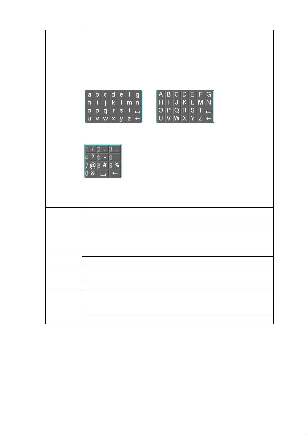
In input box, you can select input methods. Left click the corresponding button
on the panel you can input numeral/English character (small/capitalized).
Here ← stands for backspace button. _ stands for space button.
In English input mode: _stands for input a backspace icon and ← stands for
deleting the previous character.
In numeral input mode: _ stands for clear and ← stands for deleting the
previous numeral.
When input special sign, you can click corresponding numeral in the front
panel to input. For example, click numeral 1 you can input“/” , or you can click
the numeral in the on-screen keyboard directly.
Implement special control operation such as double click one item in the file
list to playback the video.
Double left
click mouse
In multiple-window mode, double left click one channel to view in full-window.
Double left click current video again to go back to previous multiple-window
mode.
In real-time monitor mode, pops up shortcut menu. Right click
mouse
Exit current menu without saving the modification.
In numeral input box: Increase or decrease numeral value.
Switch the items in the check box.
Press
middle
button
Page up or page down
Move
mouse
Select current control or move control
Select motion detection zone Drag mouse
Select privacy mask zone.
20
3 HDD Installation
For the first time install, please be aware that whether the HDDs have been installed.
Strongly recommended to use the HDDs which we suggest you to use (high speed HDD that
above 7200 rounds), we do not suggest you to use PC specified HDD.
You can refer to the User’s Manual for recommended HDD brand. Please use HDD of 7200rpm or
higher. Usually we do not recommend the PC HDD.
Please follow the instructions below to install hard disk.
All figures listed here for reference only.
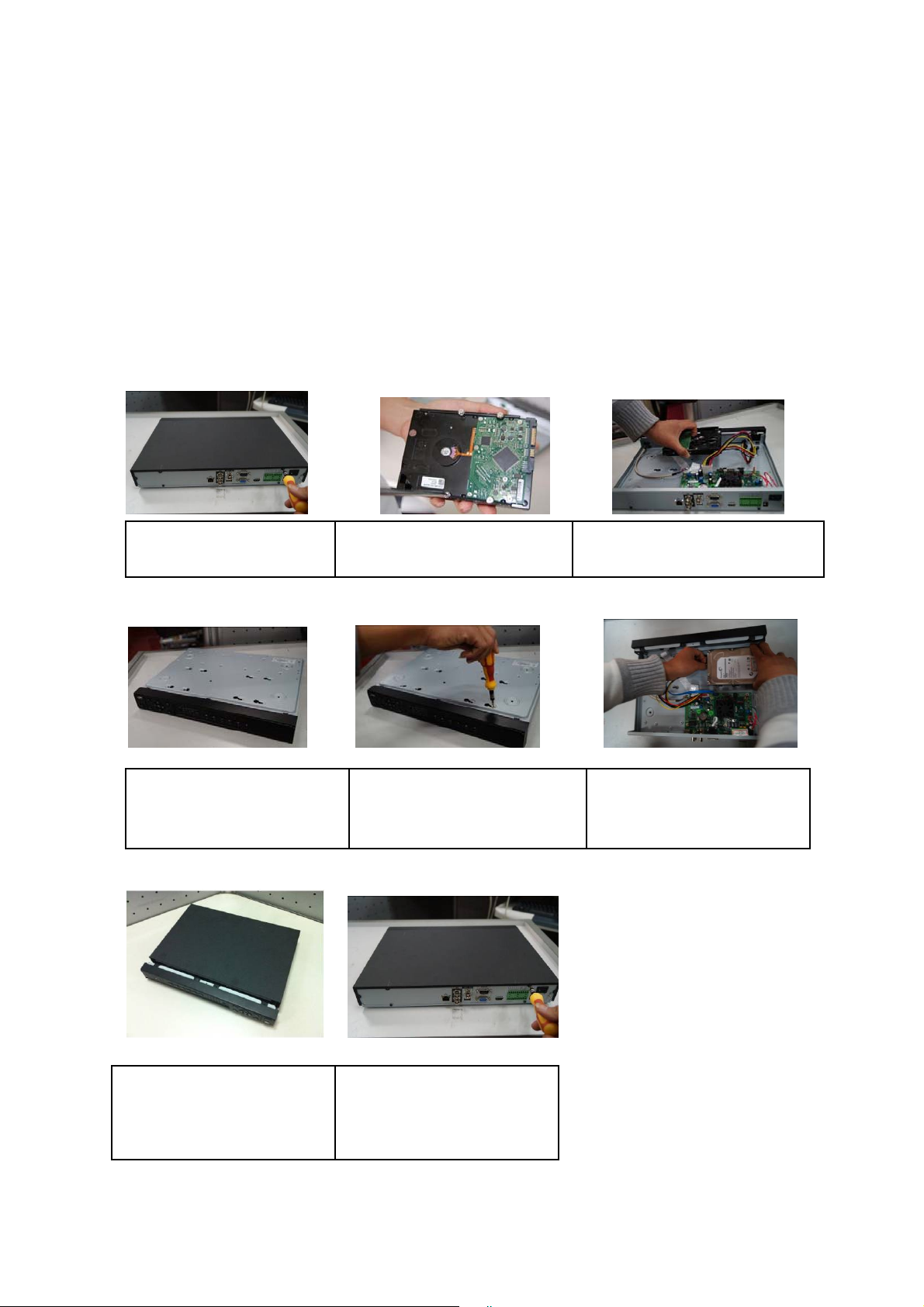
3.1 NVR7XXNS Series
1. Loosen the screws of the
u
pp
er cove
r
and side
p
anel.
2. Fix four screws in the HDD
(
Turn
j
ust three rounds
)
.
3. Place the HDD in accordance with
the four holes in the bottom.
4. Turn the device upside down
and then turn the screws in
firml
y
.
5. Fix the HDD firmly.
6. Connect the HDD cable and
power cable.
7. Put the cover in accordance
with the clip and then place the
upper cover back.
8. Secure the screws in the
rear panel and the side panel.
21
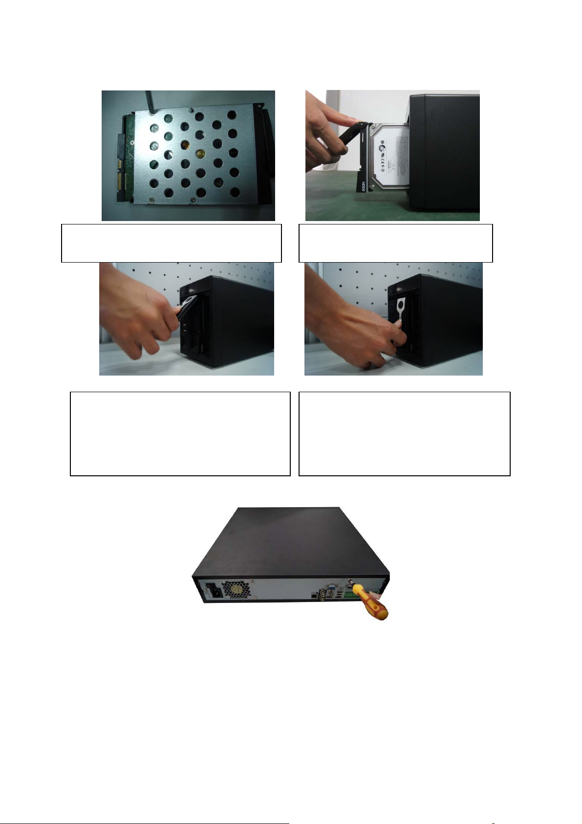
3.2 NVR6XXV Series
3.3 NVR7XXN Series
① Use the screwdriver to loose the screws of the rear panel and then remove the front cover.
①Use 4 screws to secure the HDD
②Put the HDD to the HDD box at the front.
③Pull the HDD knob up when you put the HDD
into the box in case the knob buckle may strike
the front panel.
④Put the knob back after you insert the HDD
to the SATA board.
 Loading...