

Page 1
1
Network Video Recorder User’s Manual
Applies to A/L/S series only
Page 2

2
Table of Contents
1 Features and Specifications ...........................................................................................................................9
1.1 Overview....................................................................................................................................................9
1.2 Features.....................................................................................................................................................9
1.3 Specifications..........................................................................................................................................10
2 Front Panel and Rear Panel .........................................................................................................................13
2.1 Front Panel..............................................................................................................................................13
2.1.1 A Series.............................................................................................................................................13
2.1.2 L Series .............................................................................................................................................13
2.1.3 S Series.............................................................................................................................................15
2.2 Rear Panel...............................................................................................................................................18
2.2.1 A Series.............................................................................................................................................18
2.2.2 L Series .............................................................................................................................................19
2.2.3 S Series.............................................................................................................................................21
2.3 Bidirectional talk .....................................................................................................................................23
2.3.1 Device-end to PC-end.....................................................................................................................23
2.3.2 PC-end to the device-end...............................................................................................................24
2.4 Mouse Operation....................................................................................................................................24
2.5 Remote Control.......................................................................................................................................25
3 HDD Installation..............................................................................................................................................28
3.1 A Series ...................................................................................................................................................28
3.2 L Series....................................................................................................................................................29
3.3 S Series ...................................................................................................................................................31
Page 3

3
4 Network Connection.......................................................................................................................................33
4.1 A Series Connection ..............................................................................................................................33
4.2 L Series Connection...............................................................................................................................33
4.3 S Series Connection ..............................................................................................................................34
5 GUI Operation.................................................................................................................................................36
5.1 Login.........................................................................................................................................................36
5.2 Right Click Menu ....................................................................................................................................37
5.3 Main Menu...............................................................................................................................................37
5.4 Search and Playback.............................................................................................................................38
5.5 Information...............................................................................................................................................40
5.5.1 HDD Information ..............................................................................................................................40
5.5.2 BPS....................................................................................................................................................41
5.5.3 Log .....................................................................................................................................................42
5.5.4 Version ..............................................................................................................................................42
5.5.5 Online Users.....................................................................................................................................43
5.6 Setting ......................................................................................................................................................43
5.6.1 General .............................................................................................................................................44
5.6.2 Schedule ...........................................................................................................................................45
5.6.3 RS232 ...............................................................................................................................................46
5.6.4 Network .............................................................................................................................................47
5.6.4.1 Advanced Setup .....................................................................................................................48
5.6.4.2 IP Filter.....................................................................................................................................48
5.6.4.3 PPPoE......................................................................................................................................48
5.6.4.4 NTP Setup ...............................................................................................................................49
5.6.4.5 DDNS Setup............................................................................................................................49
5.6.4.6 DNS ..........................................................................................................................................50
5.6.4.7 Network Storage.....................................................................................................................51
5.6.5 Alarm .................................................................................................................................................51
Page 4

4
5.6.6 PTZ ....................................................................................................................................................52
5.6.7 Display...............................................................................................................................................53
5.6.8 Default ...............................................................................................................................................54
5.7 Advanced.................................................................................................................................................55
5.7.1 HDD Management...........................................................................................................................55
5.7.2 Abnormity..........................................................................................................................................56
5.7.3 Alarm Output ....................................................................................................................................57
5.7.4 Manual Record.................................................................................................................................58
5.7.5 Account .............................................................................................................................................58
5.7.6 Auto Maintain ...................................................................................................................................59
5.7.7 TV Adjust...........................................................................................................................................59
5.7.8 Remote Device ................................................................................................................................60
5.8 Backup .....................................................................................................................................................61
5.8.1 Detect Device...................................................................................................................................61
5.8.2 Local Backup....................................................................................................................................62
5.8.3 Network Backup...............................................................................................................................63
5.9 Shutdown.................................................................................................................................................64
6 Quick Configuration Tool...............................................................................................................................65
6.1 Overview..................................................................................................................................................65
6.2 Operation .................................................................................................................................................65
7 Web ..................................................................................................................................................................68
7.1 General Introduction ..............................................................................................................................68
7.1.1 Preparation .......................................................................................................................................68
7.1.2 Log in.................................................................................................................................................68
7.2 Main Interface .........................................................................................................................................69
7.2.1 Monitor Channel Menu Tree ..........................................................................................................70
7.2.2 System Menu ...................................................................................................................................72
7.2.3 Monitor Window Switch ..................................................................................................................72
7.2.4 Preview Window Switch .................................................................................................................72
7.2.5 PTZ Control ......................................................................................................................................72
Page 5

5
7.2.6 Color and More Setup.....................................................................................................................75
7.3 Configuration...........................................................................................................................................75
7.3.1 System Information .........................................................................................................................75
7.3.1.1 Version Information ................................................................................................................76
7.3.1.2 HDD information .....................................................................................................................76
7.3.1.3 Log............................................................................................................................................76
7.3.2 System Configuration......................................................................................................................77
7.3.2.1 General Setup.........................................................................................................................77
7.3.2.2 Schedule..................................................................................................................................79
7.3.2.3 RS232 ......................................................................................................................................81
7.3.2.4 Network ....................................................................................................................................82
7.3.2.5 Alarm ........................................................................................................................................88
7.3.2.6 PTZ ...........................................................................................................................................90
7.3.2.7 Default & Backup....................................................................................................................91
7.3.3 Advanced..........................................................................................................................................91
7.3.3.1 HDD Management..................................................................................................................92
7.3.3.2 Alarm I/O..................................................................................................................................92
7.3.3.3 Record......................................................................................................................................93
7.3.3.4 Account ....................................................................................................................................94
7.3.3.5 Auto Maintenance ..................................................................................................................95
7.3.3.6 Abnormity.................................................................................................................................95
7.3.4 Additional Function..........................................................................................................................96
7.3.4.1 DNS ..........................................................................................................................................96
7.3.4.2 Remote Device .......................................................................................................................97
7.4 Search......................................................................................................................................................98
7.5 Alarm ......................................................................................................................................................100
7.6 About ......................................................................................................................................................101
7.7 Log out ...................................................................................................................................................102
8 FAQ ................................................................................................................................................................103
9 Appendix A HDD Capacity Calculation .....................................................................................................108
10 Appendix B Compatible SATA HDD......................................................................................................109
Page 6

6
11 Appendix C Compatible USB List..........................................................................................................110
12 Appendix D Compatible Displayer List.................................................................................................. 111
13 Appendix E No-IP DDNS ........................................................................................................................112
Page 7

7
Welcome
Thank you for purchasing our network video recorder!
This quick start guide is designed to be a reference tool for your system.
Please open the accessory bag to check the items one by one in accordance with the list below.
Contact your local retailer ASAP if something is missing or damaged in the bag.
Before your operation please read the follow ing instructi ons carefully.
z Installation environment
Keep away from extreme hot places and sources;
Avoid direct sunlight;
Keep away from extreme humid places;
Avoid violent vibration;
Do not put other devices on the top of the NVR;
Be installed in well ventilated place; do not block the vent.
z Accessories
Check the following accessories after opening the box:
z Please refer to the packing list in the box *
Component Name A Series L/S Series Quantity
NVR ■ ■ 1
7-pin SATA cable ■ ■ 1
Power cable ■ ■ 1
Network cable ■ ■ 1
Remote control □ ■ 1
Black optical mouse ■ ■ 1
Power adapter ■ □ 1
Quick start guide ■ ■ 1
Product warranty card ■ ■ 1
Product certificate
card
■ ■ 1
Page 8

8
CD ■ ■ 1
Plastic pad ■ ■ 4
Important
We assume no liability or responsibility for all the fires or electrical shock caused by improper
handling or installation.
We are not liable for any problems caused by unauthorized modifications or attempted repair.
Page 9

9
1 Features and Specifications
1.1 Overview
It is a high performance network video recorder. This series product support local preview, multiple-
window display, recorded file local storage, remote control and mouse shortcut menu operation, and
remote management and control function. All these functions support this series product to be used in
various situations.
This series product supports centre storage, front-end storage and client-end storage. The monitor zone
in the front-end can be set in anywhere. Working with other front-end devices such as IPC, NVS, this
series product can establish a strong surveillance network via the CMS. In the network system, there is
only one network cable from the monitor centre to the monitor zone in the whole network. There is no
audio/video cable from the monitor centre to the monitor zone. The whole project is featuring of simple
connection, low-cost, low maintenance work.
This series NVR can be widely used in many areas such as public security, water conservancy,
transportation and education.
1.2 Features
User
Management
• ·Each group has different management powers that can be edited freely.
Every user belongs to an exclusive group.
Storage
• Via corresponding setup (such as alarm setup and schedule setup), you
can backup related audio/video data in the network video recorder.
• Support Web record and record local video and storage the file in the
client end.
Alarm
• Respond to external alarm simultaneously (within 200MS), based on
user’s pre-defined relay setup, system can process the alarm input
correctly and prompt user by screen and voice (support pre-recorded
audio).
• Support central alarm server setup, so that alarm information can
remotely notify user automatically. Alarm input can be derived from
various connected peripheral devices.
• Alert you via EMAIL.
Page 10

10
Network
Monitor
• Through network, sending audio/video data compressed by IPC or NVS
to client-ends, then the data will be decompressed and display. If
bandwidth is big enough, latency is less than 500ms
• Support max 10 connections
• Transmit audio/video data by HTTP, TCP, UDP, MULTICAST, RTP/RTCP
and etc.
• Transmit some alarm data or alarm info by SMTP.
• Support WEB access in WAN.
Window Split
• Adopt the video compression and digital process to show several
windows in one monitor. Support 1/4/9/16-window display.
Record
• Support schedule record function. Save the recorded files in the HDD, client-
end PC, or network storage server. You can search or playback the saved
files at the local-end or via the Web.
Backup
• Support network backup, USB record backup function, the recorded files
can be saved in network storage server, peripheral USB device, burner and
etc.
Network
Management
• Supervise NVR configuration and control power via Ethernet.
• Support management via WEB.
Peripheral
Equipment
Management
• Support peripheral equipment management such as protocol setup and
port connection.
• Support transparent data transmission through RS232/RS485.
Auxiliary
• Support switch between NTSC and PAL.
• Support real-time system resources information and running statistics
display.
• Support log file.
• Local GUI output. Shortcut menu operation via mouse.
• IR control function. Shortcut menu operation via remote control.
• Support IPC or NVS remote video preview and control.
1.3 Specifications
Specification
Parameter
A Series L Series S Series
System
Resources
Support max 16-channel record and 10 network users operation at the same time.
Operation
System
Embedded Linux real-time operation system
Operation
Interface
WEB/Local GUI
Video
Compression
H.264/MPEG4
Page 11

11
Encode
Capacity
For H.264, it max supports 4*D1. For MPEG4, it max supports 1*720p.
Audio
Compression
G.711a
Video Output
1-channel VGA analog video output.
Video Input
4/8/16-ch network compression digital video input
HDMI
1-ch HDMI output.
Audio Input
N/A 1-ch bidirectional audio
input
1-ch bidirectional audio
input
Audio Output
1-channel bidirectional talk output.
Frame Rate
Real-time mode:
NTSC 1f/s-30f/s for each channel (Adjustable).
PAL 1f/s-25f/s for each channel (Adjustable)
Window Split
4/8/16-window
Multiplechannel
Playback
Max 4-channel playback.
Alarm Input
4/8/16-ch alarm input.
3-ch alarm output 6-ch alarm output 6-ch alarm output
Alarm Output
Relay output. Relay (DC 30V 1A,AC 125V 0.5A(Activation output))
Including one controllable DC +12V output.
2 built-in SATA port s 4 built-in SATA ports 8 built-in SATA ports
Storage
N/A 1 peripheral eSATA port 1 peripheral eSATA port
RS232 Port
One RS232 port to debug transparent COM data.
RS485 port
One RS485 port to control PTZ. Support various protocols.
USB Port
2 peripheral USB ports. 2 peripheral USB ports. 1 peripheral USB port.
Network
Connection
One RJ45 10/100M self-adaptive Ethernet port.
Power Port
One power port, power
adapter. Input DC 12V.
One power port, AC90 ~
264V 50+2% Hz.
One power port, AC90 ~
264V 50+2% Hz.
Power Button
One power button in the rear panel.
Page 12

12
Power Button
One power button in the front panel.
IR Remote
Control
Receiver
N/A One IR remote control
receiver in the front panel.
One IR remote control
receiver in the front panel.
Clock
Built-in clock.
16 record status indication
lights
One power status
indication light.
One alarm status
indication light.
One network status
indication light.
One HDD status indication
light.
16 record status indication
lights
One system running status
indication light.
One remote control
indication light.
16 record status indication
lights
One system running status
indication light.
One remote control
indication light.
Indication
Light
Power
Consumption
<12W(Excluding HDD) <40W(Excluding HDD) <40W(Excluding HDD)
Working
Temperature
0℃~+50℃
Working
Humidity
10℅-90℅
Air pressure
86kpa-106kpa
Dimension 440mm*300mm*42.6mm 440mm*440mm*60mm 440mm*460mm*89mm
Weight
5.5~6.5KG(Excluding HDD)
Installation
Desk installation/Rack installation
Page 13
13
2 Front Panel and Rear Panel
2.1 Front Panel
2.1.1 A Series
The A series NVR front panel is shown as below. See Figure 2-1.
Figure 2-1
Please refer to the following sheet for detail information.
Icon Name
Power button. It is to boot up or
shut down the device.
Power status indication light
The light becomes red when the
power connection is normal.
Alarm status indication light
The light becomes red when
there is an input alarm.
Network status indication light
The light becomes red when
network connection is abnormal.
HDD status indication light.
The light becomes red when
HDD error occurs.
~
Record status indication light
The light becomes green when
corresponding channel is
recoding.
2.1.2 L Series
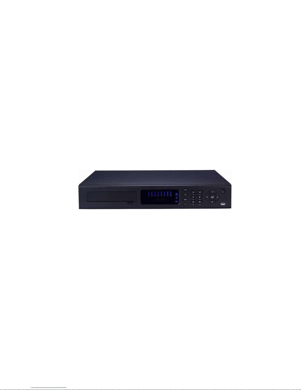
The L series NVR front panel is shown as in Figure 2-2.
Figure 2-2
Please refer to the following sheet for detail information.
Page 14

14
Icon Name Function
CD-ROM Pop-up or put in the CD-ROM
IR
IR remote control
receive port
It is to receive the IR signal from the remote control.
1~16
Record status indication
light
When there is a channel is recording, the corresponding
light becomes green.
Status
System running status
indication light
The light becomes red when system is running properly.
ACT
Remote control key
indication light
The light becomes red when the remote control address
and the device address is the same. The red light
becomes flash when you press the key in the remote
control.
Power
Power status indication
light
The light becomes red when the power connection is
OK.
Esc Cancel
Go to previous menu, or cancel current operation.
When playback, click it to restore real-time monitor
mode.
One-window monitor mode, click this button to display
assistant function: PTZ control and image color.
After you entered the PTZ control interface, click it to
switch PTZ control menu.
Backspace function: in numeral control or text control,
press it for 1.5seconds to delete the previous character
before the cursor.
In motion detection setup, working with Fn and direction
keys to realize setup.
In HDD information interface, click it to view HDD record
time and other information (menu prompt)
Fn Auxiliary button
Realize other special functions.
Shift Switch
In textbox, click this button to switch between numeral,
English(Small/Capitalized),donation and etc.
Rec Record
Manually stop/start recording, working with direction
keys or numeral keys to select the recording channel.
Reverse/Pause/6
In normal playback or pause mode, click this button to
reverse playback
In reverse playback, click this button to pause playback.
In text mode, input number 6 (English character M/N/O)
Play/Pause /5
In normal playback click this button to pause playback
In pause mode, click this button to resume playback.
In text mode, input number 5(English character J/K/L).
Fast play/7
Various fast speeds and normal playback.
In text mode, input number 7 (English character
Page 15
15
Icon Name Function
P/Q/R/S).
Slow play/8
Multiple slow play speeds or normal playback.
In text mode, input number 8 (English character T/U/V).
Play previous/0
In playback mode, playback the previous video
In text mode, input number 0.
Play Next/9
In playback mode, playback the next video
In text mode, input number 9 (English character
W/X/Y/Z)
Up/1
Down /4
Increase/decrease numeral.
Assistant function such as PTZ
menu.
In text mode, input number 1/4
(English character G/H/I)
Left /2
Right /3
Shift current
activated control,
jumping to
up/down/left/right.
When playback, click these
buttons to control playback bar.
In text mode, input number
2(English character A/B/C)
/3(English character D/E/F)
Confirm
Confirm current operation
Go to default button
Go to menu
Power
Power button, press this button to boot up or shut down
NVR.
USB port
To connect USB storage device, USB mouse.
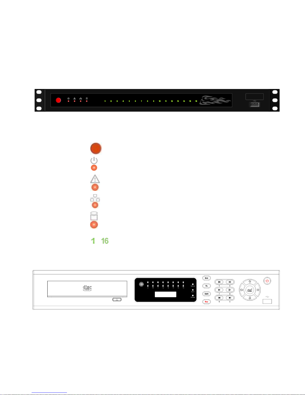
2.1.3 S Series
The S series NVR front panel is shown as in Figure 2-3.
Figure 2-3
Please refer to the following sheet for detail information.
Icon Name Function
1~16
Record status
indication light
When there is a recording channel, the
corresponding light becomes green.
ACT
Remote control key The light becomes red when the device receives the
Page 16

16
Icon Name Function
indication light IR signal from the remote control.
Status
System running status
indication light
The light becomes red when system is running
properly.
PWR
Power status
indication light
The light becomes red when the power connection is
OK.
IR
IR remote control
receive port
It is to receive the IR signal from the remote control.
Number 0 to 9.
Input number or switch the channel.
For number more than
10
When you channel number is more than 9, please
click this button and then input the number you
desire.
Shuttle(outer ring)
In real-time monitor mode it works as left/right directio
n
key.
Playback mode, counter clockwise to forward and
clock wise to backward
Jog(inner dial)
Up/down direction key.
Playback mode, turn the inner dial to realized frame
frame playback. (Only applies to some versions.)
Slow play/8
Multiple slow play speeds or normal playback.
In text mode, input number 8 (English character
T/U/V).
Fast play/7
Various fast speeds and normal playback.
Page 17

17
Icon Name Function
In text mode, input number 7 (English character
P/Q/R/S).
Reverse/Pause/6
In normal playback or pause mode, click this button
to reverse playback
In reverse playback, click this button to pause
playback.
In text mode, input number 6 (English character
M/N/O)
Play/Pause /5
In normal playback click this button to pause
playback
In pause mode, click this button to resume playback.
In text mode, input number 5(English character
J/K/L).
Play previous/0
In playback mode, playback the previous video
In text mode, input number 0.
Play Next/9
In playback mode, playback the next video
In text mode, input number 9 (English character
W/X/Y/Z)
Esc Cancel
Go to previous menu, or cancel current operation.
When playback, click it to restore real-time monitor
mode.
Enter Confirm
Confirm current operation
Go to default button
Go to menu
One-window monitor mode, click this button to
display assistant function: PTZ control and image
color.
After you entered the PTZ control interface, click it to
switch PTZ control menu.
Backspace function: in numeral control or text
control, press it for 1.5seconds to delete the previous
character before the cursor.
In motion detection setup, working with Fn and
direction keys to realize setup.
In HDD information interface, click it to view HDD
record time and other information (menu prompt)
Fn Auxiliary button
Realize other special functions.
Rec Record
Manually stop/start recording, working with direction
keys or numeral keys to select the recording channel.
Mult Window switch
Switch monitor window to single-window or multiplewindow.
Up/1
Shift current
Increase/decrease numeral.
Page 18
18
Icon Name Function
Down/4
Assistant function such as PTZ
menu.
In text mode, input number 1/4
(English character G/H/I)
Left/2
Right/3
activated control,
jumping to
up/down/left/right.
When playback, click these
buttons to control playback bar.
In text mode, input number
2(English character A/B/C)
/3(English character D/E/F)
Power
Power button, press this button to boot up or shut
down NVR.
USB port
To connect USB storage device, USB mouse.
2.2 Rear Panel
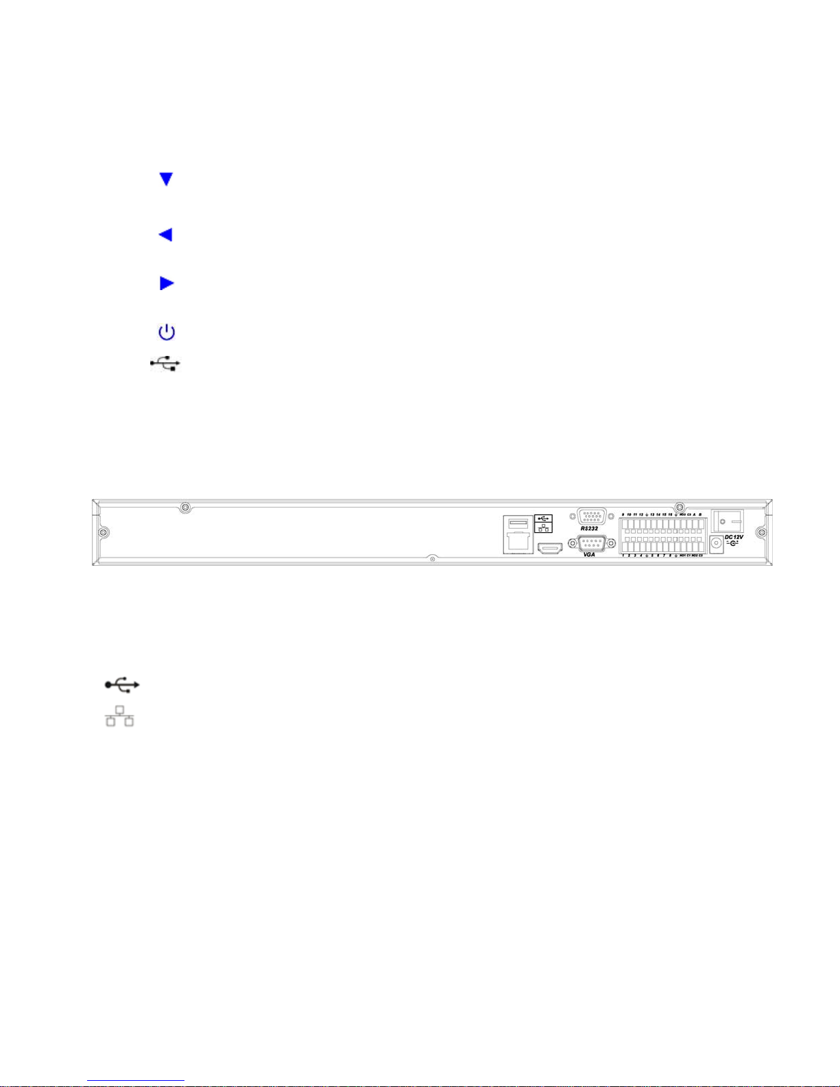
2.2.1 A Series
The A series NVR real panel is shown as in Figure 2-4.
Figure 2-4
Please refer to the following sheet for detailed information.
Port Name Connection Function
USB port. Connect to USB mouse.
Network port 10M/100M self-adaptive Ethernet port. Connect
to the network cable.
RS232 232 debug
COM.
It is for general COM debug to configure IP
address or transfer transparent COM data.
VGA VGA video
output port
VGA VGA video output port. Output analog video
signal. It can connect to the monitor to view
analog video.
1~16
Alarm input port.
1~16
I/O port
z Four groups of alarm input ports. The first
group is from port 1 to port 4, the second
group is from port 5 to port 8, the third
group is from 9 to 12, and the fourth group
is from 13 to 16. They are to receive the
signal from the external alarm source.
There are two types; NO (normal
Page 19

19
Port Name Connection Function
open)/NC (normal close).
z When your alarm input device is using
external power, please make sure the
device and the NVR have the same
ground.
Alarm input port
ground end
Alarm input ground end.
NO1~NO3
C1~C3
3-ch alarm
output port
z 3 groups of alarm output ports. (Group 1:
port NO1~C1,Group 2:port NO2~
C2,Group 3:port NO3~C3)).Output
alarm signal to the alarm device. Please
make sure there is power to the external
alarm device.
z
NO:Normal open alarm output port.
z C:Alarm output public end.
A RS485_A port. It is the cable A. You can
connect to the control devices such as speed
dome PTZ.
B
RS485
communication
port
RS485_B.It is the cable B. You can connect to
the control devices such as speed dome PTZ.
Power port Input 12V DC.
Power button Power on/off button.
2.2.2 L Series
The L series rear panel is shown as below. See Figure 2-5.
Figure 2-5
Please refer to the following sheet for detailed information.
Port Name Connection Function
Power button Power on/off button.
Power input
port
Input AC 220
Page 20

20
Port Name Connection Function
MIC OUT Audio output
port
RCA Audio output port. Output analog audio signal
to the devices such as sound box.
MIC IN Audio input port RCA
Bidirectional talk input port. Receive the analog
signal from the devices such as speaker or
pickup.
1~16
Alarm input port.
1~16
z Four groups of alarm input ports. The first
group is from port 1 to port 4, the second
group is from port 5 to port 8, the third
group is from 9 to 12, and the fourth group
is from 13 to 16. They are to receive the
signal from the external alarm source.
There are two types; NO (normal
open)/NC (normal close).
z When your alarm input device is using
external power, please make sure the
device and the NVR have the same
ground.
Ground end Alarm input ground end.
NO1~NO5
C1~C5
NC5
Alarm output
port 1~5
z
5 groups of alarm output ports. (Group 1:
port NO1~C1,Group 2:port NO2~C2,Group
3:port NO3~C3.group 4: port NO4~C4、
Group 5:port NO5、C5、NC5).Output
alarm signal to the alarm device. Please
make sure there is power to the external
alarm device.
z
NO:Normal open alarm output port.
z
C:Alarm output public end.
z
NC: Normal close alarm output port.
A RS485_A port. It is the cable A. You can
connect to the control devices such as speed
dome PTZ.
B
RS485 port
RS485_B.It is the cable B. You can connect to
the control devices such as speed dome PTZ.
CTRL 12V Controllable 12V power output. It is to control
the on-off relay output. You can use it to enable
device alarm function.
It can also be used as the power input for some
alarm devices such as the smoke detector.
+12V
I/O port
+12V power output port. It is to provide the
Page 21

21
Port Name Connection Function
power to the peripheral devices such as
camera or alarm device. The connected device
current shall be less than 1A.
Network port 10M/100M self-adaptive Ethernet port. Connect
to the network cable.
eSATA eSATA port The external SATA port. It can be connected to
the peripheral devices of SATA port.
Please pay attention to the HDD jumper when
you connect the external HDD.
USB port. Connect to USB mouse.
RS232 232 debug
COM.
It is for general COM debug to configure IP
address or transfer transparent COM data.
HDMI High definition
multimedia
interface
High definition video signal output port.
Transmit the clear video and multiple-track
data (Uncompressed)to the device of
HDMI(High definition media interface)
VGA VGA video
output port
VGA VGA video output port. Output analog video
signal. It can connect to the monitor to view
analog video.
2.2.3 S Series
The S series NVR rear panel is shown as in Figure 2-6.
Figure 2-6
Please refer to the following sheet for detailed information.
Port Name Connection Function
Power button Power on/off button.
Power input
port
Input AC 220
Page 22

22
Port Name Connection Function
MIC OUT Audio output port RCA Audio output port. Output analog audio signal to
the devices such as sound box.
MIC IN Audio input port RCA Bidirectional talk input port. Receive the analog
signal from the devices such as speaker or
pickup.
1~16
Alarm input port.
z 4 groups of alarm output ports. (Group 1:
port 1~4,Group 2:Port 5~8,Group 3:
port 9~12,Group 4:port 13~16).Output
alarm signal to the alarm device. Please
make sure there is power to the external
alarm device.
z When your alarm input device is using
external power, please make sure the
device and the NVR have the same ground.
Alarm input port
ground end
z Alarm input ground end.
NO1 to NO5
C1 to C5
NC5
Alarm output port
1~5
z
5 groups of alarm output ports. (Group 1:port
NO1~C1,Group 2:port NO2~C2,Group
3:port NO3~C3.group 4 port NO4~C4、
Group 5:port NO5、C5、NC5).Output alarm
signal to the alarm device. Please make sure
there is power to the external alarm device.
z
NO:Normal open alarm output port.
z
C:Alarm output public end.
z NC: Normal close alarm output port.
A RS485_A port. It is the cable A. You can
connect to the control devices such as speed
dome PTZ.
B
RS485 port
I/O port
RS485_B.It is the cable B. You can connect to
the control devices such as speed dome PTZ.
CTRL 12V Controllable 12V power output. It is to control
the on-off relay output. You can use it to enable
device alarm function.
It can also be used as the power input for some
alarm devices such as the smoke detector.
+12V +12V power output port. It is to provide the
power to the peripheral devices such as camera
or alarm device. The connected device current
Page 23

23
Port Name Connection Function
shall be less than 1A.
Network port 10M/100M self-adaptive Ethernet port. Connect
to the network cable.
eSATA eSATA port The external SATA port. It can be connected to
the peripheral devices of SATA port.
Please pay attention to the HDD jumper when
you connect the HDD.
USB port. Connect to USB mouse.
RS232 232 debug COM. It is for general COM debug to configure IP
address or transfer transparent COM data.
HDMI High definition
multimedia
interface
VGA VGA video output
port
VGA VGA video output port. Output analog video
signal. It can connect to the monitor to view
analog video.
Power button Power on/off button.
2.3 Bidirectional talk
2.3.1 Device-end to PC-end
Device Connection
Please connect the speaker or the pickup to the first audio input port in the device rear panel. Then
connect the earphone or the sound box to the audio output port in the PC.
Login the Web and then enable the corresponding channel real-time monitor.
Please refer to the following interface to enable bidirectional talk.
Page 24

24
Figure 2-7
Listening Operation
At the device end, speak via the speaker or the pickup, and then you can get the audio from the
earphone or sound box at the pc-end.
2.3.2 PC-end to the device-end
Device Connection
Connect the speaker or the pickup to the audio output port in the PC and then connect the earphone or
the sound box to the first audio input port in the device rear panel.
Login the Web and then enable the corresponding channel real-time monitor.
Please refer to the above interface (
Figure 2-7) to enable bidirectional talk.
Listening Operation
At the PC-end, speak via the speaker or the pickup, and then you can get the audio from the earphone
or sound box at the device-end.
2.4 Mouse Operation
Please refer to the following sheet for mouse operation instruction.
When you have selected one menu item, left click mouse to view menu
content.
Modify checkbox or motion detection status.
Left click
mouse
Click combo box to pop up dropdown list
Page 25
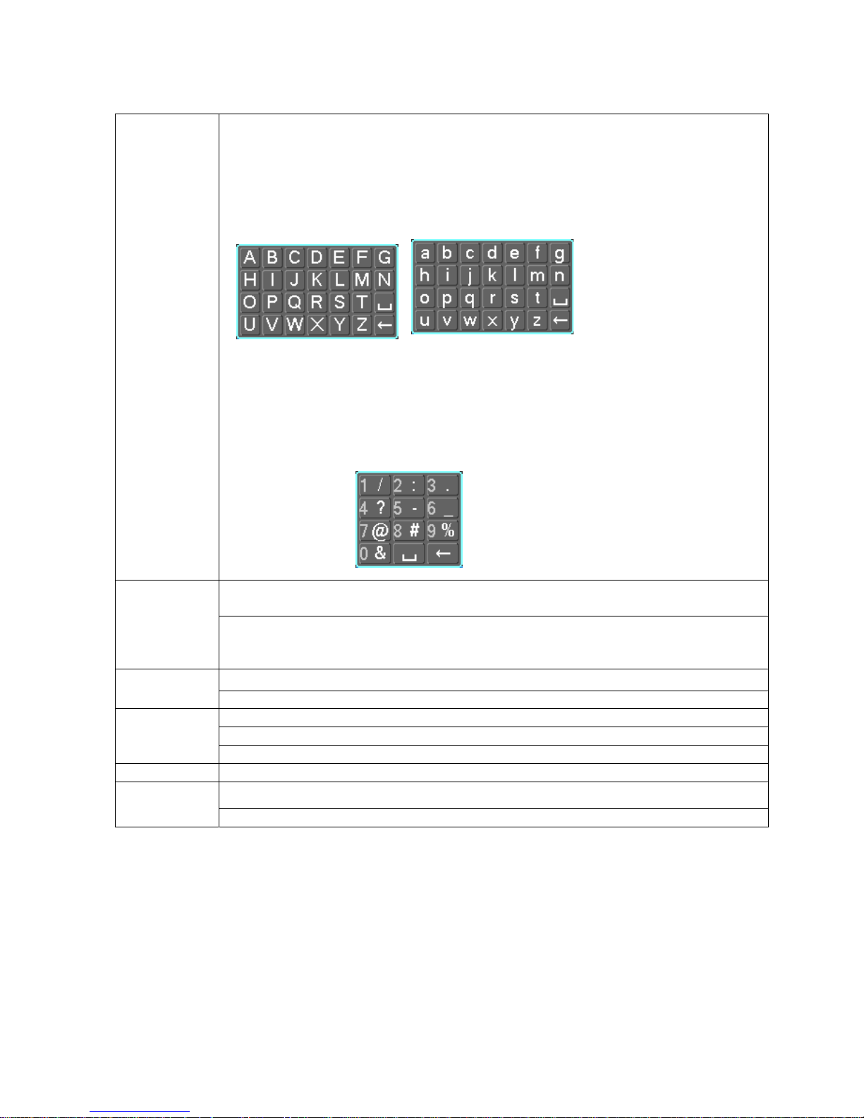
25
In input box, you can select input methods. Left click the corresponding button
on the panel you can input numeral/English character (small/capitalized). Here
← stands for backspace button. _ stands for space button.
In English input mode: _stands for input a backspace icon and ← stands for
deleting the previous character.
In numeral input mode: _ stands for clear and ← stands for deleting the
previous numeral.
When input special sign, you can click corresponding numeral in the front
panel to input. For example, click numeral 1 you can input“/” , or you can click
the numeral in the on-screen keyboard directly.
Implement special control operation such as double click one item in the file list
to playback the video.
Double left
click mouse
In multiple-window mode, double left click one channel to view in full-window.
Double left click current video again to go back to previous multiple-window
mode.
In real-time monitor mode, pops up shortcut menu. Right click
mouse
Exit current menu without saving the modification.
In numeral input box: Increase or decrease numeral value.
Switch the items in the check box.
Press
middle
button
Page up or page down
Move mouse Select current control or move control
Select motion detection zone Drag mouse
Select privacy mask zone.
2.5 Remote Control
The remote control interface is shown as in 282H282H282HFigure 2-4X.
Please note remote control is not our standard accessory and it is not included in the accessory bag.
Page 26

26
Figure 2-1
Serial Number Name Function
1 Address Click it to input device serial
number, so that you can control it.
2 Multiple-window switch Switch between one-window and
multiple-window.
0-9 number key Input password, channel or switch
channel.
Shift is the button to switch the input
method.
In textbox, click this button to switch
between numeral,
English(Small/Capitalized),donation,
Chinese
and etc.
In textbox, click this button to switch
between numeral, English
(Small/Capitalized),donation,
Chinese and etc.
Open/close tour
3
If your channel number is more than
10, please click this button and then
input the corresponding number.
4 Record Enable or disable record function
manually. In record control menu,
working with direction keys to select
record channel.
Page 27

27
5 Auxiliary key In 1-ch monitor mode: pop up
assistant function:PTZ control and
Video color
Confirm current operation
Go to the default button.
6 Confirm /menu key
Go to the menu.
Go back to the previous menu or
cancel current function menu (Close
the upper interface or control.)
7 Cancel
In playback mode, play the previous
file.
Activate current control, modify
setup.
Increase/decrease numeral.
S、T
Up/down
Assistant function such as PTZ
menu.
Shift current activated control.
8
W、X
Left/right
When playback, click these buttons
to control playback bar.
9 Forward Various forward speeds and normal
speed playback.
10 Previous Please refer to the previous in the
front panel.
11 Backward Various backward speeds and
normal speed playback.
12 Stop Stop record.
13 Next In playback mode, playback the
next video
14 Slow play Multiple slow play speeds or normal
playback
Reverse playback or paused mode,
click this button to realize
normal playback.
In normal playback click this button
to pause playback.
In pause mode, click this button to
resume playback.
15 Play/Pause
In real-time monitor mode, click this
button to enter video search menu.
16 Fast play Various fast speeds and normal
playback.
Page 28
28
3 HDD Installation
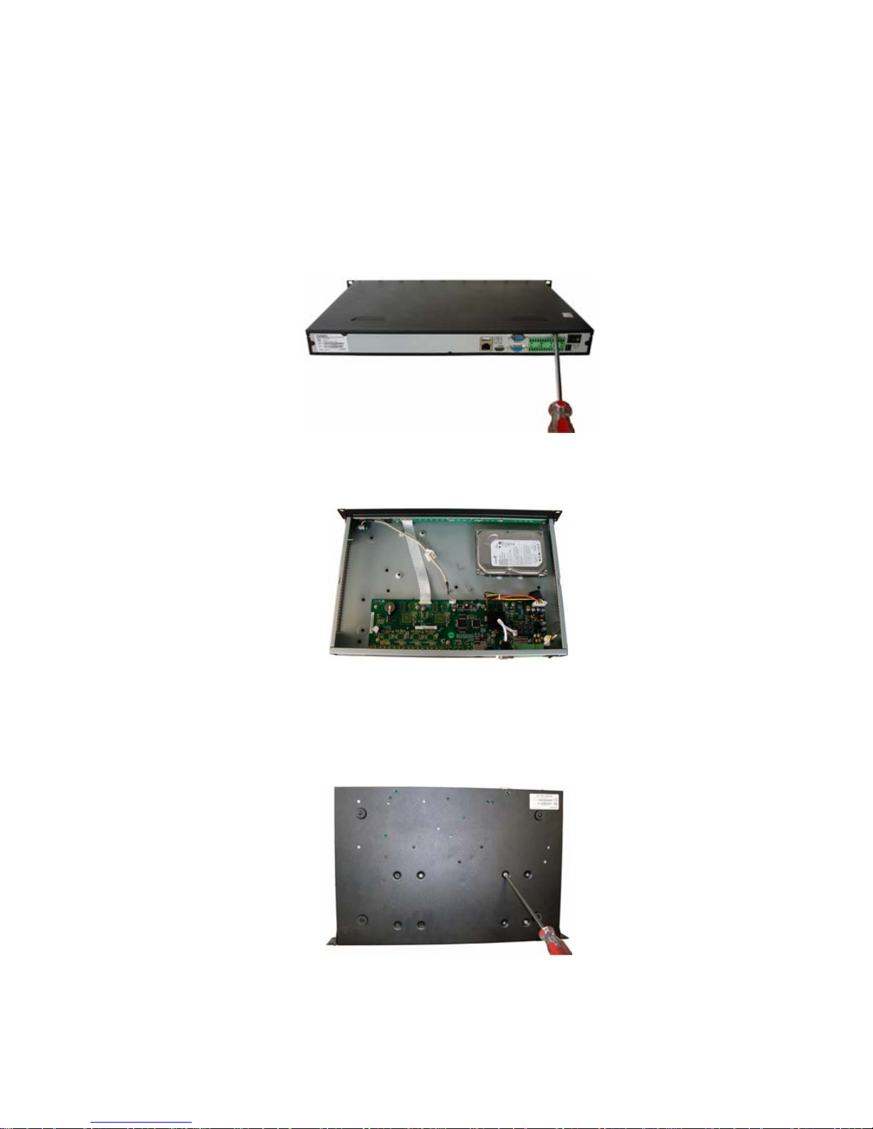
3.1 A Series
Pleas follow the steps listed below to install the HDD.
Use the screwdriver to loose the screws in the rear panel and the remove the front cover. See
238HFigure
3-1
Figure 3-1
Place the HDD in accordance with the four holes in the device chassis. See
239HFigure 3-2.
Figure 3-2
After you fix the HDD in the chassis manually, please turn the device and the HDD up for 90 degrees,
you can use the screwdriver to fix the four screws in the bottom of the chassis to secure the HDD. See
240HFigure 3-3.
Figure 3-3
Page 29
29
After you fix the HDD, please connect the data cable to the main board first and then connect the power
cable to the main board. See
241HFigure 3-4.
Figure 3-4
Please put the cover back and then fix the screws in the rear panel. See
242HFigure 3-5.
Figure 3-5
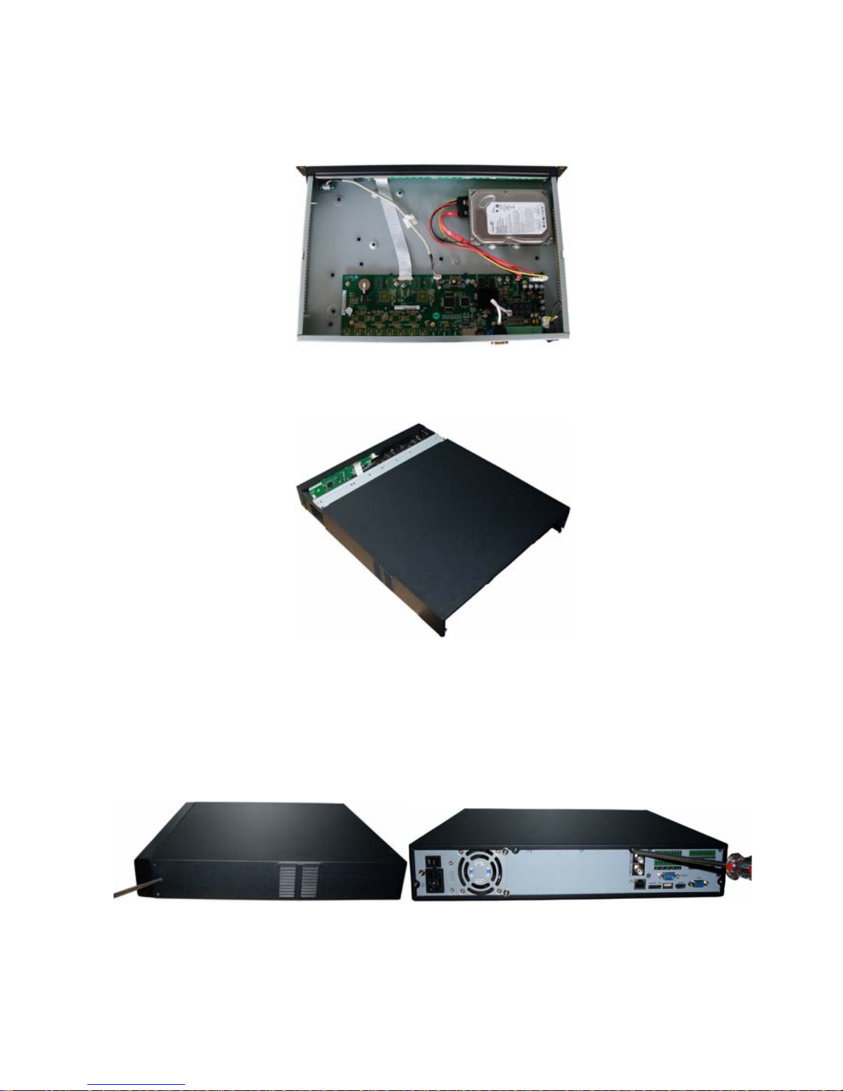
3.2 L Series
Use the screwdriver to loose the screws in the rear panel and the side panel, and then remove the front
cover. See
243HFigure 3-1
Figure 3-6
Place the HDD on the HDD bracket in accordance with the four holes in the device chassis. Use the
Page 30
30
screwdriver to secure the HDD in the HDD bracket. See
244HFigure 3-7.
Figure 3-7
Connect the HDD data cable to the main board and HDD port respectively. Loosen the power cable in
the chassis and then connect the power cable to the other port of the HDD. See
245HFigure 3-8.
Figure 3-8
After you fix the HDD, please connect the data cable to the main board first and then connect the power
cable to the main board. See
246HFigure 3-9.
Figure 3-9
Please put the cover back and then fix the screws in the rear panel and the side panel. See
247HFigure 3-10.
Page 31

31
Figure 3-10
3.3 S Series
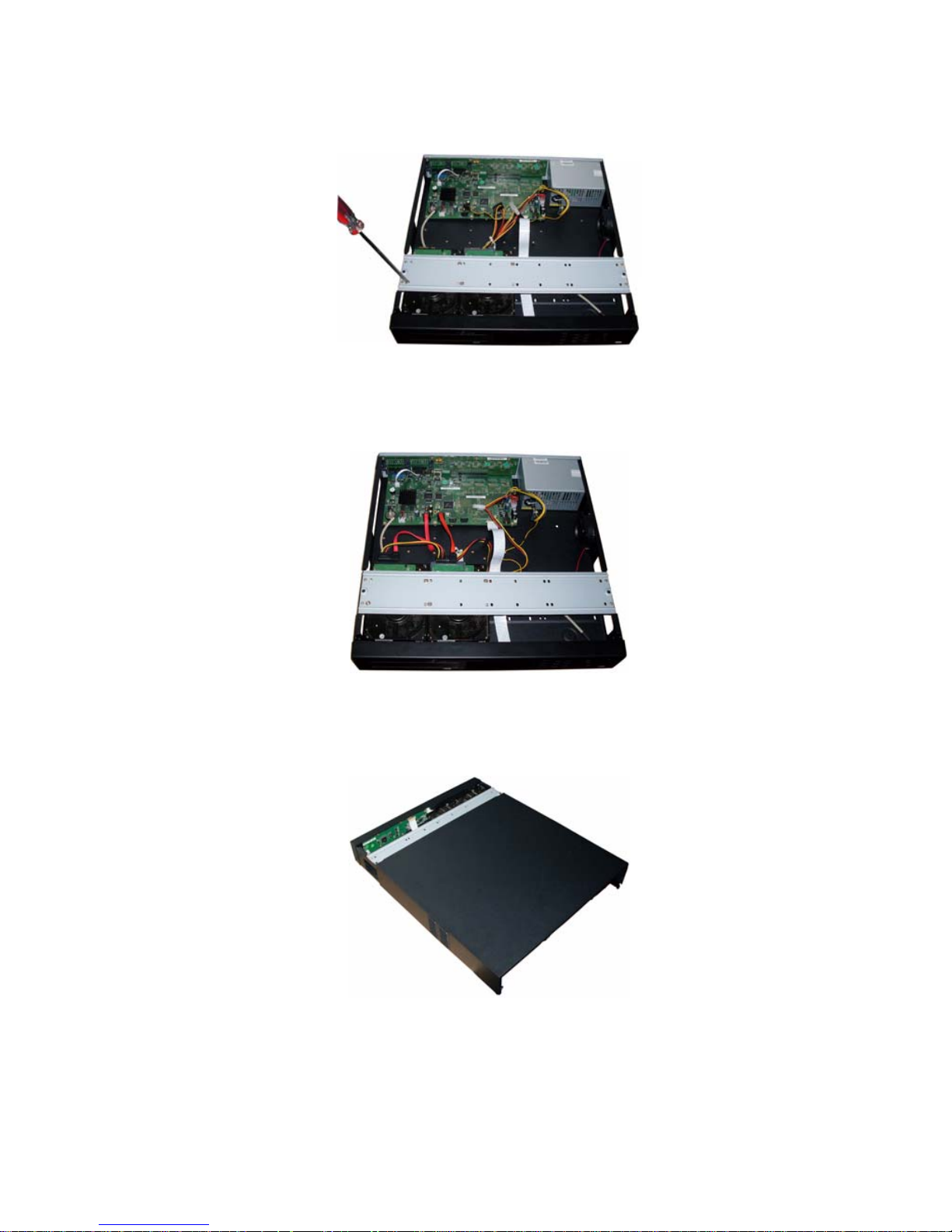
Pleas follow the steps listed below to install the HDD.
Use the screwdriver to loose the screws in the rear panel and then remove the front cover. See
248HFigure
3-11.
Figure 3-11
Place the HDD on the HDD bracket in accordance with the four holes in the device chassis. Use the
screwdriver to secure the HDD in the HDD bracket. See
249HFigure 3-12.
Figure 3-12
Connect the HDD data cable to the main board and HDD port respectively. Loosen the power cable in
the chassis and then connect the power cable to the other port of the HDD. See
250HFigure 3-13.
Page 32

32
Figure 3-13
Please put the cover back and then fix the screws in the rear panel. See
251HFigure 3-14.
Figure 3-14
Important
Before you replace the HDD, please make sure you have shut down the device and unplug the power
cable!
Page 33

33
4 Network Connection
4.1 A Series Connection
Please refer to the following figure for A series connection. See 252HFigure 4-1.
Figure 4-1
4.2 L Series Connection
Please refer to the following figure for L series connection. See 253HFigure 4-2.
Page 34

34
Figure 4-2
4.3 S Series Connection
Please refer to the following figure for S series connection. See 254HFigure 4-3.
Page 35

35
Figure 4-3
Page 36

36
5 GUI Operation
Connect the device to the monitor, insert the mouse and connect the power cable. Push the
on/off button in the rear panel and then you can see the analog video output. You can use the
mouse to implement some simple GUI operation. Please refer to the following chapter for detail
information. All the operations listed below are based on our 16-ch series device.
5.1 Login
After device booted up, the system is in multiple-channel display mode. See 255HFigure 5-1.
You can overlay the corresponding date, time and channel name on each screen. You can refer
to the following sheet for channel record or alarm status information.
Figure 5-1
Right click mouse, you can see the login interface. Please input user name and password. See
256HFigure 5-2.
System consists of four accounts:
z Username: admin. Password: admin.
z Username: 888888. Password: 888888.
z Username: 666666. Passwords: 666666.
z Username: default. Password: default.
You can use USB mouse to input. Click
to switch between numeral, English character
(small/capitalized) and denotation.
Note:
For security reason, please modify password after you first login.
Within 30 minutes, three times login failure will result in system alarm and five times login failure
will result in account lo
1
Recording status
3
Video loss
2
Motion detection
4
Camera lock
Page 37

37
Figure 5-2
5.2 Right Click Menu
After you logged in the device, right click mouse, you can see the short cut menu. Please see
257HFigure 5-3.
Here you can set local playback window, PTZ control, video color, search records, remote device
and etc. The local playback window includes 1/4/9/16. You can set the detail channel amount in
1/4-window.
Figure 5-3
5.3 Main Menu
After you logged in, the system main menu is shown as below. See 258HFigure 5-4. There are total six
icons: search, Information, setting, backup, advanced and shutdown. Move the cursor to highlight
the icon, then double click mouse to enter the sub-menu.
Figure 5-4
Page 38

38
5.4 Search and Playback
After you logged in the device, right click mouse and then select the search item you can see the
system main menu. See
259HFigure 5-5.
Or you can go to the main menu and then select search item; you can go to the following
interface too.
Usually there are three file types:
z R: Regular recording file.
z A: External alarm recording file.
z M: Motion detection recording file
Figure 5-5
Search operation
Please select the start time, type, channel and then click search button; you can view the file list
on the right side. System displays the first 100 files by default. You do not need to set the end
time.
Playback
Select the file name and double click mouse (or click enter button), you can view file content
at your local-end.
Backup
System supports backup operation. You can draw a √ before file name (multiple choices).
Then click backup button.
File clip
When a file is playback, you can click the file clip button to begin the edit and then click the
file clip button again to end the edit. Now you can click button to save the clipped file as a
new file.
Frame by frame manually
Video Window
Select start time and
record type here.
Select playback mode
and record channel here.
1/2/3/4-window
Page 39

39
When you pause a normal play file, you can click
or to realize frame by frame play
manually.
Calendar
Click calendar icon
, system pops up a calendar for your reference.
The highlighted date means there are record files in that day. You can click blue date to view
file list.
In the following figure you can see there are video files in 13
th
and 14th June. Double click the
date to view its file list.
Figure 5-6
Please refer to the following sheet for playback control bar information.
Item Function
Play the previous file.
Play the next file.
Play the file in the previous channel.
Play the file in the next channel.
You can click it to realize I frame playback.
Click it to play the searched files repeatedly.
Click it to go to full screen display.
Digital zoom
When the system is in full-screen playback mode, drag your
mouse in the screen to select a section and then left click
mouse to realize digital zoom. You can right click mouse to exit.
In playback mode, click this button to switch between
play/pause modes.
In backward playback or frame-by frame playback, click it to
restore normal playback.
Click it to stop current playback.
In normal playback mode, left click backward play button,
system begins backward playback.
Double click backward play button again, system goes to pause
mode.
In playback mode, click this button to switch between various
slow play modes such as slow play 1 or slow play 2.
Page 40

40
In playback mode, click this button to switch between various
fast play modes such as fast play 1, fast play 2 and more.
/
In playback mode, click play/pause button, slowly click this
button to view frame by frame, counter clock wise to view I
frame playback.
5.5 Information
Here is for you to view system information. There are total five items: HDD (hard disk
information), BPS (data stream statistics), Log and version, and online user. See
260HFigure 5-7.
Figure 5-7
5.5.1 HDD Information
Here is to list hard disk type, total space, free space, and status. See 261HFigure 5-8.
For A series product there are max 2 HDDs. For L series product there are max 4 HDDs. For S
series product there are max 8 HDDs.
○ means current HDD is normal.. - means there is no HDD.
If disk is damaged, system shows as “?”. Please remove the broken hard disk before you add a
new one.
Figure 5-8
In
262HFigure 5-8, click view record d time button, HDD record time information interface is shown as
in
263HFigure 5-9.
Page 41

41
Figure 5-9
Parameter Function
SATA 1-4 here means there are 4 HDDS.
For A series product there are max 2 HDDs. For L series product there are
max 4 HDDs. For S series product there are max 8 HDDs.
When HDD is working properly, system is shown as O. . “_” means there is
no HDD.
SN You can view the HDD amount the device connected to.
2﹡ means the second HDD is current working HDD.
Type The corresponding HDD property.
Total space The HDD total capacity.
Free space The HDD free capacity.
Status HDD can work properly or not.
Page up Click it to view previous page.
Page down Click it to view the next page.
View
recording time
Click it to view HDD record information (file start time and end time).
5.5.2 BPS
Here is for you to view current video data stream (KB/s) and occupied hard disk storage (MB/h).
See
264HFigure 5-10.
Page 42

42
Figure 5-10
5.5.3 Log
Here is for you to view system log file. System lists the following information. See 265HFigure 5-11.
Figure 5-11
Parameter Function
Type
Log types include system operation, configuration operation,
data management, alarm event, record operation, log clear and
etc.
Start time Pleased select log start time.
End time Pleased select log end time.
Search Please click search button, you can view the log files in the
specified time. There are max ten files in one page.
Log time Event occurred time (Log time)
Event Detail log information.
Page up Go to previous log page.
Page down Go to the next log page.
Clear
You can select the log file(s) and then click clear button to
remove.
5.5.4 Version
Here is for you to view some version information. See 266HFigure 5-12.
z Channel
z Alarm in
z Alarm out
z System version:
z Build Date
z Web
z Serial number
z Mac address
Page 43

43
Figure 5-12
5.5.5 Online Users
Here is for you manage online users connected to the local device. See 267HFigure 5-13.
You can disconnect one user or block one user if you have proper system right.
Figure 5-13
5.6 Setting
In main menu, highlight setting icon and double click mouse. System setting interface is shown
as below. See
268HFigure 5-14.
Page 44

44
Figure 5-14
Important
Please note you need to have the proper right to implement the following operation.
5.6.1 General
General setting includes the following items. See 269HFigure 5-15.
Important!
Since system time is very important, do not modify time casually unless there is a must!
Before your time modification, please stop record operation first!
After completing all the setups please click save button, system goes back to the previous menu.
Figure 5-15
Figure 5-16
Figure 5-17
Parameter Function
System time
Here is for you to set system time
Please click save button to save current setup.
Date format
There are three types: YYYYY-MM-DD: MM-DD-YYYYY or DD-MM-YYYY.
Page 45

45
Date separator There are three denotations to separate date: dot, beeline and solidus.
DST
Here you can set DST time and date. Please enable DST function and then
click set button. You can see an interface is shown as in 270HFigure 5-16. Here
you can set start time and end time by setting corresponding week setup. In
271HFigure 5-16, enable date button, you can see an interface is shown as in
272HFigure 5-17. Here you can set start time and end time by setting
corresponding date setup.
Time format
There are two types: 24-hour mode or 12-hour mode.
Language You can select system langue format. The options may vary due to
different versions.
HDD full
Here is for you to select working mode when hard disk is full. There are two
options: stop recording or rewrite. If current working HDD is overwritten or
the current HDD is full while the next HDD is no empty, then system stops
recording, If the current HDD is full and then next HDD is not empty, then
system overwrites the previous files.
Pack duration
Here is for you to specify record duration. Max value is 60 minutes.
Device No
When you are using one remote control (not included in the accessory bag)
to control several devices, you can give a name to each device for your
management. You need to press the address button in the remote control
and then input the corresponding address to manage the device.
Video standard
There are two formats: NTSC and PAL.
Auto logout
Here is for you to set auto logout interval once login user remains inactive
for a specified time. The value ranges from 0 to 60 minutes.
5.6.2 Schedule
Before your set schedule parameter, please make sure you have enabled the schedule function
for corresponding channel(s).
Manual recode interface is shown as in
273HFigure 5-18.
Figure 5-18
Then you can go to Schedule interface. See
274HFigure 5-19.
Please select the record channel number and then set pre-record time, record period. The record
type includes: regular record, motion detect record, alarm record. There are max 6 periods in one
day.
Redundancy function allows you to record a file in several HDDs to guarantee data security.
Please note you need to go to the HDD management interface (Advanced-> HDD Management)
to set one HDD as redundancy and then enable redundancy function here.
Playback or search in the redundant disk.
There are two ways for you to playback or search in the redundant disk.
z Set redundant disk(s) as read-only disk or read-write disk (Main menu->Advanced->HDD
management).System needs to reboot to get setup activated. Now you can search or
playback file in redundant disk.
z Dismantle the disk and play it in another PC.
Page 46

46
Figure 5-19
Parameter Function
Channel Please select the channel number first. You can select “all” if you want to
set for the whole channels.
Pre-record
System can pre-record the video before the event occurs into the file. The
value depends on the bit stream.
Redundancy System supports redundancy backup function. It allows you backup
recorded file in two disks. You can highlight Redundancy button to activate
this function. Please note, before enable this function, please set at least
one HDD as redundant. (Main menu->Advanced->HDD Management)
Week Please select from the dropdown list.
Period You can set detail period here. There are max 6 periods in one day (00:00-
24:00)
Record type
There are three types: regular, and alarm.
5.6.3 RS232
RS232 interface is shown as below. There are five items. See 275HFigure 5-20.
After completing all the setups please click save button, system goes back to the previous menu.
Figure 5-20
Parameter Function
Function
There are several options: console, control keyboard, transparent
COM, network keyboard, PTZ and matrix.
Page 47

47
Console is for serial port or min-end platform to upgrade program.
Keyboard is for you to use special keyboard to control current devic
e
Baud rate You can select from the dropdown list.
Data bit You can select from the dropdown list.
Stop bit You can select from the dropdown list.
Parity There are two choices: odd/even.
5.6.4 Network
Here is for you to input network information. See 276HFigure 5-21.
After completing all the setups please click save button, system goes back to the previous menu.
Figure 5-21
Parameter Function
IP address If you are in the LAN, you need to input IP address, subnet mask, and
gateway information. If you are in the WAN, you do not need to input the IP
address, subnet mask, and gateway.
You can use the PPPoE to connect the device to the WAN. There are two
ways for you to access the device from the WAN. The first way is: you get the
static IP address from your ISP (Internet service provider) and you can use
the static IP to access the device via PC.
The other way is: you can use the DDNS to access the device. Please refer to
chapter 5.6.4.6 DDNS setup.
DHCP
It is to auto search IP. When enable DHCP function, you can not modify IP/Subn
mask /Gateway. These values are from DHCP function. If you have not enabled
DHCP function, IP/Subnet mask/Gateway display as zero. You need to disable
DHCP function to view current IP information. Besides, when PPPoE is operatin
you can not modify IP/Subnet mask /Gateway.
TCP port
Default value is 37777.
HTTP port Default value is 80.
UDP port Default value is 37778.
Max connection
System supports maximal 10 users. The value ranges from 1 to 10.
Transfer mode
Here you can select the priority between fluency/video qualities.
LAN download System can process the downloaded data first if you enable this function.
Page 48

48
5.6.4.1 Advanced Setup
Advanced setup interface is shown as in
277HFigure 5-22. Please draw a circle to enable
corresponding function and then double click current item to go to setup interface.
Figure 5-22
5.6.4.2 IP Filter
IP filter interface is shown as in
278HFigure 5-23. You can add IP in the following list.
Please note after you enabled this function, only the IP listed below can access current device.
If you disable this function, all IP addresses can access current device.
Figure 5-23
5.6.4.3 PPPoE
PPPoE interface is shown as in
279HFigure 5-24.
Input “PPPoE name” and “PPPoE password” you get from your ISP (Internet service provider).
Click OK button, you need to restart to activate your configuration.
After rebooting, device will connect to internet automatically. The IP in the PPPoE is the device
dynamic value. You can access this IP to visit the unit.
Page 49

49
Figure 5-24
5.6.4.4 NTP Setup
You need to install SNTP server (Such as Absolute Time Server) in your PC first. In Windows XP
OS, you can use command “net start w32time” to boot up NTP service.
NTP setup interface is shown as in
280HFigure 5-25. Please note it supports TCP transmission only.
z Server IP: Input your PC address.
z Port: This series DEVICE supports TCP transmission only. Port default value is 123.
z Update period: minimum value is 1. Max value is 65535. (Unit: minute)
z Time zone: select your corresponding time zone here.
Here is a sheet for your time zone setup.
City /Region Name Time Zone
London GMT+0
Berlin GMT+1
Cairo GMT+2
Moscow GMT+3
New Deli GMT+5
Bangkok GMT+7
Beijing (Hong Kong) GMT+8
Tokyo GMT+9
Sydney GMT+10
Hawaii GMT-10
Alaska GMT-9
Pacific Time(P.T) GMT-8
American Mountain Time(M.T) GMT-7
American Central Time(C.T) GMT-6
American Eastern Time(E.T) GMT-5
Atlantic Time GMT-4
Brazil GMT-3
Middle Atlantic Time GMT-2
Figure 5-25
5.6.4.5 DDNS Setup
DDNS setup interface is shown as in
281HFigure 5-26.
You need a PC of fixed IP in the internet and there is the DDNS software running in this PC. In
other words, this PC is a DNS (domain name server).
In network DDNS, please select DDNS type and highlight enable item. Them please input your
PPPoE name you get from you IPS and server IP (PC with DDNS ) . Click OK button, system
prompts for rebooting to get all setup activated.
After rebooting, open IE and input as below:
Page 50

50
http://(DDNS server IP)/(virtual directory name)/webtest.htm
e.g.: http://10.6.2.85/DEVICE _DDNS/webtest.htm.)
Now you can open DDNSServer web search page.
Figure 5-26
Please note NNDS type includes: CN99 DDNS、NO-IP DDNS、Private DDNS、Dyndns DDNS
and sysdns DDNS. All the DDNS can be valid at the same time, you can select as you
requirement.
Please refer to appendix NO-IP DDNS for detail information.
5.6.4.6 DNS
There are two modes: Manual setup and auto setup
z Manual Setup
You can double click DNS to set DNS address manually. See
282HFigure 5-27.
Please input preferred DNS server IP and alternative DNS server IP.
Figure 5-27
z Auto gets DNS address
Please enable DHCP function first and then double click DNS item.
If the DHCP function enabled successfully, system can get the DNS server IP address. See
283HFigure 5-28.
Page 51

51
Figure 5-28
5.6.4.7 Network Storage
Go to the network setup menu; select the network storage item in the advanced. Network storage
interface is shown as below. See 284HFigure 5-29.
Please highlight the FTP item to enable FTP function. And then set the FTP server IP address,
port number. And then input the user name and password needed to login the FTP.
Now you can upload the local recorded file(s) to the corresponding server.
Figure 5-29
5.6.5 Alarm
Note
Please make sure you have connected the alarm input device and alarm output device to the
corresponding input port and output port.
Go to the system setup interface and then select the alarm setup item; you can see the following
interface. See
285HFigure 5-30.
Please select the alarm type from the dropdown list. There are two types: local alarm and net
alarm. The local alarm is from your local alarm device and net alarm is from the network.
Then you can select the corresponding alarm input port and alarm output port. Select the alarm
type (NO/NC) and finally set the alarm period.
Once there is an alarm occurred, system can enable the corresponding channel to record and
activate the preset function such as go to preset X, or system can pop up alarm message in the
First, please enable
DHCP function here.
Then select
DNS item
here.
Page 52

52
screen, or send out the email to alert you.
Figure 5-30
Parameter Function
Event type
There are two types. One is local input and the other is network input.
Please highlight the enable button to activate current function.
Alarm in
Here is for you to select alarm input channel number.
Type
There are two types: normal open (NO) or normal close (NC).
Period Click set button, you can set the alarm periods.
Anti-dither
Here you can set anti-dither time.
The value ranges from 0 to 15 seconds. Device only record alarm once for the
alarm occurs during the anti-dither time.
Alarm out Here you can set alarm output channel. The 6
th
channel is the controllable 12V
alarm output control.
Latch Here is for you to set proper delay duration. Value ranges from 10 to 300 seconds.
System automatically delays specified seconds in turning off alarm and activated
output after external alarm cancelled.
Show message
System can pop up a message to alarm you in the local host screen if you enabled
this function.
Send email System can send out email to alert you when alarm occurs.
Record
channel
You can select proper channel to record alarm video (Multiple choices). At the
same time you need to set alarm record in schedule interface (Main Menu>Setting->Schedule) and select schedule record in manual record interface (Main
Menu->Advanced->Manual Record).
PTZ activation The corresponding PTZ operation (such as go to preset X) when alarm occurs.
Delay Here is for you to set proper record delay duration. Value ranges from 10 to 300
seconds.
Tour Here you can enable tour function when alarm occurs. System supports one or
more window(s) tour. Please go to chapter 5.6.7 Display for tour interval setup.
5.6.6 PTZ
Here you can set the following items. See 286HFigure 5-31.
Page 53

53
Figure 5-31
Parameter Function
Channel Select the current camera channel.
Protocol Select corresponding PTZ protocol.
Address
Default address is 1. Please make sure your setup here is identical with your
speed dome address, otherwise you can not control the speed dome!
Baud rate Select corresponding baud rate. Default value is 115200.
Data bit Select corresponding data bits. Default value is 8.
Stop bit Select corresponding stop bits. Default value is 1.
Parity You can select from the dropdown list. Default value is none.
5.6.7 Display
Display setup interface is shown as below. See 287HFigure 5-32.
Please highlight icon
to select the corresponding function.
After completing all the setups please click save button, system goes back to the previous menu.
Figure 5-32
Parameter Function
Transparency Here is for you to adjust transparency
Page 54

54
Parameter Function
Time display You can select to display time or not when system is playback.
Resolution
There are four options: 1280×1024(default),1280×720,1024×768,800×600.
Please note you need to reboot to activate current setup.
Enable tour You can highlight the box to activate tour function.
Interval Please input proper interval value here. The value ranges from 5 to 120
seconds.
1-16 Once you enable the tour function, you need to set the tour channels. System
supports 1/4/9/16 window(s) tour.
Alarm tour type
Right now, system supports 1-window tour when alarm occurs.
In tour mode, you can see the following interface. On the right corner, right click mouse or click
shift button, you can control the tour. There are two icons:
stands for enabling window switch
and
stands for enabling window function. See 288HFigure 5-33.
Figure 5-33
5.6.8 Default
Click default icon, system pops up a dialogue box. You can highlight to restore default factory
setup. See
289HFigure 5-34.
z Select all
z General
z Encode
z Schedule
z RS232
z Network
z Alarm
z Detect
z Pan/tilt/zoom
z Display
Please highlight icon
to select the corresponding function.
Page 55

55
After all the setups please click OK button, system goes back to the previous menu.
Warning!
System menu color, language, time display mode, video format, IP address, user account will
not maintain previous setup after default operation!
Figure 5-34
5.7 Advanced
Double click advanced icon in the main window, the interface is shown as below. See 290HFigure 5-35.
There are total eight function keys: HDD management, alarm output, abnormity, manual record,
account, auto maintenance, TV adjust and remote device.
Figure 5-35
5.7.1 HDD Management
The HDD management interface is shown as below. See 291HFigure 5-36.
You can select the HDD and then set its property. The types include: read-only, read-write,
snapshot, clear all data and etc.
Please note if you set the HDD as partition, current HDD is locked and can not be read or written.
Page 56

56
Figure 5-36
Parameter Function
SATA
1-4 here means there are 4 HDDS.
For A series product there are max 2 HDDs. For L series product there are max
4 HDDs. For S series product there are max 8 HDDs.
When HDD is working properly, system is shown as O. When HDD error
occurred, system is shown as X. “_” means there is no HDD.
Alarm set Click it; you can go to the abnormity interface.
Alarm release The device alarms once the HDD is full. You can click this button to disable the
alarm.
Disk check You can click the disk check button to set the HDD check time; The options
include: restart, every day, every week, every month and never.
HDD No You can select the HDD from the dropdown list. There are 11 portions by
default.
Set to
The types include: read-only, read-write, snapshot, clear all data, set sub areas
and etc.
Execute Then you can click execute to set the HDD to the corresponding property.
HDD
information
You can view HDD type, status, total capacity , record time and etc.
5.7.2 Abnormity
Abnormity interface is shown as in 292HFigure 5-37.
Page 57

57
Figure 5-37
Parameter Function
Event type
There are several options for you such as disk error, no disk, disconnection,
IP conflict and etc.
Please highlight the enable button to activate current function.
Alarm output
Please select alarm activation output port (multiple choices).
The 6
th
channel is the controllable 12V output.
Latch Here you can set corresponding delaying time. The value ranges from 10s-
300s. System automatically delays specified seconds in turning off alarm and
activated output after external alarm cancelled.
Show
message
System can pop up the message in the local screen to alert you when alarm
occurs.
Send email System can send out email to alert you when alarm occurs.
5.7.3 Alarm Output
Here is for you to set proper alarm output.
Please highlight icon
to select the corresponding alarm output.
After all the setups please click OK button, system goes back to the previous menu. See 293HFigure
5-38.
Figure 5-38
Parameter Function
Alarm type You can set alarm mode, schedule alarm, enable or disable the alarm output
port manually.
Page 58

58
Parameter Function
Alarm output
port
There are six alarm output ports. You can highlight All buttons to select all
output channels.
Status It is to display the alarm output is valid or not.
5.7.4 Manual Record
Note:
You need to have proper rights to implement the following operations. Please make sure the
HDD has been properly installed.
There are two ways for you to go to manual record menu.
z Right click mouse or in the main menu, Advanced->Manual Record.
z In live viewing mode, click record button in the front panel or record button in the remote
control.
Manual record menu is shown as in
294HFigure 5-39.
There are three statuses: schedule/manual/stop. Please highlight icon “○” to select
corresponding channel.
Figure 5-39
Parameter Function
Record mode There are two record modes: Schedule/manual.
Schedule
The channel records (record period, record type)as you have set in recording
setup (Main Menu->Setting->Schedule)
Manual
The manual record has the highest priority. After manual setup, all selected
channels will begin ordinary recording.
Stop Stop corresponding channel record operation. (Your setup in Schedule is
invalid now.)
5.7.5 Account
Here is for you to implement account management. See 295HFigure 5-40. Here you can:
z Add new user
z Modify user
z Add group
z Modify group
z Modify password.
For account management please note:
z System account adopts two-level management: group and user. No limit to group or user
amount.
z For group or user management, there are two levels: admin and user.
Page 59

59
z The user name and group name can consist of eight bytes. One name can only be used
once. There are four default users: admin/888888/666666 and hidden user “default”. Except
user 6666, other users have administrator right.
z Hidden user “default” is for system interior use only and can not be deleted. When there is
no login user, hidden user “default” automatically login. You can set some rights such as
monitor for this user so that you can view some channel view without login.
z One user should belong to one group. User right can not exceed group right.
z About reusable function: this function allows multiple users use the same account to login.
After all the setups please click save button, system goes back to the previous menu.
Figure 5-40
5.7.6 Auto Maintain
Here you can set auto-reboot time. See 296HFigure 5-41.
You can select proper setup from the dropdown list.
After all the setups please click OK button, system goes back to the previous menu.
Figure 5-41
5.7.7 TV Adjust
Here is for you to adjust TV output setup. See 297HFigure 5-42.
Please drag slide bar to adjust each item.
After all the setups please click OK button, system goes back to the previous menu.
Page 60

60
Figure 5-42
5.7.8 Remote Device
This function allows you to add the remote devices. See 298HFigure 5-43.
Please click the search IP button to view the all remote devices available. Then you can select a
channel and then enable its monitor function.
Please input remote device IP address, port number, remote device channel number and
account.
When the remote device is high definition device, system max supports 4 devices. The max
setup amount is depending on the NVR channel amount.
Figure 5-43
Parameter Function
Channel Please select the local device channel number to connect to the remote device..
You need to highlight the enable item to activate this function. Now you can see
remote device type, IP address and etc.
Manufacturer The IPC or NVS manufacturer.
Device type You can select the remote device type from the dropdown list.
Model There are two models: standard definition device and high definition device.
When you select a high definition device, it is equal to connect to 4-ch standard
definition devices.
For example, the 16-channel series product can connect to 4 high definition
devices. If you have connected to one high definition device, you can still connect
12-channel standard devices. There are 13 monitor windows.
Page 61

61
Parameter Function
IP address,
port, remote
channel.
Please input remote device IP address, port number, remote device channel
number and account.
User, password Please input account to login the remote device.
IP search Please click the search IP button to search the all remote devices available
Remote device
information
Here you can view remote device name, Mac address, IP address and TCP port.
Please note for the 16-ch device, the system max supports 4 high definition devices. You can
see the following dialogue box if the remote device configuration exceeds the local device
max setup. See
299HFigure 5-45. You need to stop some channels since it already exceeds the
device decoding capacity.
Figure 5-44
5.8 Backup
Device support USB device backup and network download. Here we introduce USB backup
and eSATA backup.
5.8.1 Detect Device
Click backup button, you can see an interface is shown as in 300HFigure 5-45. Here is for you to
view devices information.
Figure 5-45
Page 62

62
Parameter Function
Backup device
information list
You can view backup device name and its total space and free space.
The device includes flash disk, network storage server and eSATA.
Page up Click to view previous page.
Page down Click to view the next page.
Select/cancel backup
device or file
Select or cancel the backup device.
Detect Click to get the backup device information available. You can view the
detail information in the backup device information list.
Backup After you selected the backup device, you can click it to realize backup
operation.
Network backup Click it to go to network backup interface.
Erase After you selected the backup device, you can click it to remove the file
in the backup device.
Stop Click it to stop current backup operation.
5.8.2 Local Backup
Select backup device and then set channel, file start time and end time.
Click add button, system begins search. All matched files are listed below. System
automatically calculates the capacity needed and remained. See
301HFigure 5-46.
system only backup files with a √ before channel name. You can use Fn or cancel button to
delete √ after file serial number.
Click backup button, you can backup selected files. There is a process bar for you reference.
When the system completes backup, you can see a dialogue box prompting successful
backup.
Figure 5-46
Click backup button, system begins burning. At the same time, the backup button becomes
stop button. You can view the remaining time and process bar at the left bottom. See
302HFigure
5-47.
Page 63
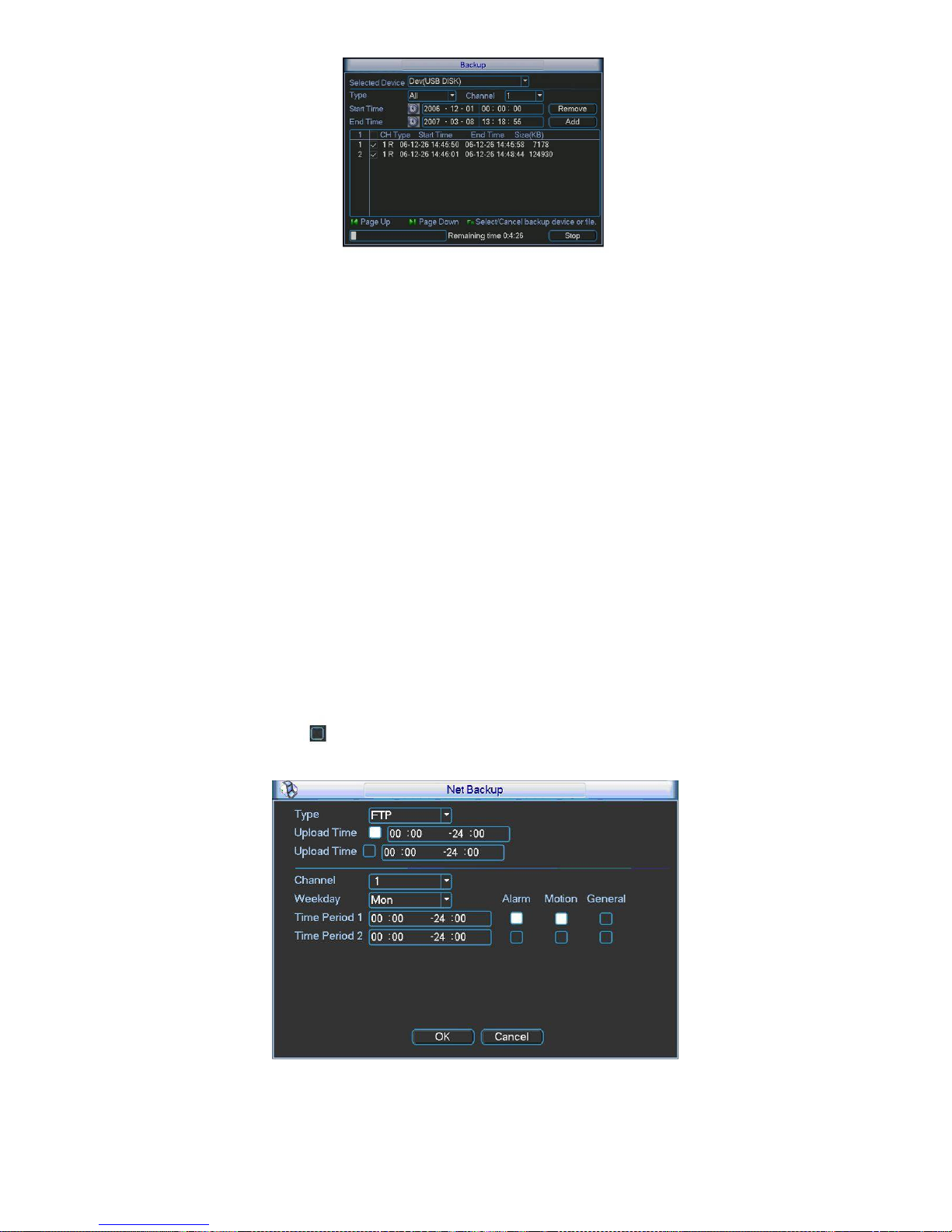
63
Figure 5-47
Tips:
During backup process, you can click ESC to exit current interface for other operation. The
system will not terminate backup process.
Note:
When you click stop button during the burning process, the stop function becomes activated
immediately. For example, if there are ten files, when you click stop system just backup five
files, system only save the previous 5 files in the device (But you can view ten file names).
5.8.3 Network Backup
The network backup interface is shown as in 303HFigure 5-48. Pease set network backup type
and upload time. Right now, the network backup supports FTP only. You can go to chapter
5.6.4.7 Network storage (Main menu->Setting->Network-> Network storage) to set storage
path.
There are two upload periods. You can highlight the corresponding icon to select the upload
time.
Then you can set the record period and highlight the corresponding icon to select the record
time.
Please highlight icon
to select the corresponding function. After setting all the setups
please click OK button, system goes back to the previous menu.
Figure 5-48
Important
Page 64

64
Upload time is network backup time while Time period is system record time.
5.9 Shutdown
Double click shutdown button, system pops up a dialogue box for you to select. See 304HFigure 5-49.
z Logout menu user: log out menu. You need to input password when you login the next time.
z Restart application: reboot device.
z Shutdown: system shuts down and turns off power.
z Restart system: system begins rebooting.
z Switch user: you can use another account to login.
If you shut down the device, there is a process bar for your reference, system waits for 3
seconds and then shut down (You can not cancel).
Please note, sometimes you need to input the proper password to shut down the device.
Figure 5-49
Page 65

65
6 Quick Configuration Tool
6.1 Overview
Quick configuration tool can search current IP address, modify IP address. At the same time, you
can use it to upgrade the device.
Please note the tool only applies to the IP addresses in the same segment.
6.2 Operation
Double click the “ConfigTools.exe”icon, you can see an interface is shown as in 305HFigure 6-1.
In the device list interface, you can view device IP address, port number, subnet mask, default
gateway, MAC address and etc.
Figure 6-1
Select one IP address and then right click mouse, you can see an interface is shown as in
306HFigure
6-2.
Page 66

66
Figure 6-2
Select the “Open Device Web” item; you can go to the corresponding web login interface. See
307HFigure 6-3.
Figure 6-3
If you want to modify the device IP address without logging in the device web interface, you can
go to the configuration tool main interface to set.
In the configuration tool search interface (
308HFigure 6-1), please select a device IP address and then
double click it to open the login interface. Or you can select an IP address and then click the
Login button to go to the login interface. See
309HFigure 6-4.
In
310HFigure 6-4, you can view device IP address, user name, password and port. Please modify the
corresponding information to login.
Please note the port information here shall be identical with the port value you set in TCP port in
Web Network interface. Otherwise, you can not login the device.
If you are use device background upgrade port 3800 to login, other setups are all invalid.
Figure 6-4
After you logged in, the configuration tool main interface is shown as below. See
311HFigure 6-5.
Please refer to the Quick Configuration Tool User's Manual included in the resources CD for
detail information.
Page 67

67
Figure 6-5
Page 68

68
7 Web
7.1 General Introduction
The device web provides channel monitor menu tree, search, alarm setup, system setup, PTZ
control and monitor window.
Important
The following operation is based on 16-channel series device.
7.1.1 Preparation
Before log in, please make sure:
z PC and NVR connection is OK.
z You have set PC IP address, NVR IP address, subnet mask and gateway. (Please set the IP
address of the same section for the PC and NVR. Please input corresponding gateway and
subnet mask if there are routers.)
z Use order ping ***.***.***.***(NVR IP address) to check connection is OK or not. Usually the
return TTL value should be less than 255.
7.1.2 Log in
Open the IE and then input the NVR IP address in the address column.
For example, if your NVR IP address is 192.168.1.108, then please input http:// 192.168.1.108 in
IE address column. See Figure 7-1.
Figure 7-1 IE Interface
System pops up warning information to ask you whether install webrec.cab control or not. Please
click yes button.
If you can’t download the ActiveX file, please modify your settings as follows. See Figure 7-2.
Input IP
address here.
Page 69

69
Figure 7-2 IE Safety Setup
After installation, the interface is shown as below. See Figure 7-3.
Figure 7-3 Login interface
Please input your user name and password.
Default factory name is admin and password is admin.
Note: For security reasons, please modify your password after you first login.
7.2 Main Interface
NVR web main interface is shown as in Figure 7-4.
Page 70

70
Figure 7-4 Web Main Interface
There are six sections:
z Section 1: Monitor channel menu tree
z Section 2: System menu
z Section 3: PTZ control
z Section 4: Video setup and other setup
z Section 5: Preview window
z Section 6: Monitor window switch
7.2.1 Monitor Channel Menu Tree
The monitor channel menu tree is shown as in Figure 7-5.
Figure 7-5 Monitor Channel Menu Tree
Please refer to the following sheet for detailed information.
①
②
③
④
⑥
⑤
Page 71

71
Parameter Function
CAM 1 to CAM
16
channel 1 to channel 16
Open all /close
all
Click this button to open all video channels.
Once all video channels are open, it becomes close all button.
Start dialogue
You can click this button and then select the corresponding
audio compression mode (default/G.711a) to enable/disable
bidirectional talk function.
Local play Click local play button to select file to play in PC.
Refresh Click this button to refresh monitor channel name.
Please left click one monitor to view real-time video, the monitor window is shown as in
312HFigure
7-6.
Figure 7-6 Real-time Monitor
Please refer to the following sheet for monitor window parameter information.
SN Parameter Function
1-4 Display
device
information
z 1: NVR IP address.
z 2: Channel number.
z 3: Bit stream.
z 4: Bit stream decode type.
¾ S1: Overlay.
¾ S2: Off stream.
¾ S3:GD1
¾ H1: Overlay
¾ H2: off stream decoding from the display card.
1 2 3 4 5 6 7 8 910
11
Page 72

72
5 Digital
zoom
Click this button and then left drag the mouse in the zone to
zoom in. Right click mouse system restores original status.
6 Change
show
mode
Resize or switch to full screen mode.
7 Local
record
When you click local record button, the system begins
recording. The recorded file is saved to system folder: \
RecordDownload(default).
8 Capture
picture
You can snapshoot important video. All images are memorized
in system folder: \ picture download (default).
9 Audio
Turn on or off audio.(It has no relationship with system audio
setup )
10 Close
video
Close video in current window.
11 Channel
number
Current view channel number.
7.2.2 System Menu
System menu is shown as in .Figure 7-7.
Please refer to chapter 7.3 Configuration, chapter 7.4 Search, chapter 7.5 Alarm, chapter 7.6
About, chapter 7.7 Log out for detailed information.
Figure 7-7 System Menu
7.2.3 Monitor Window Switch
The monitor window switch interface is shown as in Figure 7-8.
Figure 7-8 Monitor Window Switch
System supports 1/4/6/8/9/13/16/20/25/36-window real-time preview.
----It is video quality adjustment button. It has relationship with decode via software.
--Fluency button. You can use this function to adjust the priority between real-time and
fluency.
7.2.4 Preview Window Switch
The preview window switch interface is shown as in Figure 7-9.
NVR series products do not support this function.
Figure 7-9 Preview Window Switch
7.2.5 PTZ Control
Before PTZ operation, please make sure you have properly set PTZ protocol. (Please refer to
chapter 7.3.2.6 PTZ).
Page 73

73
Here you can view direction keys, speed, zoom, focus, iris, preset, tour, pan, scan, pattern, aux
close, and PTZ setup button.
Please note: open menu/close menu/up/down/left/right/confirm/cancel buttons are for speed
dome only.
z PTZ direction: PTZ supports eight directions: left/right/up/down/upper left/upper right/bottom
left/bottom right.
z Speed: The step 8 speed is faster than step 1.
Figure 7-10 PTZ Interface
Click PTZ set button, the interface is shown as in Figure 7-11.
You can click this icon to
display or hide the PTZ
control platform.
These six buttons are for
speed dome only.
Page 74

74
Figure 7-11 PTZ Setup
Please refer to the following sheet for PTZ setup information.
Parameter Function
Scan
z Move the camera to you desired location and then click left limit
button.
z Then move the camera again and then click right limit button to
set a right limit.
Preset
Use direction keys to move the camera to your desired location and
then input preset value. Click add button, you have set one preset.
Tour
z Input auto tour value and preset value. Click add button, you
have added one preset in the tour.
z Repeat the above procedures you can add more presets in one
tour.
z Or you can click delete button to remove one preset from the
tour.
Pattern
You can input pattern value and then click start record button to
begin PTZ movement. Please go back to Figure 7-10 to implement
camera operation. Then you can click stop record button in Figure 7-
11. Now you have set one pattern.
Assistant
The assistant items include: BLC, Digital zoom, night vision, camera
brightness, flip.
You can select one option and then click start or stop button.
Matrix Please select matrix x and then input corresponding monitor output
channel number, video input channel number. Then you can click
video switch button.
Light/wiper You can control the light and wiper of the peripheral device. Please
note the peripheral device shall support this function.
Page 75

75
7.2.6 Color and More Setup
Color and other setup interface are shown as in 313HFigure 7-12.
Figure 7-12 Color
Please refer to the following sheet for detailed information.
Parameter Function
It is to adjust monitor video
brightness.
It is to adjust monitor video contrast
ness.
It is to adjust monitor video
saturation.
It is to adjust monitor video hue.
Video
setup
Reset Restore system default value.
Note:
All the operation here
applies to WEB end only.
Click more button, the interface is shown as in
314HFigure 7-13.
Figure 7-13 Color and More
Please refer to the following sheet for detailed information.
Parameter Function
Picture
Path
Click picture path button, system pops up an interface for you
to modify path.
Record
Path
Click record path button, system pops up an interface for you
to modify path.
More
Reboot Click this button to reboot device.
7.3 Configuration
7.3.1 System Information
Page 76

76
7.3.1.1 Version Information
Here you can view device hardware feature and software version information. See 315HFigure 7-14.
Figure 7-14 Version Information
7.3.1.2 HDD information
Here you can view local storage status such as free capacity and total capacity. See 316HFigure 7-15.
Figure 7-15 HDD Information
7.3.1.3 Log
Here you can view system log. See 317HFigure 7-16.
Page 77

77
Figure 7-16 Log
Click backup button, the interface is shown as in
318HFigure 7-17.
Figure 7-17 Save Log
Please refer to the following sheet for log parameter information.
Parameter Function
Type
Log types include: system operation, configuration operation, data
management, alarm event, record operation, user management, log
clear and file operation.
Search
You can select log type from the drop down list and then click search
button to view the list.
Clear You can click this button to delete all displayed log files. Please note
system does not support clear by type.
Backup
You can click this button to backup log files to current PC.
7.3.2 System Configuration
Please click save button to save your current setup. Please click refresh button to view
the latest setup.
7.3.2.1 General Setup
Page 78

78
Here you can set system time, record length, video format and etc. See
319HFigure 7-18.
Figure 7-18 General Setup
Figure 7-19 DST
Figure 7-20 DST
Please refer to the following sheet for detailed information.
Parameter Function
System
Time
Here is for you to modify system time. Please click Save button after
your completed modification
Sync PC You can click this button to save the system time as your PC current
time.
Page 79

79
Data
Format
Here you can select data format from the dropdown list.
Data
Separator
Please select separator such as – or /.
Time
Format
There are two options: 24-H and 12-H.
DST Here you can set day night save time begin time and end time. See
Figure 7-19 and Figure 7-20.
Language Here you can view the system current language. You can select
from the dropdown list.
HDD Full
There are two options: stop recording or overwrite the previous files
when HDD is full.
Pack
Duration
Here you can select file size. The value ranges from 1 to 120
(minute). Default setup is 60 minutes.
Device No
When you are using one remote control to manage multiple devices,
you can give a serial numbers to the device.
Please note current series product does not support this function.
Video
Standard
Here you can view video format such as PAL.
7.3.2.2 Schedule
Here you can set different periods for various days. There are max six periods in one day. See
320HFigure 7-21.
Figure 7-21 Schedule
Page 80

80
Figure 7-22 Schedule Time
Figure 7-23 Copy
Please refer to the following sheet for detailed information.
Parameter Function
Channel
Please select a channel first.
Pre-record Please input pre-record value here.
When alarm record or motion detection record occurs, system can
record the several seconds video before activating the record
operation into the file. (Depends on data size).
Setup
z
In 321HFigure 7-21, click set button, you can go to the corresponding
setup interface.
z
Please set schedule period and then select corresponding record
type: schedule, motion detection, and alarm.
z
Please select date (Current setup applies to current day by default.
You can draw a circle before the week to apply the setup to the
whole week.)
z
After complete setup, please go back to 322HFigure 7-21 and then click
save to save current time period setup.
Page 81

81
Parameter Function
Copy It is a shortcut menu button. You can copy current channel setup to
one or more (all) channels. The interface is shown as in Figure 7-
23.
Save You can click save button after you complete setup for one channel,
or you can complete the whole setups and then click save button.
Refresh Click this button to get device latest configuration information.
7.3.2.3 RS232
The RS232 interface is shown as in 323HFigure 7-24.
Figure 7-24 RS232
Please refer to the following sheet for detailed information.
Parameter Function
RS232 There is only one option COM 01, corresponding to RS232.
Console is for debug.
Control keyboard: Switch between RS232 and control
keyboard.
Network keyboard: COM control protocol. You can use
network keyboard to control NVR via COM.
Transparent COM: Network user can communicate with
RS232 COM device.
Function
PTZ matrix: PTZ matrix protocol. You can use the device to
control the PTZ matrix.
Data Bit
The value ranges from 5 to 8.
Page 82

82
Parameter Function
Stop Bit
There are three options: 1/2.
Baud Bit You can select corresponding baud bit here.
Parity
There are five options: none/odd /even/mark/space.
7.3.2.4 Network
Network interface is shown as in 324HFigure 7-25.
Figure 7-25 Network
Please refer to the following sheet for detailed information.
Parameter Function
Ethernet Please select the network card first.
DHCP Dynamically get IP address. You can get the device IP from
the DHCP server if you enabled this function.
TCP Port Default value is 37777.
HTTP Port Default value is 80.
UDP Port Default value is 37778.
Max Connection Network user max amount. The value ranges from 1 to 10.
Network
transmission QoS
You can set the priority between fluency and video quality.
System can automatically adjust the bit stream according to
the network bandwidth.
Page 83

83
Parameter Function
High-Speed
Download
Download the recorded file maximally using the network
bandwidth.
Multiple
cast
group
z
Set MULCAST address and port.
z
Enable MULCAST function.
Remote
Host
PPPOE
z
Input the PPPoE user name and password you get from the
IPS (internet service provider) and enable PPPoE function.
Please save current setup and then reboot the device to
get the setup activated.
z
Device connects to the internet via PPPoE after reboot.
You can get the IP address in the WAN from the IP address
column.
Note
If you want to reboot the device, please make sure
z The Web logged in account has the right to reboot the
device.
z There is no logged in user at the local end.
Email
The email interface is shown as in
325HFigure 7-26.
Figure 7-26 Email
Please refer to the following sheet for detailed information.
Parameter Function
SMTP Server
Input server address and then enable this function.
You can also input the corresponding server domain name
here, but you need to go to DNS interface (chapter 7.3.4.1) to
set the server IP that can parse the domain.
Page 84

84
Parameter Function
SSL enable
You can enable SSL encryption function to guarantee data
safety.
Port Default value is 25. You can modify it if necessary.
User Name
The sender email account user name.
Password
The sender email account password.
Sender
Sender email address.
Subject
Input email subject here. Max 32-digit.
Address
Input receiver email address here. Max input three addresses.
Interval
Please input the send interval value here.
DDNS
The DDNS interface is shown as in
326HFigure 7-27.
Figure 7-27 DDNS
Please refer to the following sheet for detailed information.
Parameter Function
Server Type You can select DDNS protocol from the dropdown list and then
enable DDNS function. The private DDNS protocol means you
use our self-defined private protocol to realize DDNS function.
Server IP DDNS server IP address
Server Port DDNS server port.
Domain Name Your self-defined domain name.
User The user name you input to log in the server.
Page 85

85
Parameter Function
Password The password you input to log in the server.
Interval
z
Device sends out alive signal to the server regularly.
z
You can set interval value between the device and DDNS
server here.
NAS
NAS interface is shown as in
327HFigure 7-28.
Figure 7-28 NAS
Figure 7-29 NAS Setup
Please refer to the following sheet for detailed information.
Page 86

86
Parameter Function
NAS enable
Please select network storage protocol and then enable
NAS function. The network storage protocol includes
FTP.
Server IP Input remote storage server IP address.
Port
Input Remote storage server port number.
User Name
Log in user account.
File length The max files length when you transfer the file. When
the input value is 0, then system upload the whole files.
Password The password you need to login the server.
Remote Path Remote storage file path.
Setup
z
In NAS interface, click set button, you can go to the
corresponding setup interface. See Figure 7-29.
z
Please set schedule period and then select
corresponding record type: schedule/alarm. Please
note device does not support motion detect record
function now.
z
Please select date (Current setup applies to current
day by default. You can draw a circle before the week
to apply the setup to the whole week.)
z
After complete setup, please go back to Figure 7-28
and then click save to save current time period setup.
Save You can click save button after you complete setup for
one channel, or you can complete the whole setups and
then click save button.
Refresh Click this button to get device latest configuration
information.
NTP
The NTP interface is shown as in
328HFigure 7-30.
Here you can realize network time synchronization. Please enable current function and then
input server IP, port number, time zone and time.
Page 87

87
Figure 7-30 NTP
Please refer to the following sheet for detailed information.
Parameter Function
Enable Enable NTP function or not.
Server IP Server IP address
Port Server port. System supports TCP only and default port
value is 123.
Time Zone Device current time zone.
Update Interval Time update interval value.
Alarm Centre
Alarm centre interface is shown as below.
Please input alarm centre server IP, port number. Once there is an alarm occurred, system can
notify the alarm centre as you specified here.
Page 88

88
Figure 7-31
7.3.2.5 Alarm
Alarm setup interface is shown as in 329HFigure 7-32.
Figure 7-32 Alarm Setup
Page 89

89
Figure 7-33 PTZ Setup
Please refer to the following sheet for detailed information.
Parameter Function
Event
Type
It includes local alarm/network alarm/other.
z
Local alarm: Device detects alarm from input port.
z
Network: Device detects alarm from network.
Alarm in Select corresponding alarm channel.
Enable You need to draw a circle here so that system can detect the alarm
signal.
Type
There are two options: normal open and normal close. NO becomes
activated in low voltage, NC becomes activated in high voltage.
Period
z
Alarm record function becomes activated in the specified periods.
z
There are six periods in one day. Please draw a circle to enable
corresponding period.
z
Select date. If you do not select, current setup applies to today only.
You can select all week column to apply to the whole week.
z
Click OK button, system goes back to alarm setup interface, please
click save button to exit.
Anti-dither
System only memorizes one event during the anti-dither period. The
value ranges from 0 to 15s.
Normal
Out
Enable alarm activation function. You need to select alarm output port
so that system can activate corresponding alarm device when alarm
occurs.
For 6-ch alarm output port device, the 6
th
channel is the controllable
+12V output.
Alarm
Latch
System can delay the alarm output for specified time after ala
ended. The value ranges from 10 seconds to 300 seconds.
Record
Channel
System auto activates current channel to record once alarm occurs
(working with alarm activation function). Please note current device
shall be in auto record mode (Chapter 7. 3.2.2 Schedule).
Record
Latch
System can delay the record for specified time after alarm ended.
T
value ranges from 10s to 300s.
Email
Please draw a circle to enable email function. System can send
o
email to alert you when alarm occurs and ends.
Page 90

90
Parameter Function
Tour Display the selected video in local monitor window. When alarm
occurs, system can begin one-window tour for the activated record
channel. Please set the tour time in the local end.
PTZ
activation
z
Here you can set PTZ movement when alarm occurs. Such as go to
preset x when there is an alarm.
z
The PTZ configuration events include preset, tour, and pattern.
Copy It is a shortcut menu button. You can copy current channel setup to
one or more (all) channels.
Save You can click save button after you complete setup for one channel,
or you can complete the whole setups and then click save button.
Refresh Click this button to get device latest configuration information.
7.3.2.6 PTZ
PTZ interface is shown as in 330HFigure 7-34
Please note, before operation please make sure you have set speed dome address and the NVR
and speed dome connection is OK.
Figure 7-34 PTZ
Please refer to the following sheet for detailed information.
Parameter Function
Channel
You can select monitor channel from the dropdown list. .
Protocol
Select the corresponding dome protocol.(such as PELCOD)
Address
Set corresponding dome address. Default value is 1. Please note your
setup here shall comply with your dome address; otherwise you can
not control the speed dome.
Baud
Rate
Select the dome baud rate. Default setup is 9600.
Page 91

91
Parameter Function
Data Bit Default setup is 8. Please set according to the speed dome dial switch
setup.
Stop bit
Default setup is 1. Please set according to the speed dome dial switch
setup.
Parity Default setup is none. Please set according to the speed dome dial
switch setup.
Save You can click save button after you complete setup for one channel,
or you can complete the whole setups and then click save button.
Refresh Click this button to get device latest configuration information.
7.3.2.7 Default & Backup
Default: Restore factory default setup. You can select corresponding items.
Backup: Export current configuration to local PC or import configuration from current PC.
Please refer to
331HFigure 7-35.
Please note system can not restore some information such as network IP address.
Figure 7-35 Default and Backup
Please refer to the following sheet for detailed information.
Parameter Function
Select All Restore factory default setup.
Export
Configuration
Export system configuration to local PC.
Import
Configuration
Import configuration from PC to the system.
7.3.3 Advanced
Page 92

92
7.3.3.1 HDD Management
Please select the storage device first and then you can see the items on your right become valid.
You can check the corresponding item here. See
332HFigure 7-36.
Figure 7-36 HDD Management
Please refer to the following sheet for detailed information.
Parameter Function
Format Clear data in the HDD.
Read/write Set current HDD as read/write
Read only Set current HDD as read.
Redundant Set current HDD as redundant HHD.
Recover Fix the HDD error. Right now the device does not support this
function.
7.3.3.2 Alarm I/O
Here you can search alarm output status. See 333HFigure 7-37.
Page 93

93
Figure 7-37 Alarm I/O Configuration
Important
The alarm output port should not be connected to high power load directly (It shall be less than
1A) to avoid high current which may result in relay damage. Please use the co contactor to
realize the connection between the alarm output port and the load.
Please refer to the following sheet for detailed information.
Parameter Function
Alarm output For A series product, there are three channels.
For L and S series product, there are six channels. The 6
th
channel is the controllable +12V alarm output.
Please click the corresponding number and then click the trigger
button.
Trigger Enable/disable alarm output.
Please note once you activate an alarm manually, you need to
click the output channel number again and then click trigger
button to disable it. Otherwise the alarm can not be cancelled.
Refresh
Search alarm output status.
7.3.3.3 Record
Record control interface is shown as in 334HFigure 7-38.
Page 94

94
Figure 7-38 Record
Please refer to the following sheet for detailed information.
Parameter Function
Schedule
System enables auto record function as you set in schedule setup
(chapter 7.3.2.2).
Manual
Enable corresponding channel to record no matter what period
applied in the record setup.
Stop
Stop current channel record no matter what period applied in the
record setup.
7.3.3.4 Account
Here you can add, remove user or modify password. See 335HFigure 7-39.
Page 95

95
Figure 7-39 Account
7.3.3.5 Auto Maintenance
Here you can select auto reboot and auto delete old files interval from the dropdown list. See
336HFigure 7-40.
Figure 7-40 Auto Maintenance
7.3.3.6 Abnormity
The abnormity interface is shown as below.
Page 96

96
Figure 7-41 Abnormity
Please refer to the following sheet for detailed information.
Parameter Function
Event
Type
z
The abnormal events include: no disk, no space, disk error, offline, IP
conflict.
z
You need to draw a circle to enable this function.
z
Threshold: It refers to the HDD free space.
Normal
Out
The corresponding alarm output channel when alarm occurs.
For A series product, there are three channels.
For L and S series product, there are six channels. The 6
th
channel is
the controllable +12V alarm output.
Latch The alarm output can delay for the specified time after alarm stops. The
value ranges from 10s to 300s.
Record
channel
After you selected the disk connection option, once the device is offline,
the activated channel can begin alarm record.
Record
latch
System can delay the record for specified time after alarm ended. The
value ranges from 10s to 300s.
Send
email
If you enable this function, system can send out email to alarm the
specified user.
Show
message
Once you check the box to enable this function, system can display the
alarm icon on the right of the channel name at the local end.
7.3.4 Additional Function
7.3.4.1 DNS
Here you can set server or local operator DNS address. See Figure 3-34.
Once you input the domain name in SMTP server in the email interface (chapter 7.3.2.4 Network-
>email), you need to input the corresponding address here, otherwise the device can not parse
Page 97

97
the domain name.
Figure 7-42 DNS
7.3.4.2 Remote Device
Click remote device item, the interface is shown as below.
Figure 7-43 Remote Device
Please refer to the following sheet for detailed information.
Page 98

98
Parameter Function
Channel Please select the local device channel number to connect to the remote device..
You need to highlight the enable item to activate this function. Now you can see
remote device type, IP address and etc.
Manufacturer The IPC or NVS manufacturer.
Device type You can select the remote device type from the dropdown list.
Model There are two models: standard definition device and high definition device.
When you select a high definition device, it is equal to connect to 4-ch standard
definition devices.
For example, the 16-channel series product can connect to 4 high definition
devices. If you have connected to one high definition device, you can still connect
12-channel standard devices. There are 13 monitor windows.
IP address,
port, remote
channel.
Please input remote device IP address, port number, remote device channel
number and account.
User, password Please input account to login the remote device.
IP search Please click the search IP button to search the all remote devices available.
Please note system can only search the devices in the same segment and the
device shall disable the firewall.
Remote device
information
Here you can view remote device name, Mac address, IP address and TCP port.
7.4 Search
Click search button, you can see an interface is shown as in 337HFigure 7-44.
Please select record playback mode, and then select start time, end time and channel. Then
please click search button, you can see the corresponding files in the list.
Select the file(s) you want to download and then click download button, system pops up a
dialogue box shown as in
338HFigure 7-45 , and then you can specify file name and path to download
the file(s) to your local pc. Click OK to complete the download procedure.
Click play button, system plays the recorded file in the corresponding monitor channel. You can
select several channels to play in multiple-channel.
Page 99

99
Figure 7-44 Search Main Interface
Figure 7-45 Save as
Please refer to the following sheet for detailed information.
Type Parameter Function
Record Search general record, alarm record and motion
detection record.
Alarm Search alarm record.
Motion
Detection
Search motion detection record.
This function is not available in current device.
Local Search local record.
Snapshot Search snapshot file. This function is not available in
current device.
Type
Card This function is not available in current device.
Item Start time Set the file start time.
Page 100

100
Type Parameter Function
End time Set the file end time.
Channel Select the channel from the dropdown list.
Search Click this button you can view the recorded file matched
your requirements.
Playback Select the file first and then click playback button to view
the video.
Download
type
Download by file: Select the file(s) and then click
download button.
Download by time: Download the recorded file(s) within
your specified period.
Download Select the file you need (multiple choices) and then click
download button, you can see system pops up a
dialogue box. See
339HFigure 7-45.
Input the downloaded file name, specify the path and
then click OK button. You can see system begins
download and the download becomes stop button. There
is a progress bar for your reference.
Operation
Open local
record
Select local record to play.
Multiplechannel
playback
System supports playback one file in several monitor
channels.
During the playback process, you can see there are control buttons such as play, pause, stop.
slow play and fast play in the play process bar. You can view current playback file channel name,
time and data statistics.
7.5 Alarm
Click alarm function, you can see an interface is shown as in 340HFigure 7-46.
Here you can set device alarm type and alarm sound setup.
When alarm occurs, system can display the alarm information in the corresponding interface.
For motion detect, video loss, camera masking, you need to set the event in the motion detection
interface. Current series product does not support this function.
 Loading...