

Page 1

Mobile DVR User’s Manual
1
Page 2

Table of Contents
1 FEATURES AND SPECIFICATIONS.................................................................. 8
2 OVERVIEW AND CONTROLS .........................................................................10
2.1 Front Panel ...........................................................................................................................................10
2.2 Remote Control....................................................................................................................................10
2.3 Mouse Control......................................................................................................................................11
3 INSTALLATION AND CONNECTIONS............................................................. 14
3.1 Check Unpacked DVR........................................................................................................................14
3.2 Device installation................................................................................................................................14
4 OVERVIEW OF NAVIGATION AND CONTROLS ............................................ 15
4.1 Login, Logout & Main Menu ...............................................................................................................15
4.1.1 Login ................................................................................................................................................. 15
4.1.2 Main Menu ....................................................................................................................................... 15
4.1.3 Logout............................................................................................................................................... 16
4.1.4 Auto Resume after Power Failure ................................................................................................ 16
4.2 Recording Operation...........................................................................................................................16
4.2.1 Live Viewing..................................................................................................................................... 16
4.2.2 Manual record.................................................................................................................................. 17
4.3 Search & Playback ..............................................................................................................................19
4.3.1 Search Menu ................................................................................................................................... 19
4.3.2 Basic Operation............................................................................................................................... 20
2
Page 3

4.4 Record Setup (Schedule) ...................................................................................................................21
4.4.1 Schedule Menu .................................................................................................................................... 21
4.4.2 Basic Operation.................................................................................................................................... 21
4.5 Detect ....................................................................................................................................................23
4.5.1 Go to Detect Menu............................................................................................................................... 23
4.5.2 Detect..................................................................................................................................................... 23
4.5.3 Video Loss.............................................................................................................................................25
4.5.4 Camera Mask Detect........................................................................................................................... 26
4.6 Alarm Setup and Alarm Activation ....................................................................................................27
4.6.1 Go to alarm setup interface ...........................................................................................................27
4.6.2 Alarm setup...................................................................................................................................... 27
4.7 Backup ..................................................................................................................................................29
4.7.1 Detect Device....................................................................................................................................... 29
4.7.1 Backup (Including one-button backup)........................................................................................30
4.8 PTZ Control and Color Setup ............................................................................................................32
4.8.1 Cable Connection ................................................................................................................................ 32
4.8.2 PTZ Setup.............................................................................................................................................32
4.8.3 3D Intelligent Positioning Key............................................................................................................ 34
4.9 Preset/ Patrol/Pattern/Scan................................................................................................................34
4.9.1Preset Setup .........................................................................................................................................35
4.9.2 Activate Preset..................................................................................................................................... 35
4.9.3 Patrol setup (Tour Setup)................................................................................................................... 35
4.9.4 Activate Patrol (tour) ........................................................................................................................... 36
4.9.5 Pattern Setup.......................................................................................................................................36
4.9.6 Activate Pattern Function...................................................................................................................36
4.9.7 Auto Scan Setup .................................................................................................................................36
4.9.8 Activate Auto Scan.............................................................................................................................. 37
4.10 Flip .........................................................................................................................................................37
5 UNDERSTANDING OF MENU OPERATIONS AND CONTROLS ................... 38
5.1 Menu Tree ............................................................................................................................................38
3
Page 4

5.2 Main Menu ............................................................................................................................................38
5.3 Setting ...................................................................................................................................................39
5.3.1 General............................................................................................................................................. 39
5.3.2 Encode .............................................................................................................................................41
5.3.3 Schedule .......................................................................................................................................... 42
5.3.4 RS232............................................................................................................................................... 42
5.3.5 Network ............................................................................................................................................ 43
5.3.6 Alarm................................................................................................................................................. 50
5.3.7 Detect ...............................................................................................................................................50
5.3.8 Pan/Tilt/Zoom .................................................................................................................................. 50
5.3.9 Display..............................................................................................................................................51
5.3.10 Default.......................................................................................................................................... 52
5.4 Search ...................................................................................................................................................53
5.5 Advanced ..............................................................................................................................................53
5.5.1 HDD Management..........................................................................................................................54
5.5.2 Alarm Output....................................................................................................................................55
5.5.3 Abnormity .........................................................................................................................................55
5.5.4 Manual Record................................................................................................................................56
5.5.5 Account.............................................................................................................................................56
5.5.6 Auto Maintain................................................................................................................................... 57
5.5.7 TV Adjust.......................................................................................................................................... 57
5.6 Information............................................................................................................................................58
5.6.1 HDD Information ............................................................................................................................. 58
5.6.2 BPS...................................................................................................................................................59
5.6.3 Log .................................................................................................................................................... 59
5.6.4 Version .............................................................................................................................................60
5.6.5 Online Users....................................................................................................................................60
5.7 Exit .........................................................................................................................................................60
6 WEB CLIENT OPERATION .............................................................................. 62
6.1 Network Connection............................................................................................................................62
6.2 Login......................................................................................................................................................62
4
Page 5

6.2.1 Real-time Monitor............................................................................................................................ 65
6.2.2 PTZ ...................................................................................................................................................66
6.2.3 Color .................................................................................................................................................69
6.2.4 Picture Path and Record Path ......................................................................................................69
6.2.5 Menu Interface Switch.................................................................................................................... 70
6.3 Configure .............................................................................................................................................. 71
6.3.1 System Information......................................................................................................................... 71
6.3.2 Setting............................................................................................................................................... 73
6.4 Search ...................................................................................................................................................93
6.4.1 Download ......................................................................................................................................... 94
6.5 Alarm .....................................................................................................................................................95
6.6 About .....................................................................................................................................................95
6.7 Log out ..................................................................................................................................................96
6.8 Un-install Web Control........................................................................................................................ 96
APPENDIX A HDD CAPACITY CALCULATION ...................................................... 97
APPENDIX B COMPATIBLE USB DRIVE LIST ....................................................98
APPENDIX C COMPATIBLE CD/DVD BURNER LIST.......................................... 99
5
Page 6

Welcome
Thank you for purchasing our DVR!
This operating manual is designed to be a reference tool for the installation and
operation of your system.
Here you can find information about this series DVR features and functions, as well
as a detailed menu tree.
Before installation and operation please read the following safeguards and warnings
carefully!
6
Page 7

Important Safeguards and Warnings
1.Electrical safety
All installation and operation here should conform to local electrical safety codes.
We assume no liability or responsibility for all the fires or electrical shock caused by
improper handling or installation.
2.Transportation security
Heavy stress, violent vibration or water splash are not allowed during transportation,
storage and installation.
3.Installation
Keep upwards. Handle with care.
Do not apply power to the DVR before completing installation.
Do not place objects on the DVR
4.Qualified engineers needed
All the examination and repair work should be done by the qualified service
engineers.
We are not liable for any problems caused by unauthorized modifications or
attempted repair.
5.Environment
The DVR should be installed in a cool, dry place away from direct sunlight,
inflammable, explosive substances and etc.
6. Accessories
Be sure to use all the accessories recommended by manufacturer.
Before installation, please open the package and check all the components are
included:
7
Page 8

1 FEATURES AND SPECIFICATIONS
Specification
System
Record
OS LINUX
Operation Interface Graphic user interface
Operation Method 1.Remote control 2.Mouse
3.Network keyboard 4.Network
External Interface
Storage Device 2.5 inches HDD as the main storage device
Record Mode
Playback
Mode
Video Input Format/Standard
Video
Input Port
Parameter
Video
Output
Port
Parameter
Real-time Monitor Video
Resolution
Real-time Monitor Plane
Definition
Record Compression
Method
Video Record Speed
Record
Resolution
Record Video Quality 1-6 level (Adjustable)
Playback Plane Resolution 240 TV Line
Record Video Information
Search(support
search
engineers)
Playback
Control
Video 4-Ch real-time record Record
Audio 4-ch audio input
Port BNC
Input
Resistance
Input Signal 1.0Vp-p
Port BNC
Output
Resistance
Output Signal 1.0Vp-p
CIF
1.Power input port
2.Audio/Video input port
3.Video output port
4.Audio output port
5.High-speed USB2.0 port
6.RS232 port
7.RJ45 network port
1.Automatically begin record once boots up
2. Schedule auto record. Delayed turn off.
3.Activation record once alarm occurs
1.Time
2.Alarm
3.Channel
1.Freely switch video playback file
2. Integrate multiple playback speeds such as
normal playback, slow speeds or fast speeds.
PAL(625 Line,50f/s)/NTSC(525 Line,
60f/s)
75Ω
75Ω
704×576(PAL)/720×480(NTSC)
440 TV Line
H.264
PAL: 1-25f/s(Adjustable)
NTSC:1-30f/s(Adjustable)
PAL: 352×288
NTSC:360×240
Time information
Channel information
Vehicle information
8
Page 9

Plate number
Temperature
Record Backup Method High-speed USB2.0 mobile device support local
backup.
Record Video Bit stream
Record file Way Create a file at 10M/15M/20M/30M/60M
Audio
Input Port
Parameter
Audio
Output
Port
Parameter
Audio Output Signal to Noise
Ratio
Sampling
Audio Encode Method PCM
Audio Bit Stream 56.25MB/H
Port BNC
Input
Resistance
Input Signal
Port BNC
Output
Resistance
Output Signal
Sampling
Frequency
Sampling Bit 16-bit
1-ch CIF:40~460MB/H(Depends on the video
content)
20KΩ
200~2800mV
1KΩ
200~2800mV
≥75dB
8KHz Audio
Auxiliary
Function
Others
Scheduled boot up Support scheduled boot up function to make sure
there are recorded video in the specified period,
Vibration
Rated Power
Rated Current
Start Current ≤1.5A
Average Power
Temperature
Humidity
Atmosphere Pressure
Net Weight
Unit Dimension 179(W)×54(H)×185(D) mm
Installation Rack Installation
≥8 H@ frequency 0~100Hz,Extent:10MM
+12V / +24V / +42V(+8V~+60V)
≤1A(Including HDD)
10W(Including HDD)
0℃~+60℃(Ordinary HDD)
10%~95%
86Kpa~106Kpa
1.7Kg(Including HDD)
Features and specification are subject to change without prior notice.
9
Page 10
2 OVERVIEW AND CONTROLS
This section provides information about front panel and rear panel. If you install this
series DVR for the first time, please refer to this part first.
2.1 Front Panel
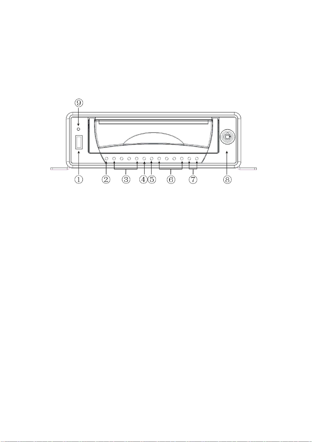
This series DVR front panel is shown as in Figure 2-1 .
Figure 2-1
① USB 2.0 data port
② Power indication light: It becomes on when connect device to the power.
③ 1-4ch record status indication light: It becomes on when record. It flashes
when there is abnormal situation.
④ backup indication light: It flashes when system backups. It becomes on when
backup completes.
⑤ Upgrade indication light.
⑥ 1-4ch alarm input light. It becomes on when there is input alarm.
⑦ .2-ch alarm output indication light. It becomes on when there is output alarm.
⑧ Door key
⑨ IR remote control receiver.
2.2 Remote Control
The remote control interface is shown as in Figure 2-2.
10
Page 11
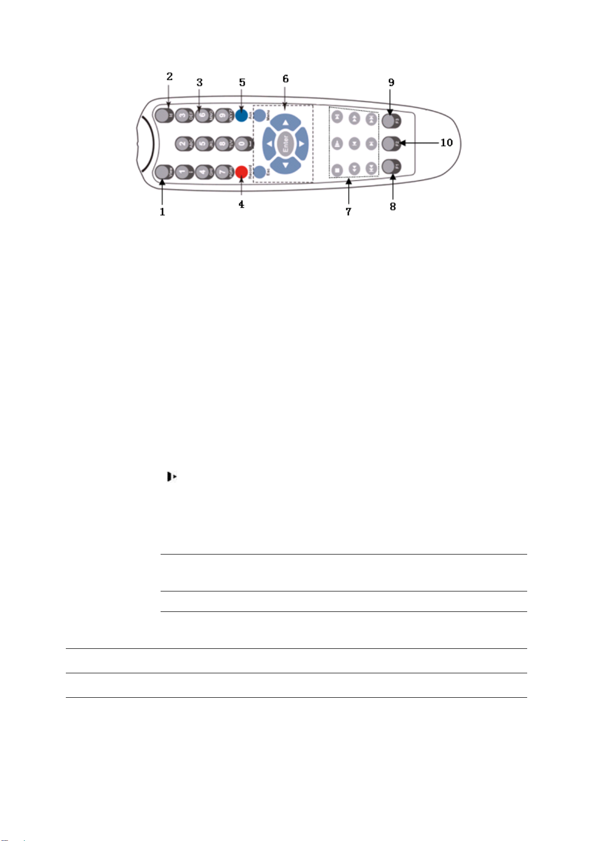
Figure 2-2
SN Name Function
1 View Video switch
2 ID Press this button and then input DVR serial
number to control this DVR
3 Numeral 0-9 number key. You can input password,
numeral or switch channel
4 Record Record video
5 Aux Auxiliary key
6
7
Enter Confirm /menu key
Menu Pop up menu
Esc Cancel
S
W X
T
│_
Direction keys
Direction keys in PTZ control
Stop
Zoom- in PTZ control
Slow play
Playback/Pause
Zoom + in PTZ control
Backward
Previous section
Forward
f│
8
9
10 F3 Reserved for future use
F1 One-key backup button
F2 Reserved for future use
Slow forward: Various slow play speeds and normal
Playback mode.
Focus- in PTZ control
Next section
Fast forward: Various fast forward speeds and normal
playback mode.
Focus + in PTZ control
2.3 Mouse Control
11
Page 12
Left click
mouse
System pops up password input dialogue box if you have not logged in.
In real-time monitor mode, you can go to the main menu.
When you have selected one menu item, left click mouse to view menu
content.
Implement the control operation.
Modify checkbox or motion detection status.
Click combo box to pop up drop down list
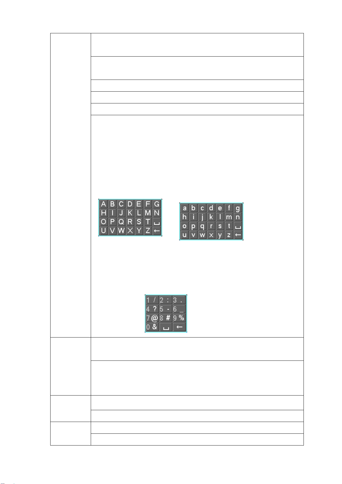
In input box, you can select input methods. Left click the corresponding
button on the panel you can input numeral/English character
(small/capitalized). Here ← stands for backspace button. _ stands for space
button.
In English input mode: _stands for input a backspace icon and ← stands for
deleting the previous character.
Double left
click mouse
Right click
mouse
In numeral input mode: _ stands for clear and ← stands for deleting the
previous numeral.
When input special sign, you can click corresponding numeral in the front
panel to input. For example, click numeral 1 you can input“/” , or you can click
the numeral in the on-screen keyboard directly.
Implement special control operation such as double click one item in the file
list to playback the video.
In multiple-window mode, double left click one channel to view in full-window.
Double left click current video again to go back to previous multiple-window
mode.
Exit main menu and go to the preview interface.
Exit current menu without saving the modification.
middle
In numeral input box: Increase or decrease numeral value. Press
Switch the items in the check box.
12
Page 13

button Page up or page down
Move
mouse
Select current control or move control
Select motion detection zone Drag mouse
Select privacy mask zone.
13
Page 14

3 Installation and Connections
Note: All the installation and operations here should conform to your local
electric safety rules.
3.1 Check Unpacked DVR
When you receive the DVR from the shipping agency, please check whether there is
any visible damage to the DVR appearance. The protective materials used for the
package of the DVR can protect most accidental clashes during transportation. Then
you can open the box to check the accessories.
Please check the items in accordance with the list on the warranty card. Finally you
can remove the protective film of the DVR.
3.2 Device installation
Please refer to Vehicle DVR Installation Manual.
14
Page 15
4 Overview of Navigation and Controls
Before operation, please make sure you have properly installed HDDs and all the
cable connections.
4.1 Login, Logout & Main Menu
4.1.1 Login
Turn the key to ACC, you can see power indication light becomes on and DVR boots
up (DVR boots up might take several seconds). System is in multiple-window
preview mode after boots up and record setup is continuous record mode. You can
see corresponding channel indication light becomes on and record indication light
becomes on too.
After the system boots up, default video display is in multiple-window mode.
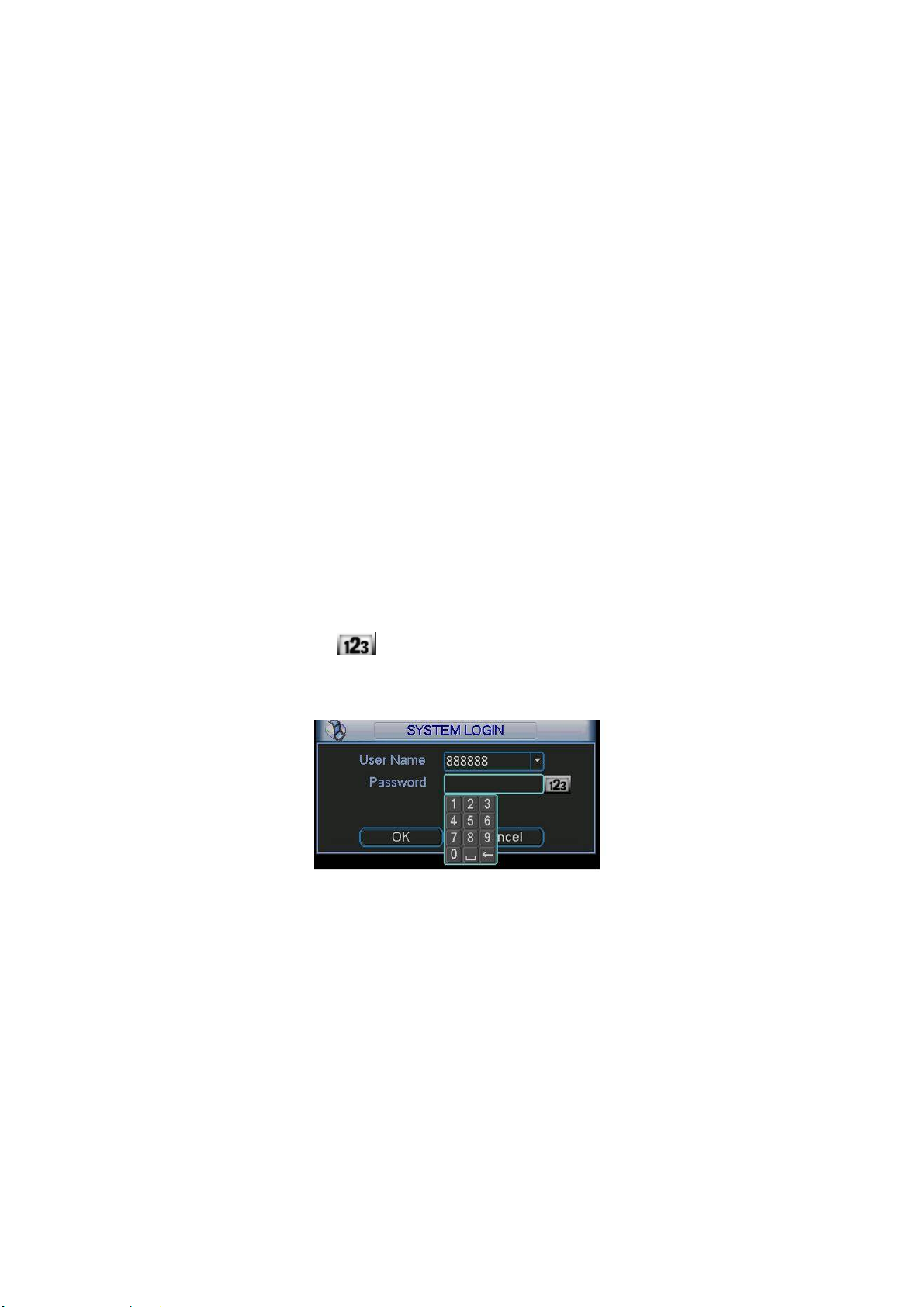
Click Enter or left click mouse, you can see the login interface. See Figure 4-1.
System consists of four accounts:
z Username: admin. Password: admin. (administrator, local and network)
z Username: 888888. Password: 888888. (administrator, local only)
z Username: 666666. Passwords: 666666(Lower authority user who can only
monitor, playback, backup and etc.)
z Username: default. Password: default(hidden user)
For your system security, please modify you password after first login.
You can use USB mouse, front panel, remote controller or keyboard to input.
About input method: Click to switch between numeral, English character
(small/capitalized) and denotation.
Figure 4-1
4.1.2 Main Menu
When you logged in, the system main menu is shown as below. See
There are total six icons: search, information, setting, backup, advanced and
shutdown. Move the cursor to highlight the icon, then left click mouse to enter the
sub-menu.
Figure 4-2.
15
Page 16
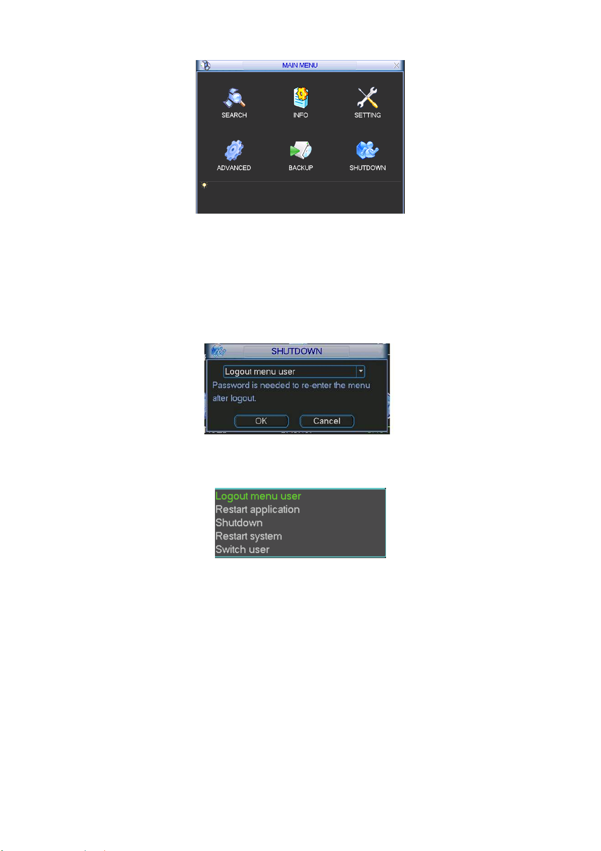
Figure 4-2
4.1.3 Logout
There are two ways for you to log out.
One is from menu option:
In the main menu, click shutdown button, you can see an interface is shown as
below. See
Figure 4-3.
Figure 4-3
There are several options for you. See Figure 4-4.
Figure 4-4
The other way is to press power button on the front panel for at least 3 seconds,
system will stop all operations. Then you can click the power button in the rear
panel to turn off the DVR.
System supports ACC delaying function. The value ranges from 0 to 255(Unit:
minute). System can delay shutting down for the specified time and then turn off.
4.1.4 Auto Resume after Power Failure
The system can automatically backup video and resume previous working status
after power failure.
4.2 Recording Operation
4.2.1 Live Viewing
16
Page 17
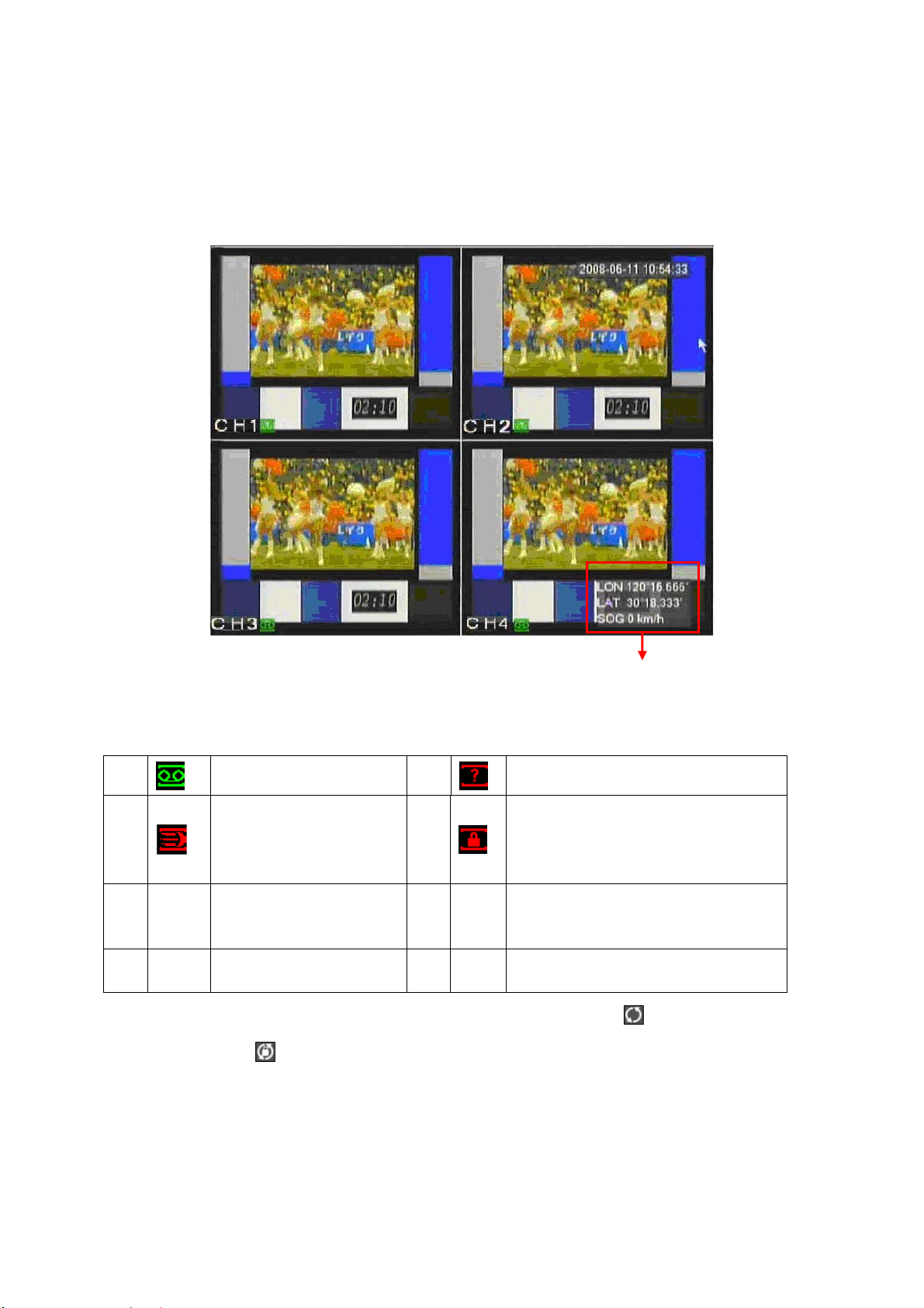
After you logged in, the system is in live viewing mode. You can see system date,
time and channel name. Here you can also view longitude, latitude and vehicle
speed.
If you want to change system date and time, you can refer to general settings
(Main Menu->Setting->General). If you want to change the channel name, please
refer to the display settings (Main Menu->Setting->Display). See Figure 4-4.
Longitude/latitude and vehicle speed
Figure 4-5
1
2
5 LON
SOG
7
Recording status
Motion detection
longitude
Vehicle speed
3
4
6 LAN
Video loss
Camera lock
Latitude
Note: Please refer to the following sheet for channel status. stands for opening
switch function, stands for closing switch function.
4.2.2 Manual record Note:
You need to have proper rights to implement the following operations. Please
make sure the HDDs have been properly installed.
4.2.2.1 Manual record menu There are two ways for you to go to manual record menu.
17
Page 18
z Right click mouse or in the main menu, Advanced->Manual Record.
z In live viewing mode, click record button in the front panel or record button in the
remote control.
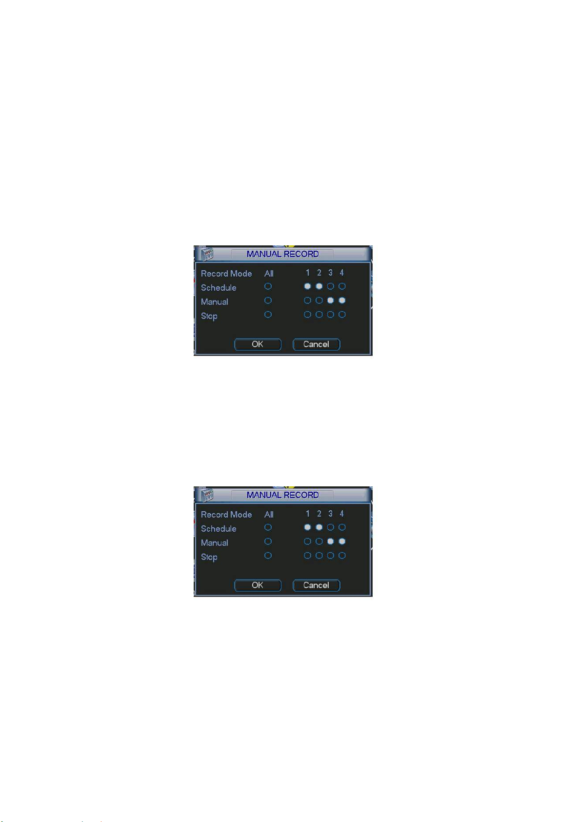
Manual record menu is shown as in Figure 4-6.
4.2.2.2 Basic operation There are three statuses: schedule/manual/stop. Highlight icon“○” to select corresponding channel. z Manual: the highest priority. After manual setup, all selected channels will begin
ordinary recording.
z Schedule: channel records as you have set in recording setup (Main Menu-
>Setting->Schedule)
z Stop: all channels stop recording.
Figure 4-6
4.2.2.3 Enable/disable record
Please check current channel status: “○” means it is not in recording status,
“●” means it is in recording status.
You can use mouse or direction key to highlight channel number. See Figure 4-7.
Figure 4-7
4.2.2.4 Enable all channel recording
Highlight ○ below All, you can enable all channel recording.
z All channel schedule record
Please highlight “ALL” after “Schedule”. See Figure 4-8.
When system is in schedule recording, all channels will records as you have
previously set (Main menu->Setting->Schedule).
The corresponding indication light in front panel will turn on.
18
Page 19
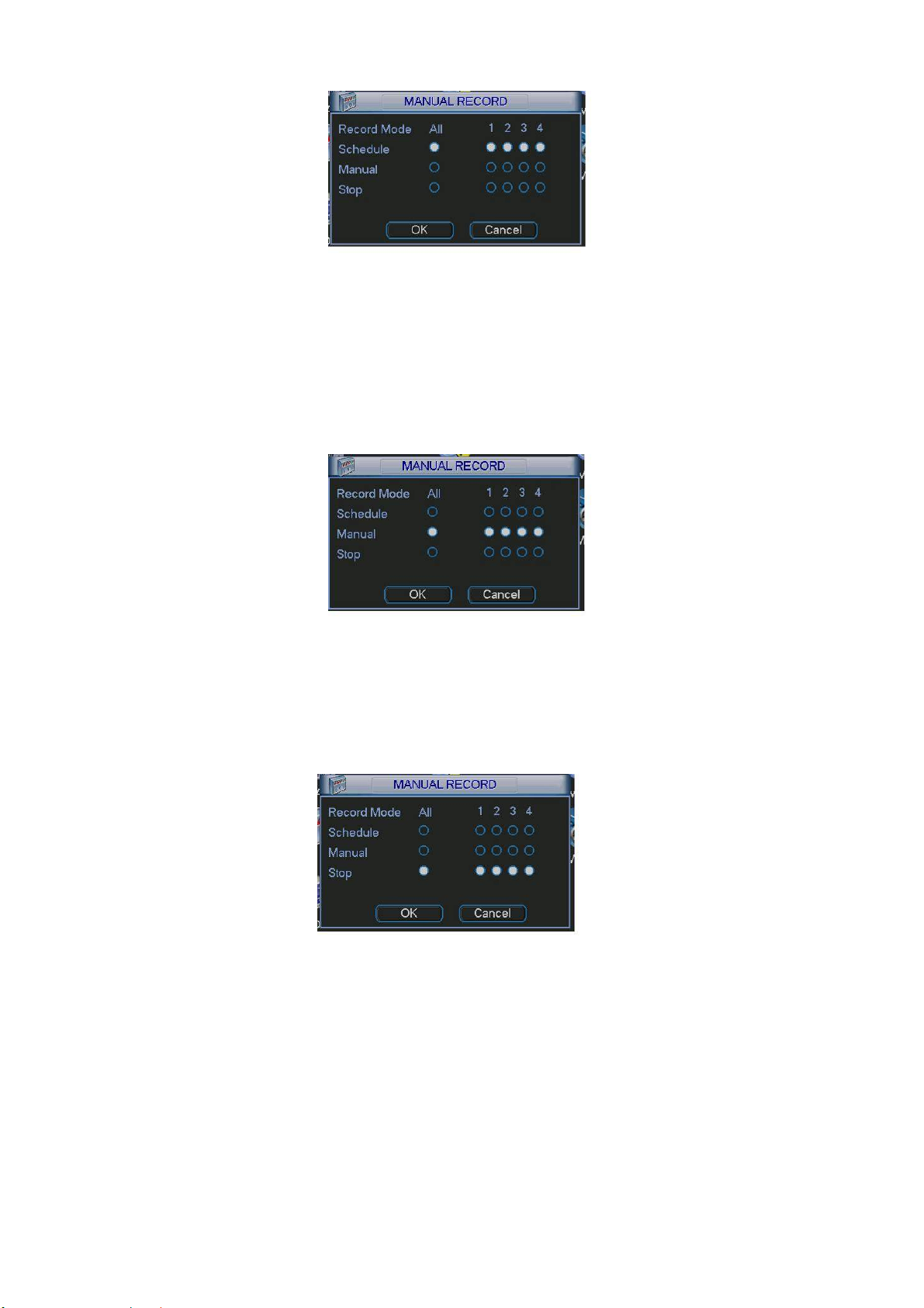
Figure 4-8
z All channel manual record
Please highlight “ALL” after “Manual.” See Figure 4-9.
When system is in manual recording, all scheduled set up you have set in will be
null ((Main menu->Setting->Schedule)).
You can see indication light in front panel turns on, system begins manual record
now.
Figure 4-9
4.2.2.5 Stop all channel recording Please highlight “ALL” after “Stop”. See Figure 4-10. System stops all channel recording no matter what mode you have set in the menu (Main menu->Setting->Schedule)
Figure 4-10
4.3 Search & Playback
4.3.1 Search Menu
There are two ways for you to go to search menu.
z Click Pause/Play button in the remote control.
z Click search in the main menu.
Search interface is shown as below. See Figure 4-11.
Usually there are three file types:
19
Page 20
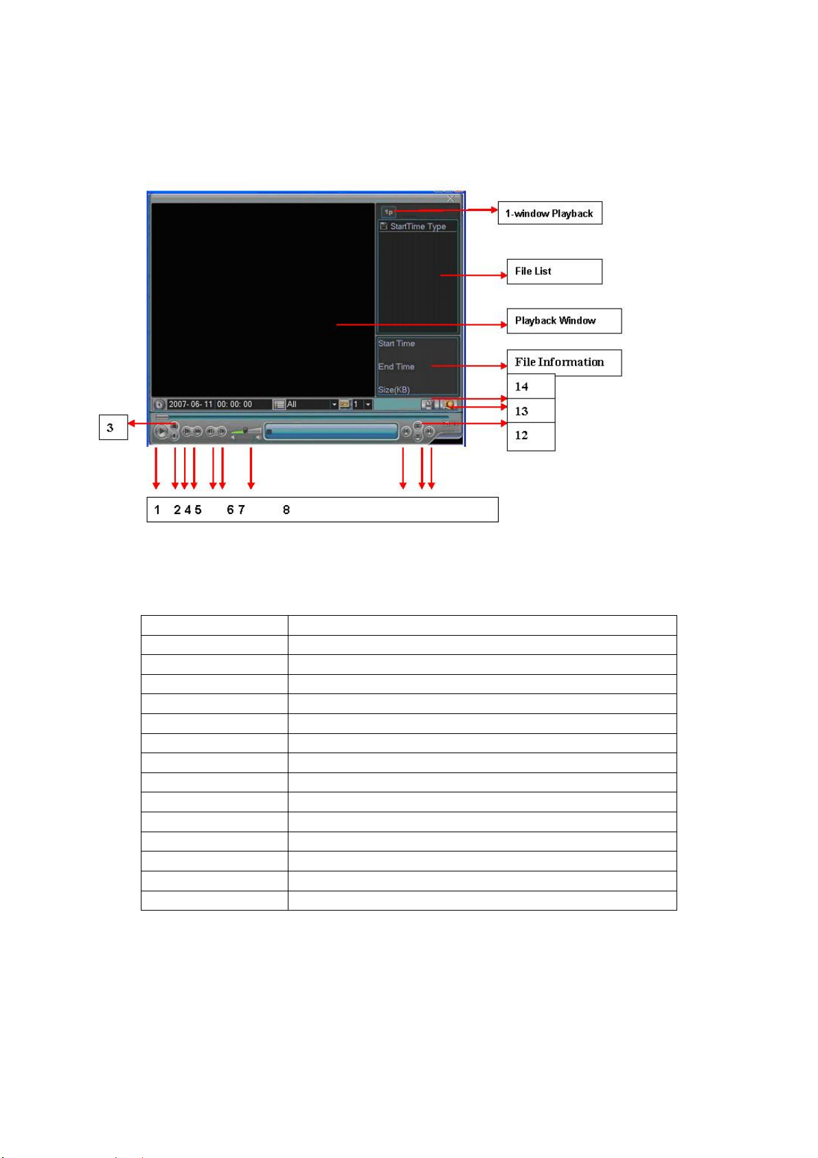
z R: regular recording file.
z A: external alarm recording file.
z M: motion detection recording file
There are several playback windows. This System supports 1-ch playback.
Figure 4-11
Please refer to the following sheet for more information.
Serial Number Function
1 Play
2 Backward
3 Stop
4 Slow play
5 Fast play
6 Previous frame
7 Next frame
8 Volume
9 Previous file
10 Next channel
11 Next file
12 Previous channel
13 Search
14 Backup
4.3.2 Basic Operation
4.3.2.1 Playback There are various search modes: video type, channel number or time. The system can max display 128 files in one screen. You can use up/down button to turn page.
20
Page 21
Select the file name and double click mouse (or click enter button), you can view
file content.
4.3.2.2 Accurate playback Input time (h/m/s) in the time column and then click playback button, system can operate accurate playback.
4.3.2.3 Synchronized playback function when playback During playback process, click numeral key, system can switch to the corresponding channel video of the same time.
4.3.2.4 Digital zoom When the system is in full-screen playback mode, drag your mouse in the screen to select a section and then left click mouse to realize digital zoom. You can right click mouse to exit.
4.3.2.5 File backup System supports backup operation during search. You can draw a √ before file name (multiple choices). Then click backup button (Button 14 in Figure 4-11). Note: All the operations here (such as playback speed, channel, time and progress) have relationship with hardware version. Some series DVRs do not support some functions or playback speeds.
4.4 Record Setup (Schedule)
When the system boots up, it is in default 24-hour regular mode. You can set
record type and time in schedule interface.
4.4.1 Schedule Menu
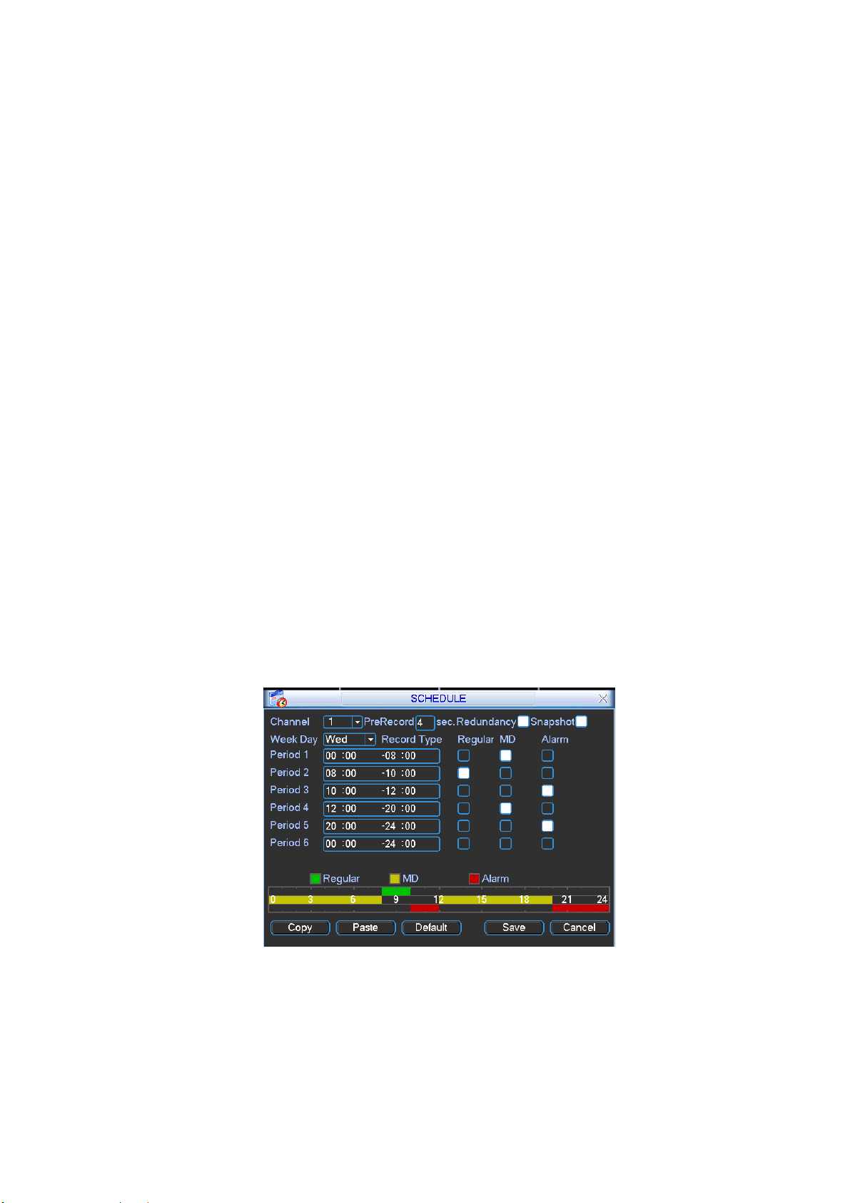
In the main menu, from setting to schedule, you can go to schedule menu. See
Figure 4-12.
There are three record types: R-Regular, MD-Motion detection, A- Alarm.
Figure 4-12
4.4.2 Basic Operation
There are total six periods. See Figure 4-12.
z Channel: Please select the channel number first. You can select “all” if you want
to set for the whole channels.
z Week day: There are eight options: ranges from Saturday to Sunday and all.
21
Page 22

z Redundancy: System supports redundancy backup function. You can highlight
Redundancy button to activate this function. Please note, before enable this
function, please set at least one HDD as redundant. Refer to the manual for
detailed information.
z Prerecord: System supports prerecord function. The previous one to three
seconds video before alarm occurs can be included in recorded video.
z Snapshoot: You can enable this function to snapshoot image when alarm occurs.
z Record types: There are three types: regular, motion detection (MD) and Alarm.
Please highlight icon to select the corresponding function. After all the setups
please click save button, system goes back to the previous menu.
At the bottom of the menu, there is a color bar for your reference. Green stands
for regular recording, yellow stands for motion detection and red stands for alarm
recording.
4.4.1.1 Quick Setup This function allows you to copy one channel setup to another. After setting in channel 1, you can click paste button and turn to channel 2 and then click copy button. You can finish setting for one channel and then click save button or you can finish all setup and then click save button to memorize all the settings.
4.4.1.2 Redundancy Redundancy function allows you to memorize record file in several disks. These files are created, packaged and closed simultaneously. When there is file damage occurred in one disk, there is a spare one in the other disk. You can use this function to maintain data reliability and safety. In the main menu, from Setting to Schedule, you can highlight redundancy button to enable this function. See Figure 4-12. In the main menu, from Advanced to HDD management, you can set one or more disk(s) as redundant. You can select from the dropdown list. See Figure 4-13. System auto overwrites old files once hard disk is full. Please note only read/write disk or read-only disk can backup file and support file search function, so you need to set at least one read-write disk otherwise you can not record video.
Note:
About redundancy setup please note:
z If current channel is not recording, current setup gets activated when the channel
begin recording the next time.
z If current channel is recording now, current setup will get activated right away, the
current file will be packet and form a file, then system begins recording as you
have just set.
After all the setups please click save button, system goes back to the previous
menu.
22
Page 23

Figure 4-13
Playback or search in the redundant disk.
There are two ways for you to playback or search in the redundant disk.
z Set redundant disk(s) as read-only disk or read-write disk (Main menu-
>Advanced->HDD management). See Figure 4-13.System needs to reboot to get
setup activated. Now you can search or playback file in redundant disk.
z Dismantle the disk and play it in another PC.
4.5 Detect
4.5.1 Go to Detect Menu
In the main menu, from Setting to Detect, you can see motion detect interface.
See Figure 4-14.
4.5.2 Detect
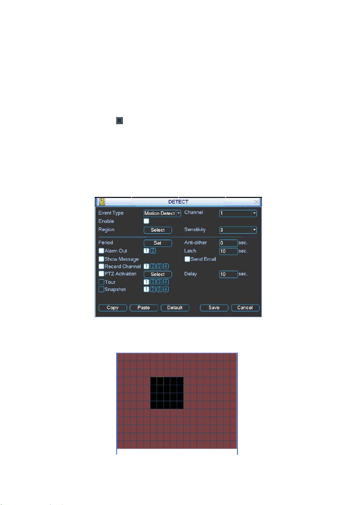
Detection menu is shown as below. See Figure 4-14.
z Channel: select the channel you want to implement motion detection.
z Event type: from the dropdown list you can select motion detection type.
z Channel: select the channel to activate recording function once alarm occurred.
Please make sure you have set MD record in encode interface(Main Menu>Setting->Schedule) and schedule record in manual record interface(Main Menu>Advanced->Manual Record)
z Latch: when motion detection completed, system auto delays detecting for a
specified time. The value ranges from 10-300(Unit: second)
z Region: Click select button, the interface is shown as in
set motion detection zone. There are 396(PAL)/330(NTSC) small zones.
z Sensitivity: System supports 6 levels. The sixth level has the highest sensitivity.
z Show message: System can pop up a message to alarm you in the local host
screen if you enabled this function.
z Send email: System can send out email to alert you when alarm occurs.
z PTZ activation: Here you can set PTZ movement when alarm occurs. Such as go
to preset, tour &pattern when there is an alarm. Click “select” button, you can see
an interface is shown as in
z Period: Click set button, you can see an interface is shown as in Figure 4-17.
Here you can set for business day and non-business day. In Figure 4-17, click set
Figure 4-16.
Figure 4-15.Here you can
23
Page 24
button, you can see an interface is shown as in Figure 4-18. Here you can set
your own setup for business day and non-business day.
z Anti-dither: Here you can set anti-dither time.
z Sensitivity: there are six levels. The sixth level has the highest sensitivity.
z Alarm output: when alarm occurred, system enables peripheral alarm devices.
z Tour: Here you can enable tour function when alarm occurs. It is a one-window
tour. Please go to chapter 5.3.9 Display for tour interval setup.
z Snapshot: System can snapshoot when alarm occurs.
Please highlight icon to select the corresponding function. After all the setups
please click save button, system goes back to the previous menu.
Note:
In motion detection mode, you can not use copy/paste to set channel setup since the
video in each channel may not be the same.
In Figure 4-15, you can left click mouse and then drag it to set a region for motion
detection. Click Fn to switch between arm/withdraw motion detection. After setting,
click enter button to exit.
Figure 4-14
Figure 4-15
24
Page 25
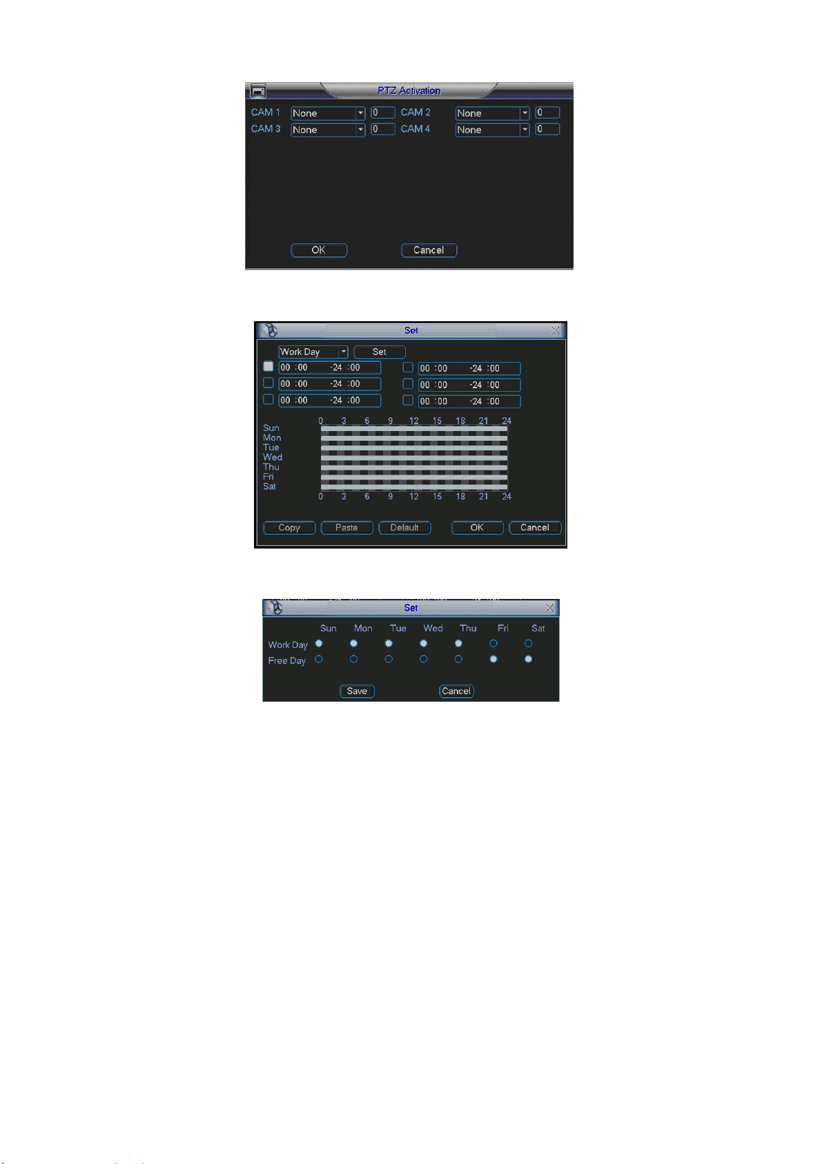
Figure 4-16
Figure 4-17
Figure 4-18
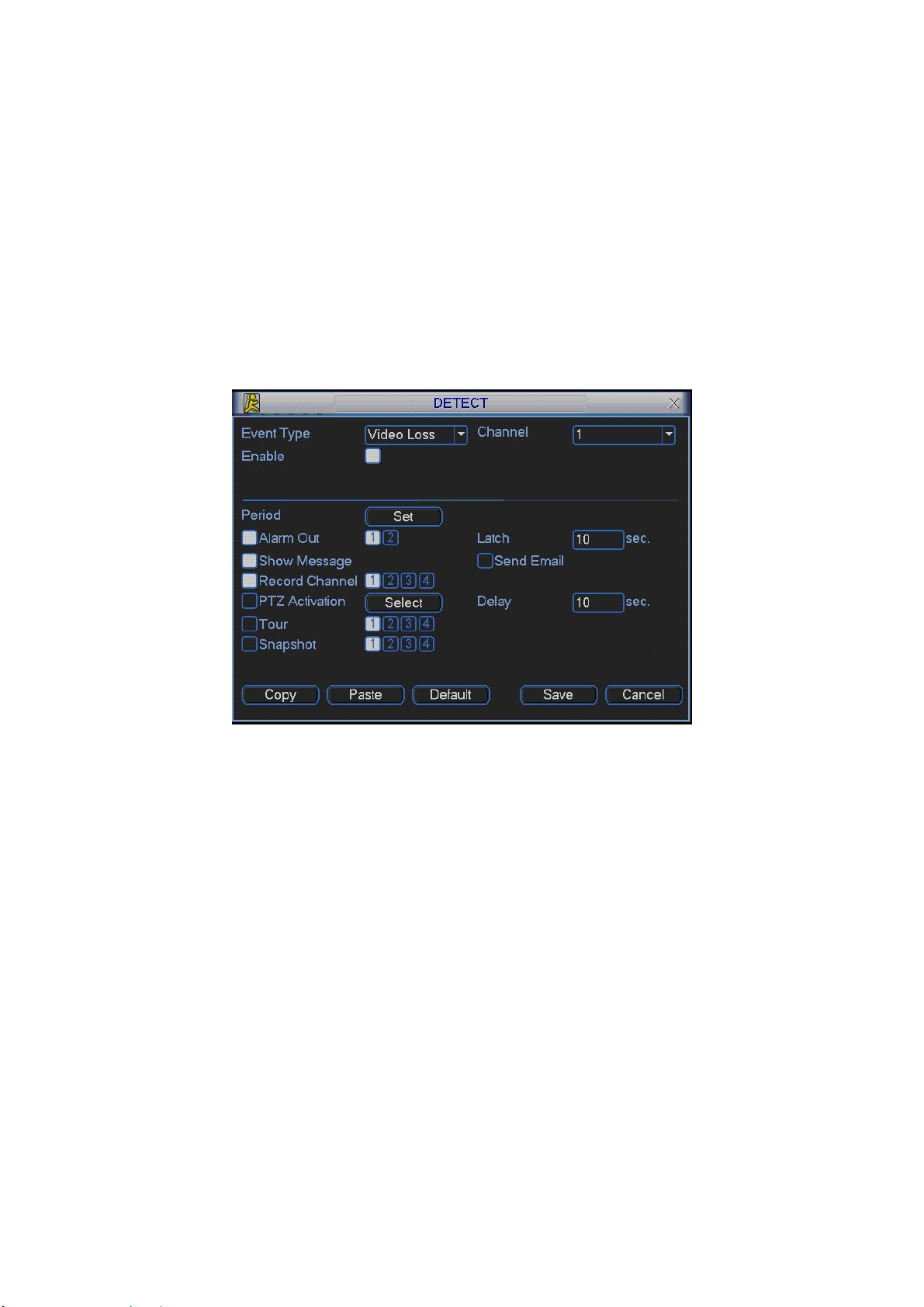
4.5.3 Video Loss
In Figure 4-14, select video loss in the Type item. You can see the interface is
shown as in
phenomenon occurred. You can enable alarm output channel and then enable
show message function.
z Channel: select the channel you want to enable lens shading alarm.
z Event type: please select video loss.
z Channel: select the channel to record when video loss occurred.
z Alarm output: activate peripheral alarm device when video loss occurred.
z Latch: when motion detection complete, system auto delays detecting for a
specified time. The value ranges from 10-300(Unit: second)
z Show message: System can pop up a message to alarm you in the local host
screen if you enabled this function.
z Send email: System can send out email to alert you when alarm occurs.
Figure 4-19.This function allows you to be informed when video loss
25
Page 26
z PTZ activation: Here you can set PTZ movement when alarm occurs. Such as go
to preset, tour & pattern when there is an alarm. Click “select” button, you can
see an interface is shown as in Figure 4-16.
z Period: Click set button, you can see an interface is shown as in Figure 4-17.
Here you can set for business day and non-business day. In Figure 4-17, click set
button, you can see an interface is shown as in Figure 4-18. Here you can set
your own setup for business day and non-business day.
z Sensitivity: there are six levels. The sixth level has the highest sensitivity.
z Alarm output: when alarm occurred, system enables peripheral alarm devices.
z Tour; Here you can enable tour function when alarm occurs. It is a one-window
tour. Please go to chapter 5.3.9 Display for tour interval setup.
z Snapshot: System can snapshoot when alarm occurs.
Figure 4-19
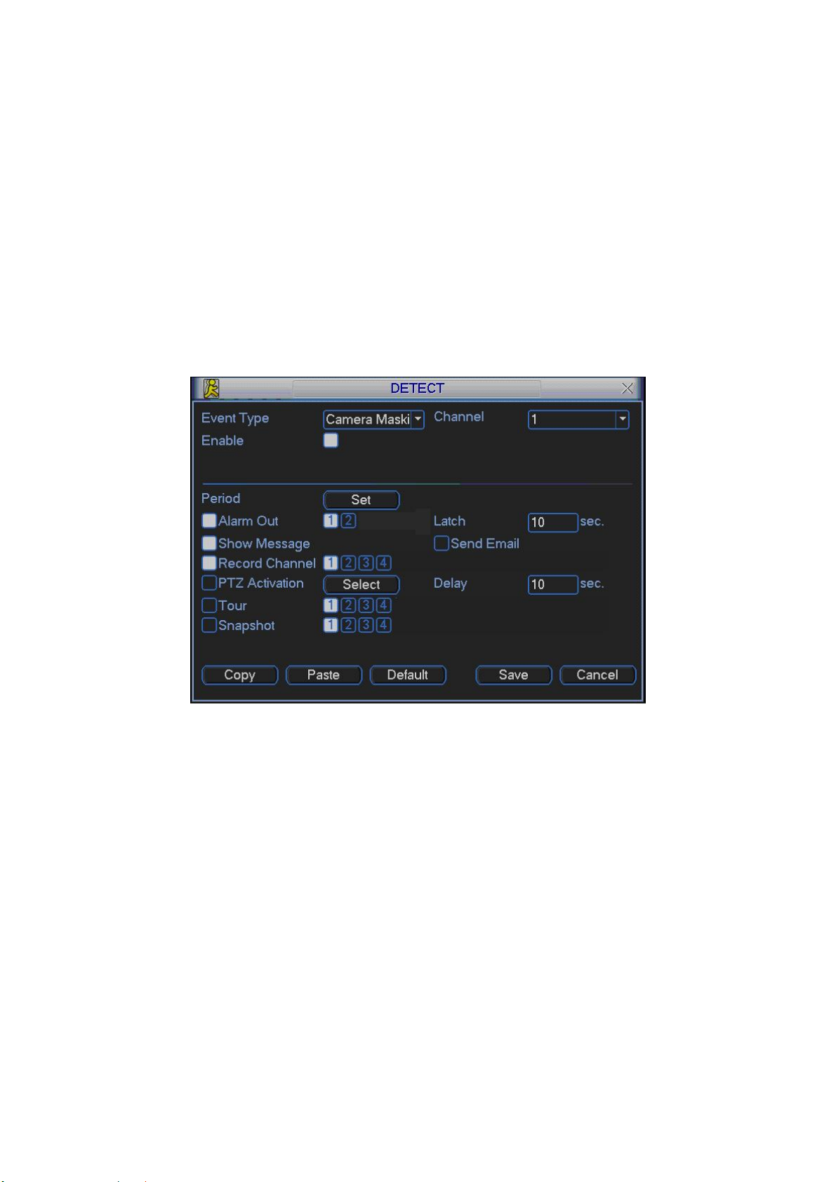
4.5.4 Camera Mask Detect
When someone viciously masks lens, the system can alert you to guarantee video
continuity. Camera mask detection interface is shown as in Figure 4-20.
z Channel: select the channel you want to enable camera mask detection function.
z Event type: please select camera mask detect from the dropdown list.
z Channel: select the channel to record when camera mask occurred.
z Alarm output: activate peripheral alarm device when camera mask occurred.
z Enable tour: Here is for you to activate tour between different cameras.
z Latch: when motion detection complete, system auto delays detecting for a
specified time. The value ranges from 10-300(Unit: second)
z Show message: System can pop up a message to alarm you in the local host
screen if you enabled this function.
z Send email: System can send out email to alert you when alarm occurs.
z PTZ activation: Here you can set PTZ movement when alarm occurs. Such as go
to preset, tour &pattern when there is an alarm. Click “select” button, you can see
an interface is shown as in Figure 4-16.
26
Page 27
z Period: Click set button, you can see an interface is shown as in Figure 4-17.
Here you can set for business day and non-business day. In Figure 4-17, click set
button, you can see an interface is shown as in Figure 4-18. Here you can set
your own setup for business day and non-business day.
z Sensitivity: there are six levels. The six-level has the highest sensitivity.
z Alarm output: when alarm occurred, system enables peripheral alarm devices.
z Tour: Here you can enable tour function when alarm occurs. It is a one-window
tour: Please go to chapter 5.3.9 Display for tour interval setup.
z Snapshoot: System can snapshoot when alarm occurs.
Note:
In this interface, copy/paste function is only valid for the same type, which means
you can not copy a channel setup in video loss mode to camera mask detect
mode.
Figure 4-20
4.6 Alarm Setup and Alarm Activation
Before operation, please make sure you have properly connected alarm devices
such as buzzer.
4.6.1 Go to alarm setup interface
In the main menu, from Setting to Alarm, you can see alarm setup interface. See
Figure 4-21.
4.6.2 Alarm setup
Alarm interface is shown as below. See
z Alarm in: here is for you to select channel number.
z Event type: there are two types. One is local input and the other is network input.
z Type: normal open or normal close.
Figure 4-21.
27
Page 28
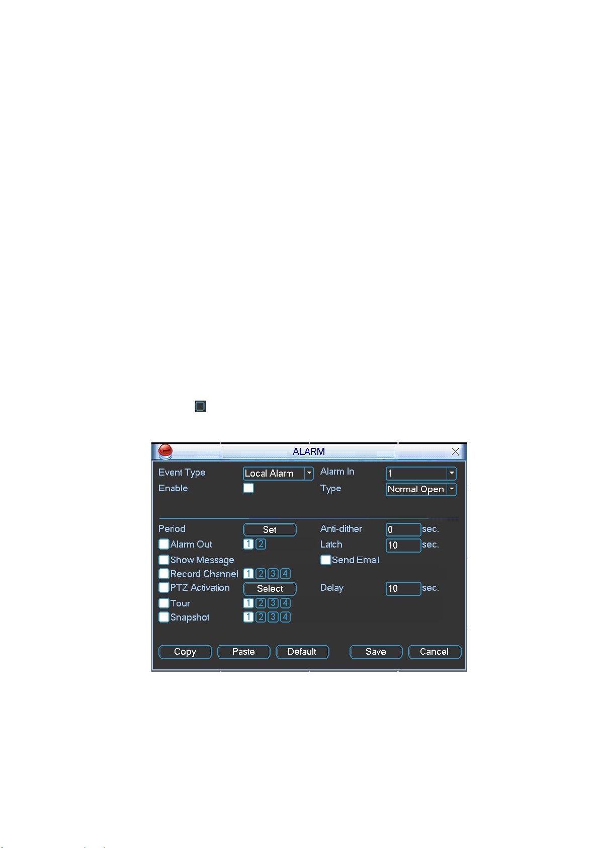
z PTZ activation: Here you can set PTZ movement when alarm occurs. Such as go
to preset, tour& pattern when there is an alarm. Click “select” button, you can see
an interface is shown as in Figure 4-25.
z Period: Click set button, you can see an interface is shown as in Figure 4-23.
Here you can set for business day and non-business day. In Figure 4-23, click set
button, you can see an interface is shown as in Figure 4-24. Here you can set
your own setup for business day and non-business day.
z Anti-dither: Here you can set anti-dither time.
z Show message: System can pop up a message to alarm you in the local host
screen if you enabled this function.
z Send email: System can send out email to alert you when alarm occurs.
z Record channel: you can select proper channel to record alarm video (Multiple
choices). At the same time you need to set alarm record in schedule interface
(Main Menu->Setting->Schedule) and select schedule record in manual record
interface (Main Menu->Advance->Manual Record).
z Latch: Here is for you to set proper delay duration. Value ranges from 10 to 300
seconds. System automatically delays specified seconds in turning off alarm and
activated output after external alarm cancelled.
z Tour: Here you can enable tour function when alarm occurs. It is a one-window
tour: Please go to chapter 5.3.9 Display for tour interval setup.
z Snapshot: System can snapshoot when alarm occurs.
Please highlight icon to select the corresponding function. After completed all
the setups please click save button, system goes back to the previous menu.
Figure 4-21
28
Page 29
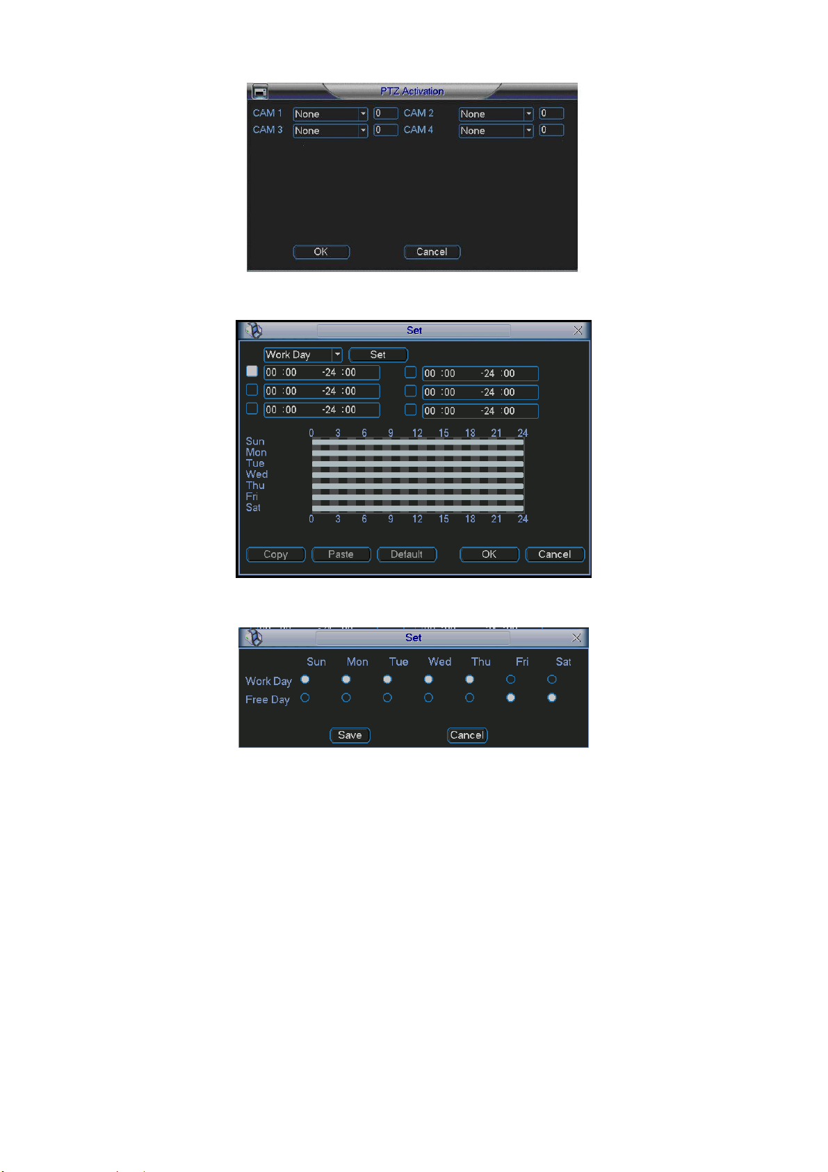
Figure 4-22
Figure 4-23
Figure 4-24
4.7 Backup
Click backup icon in the main menu, there are two function items: detect device
and backup files.
This series DVR support can realize file backup via USB port. Usually the USB
backup device format is FAT32. In one-key backup function, the file is in the first
sub-area.
4.7.1 Detect Device
Here is for you to view devices information. See Figure 4-25.
The backup device can be flash disk or portable device. Here you can also view
device total space and free space.
29
Page 30
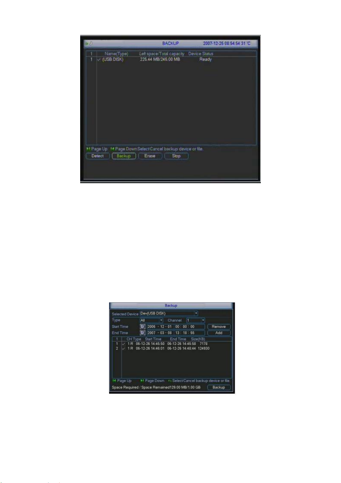
Figure 4-25
4.7.1 Backup (Including one-button backup)
Select backup device and then channel, file start time and end time.
Click add button, system begins search. All matched files are listed below.
System automatically calculates the capacity needed and remained. See Figure
4-26.
system only backup files with a √ before channel name. You can use Fn or
cancel button to delete √ after file serial number.
Click backup button, you can backup selected files. There is a process bar for you
reference.
When the system completes backup, you can see a dialogue box prompting
successful backup.
Figure 4-26
Click backup button, system begins burning. At the same time, the backup button
becomes stop button. You can view the remaining time and process bar at the left
bottom. See Figure 4-27.
30
Page 31

Figure 4-27
Tips:
During backup process, you can click ESC to exit current interface; but the
system will not terminate backup process.
Note:
When you click stop button during the burning process, system can backup the data
before you click stop button. For example, if there are ten files, you click stop when
backup the fifth file, system only save the previous five file data in the device. But you
can still see ten file names
The file name format usually is: SN_CH+channel number+time Y+M+D+H+M+S.
In the file name, the YDM format is the same as you set in general interface.
(Main Menu ->Setting ->General).
4.7.1.1 One-key backup function When there is no displayer connected, you can use one-key backup function. See Figure 4-28.
Figure 4-28
Please follow the steps listed below.
z Default backup day is 1 day.
z Click the F1 button in the remote control, you can see one-key backup
interface. The initial progress bar is 0%. If system meets all the conditions,
system automatically begin backup.
z If you want to terminate the backup during the whole process, you can click
“stop” button and then remove backup device.
31
Page 32

Backup up status and corresponding prompts.
When there is no backup operation. Backup indication light (LED6) is off. During
the backup process, the indication light (LED6) flashes. The indication light (LED6)
is on after successfully completed the backup.
Importance Notice:
z Please insert backup device when system is working properly.
z Once starting back up, do not remove the backup device during the
whole process. It may result in file damage or USB device malfunction.
z After completed backup, please remove the backup device and then turn
off the power or shut down the system.
4.8 PTZ Control and Color Setup
Note: All the operation here is based on PELCO protocols. For other protocols,
there might be a little difference.
4.8.1 Cable Connection
Please follow the procedures below to go on cable connection
z Connect the dome RS485 port to DVR 485 port..
z Connect dome video output cable to DVR video input port.
z Connect power adapter to the dome.
4.8.2 PTZ Setup
Note: The camera video should be in the current screen. Before setup, please
check the following connections are right:
z PTZ and decoder connection is right. Decoder address setup is right.
z Decoder A (B) line connects with DVR A (B) line.
Boot up the DVR, input user name and password.
In the main menu, click setting, and then click Pan/Tilt Control button. The
interface is shown as in Figure 4-29. Here you can set the following items:
z Channel: select the current camera channel.
z Protocol: select corresponding PTZ protocol(such as PELCO)
z Address: default address is 1.
z Baud rate: select corresponding baud rate. Default value is 115200.
z Data bits: select corresponding data bits. Default value is 8.
z Stop bits: select corresponding stop bits. Default value is 1.
z Parity: there are three options: odd/even/none. Default setup is none.
32
Page 33

Figure 4-29
After completed all the setups please click save button.
In one window display mode, right click mouse (click “Fn” Button in the front panel
or click “Fn” key in the remote control). The interface is shown as in Figure 4-30.
Figure 4-30
Click Pan/Tilt/Zoom, the interface is shown as below. See
Here you can set the following items:
z Step: value ranges fro 1 to 8.
z Zoom
z Focus
z Iris
Click icon
and to adjust zoom, focus and iris.
Figure 4-31.
33
Page 34

Figure 4-31
In Figure 4-31, please click direction arrows (See Figure 4-32) to adjust PTZ position.
There are total 8 direction arrows.
Figure 4-32
4.8.3 3D Intelligent Positioning Key
In the middle of the eight direction arrows, there is a 3D intelligent positioning key.
See Figure 4-33.
Click this key, system goes back to the single screen mode. Drag the mouse in the
screen to adjust section size. It can realize PTZ automatically.
Figure 4-33
Here is a sheet for you reference.
Name Function
key
Zoom
Focus
Iris
function Shortcut
key
Near ►
Near
close
_
W
Function
key
function Shortcut
Key
Far
Far
Open
►
f
4.9 Preset/ Patrol/Pattern/Scan
In Figure 4-31, click the “set” button. The interface is shown as below. See Figure
4-34.
Here you can set the following items:
z Preset
z Tour
z Pattern
z Border
Figure 4-34
In Figure 4-31, click page switch button, the interface is shown as in Figure 4-35.
34
Page 35

Here you can activate the following functions:
z Preset
z Tour
z Pattern
z Auto scan
z Auto pan
z Flip
z Reset
z Page switch
Figure 4-35
Note: The following setups are usually operated in the Figure 4-31,Figure 4-34 and
Figure 4-35 .
4.9.1Preset Setup
In Figure 4-31, use eight direction arrows to adjust camera to the proper position.
In Figure 4-34, click preset button and input preset number. The interface is shown
as in Figure 4-36.
Now you can add this preset to one tour.
Figure 4-36
4.9.2 Activate Preset
In Figure 4-35, please input preset number in the No. blank, and click preset button.
4.9.3 Patrol setup (Tour Setup)
Figure 4-34, click patrol button. The interface is shown as in Figure 4-37.Input
In
preset number and add this preset to a patrol (tour). For each patrol (tour), you can
input max 80 presets.
35
Page 36

Figure 4-37
4.9.4 Activate Patrol (tour)
In Figure 4-34, input patrol (tour) number in the No. blank and click patrol button
4.9.5 Pattern Setup
In Figure 4-34, click pattern button and then click “begin” button. The interface is
shown as in Figure 4-38. Then you can go to Figure 4-31 to modify zoom, focus, and
iris.
Go back to Figure 4-38 and click “end” button. You can memorize all these
operations as pattern 1.
Figure 4-38
4.9.6 Activate Pattern Function
In Figure 4-35, input mode value in the No. blank, and click pattern button.
4.9.7 Auto Scan Setup
In Figure 4-34, click border button. The interface is shown as in Figure 4-39
Please go to
Then please go to
Repeat the above procedures to set right limit.
Figure 4-31, use direction arrows to select camera left limit
Figure 4-39 and click left limit button
Figure 4-39
36
Page 37

4.9.8 Activate Auto Scan
In Figure 4-35, click “Auto Scan” button, the system begins auto scan.
Correspondingly, the auto scan button becomes to stop button. Click stop button to
terminate scan operation.
4.10 Flip
In Figure 4-35, click page switch button, you can see an interface is shown as below.
See Figure 4-40. Here you can set auxiliary function.
Click page switch button again, system goes back to Figure 4-31.
Figure 4-40
37
Page 38

5 Understanding of Menu Operations and Controls
5.1 Menu Tree
This series DVR menu tree is shown as below.
5.2 Main Menu
After you logged in, the system main menu shows as below. See Figure 5-1 . There
are total six icons: search, Information, setting, backup, advanced and shutdown.
Move the cursor to highlight the icon, then double click mouse to enter the sub-menu.
38
Page 39

Figure 5-1
5.3 Setting
In main menu, highlight setting icon and double click mouse. System setting
interface is shown as below. See Figure 5-2.
Figure 5-2
5.3.1 General
General setting includes the following items. See Figure 5-3.
z System time: here is for you to set system time
z Date format: there are three types: YYYYY-MM-DD: MM-DD-YYYYY or DD-MM-
YYYY.
z Date separator: there are three denotations to separate date: dot, beeline and
solidus.
z Snapshot: Here you can set image upload interval.
z DST: Here you can set DST time and date. Please enable DST function and then
click set button. You can see an interface is shown as in Figure 5-4. Here you can
set start time and end time by setting corresponding week setup. In Figure 5-4,
enable date button, you can see an interface is shown as in Figure 5-5. Here you
can set start time and end time by setting corresponding date setup.
z Time format: there are two types: 24-hour mode or 12-hour mode.
z Language: system supports various languages: Chinese (simplified), Chinese
(Traditional), English, Italian, Japanese, French, Spanish (All languages listed
here are optional. Slight difference maybe found in various series.)
39
Page 40

z HDD full: Here is for you to select working mode when hard disk is full. There are
two options: stop recording or rewrite.
z Pack duration: Here is for you to specify record duration. Default value is 60
minutes.
z DVR No: when you are using one remote control to control several DVRs, you
can give a name to each DVR for your management.
z Video standard: There are two formats: NTSC and PAL.
z Auto logout: Here is for you to set auto logout interval once login user remains
inactive for a specified time. Value ranges from 0 to 60 minutes.
Note:
Since system time is very important, do not modify time casually unless there is a
must!
After completed all the setups please click save button, system goes back to the
previous menu.
Figure 5-3
Figure 5-4
Figure 5-5
40
Page 41

5.3.2 Encode
Encode setting includes the following items. See Figure 5-6.
z Channel: Select the channel you want.
z Compression: system supports H.264. Or you can select from the dropdown list.
z Resolution: System supports various resolutions, you can select from the
dropdown list. For this model, we can support D1/CIF.
z Bit rate: system supports two types: CBR and VBR. In VBR mode, you can set
video quality.
z Quality: There are six levels ranging from 1 to 6. The sixth level has the highest
image quality.
z Frame rate: there are six levels: 1 f/s,2f/s,3f/s, 6f/s,12f/s,25f/s. (Some series
DVRs only support PAL 25f/s )
z Video/audio: you can enable or disable the video/audio respectively for the main
stream and extra stream.
z Overlay: click overlay button, you can see an interface is shown in Figure 5-7.
Cover area (Privacy mask): Here is for you to set window blanking section. You
can drag you mouse to set proper section size.
Preview/monitor: privacy mask has two types. Preview means the privacy mask
zone can not be viewed by user when system is in preview status. Monitor means
the privacy mask zone can not be view by the user when system is in monitor
status.
Time display: You can select system displays time or not when you playback.
Channel display: You can select system displays channel number or not when
you playback.
Car No. display: You can select system displays car number or not when you
playback.
GPS display: You can select system displays latitude and longitude or not when
you playback.
You need to enable the corresponding function and then click set button to set the
specified position to display the information.
z Snapshot: Click snapshoot button, you can see an interface is shown as in Figure
5-8.
Mode: There are two types: one is timing and the other is activation (trigger).
Image size: D1/HD1/BCIF/CIF.
Image quality: level1 to level 6.
Snapshot frequency: Here you can set the snapshoot frequency. The value
ranges from 1s/p to 7s/p.
System default setup is:
z Channel:1
z Compression:H.264
z Resolution: CIF/D1
z Bit rate: CBR
z Quality: 4
z Frame rate: 25f/s
Please highlight icon to select the corresponding function.
41
Page 42

Figure 5-6
Figure 5-7
Figure 5-8
5.3.3 Schedule
Please refer to chapter 4.4 schedule.
5.3.4 RS232
RS232 interface is shown as below. Here are five items. See Figure 5-9.
42
Page 43

z Function: There are various devices for you to select.
z Baud rate: You can select proper baud rate.
z Data bit: You can select proper data bit.
z Stop bit: There are three values: 1/1.5/2.
z Parity: there are three choices: none/odd/even.
System default setup is:
z Function: COM
z Baud rate: 115200
z Data bit: 8
z Stop bit: 1
z Parity: None
After completed all the setups please click save button, system goes back to the
previous menu
Figure 5-9
5.3.5 Network
Here is for you to input network information. See Figure 5-10.
z IP address: Here you can input IP address.
z DHCP: It is auto search IP function. When enable DHCP function, you can not
modify IP/Subnet mask /Gateway. These values are from DHCP function. If you
have not enabled DHCP function, IP/Subnet mask/Gateway display as o. You
need to disable DHCP function to view current IP information. Besides, when
PPPoE is operating, you can not modify IP/Subnet mask /Gateway.
z TCP port: Default value is 37777. (System server port 37778 is reserved for
network UDP use.)
z UDP port: Default value is 37778.
z HTTP port: Default value is 80.
z Max connection: system support maximal 10 users. 0 means there is no
connection limit.
z Transfer mode: Here you can select the priority between fluency/video qualities.
z Network download: System can process the downloaded data first if you enable
this function.
After completed all the setups please click save button, system goes back to the
previous menu.
43
Page 44

Figure 5-10
5.3.5.1 Advanced Setup Advanced setup interface is shown as in Figure 5-11. Please draw a circle to enable corresponding function and then double click current item to go to setup interface.
Figure 5-11
5.3.5.2 IP Filter IP filter interface is shown as in Figure 5-12. You can add IP in the following list. The list supports max 64 IP addresses. Please note after you enabled this function, only the IP listed below can access current DVR. If you disable this function, all IP addresses can access current DVR.
44
Page 45

Figure 5-12
5.3.5.3 Multiple Cast Setup Multiple-cast setup interface is shown as in Figure 5-13.
Figure 5-13
Here you can set a multiple cast group. Please refer to the following sheet for
detailed information.
z IP multiple cast group address
-224.0.0.0-239.255.255.255
-“D” address space
z The higher four-bit of the first byte=”1110”
z Reserved local multiple cast group address
-224.0.0.0-224.0.0.255
-TTL=1 When sending out telegraph
-For example
224.0.0.1 All systems in the sub-net
224.0.0.2 All routers in the sub-net
224.0.0.4 DVMRP router
224.0.0.5 OSPF router
224.0.0.13 PIMv2 router
z Administrative scoped addressees
-239.0.0.0-239.255.255.255
-Private address space
45
Page 46

z Like the single broadcast address of RFC1918
z Can not be used in Internet transmission
z Used for multiple cast broadcast in limited space.
Except the above mentioned addresses of special meaning, you can use other
addresses. For example:
Multiple cast IP: 235.8.8.36
Multiple cast PORT: 3666.
5.3.5.4 PPPoE PPPoE interface is shown as in Figure 5-14. Input “PPPoE name” and “PPPoE password” you get from your ISP (Internet service provider). Click save button, you need to restart to activate your configuration. After rebooting, IP camera will connect to internet automatically. The IP in the PPPoE is the DVR dynamic value. You can access this IP to visit the unit.
Figure 5-14
5.3.5.5 NTP Setup You need to install SNTP server (Such as Absolute Time Server) in your PC first. In Windows XP OS, you can use command “net start w32time” to boot up NTP service. NTP setup interface is shown as in Figure 5-15.
z Host IP: Input your PC address.
z Port: This series DVR supports TCP transmission only. Port default value is 123.
z Update interval: minimum value is 15(Unit: minute)
z Time zone: select your corresponding time zone here.
Here is a sheet for your time zone setup.
City /Region Name Time Zone
London GMT+0
Berlin GMT+1
Cairo GMT+2
Moscow GMT+3
New Deli GMT+5
Bangkok GMT+7
Beijing (Hong Kong) GMT+8
Tokyo GMT+9
Sydney GMT+10
Hawaii GMT-10
Alaska GMT-9
Pacific Time(P.T) GMT-8
46
Page 47

American Mountain Time(M.T) GMT-7
American Central Time(C.T) GMT-6
American Eastern Time(E.T) GMT-5
Atlantic Time GMT-4
Brazil GMT-3
Middle Atlantic Time GMT-2
Figure 5-15
5.3.5.6 Email Setup Email setup interface is shown as in information.
Note:
You need to get the email address from your email service provider first.
Please use semicolon to separate the addresses.
Figure 5-16. Here you can set email server
Figure 5-16
5.3.5.7 DDNS Setup DDNS setup interface is shown as in Figure 5-17. You need a PC of fixed IP in the internet and there is the DDNS software running in this PC. In other words, this PC is a DNS (domain name server). In network DDNS, input your PPPoE name you get from you IPS and server IP (PC with DDNS ) . Click save button and then reboot system. Click save button, system prompts for rebooting to get all setup activated. After rebooting, open IE and input as below: http://(DDNS server IP)/(virtual directory name)/webtest.htm e.g.: http://10.6.2.85/DVR _DDNS/webtest.htm.) Now you can open DDNSServer web search page.
47
Page 48

Figure 5-17
5.3.5.8 Alarm Server You can set alarm in accordance with different alarm protocols. System can inform the alarm server when alarm occurs. See Figure 5-18.
Figure 5-18
5.3.5.9 FTP You need to download or buy FTP service tool (such as Ser-U FTP SERVER) to establish FTP service. Please install Ser-U FTP SERVER first. From “start” -> “program” -> Serv-U FTP Server -> Serv-U Administator. Now you can set user password and FTP folder. Please note you need to grant write right to FTP upload user. See Figure 5-19.
Figure 5-19
48
Page 49

You can use a PC or FTP login tool to test setup is right or not.
For example, you can login user ZHY to FTP://10.10.7.7 and then test it can modify
or delete folder or not. See Figure 5-20.
Figure 5-20
System also supports upload multiple DVRs to one FTP server. You can create
multiple folders under this FTP.
In Figure 5-10, select FTP and then double click mouse. You can see the following
interface. See Figure 5-21.
Figure 5-21
Please highlight the icon in front of Enable to activate FTP function.
Now FTP can upload alarm video and motion detection video. Please note, when
you are using this function, please make sure current upload channel is in motion
detection or alarm record status and there is video available.
Here you can input FTP server address, port and etc.
49
Page 50

Figure 5-22
z File length: upload file length. When setup is larger than the actual file length,
system will upload the whole file. When setup here is smaller than the actual file
length, system only uploads the set length and auto ignore the left section.
z When interval value is 0, system uploads all corresponding files.
z Period 1 and period 2: you can set two periods for one each channel.
System file name is shown as in Figure 5-23.
Figure 5-23
5.3.6 Alarm
Please refer to chapter 4.6 Alarm Setup and Activation.
5.3.7 Detect
Please refer to chapter 4.5 Detect.
5.3.8 Pan/Tilt/Zoom
The pan/tilt/zoom setup includes the following items. Please select channel first. See
Figure 5-24.
z Protocol: select corresponding PTZ protocol such as PELCO.
z Address: input corresponding PTZ address.
z Baud rate: select baud rate.
z Data bit: select data bit.
z Stop bit: select stop bit.
z Parity: there are three choices: none/odd/even.
After completed all the setups please click save button, system goes back to the
previous menu.
For detailed setup, please refer to chapter 4.9 preset/patrol/pattern/scan.
50
Page 51

Figure 5-24
5.3.9 Display
Display setup interface is shown as below. See Figure 5-25.
z Transparency: Here is for you to adjust transparency. The value ranges from 128
to 255.
z Channel name: Here is for you to modify channel name. Please note all your
modification here only applies to DVR local end. You need to open web or client
end to refresh channel name.
z Time display: You can select to display time or not when system is playback.
z Channel display: You can select to channel name or not when system is
playback.
z Overlay information: System displays some information in the screen for your
reference.
z Display mode: you can select from the dropdown list: self-adaptive/VGA/TV.
z Enable tour: activate tour function.
z Interval: Input proper interval value here. The value ranges from 5-200 seconds.
In tour process, you can use mouse or click Shift to turn on window switch
function. Stands for opening switch function, stands for closing switch
function.
z Motion tour type: System support 1/4 window tour.
z Alarm tour type: System support 1/4 window tour.
Please highlight icon to select the corresponding function.
After completed all the setups please click save button, system goes back to the
previous menu.
51
Page 52

Figure 5-25
In
Figure 5-25, click modify button after channel. You can see an interface is shown
as in Figure 5-26. Please note all your modification here applies to local end only.
You need to refresh web or client-end to get the latest channel name. System max
support 25-digital character.
Figure 5-26
In tour mode, you can see the following interface. On the right corner, right click
mouse or click shift button, you can control the tour. There are two icons: stands
for enabling window switch and stands for enabling window function. See Figure
5-27.
5.3.10 Default
Figure 5-27
52
Page 53

Click default icon, system pops up a dialogue box. You can highlight to restore
default factory setup. See Figure 5-28.
z Select all
z General
z Encode
z Schedule
z RS232
z Network
z Alarm
z Detect
z Pan/tilt/zoom
z Display
z Channel name
Please highlight icon to select the corresponding function.
After all the setups please click save button, system goes back to the previous menu.
Warning!
System menu color, language, time display mode, video format, IP address, user
account will not maintain previous setup after default operation!
Figure 5-28
5.4 Search
Please refer to chapter 4.3 Search.
5.5 Advanced
Double click advanced icon in the main window, the interface is shown as below.
Figure 5-29. There are total seven function keys: HDD management, alarm
See
output, abnormity, manual record, account, auto maintain, and TV adjust.
53
Page 54

Figure 5-29
5.5.1 HDD Management
Here is for you to view and implement hard disk management. See Figure 5-30.
You can set proper mode for each hard disk from the dropdown list.
When you use redundant backup function, you can set one or more redundant
HDD(s).
Please note you need to set at least one read-write disk, otherwise system will not
record video. For detailed information you can refer to chapter 4.4 Schedule.
After all the setups please click save button, system needs to reboot to get all the
modification activated.
Figure 5-30
Click alarm set button, the interface is shown as below. See Figure 5-31(This
interface is just like the abnormity setup).
Please highlight icon to select the corresponding function.
You can enable one or more alarm setups. The lower limit ranges from 1% to 99%.
Alarm channel number ranges from 1 to 6. Delay value is from 0 to 240 seconds.
Please note when HDD capacity is not full system only alarms once!
54
Page 55

After completed all the setups please click OK button, system goes back to the
previous menu
Figure 5-31
5.5.2 Alarm Output
Here is for you to set proper alarm output.
Please highlight icon
After all the setups please click OK button, system goes back to the previous menu.
See Figure 5-32.
5.5.3 Abnormity
Abnormity interface is shown as in
z Event type: There are several options for you such as disk error, no disk and
etc.
System may reboot when there is no HDD or HDD error.
When HDD space is insufficient, you can set to overwrite or stop record.
Battery is not sufficient; system can shut down automatically when system
reaches the specified threshold.
System can alarm you when the temperature is too high,
z Alarm output: alarm activation output port (multiple choices), among which the
3rd-ch is controllable 12V output.
to select the corresponding alarm output.
Figure 5-32
Figure 5-33.
55
Page 56

z Latch: here you can set corresponding delaying time. The value ranges from 10s-
300s. System automatically delays specified seconds in turning off alarm and
activated output after external alarm cancelled.
z Show message: system can pop up the message in the local screen to alert
you when alarm occurs.
z Send email: System can send out email to alert you when alarm occurs.
Figure 5-33
5.5.4 Manual Record
Please refer to chapter 4.2.2 manual record.
5.5.5 Account
Here is for you to implement account management. See Figure 5-34. Here you can:
z Add new user
z Modify user
z Add group
z Modify group
z Modify password.
For account management please note:
z System account adopts two-level management: group and user. No limit to group
or user amount.
z For group or user management, there are two levels: admin and user.
z The user name and group name can consist of eight bytes. One name can only
be used once. There are four default users: admin/888888/666666 and hidden
user “default”. Except user 6666, other users have administrator right.
z Hidden user “default” is for system interior use only and can not be deleted.
When there is no login user, hidden user “default” automatically login. You can
set some rights such as monitor for this user so that you can view some channel
view without login.
z One user should belong to one group. User right can not exceed group right.
z About reusable function: this function allows multiple users use the same
account to login.
56
Page 57

After completed all the setups please click save button, system goes back to the
previous menu.
Figure 5-34
5.5.6 Auto Maintain
Here you can set auto-reboot time and auto-delete old files setup. See Figure 5-35.
You can select proper setup from dropdown list.
Acc delay value ranges from 0 to 255 (unit: minute.) Please note you need to disable
auto shutdown system function if you want to enable acc delay.
After completed all the setups please click save button, system goes back to the
previous menu.
Figure 5-35
5.5.7 TV Adjust
Here is for you to adjust TV output setup. See Figure 5-36.
Please drag slide bar to adjust each item.
After completed all the setups please click OK button, system goes back to the
previous menu.
57
Page 58

Figure 5-36
5.6 Information
Here is for you to view system information. There are total five items: HDD (hard disk
information), BPS (data stream statistics), Log and version, and online user. See
Figure 5-37.
Figure 5-37
5.6.1 HDD Information
Here is to list hard disk type, total space, free space, video start time and status. See
Figure 5-38.
Note:
Please remove the broken hard disk before you add a new one.
Once there is a hard disk confliction, please check hard disk time and system time is
the same or not. Please go to setting then general to modify system time. At last,
reboot the system to solve this problem.
If disk is damaged, system shows as “?”
58
Page 59

Figure 5-38
5.6.2 BPS
Here is for you to view current video data stream (KB/s) and occupied hard disk
storage (MB/h). See Figure 5-39.
Figure 5-39
5.6.3 Log
Here is for you to view system log file. System lists the following information. See
Figure 5-40.
59
Page 60

Figure 5-40
5.6.4 Version
Here is for you to view some version information. See Figure 5-41.
z Channel
z Alarm in
z Alarm out
z System version:
z Upgrade
Figure 5-41
5.6.5 Online Users
Here is for you manage online users. See
You can disconnect one user or block one user if you have proper system right.
Figure 5-42.
Figure 5-42
5.7 Exit
Double click exit button, system pop up a dialogue box for you to select. See Figure
5-43.
60
Page 61

z Logout menu user: log out menu. You need to input password when you login
the next time.
z Restart application: reboot DVR.
z Shutdown: system shuts down and turns off power.
z Restart system: system begins rebooting.
z Switch user: you can use another account to log in.
Figure 5-43
61
Page 62

6 WEB CLIENT OPERATION
Please note, all the operation here is taking 16-ch DVR as an example.
There might be slightly difference in the interface due to different series.
6.1 Network Connection
Before web client operation, please check the following items:
z Network connection is right
z DVR and PC network setup is right. Please refer to network setup(main menu-
>setting->network)
z Use order ping ***.***.***.***(* DVR IP address) to check connection is OK or not.
Usually the return TTL value should be less than 255.
z System is compatible with WIN VISTA web control right now. But you need to
disable user account control function. Double click user account and then disable
user account control. After completed setup, please reboot the PC.
z System can automatically download latest web control and the new version can
overwrite the previous one.
z If you want to un-install the web control, please run uninstall web.bat to un-install.
Please note, before you un-install, please close all web pages, otherwise the uninstallation might result in error.
6.2 Login
Open IE and input DVR address in the address column. For example, if your DVR IP
is 10.10.3.16, then please input http:// 10.10.3.16 in IE address column. See Figure
6-1
Input your IP
address here.
Figure 6-1
System pops up warning information to ask you whether install webrec.cab control or
not. Please click yes button.
62
Page 63

If you can’t download the ActiveX file, please modify your settings as follows. See
Figure 6-2.
Figure 6-2
After installation, the interface is shown as below. See Figure 6-3.
Please input your user name and password.
Default factory name is admin and password is admin.
Note: For security reasons, please modify your password after you first login.
Figure 6-3
63
Page 64

After you logged in, you can see the main window. See Figure 6-6.
This main window can be divided into the following sections.
z Section 1: there are five function buttons: configuration (chapter 7.3), search
(chapter 7.4), alarm (chapter 7.5), about (chapter 7.6), log out (chapter 7.7).
z Section 2: there are channel number and three function buttons: refresh, start
dialog and local play.
z Section3: there are PTZ (chapter 7.2.2), color (chapter 7.2.3) button and you can
also select picture path and record path.
z Section 4:real-time monitor window. Please note current preview window is
circled by a green rectangle zone.
z Section 5: Here you can view window switch button. You can also select video
priority between fluency or real-time.
System monitor window switch supports full screen/1-window/4-window/6-
window/8-window/9-window/13-window/16-window/20-window/25window/36-window. See Figure 6-4.
Figure 6-4
Preview window switch. System support 1/4/8/9/16-window real-time preview.
Please you need to have the proper rights to implement preview operation. You
can not preview if you have no right to preview the either channel. See
6-5.
Figure 6-5
Section1
Section 2
Figure
Section 3
Section 4
Section 5
Figure 6-6
64
Page 65

6.2.1 Real-time Monitor
In section 2, left click the channel name you want to view, you can see the
corresponding video in current window.
For detailed function key information, please refer to Figure 6-7.
1 2 3 4 5 6
Figure 6-7
z 1: Digital zoom: Click this button and then left drag the mouse in the zone to
zoom in. right click mouse system restores original status.
z 2: Change show mode: resize or switch to full screen mode.
z 3: Local record. When you click local record button, the system begins recording
and this button becomes highlighted. You can go to system -.local record to set
video file path.
z 4: Capture picture. You can snapshoot important video. All images are
memorized in system client folder \download\picture (default).
z 5: Audio :Turn on or off audio.(It has no relationship with system audio setup )
z 6: Close video.
Please refer to Figure 6-8 for main stream and extra stream switch information.
Figure 6-8
Refresh
You can use this button to refresh camera list.
Start Dialogue
You can click this button to enable audio talk.
Local Play
Click local play button, system pops up the following interface for you to select local
play file. See Figure 6-9.
65
Page 66

Figure 6-9
6.2.2 PTZ
Before PTZ operation, please make sure you have properly set PTZ protocol.
(Please refer to chapter 7.3.2 Setting-> Pan/Tilt/Zoom).
Click PTZ button, the interface is shown as in Figure 6-10 .
You can click this icon to
display or hide the PTZ
control platform.
Figure 6-10
6.2.2.1 Direction key and 3D positioning key In Figure 6-10, there are eight direction keys. In the middle of the eight direction keys, there is a 3D intelligent positioning key. Click SIT button, system goes back to the single screen mode. Drag the mouse in the screen to adjust section size. It can realize PTZ automatically.
6.2.2.2 Speed System supports eight-level speed. You can select from the dropdown list. Speed 2 is faster than speed 1.
6.2.2.3 Zoom/Focus/Iris Here is a sheet for you reference.
66
Page 67

Name Function
key
Zoom
Focus
Iris
Function Function
key
Near
Near
close
Function
Far
Far
Open
Then click triangle icon in Figure 6-10, you can see the following interface. See
Figure 6-11.
Figure 6-11
In Figure 6-11, click PTZ setup button you can see the following interface. See
Figure 6-12.
67
Page 68

Figure 6-12
6.2.2.4 Auto Scan In Figure 6-12, move the camera to you desired location and then click left limit button. Then move the camera again and then click right limit button to set a right limit.
6.2.2.5 Pattern In Figure 6-12, you can input pattern value and then click start record button to begin PTZ movement. Please go back to Figure 6-11 to implement camera operation. Then you can click stop record button. Now you have set one pattern.
6.2.2.6 Preset In Figure 6-12, move the camera to your desired location and then input preset value. Click add button, you have set one preset.
6.2.2.7 Auto tour
Figure 6-12, input auto tour value and preset value. Click add button, you have
In
added one preset in the tour.
Repeat the above procedures you can add more presets in one tour.
6.2.2.8 Assistant You can select the assistant item from the dropdown list. See
Figure 6-13.
68
Page 69

Figure 6-13
6.2.3 Color
Click color button in section 3, the interface is shown as Figure 6-14.
Here you can select one channel and then adjust its brightness, contrast, hue and
saturation. (Current channel border becomes green).
Or you can click default button to use system default setup.
Figure 6-14
6.2.4 Picture Path and Record Path
Click more button in Figure 6-14, you can see an interface is shown as in Figure
6-15.
Figure 6-15
Click picture path button, you can see an interface is shown as in Figure 6-16.
69
Page 70

Figure 6-16
Click record path button, you can see an interface is shown as in Figure 6-17.
Figure 6-17
6.2.5 Menu Interface Switch
Put your mouse on the PTZ control bar until you see the following icon. See Figure
6-18.
Figure 6-18
Left click your mouse and then drag it to the channel control status bar. You can see
the two menus interface switched. See Figure 6-19. You can compare the following
interface with Figure 6-6.
Figure 6-19
70
Page 71

6.3 Configure
In the main window, click config button, you can see an interface is shown as in
Figure 6-20.
Figure 6-20
6.3.1 System Information
Click device configuration button, you can see the following interface. See Figure
6-21.
71
Page 72

Figure 6-21
z Version
Click version button, you can see corresponding HDD information for your reference.
See Figure 6-22.
Figure 6-22
z HDD Information
Here you can view HDD amount, HDD status, total volume and free space. See
Figure 6-23.
72
Page 73

Figure 6-23
z Log
Click log button, you can see an interface is shown as in Figure 6-24. Here you can
view current device log information.
6.3.2 Setting
Figure 6-24
73
Page 74

Setting includes the following items:
General
Encode setup
Schedule
RS232
Network
MUL-DDNS
FTP
Alarm setup
Detect
Pan/Tilt/Zoom
Tool
Please note: setups for different device series may vary. Please refer to the
corresponding user’s manual.
z General
General interface is shown as in Figure 6-25.
System time: Here is for you to modify system time. Please click Save after your
modification
Data format: Here you can select data format from the dropdown list.
Data separator: Please select separator such as – or /.
Time format: there are two options: 24-H and 12-H.
HDD full: there are two options: stop recording or overwrite the previous files
when HDD is full.
Pack duration: Here you can select file size. Default setup is 60 minutes.
Device No.: when you are using one remote control to manage multiple DVRs,
you can give these DVRs serial numbers respectively. Click address button in
your remote control and then input the correct device number, now you can
control the DVR now.
Video standard: PAL. (for your reference only)
74
Page 75

Figure 6-25
z Encode
Encode setup includes the following items. See Figure 6-26.
Here you can select
Channel: Here is for you to select a channel.
Channel name: Modify channel name.
Data stream: Regular and extra data stream.
AV enable: Video/Audio. System only displays video by default. You need to
manually enable audio function.
Bit rate: There are two options: CBR and VBR. You can only set video quality in
VBR mode.
Frame rate: The value ranges from 1f/s to 25f/s (PAL) and 1f/s to 30f/s (NTSC).
Compression: There are two options: H.264 and MPEG 4.
Resolution: D1/HD1/DCIF/CIF
Quality: The value ranges from 1 to 6. The level 6 is the best video quality.
75
Page 76

Figure 6-26
z Schedule
Schedule includes the following interface. See Figure 6-27.
When DVR boots up, it is in 24-hour continuous record. In this interface you can set
record type, record time and period. Record type includes regular record(R), motion
detection record (M) and alarm record (A).
Channel: select the channel number you desire.
Week: you can select from the dropdown list. Or you can select at the bottom of
the interface.
Prerecord: system can record the three to five seconds video before activating
the record operation into the file.(Depends on data size)
Period: There are six periods for you to set. Please click set button of the
corresponding period. See Figure 6-28.Please note all the setup here shall be in
one day. E.g. 00.00 to 24.00.
76
Page 77

Figure 6-27
Figure 6-28
Tip:
After you finished setup for one channel, you can click “save as” button, system pops
up the following interface. See Figure 6-29.Now you can copy one channel setup to
other channels.
77
Page 78

Figure 6-29
z Network
Network interface is shown as in Figure 6-30.
This interface includes the following items:
Max: Here you can set max connection amount. The value ranges from 0 to 10. 0
means no network connection is allowed.
TCP port: default setup is 37777. Please note port 37778 is for network UDP port
use only.
HTTP port: default setup is 80.
Transfer: here you can select the priority between fluency/video quality.
Enable PPPoE
In remote item, enable PPPoE function and then input “PPPoE name” and “PPPoE
password” you get from your ISP (Internet service provider). See Figure 6-30.
Click save button, you need to restart to activate your configuration.
After rebooting, DVR will connect to internet automatically. The IP displayed in the IP
address item is the dynamic value. You can use client-end software to visit current IP
now.
Figure 6-30
78
Page 79

Enable DDNS
You need a PC of fixed IP in the internet and there is the DDNS software running in
this PC. In other words, this PC is a DNS (domain name server).see Figure 6-31.
Please enable DDNS function and then input PC IP. Click save button and then
reboot device. Now you can login via DDNS. Please open IE and then input http:
//(DDNS server IP)/ DDNServer / default.htm. for example, input http:
//10.5.2.149/DDNServer/default.htm, you open a DDNS server web page.
Figure 6-31
z RS232
RS232 includes the following items. See
Figure 6-32.
Function: There are various devices for you to select. Console is for serial port or
min-end platform to upgrade program. Keyboard is for you to use special
keyboard to control current device.
Baud rate: Please select as you desire.
Data bit: The value ranges from 5 to 8.
Stop bit: There are three options: 1/1.5/2.
Parity: There are three options: none/odd /even.
79
Page 80

Figure 6-32
z Mul-DDNS
Here you can select DDNS type. This operation needs DVR device supported. See
Figure 6-33.
z FTP
Figure 6-33
80
Page 81

After you completed setup here, system upload scheduled data to the specified FTP
server regularly. Need device supported.
In Figure 6-34, you need to input FTP server address, port, log in user name and
password. Then you need to specify the destination directory to save files.
z File: here you can input uploaded file length (Unit: MB) if the file is smaller than
the setup value here, system upload the whole file. If the file is larger than the
setup value, system only uploads the setup value data and ignores the rest data.
z Interval: for one channel of the same record type if there is more than one alarm,
system only uploads the first file. For example, if the interval is five minutes, then
system only uploads the first alarm or motion detection file even though there are
several alarms in these five minutes. If the setup is 0, then system upload all
files.
z Time period: Click set button, you can an interface as in Figure 6-35. You can
check the box to select the file type. System supports multiple choices.
Figure 6-34
81
Page 82

Figure 6-35
z Alarm
Please note before alarm setup, you need to properly connect alarm input and output
device, send address and receive address. Click save button confirm current setup.
Alarm setup includes the following items. See Figure 6-36.
Event Type: you can select event type from the drop down list: Local alarm/Net
alarm.
Alarm in: Select corresponding alarm in channel
Type: There are two options: normal open and normal close.
Record channel: select record channel when alarm occurs. Please note you
need to select alarm record in DVR schedule interface and enable schedule
function in manual record interface.
Alarm output: select alarm activation channel when alarm occurs. Please note
channel 3 is to control +12V output.
Show message: System can pop up a message to alarm you in the local host
screen if you enabled this function.
Email: System can send out email to alert you when alarm occurs.
PTZ activation: Here you can set PTZ movement when alarm occurs. Such as go
to preset x when there is an alarm. Click set button, the interface is shown as in
Figure 6-37.
Tour: Here you can enable tour function when alarm occurs. System supports
multiple-window tour. Please go to chapter 5.3.9 Display for tour interval setup.
82
Page 83

Figure 6-36
Figure 6-37
z Detect
Detect interface is shown as in Figure 6-38.
Here includes the following items:
Channel: Select channel name from the dropdown list.
Type: There are three types: motion detection/Video loss/Camera mask
detection.
Record channel: Here you can select record channel (Multiple choices). Please
make sure you have set MD record in encode interface(Main Menu->Setting>Schedule) and schedule record in manual record interface(Main Menu>Advanced->Manual Record)
83
Page 84

Period: Here is for you to set record period. Click set button, you can see an
interface is shown as in Figure 6-39. In Figure 6-39, click time set button, you
can see an interface is shown as in Figure 6-40. Here you can set time period.
Sensitivity: There are six levels. The sixth level has the highest sensitivity.
Region: If you select motion detection type, you can click this button to set
motion detection zone. The interface is shown as in Figure 6-41. There are 192
zones (16*12). Right click mouse you can go to full-screen display mode. Do
remember clicking OK button in Figure 6-41 to save your motion detection zone
setup.
Alarm output: Here you can select activated external peripheral device when
alarm occurs.
Show message. System can alert you on the local screen if you enabled this
function.
Mail: system can send out email to alert you when alarm occurs.
Tour: Here you can enable tour function when alarm occurs in corresponding
channel. System supports multiple-window tour. Please go to chapter 5.3.9
Display for tour interval setup.
PTZ activation: Click set button, you can see an interface is shown as in Figure
6-42. System can go to corresponding preset when alarm occurs.
Figure 6-38
84
Page 85

Figure 6-39
Figure 6-40
Figure 6-41
85
Page 86

Figure 6-42
z Pan/Tilt/Zoom
Pan/Tilt/Zoom interface is shown as in Figure 6-43.
Please note you have properly set dome address and all connections are right.
Decoder: Select the dome connected channel.
Protocol: select the corresponding dome protocol.(such as Pelco)
Address: Set corresponding dome address. Default value is 1. Please note your
setup here shall comply with your dome address; otherwise you can not control
the speed dome.
Baud rate: Select the dome baud rate. Default setup is 9600.
Data bit: Default setup is 8.
Stop bit: Default setup is 1.
Parity: Default setup is none.
Figure 6-43
z Tool
Here you can export or import configuration information. See
Figure 6-44.
86
Page 87

Save configuration data: Click export config button to save current setup as a file.
Extension name is CFG. See Figure 6-45.
Load configuration data: Click import config button, you can load a setup file.
Figure 6-44
Figure 6-45
6.3.2.1 Advanced Advanced includes the following items. See
Figure 6-46.
Account
HDD management
Alarm input
Alarm output
Auto maintain
Video matrix
Snapshoot
z Account
Account interface is shown as in
Figure 6-46. Here you can add/delete user,
add/delete group, modify user or group right, modify user password.
87
Page 88

Figure 6-46
Click add group button, you can see the following interface. See Figure 6-47.
Here you can add one new group, and then select corresponding rights for the whole
group accounts.
88
Page 89

Figure 6-47
Click add user button, you can see the following interface. See Figure 6-48.
Here you can input a new user and then select corresponding rights.
Please note one user must belong to one group and user right shall not exceed
group rights limit.
89
Page 90

Figure 6-48
z Record Control
Record control interface is shown as in Figure 6-49.
Record control: Here you can enable record status for corresponding channel.
Alarm output channel: Here you can select alarm output channel. DVR output
channel can not support large overload. (It shall be less than 1A). Too heavy current
may result in relay damage. Please use contactor if necessary.
Figure 6-49
z HDD management
This function needs DVR device supported.
Please select the HDD first and then you can see the items on your right become
valid. You can check the corresponding item here. See Figure 6-50.
After you completed setup, please click control HDD button, you can see the DVR
begins restarting.
90
Page 91

Figure 6-50
z Auto maintenance
Auto maintenance interface is shown as in Figure 6-51. Here you can enable auto
reboot or auto delete old files function. (Need DVR supported)
z Video Matrix
Figure 6-51
91
Page 92

Video matrix interface is shown as in Figure 6-52. Please note this function needs
DVR supported.
Figure 6-52
z Snap Picture
Snapshoot interface is shown as in Figure 6-53. Please note this function needs
DVR supported.
Figure 6-53
92
Page 93

6.4 Search
Here you can select video type, channel number and time to search the file you want.
Click search button, the interface is shown as below. See Figure 6-54
Please use page up/down key to view the search results.
Double click file name, you can view the file and system will automatically backup
the image in you installation directory.
Figure 6-54
In the search result interface, you can select one or more files to download to your
local PC.
The playback bar is shown as below. See
1: Play
2: Pause
3: Stop
4: Slow play
5: Fast play
Figure 6-55.
93
Page 94

Figure 6-55
6.4.1 Download
You can select one or more files you want to download and then click down load
button. System pops up a dialogue box asking you specify directory. See Figure
6-56.
Figure 6-56
Then you can input file name and click save to backup file in your local pc.
During the download process, there is a process bar for you reference. See
6-57.
Figure
94
Page 95

Figure 6-57
6.5 Alarm
Here you can set alarm type and alarm prompt audio file. See Figure 6-58.
Figure 6-58
6.6 About
Click about button, you can view current web client information. See Figure 6-59.
95
Page 96

Figure 6-59
6.7 Log out
Click log out button, system goes back to log in interface. See Figure 6-60.
Figure 6-60
6.8 Un-install Web Control
You can use web un-install tool “uninstall web.bat” to un-install web control.
Please note, before you un-installation, please close all web pages, otherwise
the un-installation might result in error.
Slight difference may be found in user interface.
All the designs and software here are subject to change without prior written
notice.
Please visit our website for more information.
96
Page 97

÷×÷
=
Appendix A HDD Capacity Calculation
Calculate total capacity needed by each DVR according to video recording (video
recording type and video file storage time).
Step 1: According to Formula (1) to calculate storage capacity
q that is the capacity
i
of each channel needed for each hour, unit Mbyte.
102436008
In the formula:
dq (1)
ii
d means the bit rate, unit Kbit/s
i
Step 2: After video time requirement is confirmed, according to Formula (2) to
calculate the storage capacity
m , which is storage of each channel needed unit
i
Mbyte.
m = iq ×ih ×iD (2)
i
In the formula:
h means the recording time for each day (hour)
i
D means number of days for which the video shall
i
be kept
Step 3: According to Formula (3) to calculate total capacity (accumulation)
q
that is
T
needed for all channels in the DVR during scheduled video recording.
c
(3)
mq
∑
iT
=
1
i
In the formula:
=
c
means total number of channels in one
DVR
Step 4: According to Formula (4) to calculate total capacity (accumulation)
q
that is
T
needed for all channels in DVR during alarm video recording (including motion
detection).
c
=
×a% (4)
mq
∑
iT
=
1
i
In the formula:a% means alarm occurrence rate
97
Page 98

Appendix B Compatible USB Drive List
NOTE: Please upgrade the DVR firmware to latest version to ensure the accuracy of
the table below. If you use the USB drive, please confirm the format FAT or FAT32.
Manufacturer Model Capacity
Sandisk Cruzer Micro 512M
Sandisk Cruzer Micro 1G
Sandisk Cruzer Micro 2G
Sandisk Cruzer Freedom 256M
Sandisk Cruzer Freedom 512M
Sandisk Cruzer Freedom 1G
Sandisk Cruzer Freedom 2G
Kingston
Kingston
Kingston DataTraveler 1G
Kingston DataTraveler 2G
Maxell USB Flash Stick 128M
Maxell USB Flash Stick 256M
Maxell USB Flash Stick 512M
Maxell USB Flash Stick 1G
Maxell USB Flash Stick 2G
Kingax Super Stick 128M
Kingax Super Stick 256M
Kingax Super Stick 512M
Kingax Super Stick 1G
Kingax Super Stick 2G
Netac U210 128M
Netac U210 256M
Netac U210 512M
Netac U210 1G
Netac U210 2G
Teclast Ti Cool 128M
Teclast Ti Cool 256M
Teclast Ti Cool 512M
Teclast Ti Cool 1G
Teclast Ti Cool 2G
DataTraveler Ⅱ
DataTraveler Ⅱ
1G
2G
98
Page 99

Appendix C Compatible CD/DVD Burner List
NOTE: Please upgrade the DVR firmware to latest version to ensure the accuracy of
the table below. And you can use the USB cable with the model recommended to set
USB burner.
Manufacturer Model Interface Type
Sony AW-G170S SATA DVD-RW
Samsung TS-H653A SATA DVD-RW
Panasonic SW-9588-C SATA DVD-RW
Sony DRX-S50U USB DVD-RW
BenQ 5232WI USB DVD-RW
99
 Loading...