

Page 1

1
Standalone DVR User’s Manual
Max 8/16
©2009 IC Realtime, Inc.
Page 2

2
Table of Contents
1111 FEATURES AND SPECIFI
FEATURES AND SPECIFICATIONS
FEATURES AND SPECIFIFEATURES AND SPECIFI
1.1
1.1
Feature
1.11.1
1.2
1.2
1.21.2
2222 OVERVIEW AND CONTROL
2.1
2.1
2.12.1
Featuressss ................................................................................................................................................ 11
FeatureFeature
Specifications
Specifications ....................................................................................................................................... 11
SpecificationsSpecifications
OVERVIEW AND CONTROLSSSS ......................................................................... 14
OVERVIEW AND CONTROLOVERVIEW AND CONTROL
Front
Front Panel
Panel ........................................................................................................................................... 14
Front Front
PanelPanel
CATIONS................................................................ 11
CATIONSCATIONS
2.2
2.2
Real Panel
2.22.2
2.3
2.3
2.32.3
2.4
2.4
2.42.4
2.5
2.5
2.52.5
3333 INSTALLATION AND CON
3.1
3.1
3.13.1
Real Panel ............................................................................................................................................ 15
Real PanelReal Panel
2.2.1 Overview .......................................................................................................................................... 15
2.2.2 Connection Sample ........................................................................................................................ 16
Remote Control
Remote Control .................................................................................................................................... 17
Remote ControlRemote Control
Mouse Control
Mouse Control ...................................................................................................................................... 17
Mouse ControlMouse Control
Virtual K
Virtual Keyboard & Front Panel
Virtual KVirtual K
2.5.1 Virtual Keyboard.............................................................................................................................. 19
2.5.2 Front Panel ...................................................................................................................................... 19
INSTALLATION AND CONNECTIONS
INSTALLATION AND CONINSTALLATION AND CON
Check Unpacked DVR
Check Unpacked DVR ........................................................................................................................ 20
Check Unpacked DVRCheck Unpacked DVR
eyboard & Front Panel ......................................................................................................... 19
eyboard & Front Paneleyboard & Front Panel
NECTIONS............................................................. 20
NECTIONSNECTIONS
3.2
3.2
HDD Installation
3.23.2
HDD Installation ................................................................................................................................... 20
HDD InstallationHDD Installation
3.2.1 Choose HDDs.................................................................................................................................. 20
3.2.2 Calculate HDD Size ........................................................................................................................ 20
3.2.3 HDD Installation .............................................................................................................................. 20
©2009 IC Realtime, Inc.
Page 3

3
3.3
3.3
CD/DVD Burner Installation
3.33.3
3.4
3.4
3.43.4
CD/DVD Burner Installation ............................................................................................................... 21
CD/DVD Burner InstallationCD/DVD Burner Installation
Desktop and Rack Mounting
Desktop and Rack Mounting.............................................................................................................. 21
Desktop and Rack MountingDesktop and Rack Mounting
3.4.1 Desktop Mounting ........................................................................................................................... 21
3.4.2 Rack Mounting ................................................................................................................................ 21
3.5
3.5
Connecting Power Supply
3.53.5
3.6
3.6
3.63.6
3.7
3.7
3.73.7
Connecting Power Supply.................................................................................................................. 22
Connecting Power SupplyConnecting Power Supply
Co
Connecting Video Input and Output Devices
nnecting Video Input and Output Devices .................................................................................. 22
CoCo
nnecting Video Input and Output Devicesnnecting Video Input and Output Devices
3.6.1 Connecting Video Input.................................................................................................................. 22
3.6.2 Connecting Video Output............................................................................................................... 22
Connecting Audio Input & Output, Bidirectional Audio, Looping Video, Matrix
Connecting Audio Input & Output, Bidirectional Audio, Looping Video, Matrix.......................... 23
Connecting Audio Input & Output, Bidirectional Audio, Looping Video, MatrixConnecting Audio Input & Output, Bidirectional Audio, Looping Video, Matrix
3.7.1 Audio Input/Audio Output............................................................................................................... 23
3.7.2 Looping video .................................................................................................................................. 24
3.7.3 Matrix Video Output ........................................................................................................................ 24
3.7.4 Alarm Input and Relay Output....................................................................................................... 25
3.7.5 Alarm Input....................................................................................................................................... 25
3.7.6 Alarm Output.................................................................................................................................... 25
3.7.7 Alarm Input and Output Details ........................................................................................................ 26
3.7.8 Relay Output Description ............................................................................................................... 27
3.8
3.8
RS232
3.83.8
3.9
3.9
3.93.9
3.10
3.10 Other Interfaces
3.103.10
4444 OVERVIEW OF NAVIGATI
4.1
4.1
4.14.1
RS232.................................................................................................................................................... 28
RS232RS232
RS485
RS485.................................................................................................................................................... 28
RS485RS485
Other Interfaces ................................................................................................................................... 28
Other InterfacesOther Interfaces
OVERVIEW OF NAVIGATION AND CONTROLS
OVERVIEW OF NAVIGATIOVERVIEW OF NAVIGATI
Login, Logout & Main Menu
Login, Logout & Main Menu ............................................................................................................... 30
Login, Logout & Main MenuLogin, Logout & Main Menu
4.1.1 Login ................................................................................................................................................. 30
4.1.2 Main Menu ....................................................................................................................................... 30
4.1.3 Logout............................................................................................................................................... 31
4.1.4 Auto Resume after Power Failure ................................................................................................ 31
4.1.5 Replace CMOS Battery.................................................................................................................. 31
ON AND CONTROLS ............................................ 30
ON AND CONTROLSON AND CONTROLS
©2009 IC Realtime, Inc.
Page 4

4
4.2
4.2
Recording Operation
4.24.2
Recording Operation........................................................................................................................... 31
Recording OperationRecording Operation
4.2.1 Live Viewing..................................................................................................................................... 31
4.2.2 Manual record.................................................................................................................................. 32
4.3
4.3
Search & Playback
4.34.3
4.4
4.4
4.44.4
4.5
4.5
4.54.5
Search & Playback .............................................................................................................................. 34
Search & PlaybackSearch & Playback
4.3.1 Search Menu ................................................................................................................................... 34
4.3.2 Basic Operation............................................................................................................................... 35
4.3.3 Calendar........................................................................................................................................... 37
Record Setup (Schedule)
Record Setup (Schedule) ................................................................................................................... 37
Record Setup (Schedule)Record Setup (Schedule)
4.4.1 Schedule Menu .................................................................................................................................... 37
4.4.2 Basic Operation .................................................................................................................................... 37
Detect
Detect .................................................................................................................................................... 39
DetectDetect
4.5.1 Detect Menu.......................................................................................................................................... 39
4.5.2 Motion Detect ........................................................................................................................................ 39
4.5.3 Video Loss............................................................................................................................................. 41
4.5.4 Camera Masking .................................................................................................................................. 42
4.6
4.6
Alarm Setup and Alarm Activation
4.64.6
4.7
4.7
4.74.7
4.8
4.8
4.84.8
4.9
4.9
4.94.9
Alarm Setup and Alarm Activation .................................................................................................... 44
Alarm Setup and Alarm ActivationAlarm Setup and Alarm Activation
4.6.1 Alarm Menu...................................................................................................................................... 44
4.6.2 Alarm setup...................................................................................................................................... 44
Backup
Backup .................................................................................................................................................. 46
BackupBackup
4.7.1 Detect Device....................................................................................................................................... 46
4.7.1 Backup.............................................................................................................................................. 46
PTZ Control and Color Setup
PTZ Control and Color Setup ............................................................................................................ 47
PTZ Control and Color SetupPTZ Control and Color Setup
4.8.1 Cable Connection ................................................................................................................................ 47
4.8.2 PTZ Setup ............................................................................................................................................ 47
4.8.3 3D Intelligent Positioning Key............................................................................................................ 49
Preset/ Patrol/Pattern/Scan
Preset/ Patrol/Pattern/Scan................................................................................................................ 49
Preset/ Patrol/Pattern/ScanPreset/ Patrol/Pattern/Scan
4.9.1Preset Setup ......................................................................................................................................... 50
4.9.2 Activate Preset..................................................................................................................................... 51
4.9.3 Patrol setup (Tour Setup)................................................................................................................... 51
4.9.4 Activate Patrol (tour) ........................................................................................................................... 51
4.9.5 Pattern Setup ....................................................................................................................................... 51
4.9.6 Activate Pattern Function................................................................................................................... 52
4.9.7 Auto Scan Setup ................................................................................................................................. 52
©2009 IC Realtime, Inc.
Page 5

5
4.9.8 Activate Auto Scan .............................................................................................................................. 52
4.1
4.10000 Flip
4.14.1
5555 UNDERSTANDING THE ME
5.1
5.1
5.15.1
5.2
5.2
5.25.2
5.3
5.3
5.35.3
Flip ......................................................................................................................................................... 52
FlipFlip
UNDERSTANDING THE MENU: OPERATION AND CO
UNDERSTANDING THE MEUNDERSTANDING THE ME
Menu Tree
Menu Tree ............................................................................................................................................ 54
Menu TreeMenu Tree
Main Menu
Main Menu ............................................................................................................................................ 54
Main MenuMain Menu
Setting
Setting ................................................................................................................................................... 55
SettingSetting
NU: OPERATION AND CONTROL
NU: OPERATION AND CONU: OPERATION AND CO
NTROL ..................... 54
NTROLNTROL
5.3.1 General............................................................................................................................................. 55
5.3.2 Encode ............................................................................................................................................. 57
5.3.3 Schedule .......................................................................................................................................... 58
5.3.4 RS232............................................................................................................................................... 58
5.3.5 Network ............................................................................................................................................ 59
5.3.6 Alarm................................................................................................................................................. 66
5.3.7 Detect ............................................................................................................................................... 66
5.3.8 Pan/Tilt/Zoom .................................................................................................................................. 66
5.3.9 Display.............................................................................................................................................. 67
5.3.10 Default.......................................................................................................................................... 69
5.4
5.4
Search
5.45.4
5.5
5.5
5.55.5
Search ................................................................................................................................................... 70
SearchSearch
Advanced
Advanced .............................................................................................................................................. 70
AdvancedAdvanced
5.5.1 HDD Management .......................................................................................................................... 70
5.5.2 Abnormity ......................................................................................................................................... 71
5.5.3 Alarm Output.................................................................................................................................... 72
5.5.4 Manual Record ................................................................................................................................ 72
5.5.5 Account............................................................................................................................................. 73
5.5.6 Auto Maintain................................................................................................................................... 73
5.5.7 TV Adjust.......................................................................................................................................... 74
5.5.8 Video Matrix (For Special Series only) ........................................................................................ 74
5.6
5.6
Information
5.65.6
Information............................................................................................................................................ 79
InformationInformation
5.6.1 HDD Information ............................................................................................................................. 79
5.6.2 BPS................................................................................................................................................... 80
5.6.3 Log .................................................................................................................................................... 80
5.6.4 Version ............................................................................................................................................. 81
5.6.5 Online Users .................................................................................................................................... 81
©2009 IC Realtime, Inc.
Page 6

6
5.7
5.7
Exit
5.75.7
6666 CONTROLLING PAN/TILT
6.1
6.1
6.16.1
Exit ......................................................................................................................................................... 82
ExitExit
CONTROLLING PAN/TILT/ZOOM CAMERAS
CONTROLLING PAN/TILTCONTROLLING PAN/TILT
Go to Pan/Tilt/Zoom Menu
Go to Pan/Tilt/Zoom Menu ................................................................................................................. 83
Go to Pan/Tilt/Zoom MenuGo to Pan/Tilt/Zoom Menu
/ZOOM CAMERAS ................................................. 83
/ZOOM CAMERAS/ZOOM CAMERAS
6.1.1 3D Intelligent Positioning Key ....................................................................................................... 83
6.2
6.2
Preset /Patrol / Pattern /Border Function
6.26.2
7777 WEB CLIENT OPERATION
7.1
7.1
7.17.1
Preset /Patrol / Pattern /Border Function ........................................................................................ 84
Preset /Patrol / Pattern /Border FunctionPreset /Patrol / Pattern /Border Function
6.2.1 Preset Setup .................................................................................................................................... 85
6.2.2 Activate Preset ................................................................................................................................ 85
6.2.3 Tour Setup ....................................................................................................................................... 85
6.2.4 Activate Tour.................................................................................................................................... 86
6.2.5 Pattern Setup................................................................................................................................... 86
6.2.6 Activate Pattern Function............................................................................................................... 86
6.2.7 Border Setup.................................................................................................................................... 86
6.2.8 Activate Border Function ............................................................................................................... 86
6.2.9 Flip..................................................................................................................................................... 86
WEB CLIENT OPERATION .................... ERROR! BOOKMARK NOT DEFINED.
WEB CLIENT OPERATIONWEB CLIENT OPERATION
Network Connection
Network Connection .................................................................................Error! Bookmark not defined.
Network ConnectionNetwork Connection
7.2
7.2
Login
7.27.2
7.3
7.3
7.37.3
7.4
7.4
7.47.4
7.5
7.5
7.57.5
Login ...........................................................................................................Error! Bookmark not defined.
LoginLogin
7.2.1 Real-time Monitor.............................................................................Error! Bookmark not defined.
7.2.2 PTZ ....................................................................................................Error! Bookmark not defined.
7.2.3 Color ..................................................................................................Error! Bookmark not defined.
7.2.4 Picture Path and Record Path .......................................................Error! Bookmark not defined.
7.2.5 Menu Interface Switch.....................................................................Error! Bookmark not defined.
Setup
Setup ..........................................................................................................Error! Bookmark not defined.
SetupSetup
7.3.1 System Information..........................................................................Error! Bookmark not defined.
7.3.2 Setting................................................................................................Error! Bookmark not defined.
Playback
Playback.....................................................................................................Error! Bookmark not defined.
PlaybackPlayback
7.4.1 Download ..........................................................................................Error! Bookmark not defined.
7.4.2 Watermark.........................................................................................Error! Bookmark not defined.
Event
Event...........................................................................................................Error! Bookmark not defined.
EventEvent
©2009 IC Realtime, Inc.
Page 7

7
7.6
7.6
Info
7.67.6
7.7
7.7
7.77.7
7.8
7.8
7.87.8
8888 ENTERPRISE PROFESSIO
Info ..............................................................................................................Error! Bookmark not defined.
InfoInfo
Log out
Log out .......................................................................................................Error! Bookmark not defined.
Log outLog out
Un
Un----install Web Control
install Web Control .............................................................................Error! Bookmark not defined.
UnUn
install Web Controlinstall Web Control
ENTERPRISE PROFESSIONAL SURVEILLANCE SYS
ENTERPRISE PROFESSIOENTERPRISE PROFESSIO
NAL SURVEILLANCE SYSTEM
NAL SURVEILLANCE SYSNAL SURVEILLANCE SYS
TEM ................ ERROR!
TEMTEM
BOOKMARK NOT DEFINED.
8.1
8.1
Log in
8.18.1
8.2
8.2
8.28.2
8.3
8.3
8.38.3
9999 RS232 OPERATION
9.1
9.1
9.19.1
9.2
9.2
9.29.2
10
10 FAQ
1010
Log in..........................................................................................................Error! Bookmark not defined.
Log inLog in
Add New Device
Add New Device .......................................................................................Error! Bookmark not defined.
Add New DeviceAdd New Device
Viewing Live Cameras
Viewing Live Cameras .............................................................................Error! Bookmark not defined.
Viewing Live CamerasViewing Live Cameras
RS232 OPERATION ............................... ERROR! BOOKMARK NOT DEFINED.
RS232 OPERATIONRS232 OPERATION
Network C
Network Connection
Network CNetwork C
Keyboard
Keyboard....................................................................................................Error! Bookmark not defined.
KeyboardKeyboard
FAQ......................................................... ERROR! BOOKMARK NOT DEFINED.
FAQFAQ
onnection.................................................................................Error! Bookmark not defined.
onnectiononnection
APPENDIX A
APPENDIX A HDD CAPACIT
APPENDIX AAPPENDIX A
DEFINED.
APPENDIX B
APPENDIX B COMPATIBLE USB DRIVE
APPENDIX BAPPENDIX B
DEFINED.
APPENDIX C
APPENDIX C COMPATIBLE CD/DVD BU
APPENDIX CAPPENDIX C
DEFINED.
HDD CAPACITY CALCULATION
HDD CAPACITHDD CAPACIT
COMPATIBLE USB DRIVE LIST
COMPATIBLE USB DRIVECOMPATIBLE USB DRIVE
COMPATIBLE CD/DVD BURNER LIST
COMPATIBLE CD/DVD BUCOMPATIBLE CD/DVD BU
Y CALCULATION ........... ERROR! BOOKMARK NOT
Y CALCULATIONY CALCULATION
LIST ............ ERROR! BOOKMARK NOT
LIST LIST
RNER LIST.. ERROR! BOOKMARK NOT
RNER LISTRNER LIST
©2009 IC Realtime, Inc.
Page 8

8
APPENDIX D
APPENDIX D COMPATIBLE SATA HDD
APPENDIX DAPPENDIX D
COMPATIBLE SATA HDD LIST
COMPATIBLE SATA HDD COMPATIBLE SATA HDD
LIST ............. ERROR! BOOKMARK NOT
LISTLIST
DEFINED.
©2009 IC Realtime, Inc.
Page 9

9
Welcome
Thank you for purchasing our DVR!
This operating manual is designed to be a reference tool for the installation and
operation of your system.
Here you can find information about this series DVR, its features and functions, as
well as a detailed menu tree.
Before installation and operation, please read the following safeguards and warnings
carefully!
©2009 IC Realtime, Inc.
Page 10

10
Important Safeguards and Warnings
1....Electrical safety
All installation and operation here should conform to local electrical safety codes.
We assume no liability or responsibility for any injuries or damage caused by
improper handling or installation.
2....Transportation security
Avoid heavy stress, excess shaking or exposure to water during transportation,
storage and installation.
3....Handle with care
Do not apply power to the DVR before completing installation.
Do not place objects on top of the DVR
4....Qualified engineers needed
All examination and repair work should be done by qualified service engineers.
We are not liable for any problems caused by unauthorized modifications or
attempted repair.
5....Environment
The DVR should be installed in a cool, dry place away from direct sunlight,
flammable materials and water.
6. Accessories
Be sure to use all the accessories recommended by the manufacturer.
Before installation, open the package and check that all the below listed components
are included:
One power cable
One Ethernet cable
D-SUB25 extension cable (for audio, loop & matrix)
One remote control (batteries included)
One USB mouse
Contact your local retailer ASAP if something is missing in your package.
©2009 IC Realtime, Inc.
Page 11

11
1111 FFFFEATURES AND SPECIFICATIONS
1.1
1.1 Features
1.11.1
This series DVR has the following features:
Most competitive price and high cost effectiveness
H.264 compression algorithm ideal for standalone DVR
Real-time live display up to 8/16 cameras, 100/120 fps recording for 4CIF
USB 2.0 and TATA HDD supported
Pentaplex function: live, recording, playback, backup & remote access
4 HDDs supported & CD-RW/DVD-RW supported
Multiple control methods: front panel, IR remote control, keyboard, USB mouse
Smart video detection: motion detection, camera masking, video loss.
Smart camera settings: privacy masking, camera lock, color setting, and title
Pan Tilt Zoom and Speed Dome Control: more than 60 protocols supported -
Easy backup methods: USB devices, CD-RW/DVD-RW & network download
Alarm triggering screen tips, buzzer, PTZ preset, e-mail, FTP upload.
Smart HDDs Management: non-working HDD hibernation, HDD faulty alarm,
Powerful network software: built-in web server, EPSS. Networking access for
EATURES AND SPECIFICATIONS
EATURES AND SPECIFICATIONSEATURES AND SPECIFICATIONS
Features
FeaturesFeatures
and network keyboard.
display
preset, scan, auto pan, auto tour, pattern, auxiliary functions are supported. And
with speed dome, 3D intelligent positioning function supported.
Raid function.
remote live viewing, recording, playback, setting, system status, event log, e-mail
& ftp function.
1.2
1.2 Specification
Specificationssss
1.21.2
SpecificationSpecification
System
Main Processor High performance embedded microprocessor
Operating System Embedded LINUX
System Resources Pentaplex function: live, recording, playback, backup &
remote access
User Interface GUI, on-screen menu tips.
Control Device USB mouse, keyboard, IR remote
control, network keyboard,.
Input Method Numeral/Character/Denotation
System Status HDD status, data stream statistics, log record, BIOS
version, on-line user and etc.
Video
Video Input 8/16 Channel, BNC, 1.0Vp-p, 75Ω; Looping (optional)
Video Output 2-channel TV output BNC, 1.0Vp- p, 75Ω; 1 VGA output;
Video Standards PAL(625Line,50f/s),NTSC(525Line,60f/s)
Video Compression H.264
©2009 IC Realtime, Inc.
Page 12

12
Video Resolution Format NTSC PAL
D1(4CIF) 704*480 704 * 576
CIF 352 *240 352 *288
Video Recording CIF: PAL 1f/s~25f/s NTSC 1f/s~30f/s
D1: PAL 1f/s~6f/s NTSC 1f/s~7f/s
Video Display Split Full and multiple screen display, 1 / 4 / 8 / 9 / 16
Tour Display Support
Image Quality 1~6 level (level 6 is the best)
Privacy Masking 8 self-defined four-sided zone for privacy masking for
each camera
Camera Lock Camera locked for users
Color Adjustment Adjust color according to different time periods
Video Information Camera title, time, video loss, camera lock, motion
detection, recording
TV Output Adjustment Adjust TV output color & display zone
Audio
Audio Input 4 channel, BNC, 200-2800mV, 30KΩ
Bidirectional Audio Input 1 channel, BNC, 200-2800mV, 30KΩ
Audio Output 1 channel, BNC, 200-3000mv, 5KΩ
Audio Compression ADPCM
Video Detection & Alarm
Motion Detection Zones: PAL 396 (22*18)/NTSC 330(22*15) detection
zones
Sensitivity: 1~6 (level 6 is highest)
Trigger recording, PTZ preset, tour, alarm, e-mail & FTP
Video Loss Trigger recording, PTZ preset, tour, alarm, e-mail & FTP
Camera masking Trigger recording, PTZ preset, tour, alarm, e-mail & FTP
Alarm Input 8/16 channel, programmable, ground, manual
open/closed
Trigger recording, PTZ movement, tour, alarm, e-mail &
FTP
Relay output 6 channel, 30VDC, 1A, NO/NC, form-C,
Hard Disk
Hard Disk 4 SATA HDD ports, 4 HDDs supported.
Space Occupation Audio :14.4MB/H Video :56~400MB/H
HDD Management Hard disk hibernation technology, HDD faulty alarm &
Record, Playback & Backup
Recording Mode Manual, continuous, video detection (including motion
Recording Priority Manual >Alarm >Video Detection >Continuous.
Recording Interval 1 to 120 minutes (default: 60 minutes)
Overwrite Mode Supported
Raid Function Supported
Raid (Redundancy)
detection, camera masking, video loss), Alarm
©2009 IC Realtime, Inc.
Page 13

13
Search Mode Time/Date, Alarm, Motion Detection & exact search
(accurate to second)
Playback 2-channel playback simultaneously, Play, pause, stop,
rewind, fast play, slow play, next file, previous file,
next camera, previous camera, full screen, repeat,
shuffle, backup selection.
Digital Zoom Selected zone can zoom into full screen during
playback
Backup Mode Flash disk/ USB HDD/ USB CD-RW/DVD-RW/ built-in
SATA Burner/ network download
Network
Interface RJ-45 Port (10/100M)
Network Functions TCP/IP, DHCP, DDNS, PPPoE, E-mail, FTP
Remote operation Monitor, PTZ control, playback, system setting, file
download, log information
Auxiliary Interface
USB Interface Two USB 2.0 ports, one for mouse control, one for
backup
RS232 Keyboard, PC communication
RS485 PTZ control
Environmental
Power Supply 220V 50Hz/ 110V 60Hz
Power Consumption 30W/40W
Working Temperature -10℃~+55℃
Working Humidity 10%~90%
Atmosphere Pressure 86kpa~106kpa
Dimension 1.5U, 440x460x68mm (W*D*H)
Weight 6.0Kg
Mounting Desktop or rack
©2009 IC Realtime, Inc.
Page 14
14
the corresponding channel lights
n light becomes on after system boots
2222 Overview and Controls
Overview and Controls
Overview and ControlsOverview and Controls
This section provides information about the front panel and the rear panel.
Please refer to this section first after installation.
2.1
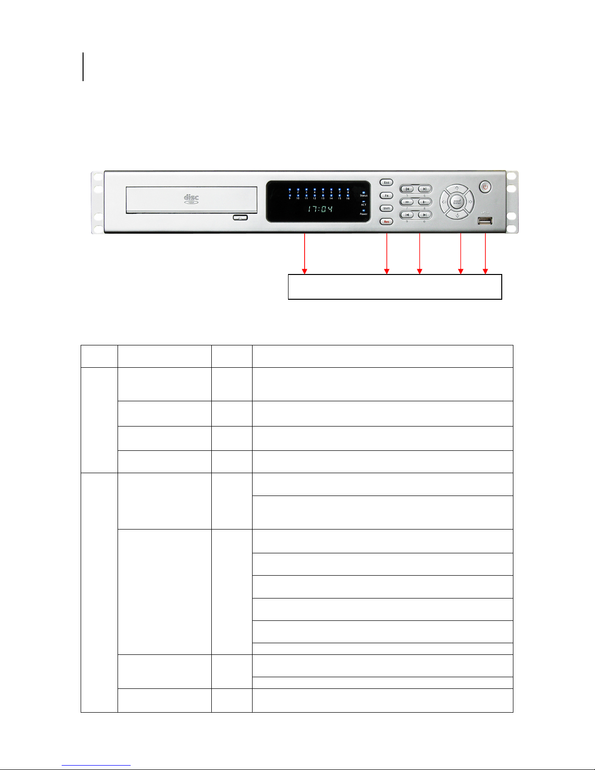
2.1 Front Panel
Front Panel
2.12.1
Front PanelFront Panel
Please refer to Error! Reference source not found. for front panel information.
1 2 3 4 5
SN Button Name
1
2
Channel indication
light
Standby indication
light
Remote control
signal receiver
Power indication
light
Cancel
Assistant
Shift
Record
Figure 2-1
Icon
1-8
9-16
Status
ACT
Power The power indicatio
Esc
Fn
Shift
Rec
Function
When system is recording
become on.
When DVR is standing by, this lamp turns on.
To receive signals from remote control.
up.
Go back to previous menu or cancel current operation in
function menu interface.
In video playback mode, click this button to go back to
real-time monitor mode.
In 1-ch monitor mode: pop up assistant function:PTZ
control and Video color
In motion detection interface, working with direction keys
to finish setup.
Clear: Press Fn for 1.5 seconds to clear all contents in
current text box.
In preview interface (There is no other menu), click this
button for 3 seconds to switch between TV/VGA.
In text box input mode, press this button to switch
between numeral/English character (small/capitalized).
Special combined operation in some menus.
In input mode, switch between numeral/character and
other function keys.
In four-window preview mode, it can work as Fn button.
Enable or disable record function manually. In record
control menu, working with direction keys to select
©2009 IC Realtime, Inc.
Page 15

15
1
rresponding
recording channel.
3
4
5
Play/pause II
Reverse/pause II
Fast play
Slow play
Next I
Previous I
Direction key
O.K Enter
Power button
USB port
► In playback mode: click this button to switch between
>
< >
In playback mode: play or pause video.
In text box: input number 6.
In playback mode: reverse play video.
In text box: input number 5.
In playback mode: click this button to switch between
various fast play speeds and normal playback.
In text box: input number 7.
various slow play speeds and normal playback.
In text box: input number 8.
In playback mode: play the next video.
In text box: input number 0.
In playback mode: play the previous video.
In text box: input number 9.
<
Move cursor
In text box: increase or decrease numerals.
In dropdown list, modify current setup.
In monitor mode, click this button to go to the 1st channel-
or 4th channel. (Single-channel monitor mode).
In text box input mode, press SHIFT and then use
up/down key to input number 1 or 4.
In the main menu or sub-menu interface, click left or right
key to move cursor.
In playback mode: Click left/right key to select co
option in the function menu.
In monitor mode, click left/right key to go to 2nd channel
or 3rd channel (single-window monitor mode)
In text box input mode, press SHIFT and then use
left/right key to input number 2 or 3.
Confirm
Go to the main menu
Boot up or shut down the DVR
Connect to USB port
2.2
2.2 Rea
Rearrrr Panel
ReaRea
Panel
Panel Panel
2.22.2
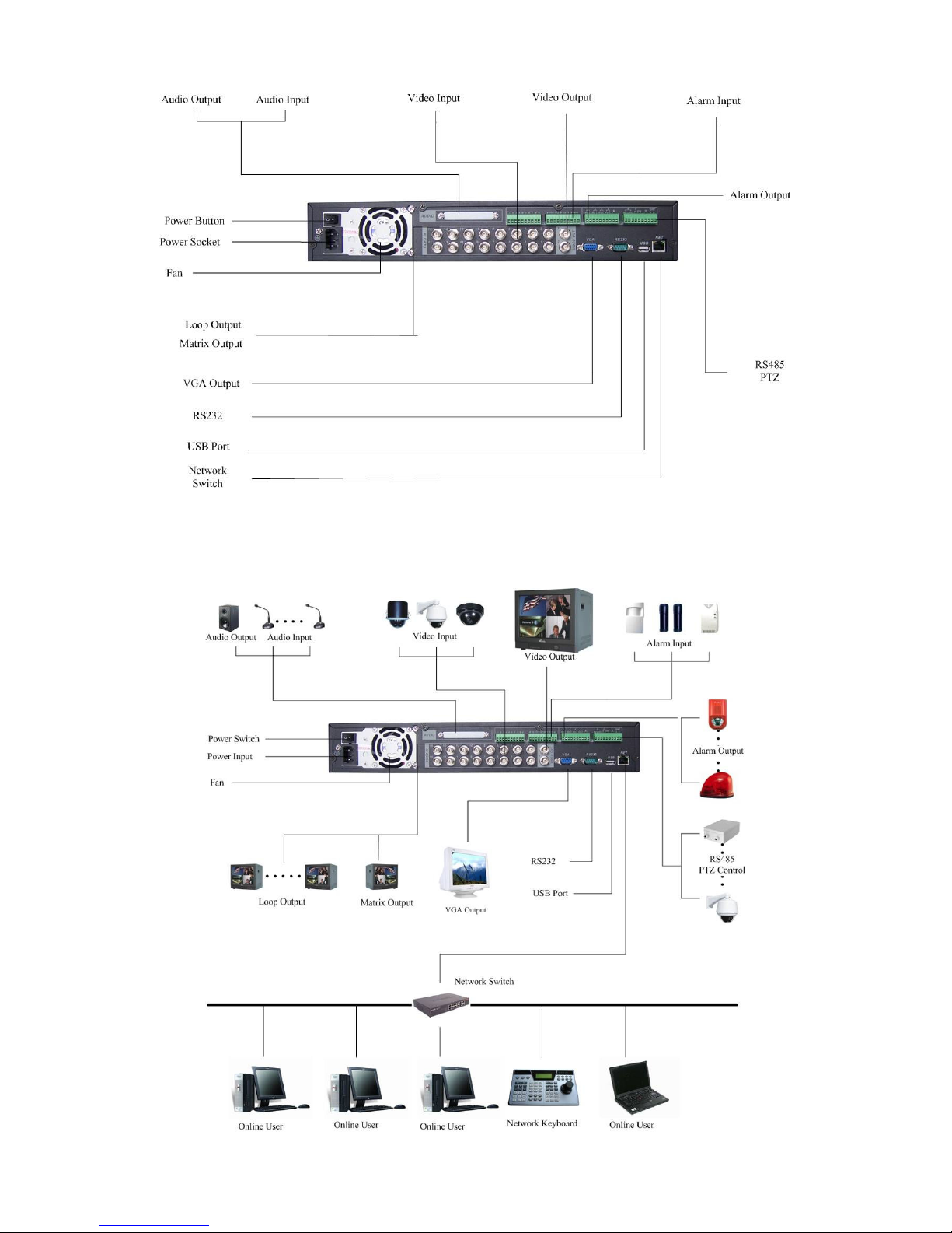
2.2.1 Overview
Please refer to Figure 2-2 for real panel information.
©2009 IC Realtime, Inc.
Page 16
16
Figure 2-2
2.2.2 Connection Sample
Here is a connection sample for your reference. See Figure 2-3.
©2009 IC Realtime, Inc.
Page 17
17
Figure 2-3
2.3
2.3 Remote Control
Remote Control
2.32.3
Remote ControlRemote Control
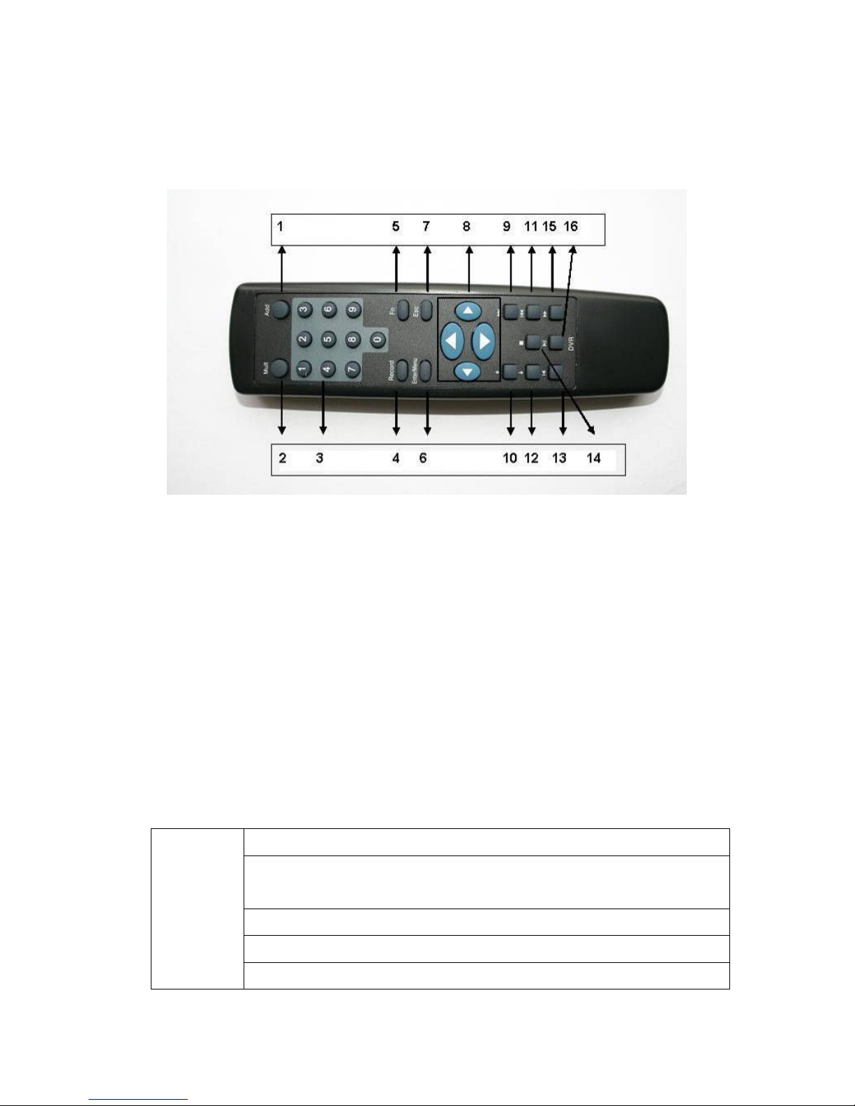
The remote control interface is shown as in Figure 2-4.
Figure 2-4
Serial Number Function
1 remote switch
2 Multiple-window switch
3 0-9 number key
4 Record
5 Auxiliary key
6 Confirm /menu key
7 Cancel
8 Direction key
9 forward
10 Previous
11 Back
12 Next
13 Slow play
14 Stop
15 Fast play
16 Play/Pause
2.4
2.4 Mouse Control
Mouse Control
2.42.4
Mouse ControlMouse Control
Left click
mouse
In real-time monitor mode, you can go to the main menu.
When you have selected a menu item, left click the mouse to view the
content within that menu.
Execute the control operation.
Modify checkbox or motion detection status.
Expand drop-down menus
©2009 IC Realtime, Inc.
Page 18
18
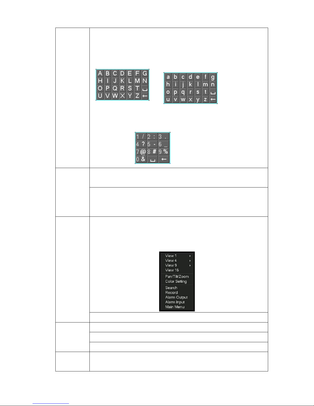
In the input box, you can select different input methods. By left clicking the
corresponding button on the panel you can input upper and lower case
letters, numbers and symbols. Also note, the _ represents a space, and ←
works as a backspace or delete.
Double left
click mouse
Right click
mouse
To input symbols, you can use the corresponding numeral in the front panel.
For example, click number 1 to input “/” , or you can click the number in the
on-screen keyboard directly.
Implement special control operation such as double click one item in the file
list to playback the video.
In multiple-window mode, double left click one channel to view in full-window.
Double left click current video again to go back to previous multiple-window
mode.
In real-time monitor mode, pops up shortcut menu: one-window, four-window,
nine-window and sixteen-window, Pan/Tilt/Zoom, color setting, search,
record, alarm input, alarm output, main menu.
Among which, Pan/Tilt/Zoom and color setting for the currently selected
channel. Also, if you are in the multiple-window access mode, the system
automatically switches to the corresponding channel.
Exit current menu without saving any changes. Back out of current menu.
Scroll wheel
Move
mouse
In numeral input box: Increase or decrease numeral value.
Switch the items in the check box.
Page up or page down
Control the mouse cursor
©2009 IC Realtime, Inc.
Page 19

19
Select motion detection zone Click & Drag
mouse
2.5
2.5 Virtual Keyboard & Front Panel
Virtual Keyboard & Front Panel
2.52.5
Virtual Keyboard & Front PanelVirtual Keyboard & Front Panel
2.5.1 Virtual Keyboard
The system supports Alphanumeric (upper and lower case) and symbols input.
Move the cursor to the text column and you will see the input button pops up on the
right. Click that button to switch between numbers and letters. Use > or < to shift
between small characters and capitalized characters.
2.5.2 Front Panel
Move the cursor to the text column. Click Fn key and use direction keys to select
number you wanted. Please click enter button to input.
Select privacy mask zone
©2009 IC Realtime, Inc.
Page 20
20
3333 Installation and Connections
Installation and Connections
Installation and ConnectionsInstallation and Connections
Note: All the installation and operation should conform to your local electric
safety rules.
3.1
3.1 Check Unpacked DVR
Check Unpacked DVR
3.13.1
Check Unpacked DVRCheck Unpacked DVR
Upon receipt of the DVR from the courier, please check whether there is any visible
damage to the DVR appearance. The protective materials used for the package of
the DVR can protect most accidental clashes during transportation. Then you can
open the box to check the accessories.
Please check the items in accordance with the list on the warranty card. Finally you
can remove the protective film of the DVR.
3.2
3.2 HDD Installation
HDD Installation
3.23.2
HDD Installation HDD Installation
3.2.1 Choose HDDs
We recommend Seagate/IBM/Hitachi HDD of 7200rpm or higher.
3.2.2 Calculate HDD Size
You can use 120G-1500G HDD to guarantee higher recording durations.
The formula of total HDD size is:
Total Capacity (MB) = Camera Amount * Recording Hours * HDD Usage Per Hour
(M/h)
H.264 compression is ideal for standalone DVRs. It can save more than 30% HDD
capacity over MPEG4 part 1. When you calculate the total HD capacity, you should
estimate the average HDD capacity per hour for each channel.
For example, for a 4-ch DVR, the average capacity of HDD usage per hour per
channel is 200M/h. If you want the DVR to record video 12 hours each day for 30
days, the total space needed on your HDDs is: 4 channels * 30 days * 12 hours *
200 M/h = 288G which requires one 320G HDD or 2 160G HDDs.
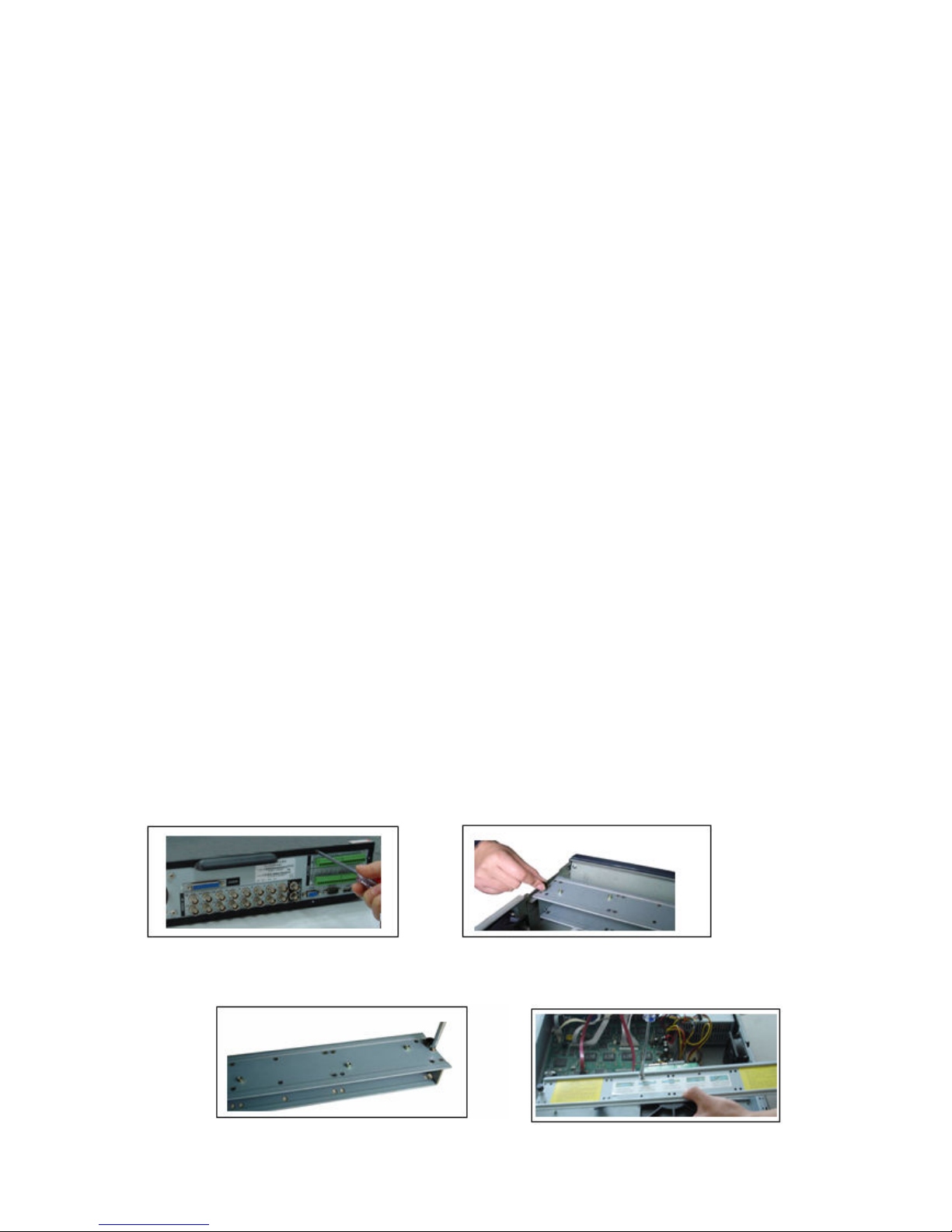
3.2.3 HDD Installation
Data ribbons and fastening screws are provided in the accessory box.
Please follow the instructions below to install hard disk.
1. Loosen the screws of the upper cover. 2. Remove the HDD bracket from internal unit.
2
©2009 IC Realtime, Inc.
Page 21
21
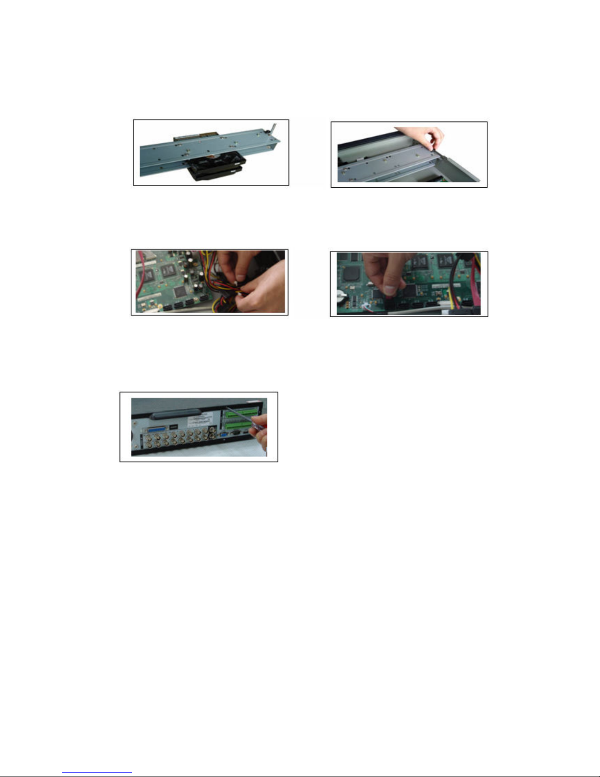
3. Dismantle the upper HDD bracket. 4. Install the HDD. Note the HDD is placed
If the HDD amount is less than four, you do not need to install the HDD bracket.
5.
Screw the two bracket parts together. 6. Put HDD bracket back and then fix firmly.
upside down. make sure bracket is in
correct position.
8
7. Loosen the power cable. 8. Connect to the SATA ports and then connect
power cord to the HDDs.
9. Place the upper cover back and screw firmly .
After HDD installation, check connection of data ribbon and power cord.
3.3
3.3 CD
CD/DVD
3.33.3
For built-in burner, you remove the plastic knockout to install the CD/DVD burner.
This series DVR is compatible with various burner brands popular in today’s market.
You can consult our local technical support or visit our website for more information.
3.4
3.4 DDDDesktop and Rack
3.43.4
/DVD Burner
CDCD
/DVD/DVD
esktop and Rack M
esktop and Rackesktop and Rack
Burner Installation
Burner Burner
Installation
Installation Installation
Mounting
ounting
M M
ountingounting
3.4.1 Desktop Mounting
To prevent surface damage, please make sure that the rubber feet are securely
installed on the four corners of the bottom of the unit.
Position the unit to allow for cable and power cord clearance at the rear of the unit.
Please make sure that the air flow around the unit is not obstructed.
3.4.2 Rack Mounting
The DVR occupies 1.5 rack units (1.5U) of vertical rack space.
©2009 IC Realtime, Inc.
Page 22
22
The hardware necessary to mount the DVR into a rack is supplied with the unit.
Use three (3) screws on each side to fix the unit firmly.
Make sure the installation environment is below 55℃.
Rear doors may be used only on rack columns that are more than 6 inches (15cm)
deep.
Install the cabinet in ventilated place. Avoid extreme heat, humid or dusty conditions.
You can use a soft dry brush to clean opening outlet, cooling fan and etc regularly.
3.5
3.5 Connecting
Connecting Power
3.53.5
Connecting Connecting
Please check the input voltage and device power button is match or not. .
We recommend you use UPS to guarantee steady operation, DVR life span, and
other peripheral equipments operation such as cameras.
3.6
3.6 CCCConnecting
3.63.6
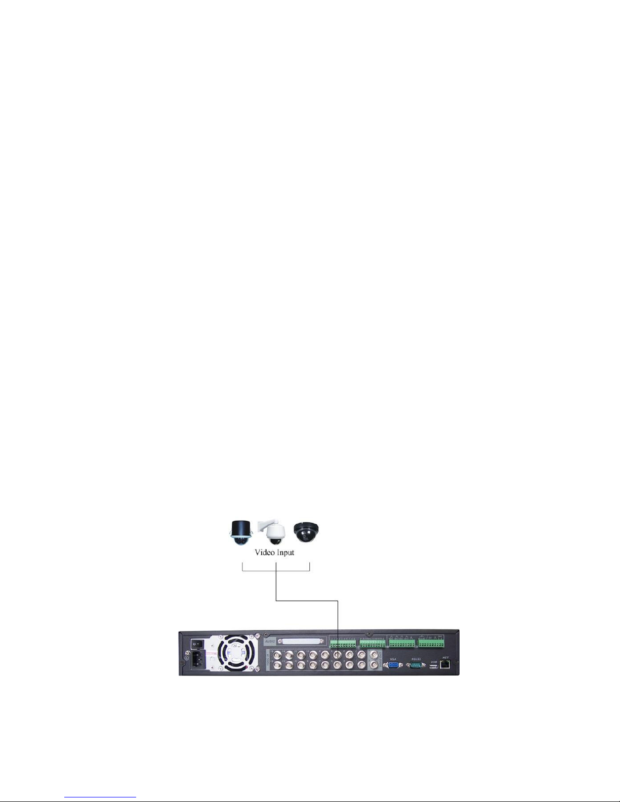
3.6.1 Connecting Video Input
The DVR automatically detects the video standard (PAL or NTSC) whenever you
connect a video input. It accepts both color and black-and-white video.
NOTE:
Enabling line lock on cameras may cause video distortion. There may be noise in
If a video distribution amplifier is installed between the video source and the DVR,
To connect each video input:
1. Connect a coaxial cable to the camera or other analog video source.
2. Connect the coaxial cable to the video in connector on the rear panel.
Please refer to Figure 3-1 for more information.
NOTE:
You need to use a BNC installation tool to connect coaxial cables to the rear panel.
onnecting V
onnectingonnecting
the camera’s power source. If video from one or more cameras is distorted, we
recommend you disable the line lock on the camera.
do not set the output video level above 1 Vp-p.
Power Supply
Power Power
Video
V V
Supply
SupplySupply
ideo IIIInput
ideoideo
nput and
nputnput
and O
andand
Output
utput D
O O
utpututput
Devices
evices
D D
evicesevices
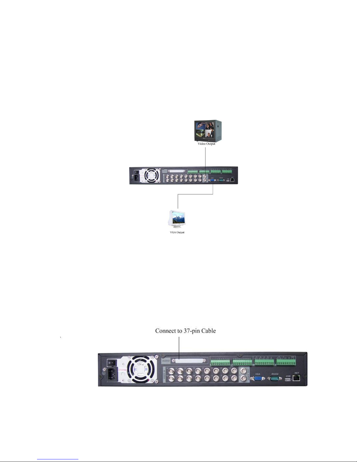
3.6.2 Connecting Video Output
Figure 3-1
©2009 IC Realtime, Inc.
Page 23
23
This section provides information about physically connecting video display devices
to the DVR. See Figure 3-2.
If you connect the DVR with a TV monitor or VGA monitor, the DVR can automatically
detect the monitor type. Without any output device, by default, the DVR is configured
to use a TV monitor. If your application requires a VGA monitor, you have to press
“FN2” or Shift on the front panel.
NOTE:
Video output 1 and VGA can’t display at the same time. But Video output 2 can
display properly with Video Output 1 or VGA.
Figure 3-2
3.7
3.7 CCCConnecting
3.73.7
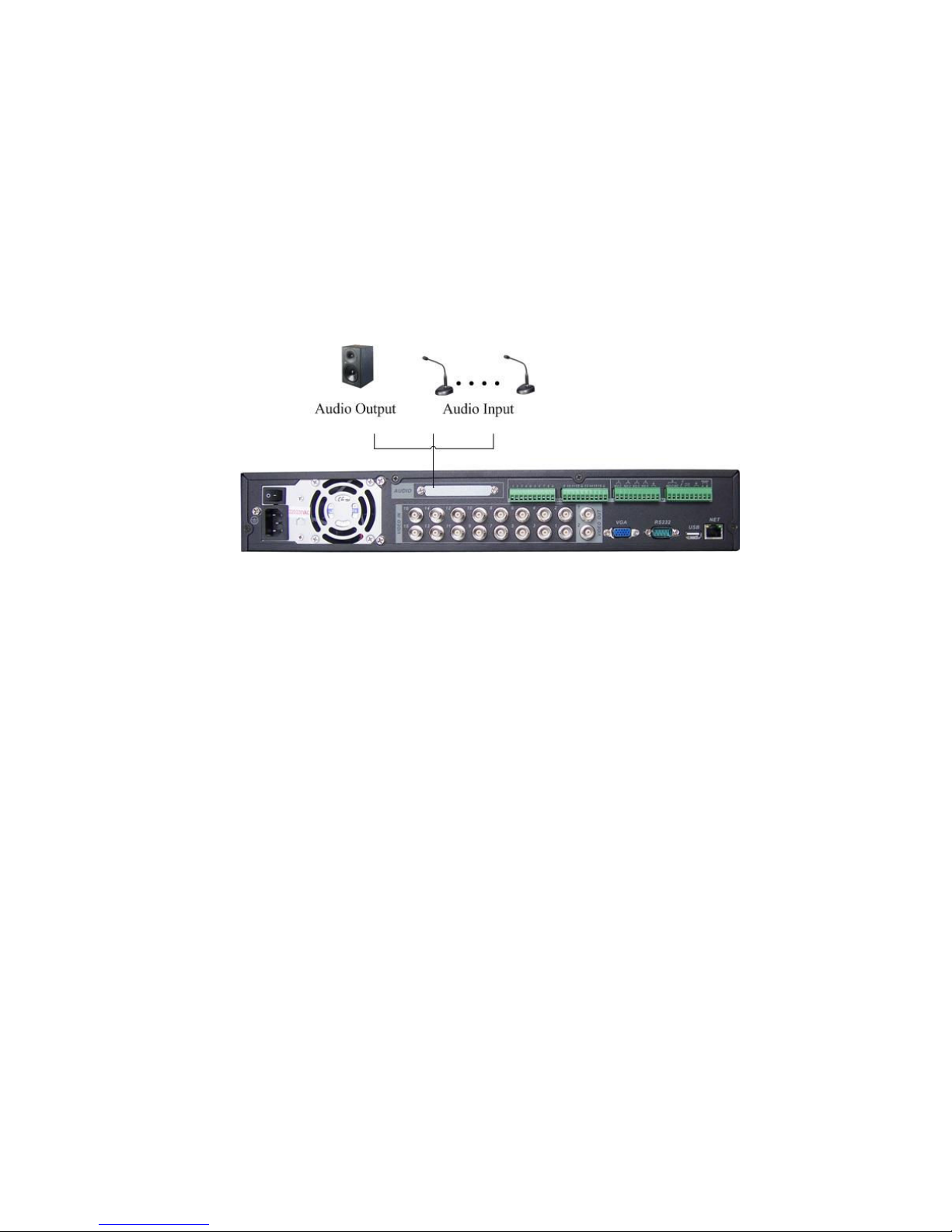
For the 25-pin or 37-pin interface, different models include different functions.
For example, our 16-ch audio/video basic model has 16 audio inputs, 1 audio output,
1 bidirectional audio input. See Figure 3-3.
onnecting Audio Input
onnectingonnecting
Video, Matrix
Video, Matrix
Video, MatrixVideo, Matrix
Audio Input &
Audio Input Audio Input
& Output
Output, Bidirectional Audio, Looping
& &
OutputOutput
Figure 3-3
, Bidirectional Audio, Looping
, Bidirectional Audio, Looping , Bidirectional Audio, Looping
3.7.1 Audio Input/Audio Output
©2009 IC Realtime, Inc.
Page 24
24
Our 16-ch loop matrix and audio/video model has 16 looping video inputs, 1
matrix video outputs, 4 audio inputs, 1 bidirectional audio input, 1 audio output.
The DVR encodes audio and video signals simultaneously, which lets you control
audio at the monitored location.
To set up audio:
1. Make sure your audio input device matches the RCA input level. If the device and
RCA input levels do not match, audio distortion problems may occur.
2. Make sure the audio connector is wired as follows:
3. Connect a line input device or pre-amplified microphone to the audio connector for
the video channel on the rear panel.
Please refer to Figure 3-4.
Figure 3-4
Note: some series do not support audio input/output.
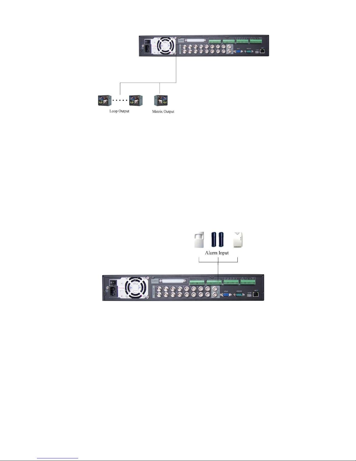
3.7.2 Looping video
The DVR supports looping video. It passes the video input to a monitor or other
analog video device.
To use looping video:
1. Connect a coaxial cable to the video out connector on 37-pin interface.
You need to use a BNC installation tool to connect coaxial cables to the rear panel.
2. Connect the other end of the coaxial cable to the analog device.
3.7.3 Matrix Video Output
Use video matrix output connector during installation to display video sequentially
from each video input. The unit displays each channel for selected seconds. You can
use this feature to verify camera installation.
To display video from each connected video source:
1. Connect a video monitor to the video matrix output connector.
2. Turn the DVR on, the monitor, and each video matrix output source.
3. Verify the video from each source and troubleshoot as necessary.
Please refer to Figure 3-5.
©2009 IC Realtime, Inc.
Page 25
25
Figure 3-5
3.7.4 Alarm Input and Relay Output
The DVR offers 16 alarm inputs for external signaling devices, such as door contacts
or motion detectors. Each alarm input can normally open or normally close. Once
configured, an alarm input can invoke many different activities, including triggering a
relay device, sending an alert to a security office or store pre-alarm video to the DVR.
3.7.5 Alarm Input
For this series DVR, a grounding signal is needed for alarm input.
If you need to connect two units or one DVR and other device, use a relay to
separate them. Please refer to Figure 3-6 for more information.
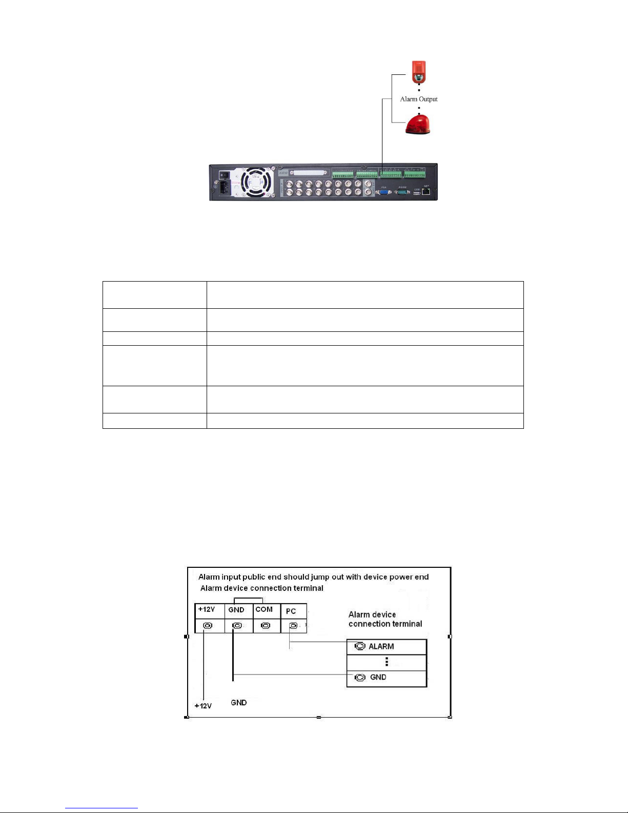
3.7.6 Alarm Output
Do not connect alarm output ports directly with high power loads (no more than 1 A).
You can use the co-contactor to realize the connection between the alarm output port
and the load. Refer to Figure 3-7 for more information.
Figure 3-6
©2009 IC Realtime, Inc.
Page 26
26
Figure 3-7
3.7.7 Alarm Input and Output Details
You can refer to the following sheet and Figure 3-8 for alarm input and output
information.
Parameter
Grounding Alarm
Ground Ground line
Alarm Input
1, 2, …, 16
Relay Output 1,2,3,4: NO and C(Normally Open and Com)
5: NO,C and NC(Normally Open, Com, Normally Closed)
6: Ctrl 12V(This is used for reset the senor)
485 A、B
485 communication port. They are used to control devices
such as PTZ. A is RS-485 Positive & B is RS-485 negative
+12(C)
This should input an external power input.
4/8/16-ch grounding alarm inputs. (Normal open or Normal close type)
Parallel connect COM end and GND end of the alarm detector (Provide external
power to the alarm detector).
Parallel connect the Ground of the DVR and the ground of the alarm detector.
Connect the NC port of the alarm sensor to the DVR alarm input(ALARM)
If you need to reset the touched-off alarm remotely, you can use DVR to supply
controllable 12 V power to the alarm detector such as the smoke detector.
Use the same ground with that of DVR if you use external power to the alarm
device.
Figure 3-8
©2009 IC Realtime, Inc.
Page 27
27
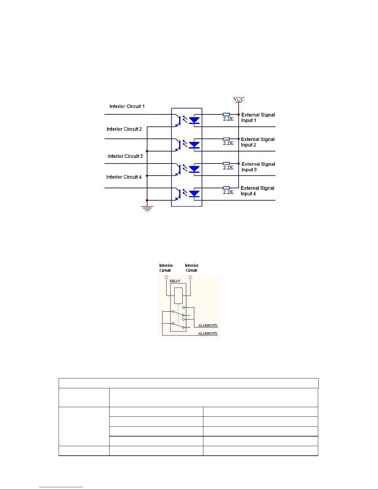
3.7.8 Relay Output Description
6 ways relay alarm output. Provide external power to external alarm device.
To avoid over loading, read the following relay parameters sheet carefully. (See
below table)
The controllable +12v can be used to restore the smoke detector.
Please refer to Figure 3-9 for alarm input module information.
Figure 3-9
Please refer to Figure 3-10 for alarm output module information.
Figure 3-10
Relay Specification
Model:
Material of
JRC-27F
Silver
the touch
Rating
(resistance
load)
Rated switch capacity 30VDC 2A, 125VAC 1A
Maximum switch power 125VA 160W
Maximum switch voltage 250VAC, 220VDC
Maximum switch currency 1A
Insulation
between touches with 1000VAC 1minute 50/60Hz
©2009 IC Realtime, Inc.
Page 28

28
same polarity
between touches with
different polarity
between touch and winding 1000VAC 1minute 50/60Hz
Surge
voltage
Length of
open time
Length of
close time
Longevity
Temperature
3.8
3.8 RS232
RS232
3.83.8
RS232RS232
You can connect the DVR with POS (point of sale systems) or Keyboard through the
RS232.
With POS systems, the DVR can communicate through RS232 and network. For the
POS system, the DVR can integrate the text content and even search the record
through the info. The series DVR also support network keyboard operation. You can
operate the DVR from the keyboard controls instead of using the control pad on the
front panel of the unit.
To connect a NETWORK KEYBOARD to the DVR:
1. Assemble the keyboard according to the instructions in its accompanying
installation manual.
2. Connect the keyboard into one of the RS232 ports on the DVR or through network.
between touches with
same polarity
3ms max
3ms max
Mechanical
Electrical
-40°C ~+70°C (-40°F ~ +158°F)
1000VAC 1minute 50/60Hz
1500V (10×160us)
50×106 times (3Hz)
200×103 times (0.5Hz)
3.9
3.9 RS485
RS485
3.93.9
RS485RS485
When the DVR receives a camera control command, it transmits that command up
the UTP cable to the PTZ device. RS485 is a single-direction protocol; the PTZ
device can’t return any data to the unit. To enable the operation, connect the PTZ
device to the RS485(A,B) input on the DVR. Since RS485 is disabled by default for
each camera, you must enable the PTZ settings first. This series DVR support
multiple protocols such as Pelco-D, Pelco-P.
To connect PTZ devices to the DVR:
1. Connect RS485 A,B on the DVR rear panel. A is RS-485 Positive & B is RS-485
negative
2. Connect the other end of the cable to the proper pins in the connector on the
camera.
3. Follow the instructions for configuring a camera to enable each PTZ device on the
DVR.
3.10
3.10 Other Interfaces
3.103.10
There are still other interfaces on the DVR, such as USB ports. You can refer to
the Figure 3-11 for more information.
Other Interfaces
Other InterfacesOther Interfaces
©2009 IC Realtime, Inc.
Page 29

29
Figure 3-11
©2009 IC Realtime, Inc.
Page 30

30
4444 Overview of Navigation and Controls
Overview of Navigation and Controls
Overview of Navigation and Controls Overview of Navigation and Controls
Before operation, please make sure you have properly installed HDDs and all the
cable connections.
4.1
4.1 Login, Logout & Main Menu
Login, Logout & Main Menu
4.14.1
Login, Logout & Main Menu Login, Logout & Main Menu
4.1.1 Login
When the system boots up, the default video display is a multiple-window view.
Click Enter or left click mouse, you can see the login interface. See Figure 4-1.
There are 4 default accounts you can use.
Username: admin Password: admin (administrator, local and remote)
Username: guest Password: guest (low authority user, local and remote)
Username: user Passwords: user (low authority user who can monitor live feed,
playbacks, and backups)
Username: default Password: default (hidden user – view cameras only)
For your system security, please modify password after your first login.
You can input your password by using the front panel keys, the remote control or a
Figure 4-1
USB mouse which is recommended. Click to switch between numbers,
letters, and symbols.
Note: Three unsuccessful login attempts within 30 minutes will result in system
alarm. Five unsuccessful login attempts will result in an account lock.
4.1.2 Main Menu
After you logged in, the system main menu is shown as below. See
Figure 4-2. There are total six icons: search, information, setting, backup,
advanced and shutdown.
You can move the cursor to highlight the icon, and then left click mouse to enter
the sub-menu.
©2009 IC Realtime, Inc.
Page 31

31
4.1.3 Logout
There are two ways for you to shut down. One is from menu option:
In the main menu click shutdown, you can see an interface is shown as below.
See Figure 4-3.
Figure 4-2
Figure 4-3
There are several options for you. See Figure 4-4.
Figure 4-4
The other ways is to press power button on the front panel for at least 3 seconds,
system will stop all operations. Then you can click the power button in the rear
panel to turn off the DVR.
4.1.4 Auto Resume after Power Failure
The system can automatically backup video and resume previous working status
after power failure.
4.1.5 Replace CMOS Battery
Please make sure to use battery model CR-2032. We recommend your replace
it regularly (such as once every 2-3 years) to guarantee system time accuracy.
4.2
4.2 Record
4.24.2
4.2.1 Live Viewing
Recording O
RecordRecord
ing Operation
ing Oing O
peration
peration peration
©2009 IC Realtime, Inc.
Page 32

32
After you logged in, the system is in a live viewing mode. You can see system
date, time and channel name. If you want to change the system date and time,
you can refer to general settings (Main Menu->Setting->General). If you want to
modify the channel name, please refer to the display settings (Main Menu>Setting->Display)
1111
2222
Recording status 3333
Motion detection
4444
Video loss
Camera lock
Note: Please refer to the following sheet for channel status. stands for
enabled tour function, stands for a disabled tour.
4.2.2 Manual record
Note:
You need to have proper rights to perform the following operations.
4.2.2.1 Manual record menu
There are two ways for you to go to the manual record menu.
Right click mouse or go to the Main Menu -> Advanced->Manual Record.
In live viewing mode you can press the record button on the front panel. You can
also press record on the remote control.
4.2.2.2 Basic operation
There are three statuses: schedule/manual/stop. Highlight icon “○” to select
corresponding channel.
Manual: the highest priority. After manual setup, all selected channels will begin
continuous recording.
Schedule: channel records as you defined in the recording setup (Main Menu-
>Setting->Schedule)
Stop: all channels stop recording.
Note: Manual operation has the highest priority.
4.2.2.3 Enable/disable record
Please check current channel status: “○” means it is not in recording status,
“●” means it is in recording status.
Use either the mouse or the directional keys to highlight a channel number.
Figure 4-5
©2009 IC Realtime, Inc.
Page 33

33
Figure 4-6
4.2.2.4 Enable all channel recording
Highlight ○ below All, to enable recording on all channels.
All channel schedule record
Highlight “ALL” after “Schedule”. See Figure 4-7.
When the system is in schedule recording, all channels will records as you have
previously defined in the schedule interface. (Main menu->Setting->Schedule).
The corresponding recording LED on the front panel will turn on.
Figure 4-7
All channel manual record
Highlight “ALL” after “Manual.” See Figure 4-8.
When the system is in manual recording, all scheduled recordings previously
defined will be ignored. You will see the recording LED light on the front panel
turn on, and the system will begin manual recording.
Figure 4-8
4.2.2.5 Stop all channel recording
Highlight “ALL” after “Stop”. See Figure 4-9.
The system will stop recording no matter what mode is set in the schedule menu
(Main menu->Setting->Schedule)
©2009 IC Realtime, Inc.
Page 34

34
4.3
4.3 Search
4.34.3
4.3.1 Search Menu
There are two ways for you to go to search menu.
Click Pause/Play, in the remote control.
Click search in the main menu.
The search screen is shown below
Search & Playback
Search Search
& Playback
& Playback& Playback
Figure 4-9
©2009 IC Realtime, Inc.
Page 35

35
Figure 4-10.
Usually there are three file types:
R: regular recording file.
A: external alarm recording file.
M: motion detection recording file
There are several playback windows. The DVR support 1/2-ch playback
©2009 IC Realtime, Inc.
Page 36

36
Figure 4-10
Please refer to the following sheet for more information.
Serial Number Function
1 Play
2 Backward
3 Stop
4 Slow play
5 Fast play
6 Previous frame
7 Next frame
8 Volume
9 Previous file
10 Next channel
11 Next file
12 Previous channel
13 Search
14 Backup
This series DVR supports 2-channel simultaneous playback.
4.3.2 Basic Operation
4.3.2.1 Playback
There are various search parameters: video type, channel number or time. The
system can max display 128 files in one screen. You can use page up/down, to
view if there are more than one page.
You can double click file name to view the file content.
4.3.2.2 Accurate playback
Input time (h/m/s) in the time column and then click the search button. Your
results will appear at the top.
4.3.2.3 Synchronized playback function when playback
During a playback, you can click a number key. The system can switch to the
corresponding channel video of the same time.
4.3.2.4 Digital zoom
When the system is in full-screen playback mode you can drag your mouse in the
screen to select a section and then left click and drag to digitally zoom in. You
can right click to return to your previous view.
4.3.2.5 File backup
You can backup directly from the search menu. You can draw a √ before the file
name (multiple choices) and click backup to start the backup process. (Button 14
in
©2009 IC Realtime, Inc.
Page 37

37
Figure 4-10).
4.3.2.6 Slow playback and fast playback
Refer to the following sheet for slow play and fast playback function.
Button Illustration Remarks
Fast play ,
In playback mode, click this , to
switch between various fast play
modes such as fast play 1,fast play
2 and more.(Fast play 1 means fast
Frame rate may
vary due to
different DVR
versions.
play level 1 or not about speed)
Slow play , ► (Or
you can turn the
outer ring counter
clockwise.)
3、Play/Pause►
4、Previous/next
In playback mode, click this , to
switch between various slow play
modes such as slow play 1 or slow
play 2.
In slow playback mode, click this , to
switch between play/pause modes.
In playback mode, you can click
and to view previous or next
video in current channel.
4.3.2.7 Fast forward/fast backward and frame by frame playback
Special Functions
of Shuttle and Jog
Fast forward(outer
ring clockwise)
Fast backward(outer
ring counter
clockwise)
Illustration
In playback mode, turn the shuttle
(outer ring) clockwise one round to
view in fast level 1. Turn it two
rounds to get fast level 2. You can
continue turning it to get different
speeds.
In playback mode, turn the shuttle
(outer ring) counter clock-wise one
round to play backwards level 1.
Remarks
In forward or
backward mode,
double click
Pause/Play, to get
normal playback.
Frame rate may
vary due to
different version.
Turn it two rounds to get
backwards level 2. You can
continue turning to get different
speeds.
Manual playback
frame by frame
In playback mode, click
play/pause ,, slowly turn the jog
(inner dial) clock-wise to view
frame by frame, counter clock wise
to view 1 frame playback.
4.3.2.8 Backward playback and frame by frame playback
Button Illustration Remarks
Backward play
in playback
interface.
In normal playback mode, left click
backward play, system begins backward
playback.
Double click backward play; again,
system goes to pause mode.
When system is in
backward play or
frame by frame
playback mode,
you can click
play , to go to
©2009 IC Realtime, Inc.
Page 38

38
Manual
playback frame
by frame.
Click pause n normal playback mode,
slowly turn the jog (inner dial) clock-wise
to view frame by frame, counter clock
normal playback.
wise to view single frame playback.
Note:
All the operations here (such as playback speed, channel, time and progress)
have relationship with hardware version.
Some series DVRs do not support some functions or playback speeds.
4.3.3 Calendar
Click the calendar icon in
©2009 IC Realtime, Inc.
Page 39

39
Figure 4-10. System pops up a calendar for your quick reference. Highlighted
dates mean that there are recorded clips. You can click blue date to view file list.
In Figure 4-11 you can see there are video files in May 13th and 14th. Double
click the date to view file list.
4.4
4.4 Record Setup (Schedule)
Record Setup (Schedule)
4.44.4
Record Setup (Schedule)Record Setup (Schedule)
When the system boots up, it is in default 24-hour regular mode. You can set
record type and time in the schedule interface.
4.4.1 Schedule Menu
In the main menu, from setting to schedule, you can go to schedule menu. See
Figure 4-12.
There are three recording types: R-Regular, MD-Motion detection, A- Alarm.
Figure 4-11
4.4.2 Basic Operation
There are a total six periods. See Figure 4-12.
Channel: Select the channel number first. You can select “all” if you want to set
recording for all of your channels.
Week day: There are eight options: ranges from Saturday to Sunday and all.
Redundancy: This enables the redundancy function. You can highlight
Redundancy, to activate this function. Note, before enabling this function, set at
least one HDD as redundant.(Main menu->Advanced->HDD Management)
Record types: There are three types: regular, motion detection (MD) and Alarm.
©2009 IC Realtime, Inc.
Figure 4-12
Page 40

40
Please highlight icon to select the corresponding function.
At the bottom of the menu, there are color bars for your reference. Green stands
for regular recording, yellow stands for motion detection and red stands for alarm
recording.
After completing all the setups please click save button.
4.4.1.1 Quick Setup
This function allows you to copy one channel setup to another. After setting in
channel 1, you can click paste button and turn to channel 2 and then click copy.
You can finish setting for one channel and then click save, or you can finish all
setup and then click save, to memorize all the settings.
4.4.1.2 Redundancy
Redundancy function allows you to memorize recorded files to one or several
disks. These files are created, packaged and closed simultaneously. If there is a
drive failure, there will be a spare copy on the other disk. You can use this
function to maintain data reliability and safety.
In the main menu navigate from Setting to Schedule. Highlight the redundancy
button to enable this function. See Figure 4-12.
In the main menu navigate from Advanced to HDD management and you can
assign one or more disk(s) as redundant. You can select from the dropdown list.
See Figure 4-13. System auto overwrites old files once hard disk is full.
Please note that only read/write disks or read-only disks can backup a file and
support file search function, so you need to have at least one read-write disk;
otherwise you can not record video.
Note
About redundancy setup:
If the current channel is not recording, the current setup will be activated when
the channel begins recording the next time.
If the current channel is recording, the current setup will be activated right away.
The current file will be a packet and a form file, then the system will be recording
as you have just defined.
After completing all the setups please click save button, system goes back to the
previous menu.
©2009 IC Realtime, Inc.
Page 41

41
Figure 4-13
Playback or search in the redundant disk.
There are two ways for you to playback or search in the redundant disk.
Set redundant disk(s) as read-only disk or read-write disk (Main menu-
>Advanced->HDD management). See Figure 4-13.This change will require a
reboot. You can now search or playback from the redundant disk.
Dismantle the disk and play it in another PC.
4.5
4.5 Detect
4.54.5
4.5.1 Detect Menu
In the main menu, from Setting to Detect, you can see motion detect interface.
See Figure 4-14. There are three detection types: motion detection,
video loss, camera masking.
4.5.2 Motion Detect
Detection menu is shown as below. See Figure 4-14.
Channel: select the channel you want to configure for motion detection.
Event type: from the dropdown list you can select the detection type.
Record Channel: select the channel to activate recording function once the
Latch: when detection is complete, the auto trigger continues detecting for a
Region: Select region from Figure 4-15 and you can specify a motion detection
Sensitivity: Ranges from 1-6. 1 is the lowest and 6 is the highest level of
Show message: You can choose to pop up a message to alarm you in the local
Send email: System can send out email to alert you when alarm occurs. .
Detect
DetectDetect
detection occurs. Make sure you have set MD record in the schedule menu
(Main Menu->Setting->Schedule
specified time. The value ranges from 10-300 seconds
zone. There are 396(PAL)/330(NTSC) small zones.
sensitivity.
screen.
©2009 IC Realtime, Inc.
Page 42

42
PTZ activation: Here you can set PTZ movement when detection occurs. Such as
go to preset, tour &pattern when there is an alarm. Click “select” you can see an
interface is shown as in Figure 4-16.
Period: Click set button, you can see an interface is shown as in Figure 4-17.Here
you can assign business days or non-business days. In Figure 4-17, click set you
can see an interface is shown as in Figure 4-18.
Anti-dither: Here you can set anti-dither time.
Alarm output: when alarm occurs, the DVR enables peripheral alarm devices.
Tour: Here you can enable the tour function when alarm occurs. It is a one-
window tour.
Highlight icon to select the corresponding function. After configurations are made,
choose “save” to save and the system will go back to the previous menu.
Note: In motion detection mode, you can not use the copy/paste feature to set
channel setup. The recorded video of each channel may not be the same.
In Figure 4-15, you can left click mouse and drag it to set a region for motion
detection. Click Fn to switch between active/passive motion detection. After
completing setup, please press enter to exit or right click to return to the previous
menu
Figure 4-14
©2009 IC Realtime, Inc.
Page 43

43
Figure 4-15
Figure 4-16
Figure 4-17
Figure 4-18
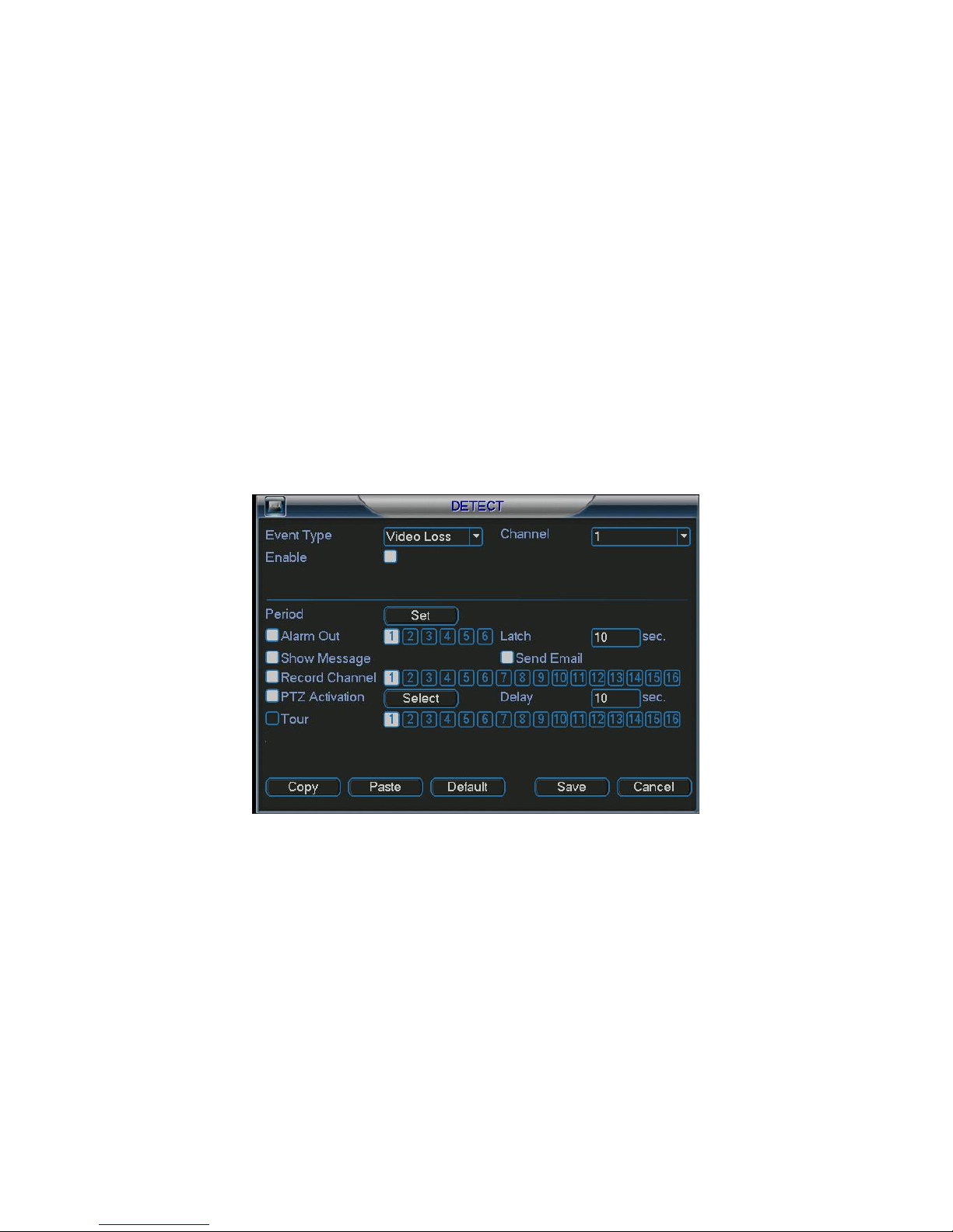
4.5.3 Video Loss
In Figure 4-14, select video loss from the type list. You can see an
interface is shown as in Figure 4-19. This function allows you to be informed
when video loss occurs. You can enable alarm output channel and then enable
show message function also.
Channel: select the channel you want to configure for motion detection.
Event type: from the dropdown list you can select the detection type.
©2009 IC Realtime, Inc.
Page 44
44
Record Channel: select the channel to activate recording function once the
detection occurs. Make sure you have set MD record in the schedule menu
(Main Menu->Setting->Schedule
Latch: when detection is complete, the auto trigger continues detecting for a
specified time. The value ranges from 10-300 seconds
Show message: You can choose to pop up a message to alarm you in the local
screen.
Send email: Enables email alerts when detection occurs.
PTZ activation: Here you can set PTZ movement when detection occurs. Such as
go to preset, tour &pattern when there is an alarm. Click “select” to see the
interface shown in Figure 4-16.
Period: Allows you to set time periods for detection. See Figure 4-17. Here you
can assign business days or non-business days. In Figure 4-17, click set to see
the interface shown in Figure 4-18.
Anti-dither: Here you can set anti-dither time.
Alarm output: when detection occurs, the DVR enables peripheral alarm devices.
Tour: Here you can enable the tour function when detection occurs. It is a one-
window tour. Please go to chapter 5.3.9 Display for tour interval setup.
4.5
.4 Camera Masking
When someone viciously masks the lens, the system can alert you to guarantee
video continuity or trigger external peripherals. Camera masking interface is
shown as in Figure 4-20.
Channel: select the channel you want to configure for motion detection.
Event type: from the dropdown list you can select the detection type.
Record Channel: select the channel to activate recording function once the
detection occurs. Make sure you have set MD record in the schedule menu
(Main Menu->Setting->Schedule
Latch: when detection is complete, the auto trigger continues detecting for a
specified time. The value ranges from 10-300 seconds
Figure 4-19
©2009 IC Realtime, Inc.
Page 45

45
Show message: You can choose to pop up a message to alarm you in the local
screen.
Send email: Enables email alerts when detection occurs.
PTZ activation: Here you can set PTZ movement when detection occurs. Such as
go to preset, tour &pattern when there is an alarm. Click “select” , you can see an
interface is shown as in Figure 4-16.
Period: Allows you to set time periods for detection. See Figure 4-17. Here you
can assign business days or non-business days. In Figure 4-17, click set to see
the interface shown in Figure 4-18.
Anti-dither: Here you can set anti-dither time.
Alarm output: when detection occurs, the DVR enables peripheral alarm devices.
Tour: Here you can enable the tour function when detection occurs. It is a one-
window tour: Go to chapter 5.3.9 Display for tour interval setup.
Note:
In this interface the copy/paste function is only valid for the same event type. For
example, you can not copy a channel setup in video loss mode to camera
masking mode.
Figure 4-20
©2009 IC Realtime, Inc.
Page 46

46
4.6
4.6 AAAAlarm Setup and Alarm Activation
4.64.6
All alarm devices should be properly connected prior to configuring alarm settings.
4.6.1 Alarm Menu
In the main menu, click Setting then Alarm. You can see an interface is shown as
in Figure 4-21.
4.6.2 Alarm setup
Alarm interface is shown as below. See Figure 4-21.
Alarm in: Select channel number.
Event type: There are two types: local input/ network input.
Type: Normal open or normal close.
PTZ activation: Setup PTZ movement when alarm occurs, such as go to a preset,
Period: Click set button you can see an interface is shown as in Figure 4-23. Here
Figure 4-26, click set button, you can see an interface is shown as in Error!
Anti-dither: Here you can set anti-dither time.
Show message: System can provide pop up notifications in the local host screen
Send email: Enable email notifications for alarm occurrences.
Record channel: you can select proper channel to record alarm video (Multiple
Latch: This is where you can set proper delay duration. Value ranges from 10 to
Tour: Here you can enable tour function when alarm occurs. It is a one-window
larm Setup and Alarm Activation
larm Setup and Alarm Activation larm Setup and Alarm Activation
tour or pattern when there is an alarm. Click “select” button, you can see an
interface is shown as in Figure 4-25.
you can set business days and non-business days. In
Reference source not found.. Here you can set your own setup for business day
and non-business day.
if this function is enabled.
choices). At the same time you need to set alarm record in schedule interface
(Main Menu->Setting->Schedule) and select schedule record in manual record
interface (Main Menu->Advance->Manual Record).
300 seconds. System automatically delays specified seconds in turning off alarm
and activated output after external alarm cancelled.
tour: Please go to chapter 5.3.9 Display for tour interval setup.
Please highlight icon to select the corresponding option. After completing all
the setups please click save button, system goes back to the previous menu.
©2009 IC Realtime, Inc.
Page 47

47
Figure 4-21
Figure 4-22
Figure 4-23
Figure 4-24
©2009 IC Realtime, Inc.
Page 48
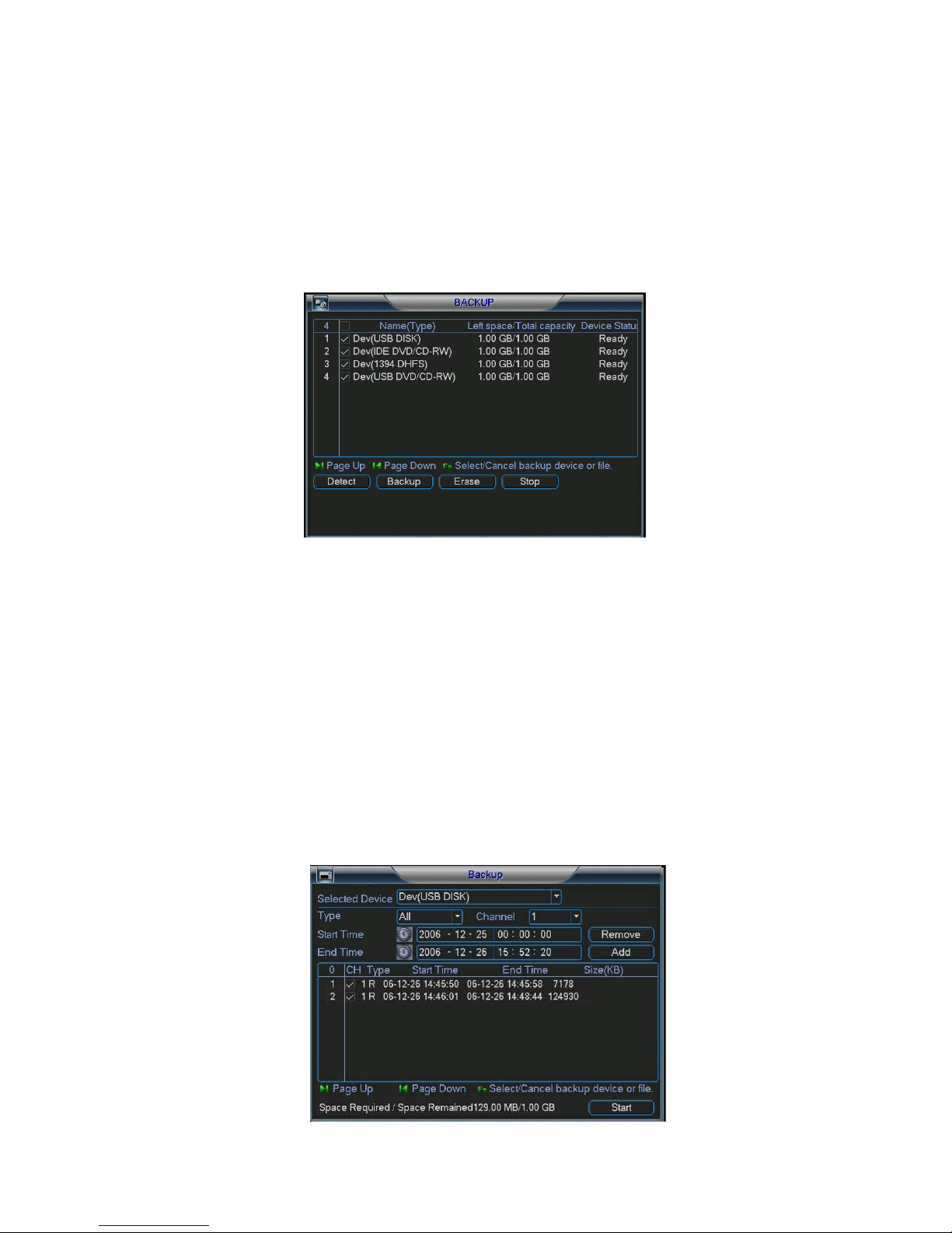
48
4.7
4.7 Backup
Backup
4.74.7
Backup Backup
The DVR supports various backup devices such as CD-RW, DVD drives, USB
backup and network downloads. Here we will introduce a USB backup first. You
can refer to Chapter 7: Web Client Operation for network downloads & backup
operations.
4.7.1 Detect Device
Click backup button, you can see an interface is shown as in Figure 4-25.Here is
for you to view devices information.
Figure 4-25
4.7.1 Backup
Select your desired backup device first, and then specify your channel & time
parameters. Click ‘add’ to start the search. All files matching the search criteria
will populate the list below. The system will automatically calculate the required
and remaining space allotted from the selected device. See
Figure 4-26.
The system only backup files marked with a √ before the channel name. You can
use Fn or cancel to delete √’s after the file serial number.
Click backup button when you’re ready to send files to the selected device. There
is a progress bar for your reference.
After backup completed, you can see a dialogue box prompting successful
backup.
©2009 IC Realtime, Inc.
Page 49
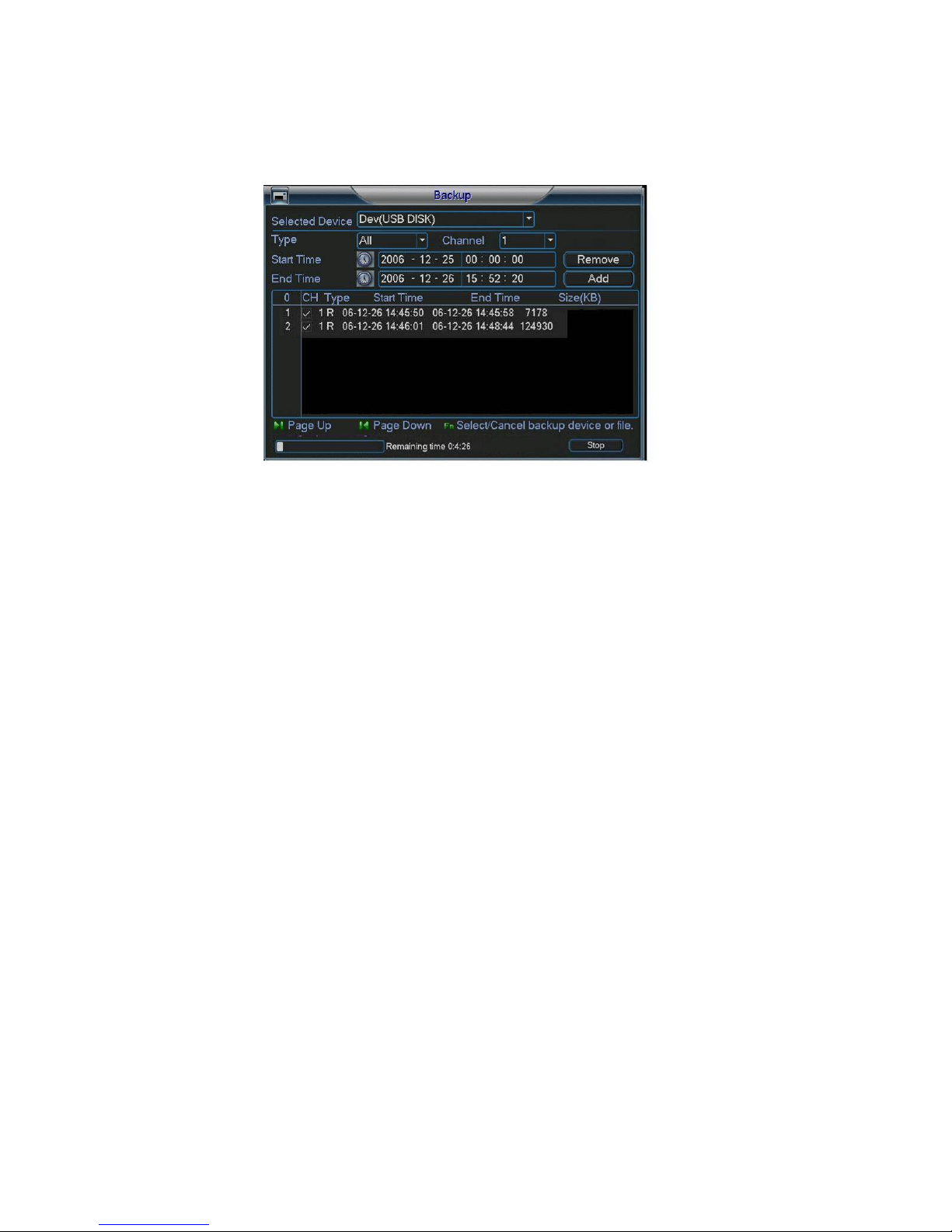
49
Click start button, system begins burning. At the same time, the start button
becomes stop button. You can view the remaining time and process bar at the left
bottom. See Error! Reference source not found..
Figure 4-27
Tips:
During the backup process, you can click ESC to exit the current menu; however,
the system will not terminate the backup process.
Figure 4-26
Note:
When you click stop button during the burning process, there are two conditions
for different devices:
For a CD/DVD burner, the stop function becomes activated immediately and
there will be no data burned.
For a USB device, you will have as much data as processed within the burning
time.
The file name format usually is: SN_CH+channel number+time Y+M+D+H+M+S.
In the file name, the YDM format is the same as you set in general interface.
(Main Menu ->Setting ->General).You can visit our website to view listed CDROM type.
4.8
4.8 PTZ Control and Color Setup
PTZ Control and Color Setup
4.84.8
PTZ Control and Color SetupPTZ Control and Color Setup
Note: All the operations here are based on PELCO D1 protocol.
4.8.1 Cable Connection
Please follow the procedures below to go on cable connection
Connect the dome’s RS485 cable to the DVR’s RS485 port. A is (+)positive. B is
(-) negative
Connect the dome’s video output cable to the DVR’s video input port.
Connect power adapter to the dome.
4.8.2 PTZ Setup
Note: The camera video should be in the current screen. Before setup, please
check the following connections are correct:
©2009 IC Realtime, Inc.
Page 50

50
PTZ and decoder connection is in place. Decoder address setup is right.
Decoder A (B) line connects with DVR A (B) line.
Boot up the DVR, input user name and password.
In the main menu, click setting, and then click Pan/Tilt Control ,. The interface is
shown as in Figure 4-28. Here you can set the following items:
Channel: select the current camera channel.
Protocol: select corresponding PTZ protocol(such as PELCOD)
Address: default address is 1.
Baud rate: select corresponding baud rate. Default value is 9600.
Data bits: select corresponding data bits. Default value is 8.
Stop bits: select corresponding stop bits. Default value is 1.
Parity: there are three options: odd/even/none. Default setup is none.
Figure 4-28
After completing all settings please click save button.
In single window display mode, right click mouse (or “Fn” on the front panel or
press “Fn” on the remote control) to highlight pan/tilt/zoom sub menu. See Figure
4-29.
Figure 4-29
Click Pan/Tilt/Zoom, the interface is shown as below. See Figure 4-30.
©2009 IC Realtime, Inc.
Page 51
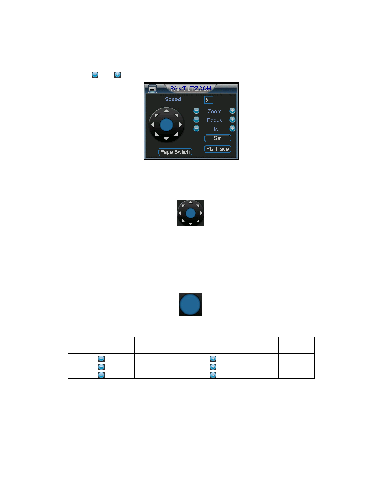
51
Speed: value ranges fro 1 to 8.
Zoom
Focus
Iris
Click icon and to adjust zoom, focus and iris.
In Figure 4-30, click directional arrows (See Figure 4-31) to adjust PTZ position.
There are total 8 directional arrows.
Figure 4-30
Figure 4-31
4.8.3 3D Intelligent Positioning Key
In the middle of the eight directional arrows, there is a 3D intelligent positioning key.
See Figure 4-32.
Click this key and the system goes back to the single screen mode. Drag the mouse
in the screen to adjust section size. It can realize PTZ automatically.
Figure 4-32
Here is a sheet for you reference.
Name Function
Zoom
Focus
Iris
4.9
4.9 Preset
Preset//// PPPPatrol
4.94.9
PresetPreset
key
atrol/P
atrolatrol
function Shortcut
Near ►
Near
close
/Pattern
attern/Scan
/P/P
atternattern
/Scan
/Scan/Scan
key
⊳
Function
key
function Shortcut
Key
►
Far
Far
Open
In Figure 4-30, click the “set” button. The interface is shown as below. See Figure
4-33.
Here you can set the following items:
Preset
Tour (Patrol)
Pattern
©2009 IC Realtime, Inc.
Page 52

52
Border
Figure 4-33
In Figure 4-30, click page switch button, the interface is shown as in Figure 4-34.
Here you can activate the following functions:
Preset
Tour (Patrol)
Pattern
Auto scan
Auto pan
Flip
Reset
Page switch
Figure 4-34
Note: The following setups are usually operated in the Figure 4-30,Figure 4-33 and
Figure 4-34 .
4.9.1Preset Setup
In Figure 4-30, use the eight directional arrows to adjust camera to the proper
position.
In Figure 4-33, click preset button and then input the desired preset number. The
interface is shown as in Figure 4-35.
Now you can add this preset to one tour.
©2009 IC Realtime, Inc.
Page 53

53
Figure 4-35
4.9.2 Activate Preset
In Figure 4-34, input the desired preset number in the No. field and click preset to
activate it.
4.9.3 Patrol setup (Tour Setup)
In Figure 4-33, click patrol. The interface is shown as in Figure 4-36.Input preset
number and add this preset to a patrol (tour). For each patrol (tour), you can input
max 80 presets.
Figure 4-36
4.9.4 Activate Patrol (tour)
In Figure 4-33, input patrol (tour) number in the No. blank and click patrol.
4.9.5 Pattern Setup
In Figure 4-33, click pattern, and then click “begin” to start the pattern’s recording.
The interface is shown as in Figure 4-37. Then you can go to Figure 4-30 to modify
zoom, focus, and iris.
Go back to Figure 4-37 and click “end” when you are finished with recording the
pattern.
Now you can memorize all these operations as pattern 1.
System supports max 255 patterns.
©2009 IC Realtime, Inc.
Page 54

54
4.9.6 Activate Pattern Function
In Figure 4-34, input the desired pattern preset value in the No. field and click pattern
to activate it.
4.9.7 Auto Scan Setup
In Figure 4-33, click border button. You can see an interface is shown as in Figure
4-28.
Go to Figure 4-30. Use the directional arrows to select the camera’s left limit.
Then please go to Figure 4-38 and click left limit.
Repeat the above procedures to set the right limit.
Figure 4-37
Figure 4-38
4.9.8 Activate Auto Scan
In Figure 4-34 click Auto Scan to begin the auto scan. Click stop to end the scan.
Correspondingly, the auto scan button becomes to stop button. Click stop button to
terminate scan operation.
4.10
4.10 Flip
4.104.10
In Figure 4-34, click page switch button, you can see an interface is shown as below.
See
Figure 4-39. Here you can set auxiliary function.
Click page switch button again, system goes back to Figure 4-30.
Flip
FlipFlip
©2009 IC Realtime, Inc.
Page 55

55
Figure 4-39
©2009 IC Realtime, Inc.
Page 56

56
5555 Understanding
Understanding the
Understanding Understanding
5.1
5.1 Menu
Menu TTTTree
5.15.1
Menu Menu
This series DVR menu tree is shown as below.
ree
reeree
the Menu
Menu:::: Operation and Control
thethe
MenuMenu
Operation and Control
Operation and ControlOperation and Control
5.2
5.2 Main
Main MMMMenu
5.25.2
Main Main
After you are logged in, the system main menu is shown as below. See Figure 5-1 .
There are a total six icons: Search, Information, Setting, Backup, Advanced and
Shutdown.
Move the cursor to highlight the icon and then left click mouse to enter its sub-menu.
enu
enu enu
©2009 IC Realtime, Inc.
Page 57

57
5.3
5.3 SSSSetting
5.35.3
In the main menu, highlight the setting icon and left click to select.
The system setting menu is shown as below. See Figure 5-2.
etting
ettingetting
Figure 5-1
5.3.1 General
General setup includes the following items. See Figure 5-3.
System time: Set the date and time of the unit.
Date format: there are three types: YYYY-MM-DD: MM-DD-YYYY or DD-MM-
YYYY.
Date separator: there are three denotations to separate date: dot, line and slash.
DST: Here you can set DST time and date. Enable the DST function and then
click set. You can see an interface is shown as in Figure 5-4. Here you can set
the start time and end time by setting the corresponding week setup. In Figure
5-4, click date button, you can see an interface is shown as in Figure 5-5. Here
you can set the start time and end time by setting the corresponding date setup.
Figure 5-2
©2009 IC Realtime, Inc.
Page 58

58
Time format: there are two types: 24-hour mode or 12-hour mode.
Language: system supports various languages: Chinese (simplified), Chinese
(Traditional), English, Italian, Japanese, French, Spanish (All languages listed
here are optional. Slight difference maybe found in various series.)
HDD full: Here is for you to select working mode when hard disk is full. There are
two options: stop recording or rewrite.
Pack duration: Here is where you specify the recording duration for each
playback file. The default value is 60 minutes.
DVR No: When you are using one remote control to control several DVRs, you
can give a number to each DVR for your management.
Video standard: There are two formats: NTSC and PAL.
Auto logout: Here is for you to set auto logout interval once login user remains
inactive for a specified time. Value ranges from 0 to 60 minutes.
Note:
Since system time is very important, do not modify time unless there is a must!
After completing all the setups please click save button, system goes back to the
previous menu.
Figure 5-3
Figure 5-4
©2009 IC Realtime, Inc.
Page 59

59
Figure 5-5
5.3.2 Encode
The encode menu includes the following items. See Figure 5-6.
*Note: Some series do not support certain features.
Channel: Select the channel you want.
Compression: The system supports H.264. Or you can select from the dropdown
list.
Resolution: The system supports various resolutions, you can select from the
dropdown list. For this model, we can support D1/CIF.
Bit rate: The system supports two types: CBR and VBR. In VBR mode, you can
set video quality.
Quality: There are six levels ranging from 1 to 6. The sixth level has the highest
image quality.
Frame rate: 1-30 frames per second: 1 f/s,2f/s,3f/s, 6f/s,12f/s,25f/s. (Some series
DVRs only support PAL 25f/s )
Video/audio: you can enable or disable the video/audio.
Overlay: click overlay button, you can see an interface is shown in Figure 5-7.
Cover area (Privacy mask): Here is for you to set window blanking section. You
can drag you mouse to set proper section size.
Preview/monitor: privacy mask has two types. Preview means the privacy mask
zone can not be viewed by user when system is in preview status. Monitor means
the privacy mask zone can not be view by the user when system is in monitor
status.
Time display: You can select whether the system displays time or not when you
playback.
Channel display: You can select whether the system displays channel number or
not when you playback.
System default setup is:
Channel:1
Compression:H.264
Resolution: CIF
Bit rate: CBR
Quality: 6
Frame rate: 30f/s
Please highlight icon to select the corresponding function.
©2009 IC Realtime, Inc.
Page 60

60
Figure 5-6
Figure 5-7
5.3.3 Schedule
Please refer to chapter 4.4 schedule.
5.3.4 RS232
The RS232 interface is shown as below. See Figure 5-8
Function: There are various devices for you to select. The console setting is used
to upgrade the device via a serial connection. The keyboard is for you to use a
special keyboard to control the device.
Baud rate: You can select proper baud rate.
Data bit: You can select proper data bit.
Stop bit: There are three values: 1/1.5/2.
Parity: there are three choices: none/odd/even.
After completing all the setups please click save button, system goes back to the
previous menu.
©2009 IC Realtime, Inc.
Page 61

61
Figure 5-8
5.3.5 Network
This is where you can input network information. See Figure 5-9.
IP address: Here you can specify an IP address.
DHCP: Dynamic Host Configuration – The DVR will lease the IP info from any
DHCP server on the network. When the DHCP function is enabled you can not
modify the IP/Subnet mask /Gateway. If you have not enabled DHCP function you
can modify IP/Subnet mask/Gateway. You would need to disable DHCP function
to view current IP information. Besides, when PPPoE is operating, you can not
modify IP/Subnet mask /Gateway.
TCP port: Default value is 37777. (System server port 37778 is reserved for
network UDP use.)
UDP port: Default value is 37778.
HTTP port: Default value is 80.
Max connection: The system supports a maximum of 10 users. 0 means there is
no connection limit.
Transfer mode: Here you can select the priority between fluency/video qualities.
Network download: System can process the downloaded data first if you enable
this function.
After completing all the setups please click save button, system goes back to the
previous menu.
©2009 IC Realtime, Inc.
Page 62
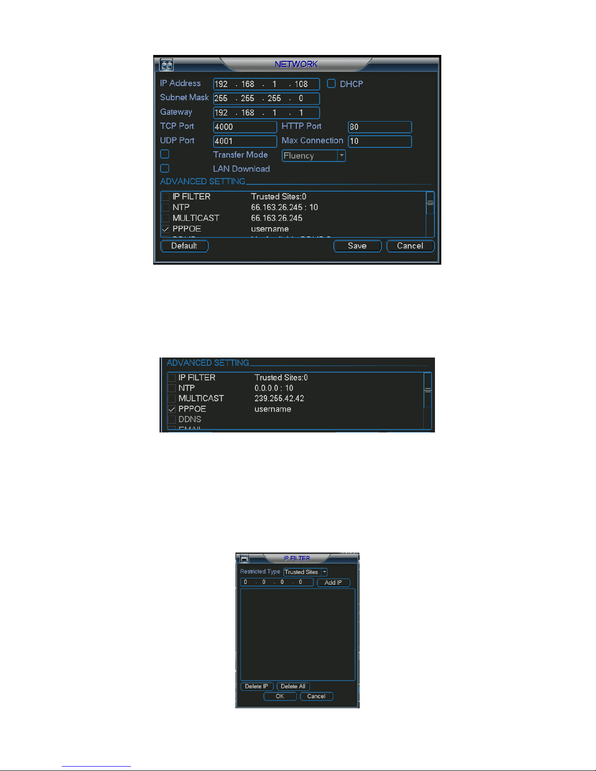
62
Figure 5-9
5.3.5.1 Advanced Setup
The advanced setup interface is shown as in Figure 5-10. Please draw a circle to
enable the corresponding function and then double click the item to go to setup
interface.
Figure 5-10
5.3.5.2 IP Filter
The IP Filter interface is shown as in Figure 5-11. You can specify individual IP
addresses to have access to the DVR. System supports maximum 64 IP addresses.
Please note after you enabled this function, only the IP listed below can access
current DVR.
If you disable this function, all IP addresses can access current DVR.
©2009 IC Realtime, Inc.
Page 63

63
Figure 5-11
5.3.5.3 Multiple Cast Setup
Multiple-cast setup interface is shown as in Figure 5-12.
Figure 5-12
Here you can set a multiple cast group. Please refer to the following sheet for
detailed information.
IP multiple cast group address
-224.0.0.0-239.255.255.255
The higher four-bit of the first byte=”1110”
Reserved local multiple cast group address
-224.0.0.0-224.0.0.255
-TTL=1 When sending out telegraph
-For example
224.0.0.1 All systems in the sub-net
224.0.0.2 All routers in the sub-net
224.0.0.4 DVMRP router
224.0.0.5 OSPF router
224.0.0.13 PIMv2 router
Administrative scoped addressees
-239.0.0.0-239.255.255.255
-Private address space
Like the single broadcast address of RFC1918
Can not be used in Internet transmission
Used for multiple cast broadcast in limited space.
Except the above mentioned addresses of special meaning, you can use other
addresses. For example:
Multiple cast IP: 235.8.8.36
Multiple cast PORT: 3666.
5.3.5.4 PPPoE
The PPPoE menu is shown as in Figure 5-13.
Input “PPPoE name” and “PPPoE password” you get from your ISP (Internet service
provider). Click save then restart the DVR to activate your configuration.
After rebooting, the DVR will connect to the internet automatically. The IP in the
PPPoE is the DVR’s dynamic value. You can then use this IP to access the unit.
©2009 IC Realtime, Inc.
Page 64

64
Figure 5-13
5.3.5.5 NTP Setup
You will need to install an SNTP server (Such as Absolute Time Server) in your PC
first, or, at least have one running on your network.
NTP setup interface is shown as in Figure 5-14.
Host IP: Input your PC address.
Port: This series DVR supports TCP transmission only. Port default value is 123.
Update interval: minimum value is 15(Unit: minute)
Time zone: select your corresponding time zone here.
Here is a sheet for your time zone setup.
City /Region Name Time Zone
London GMT+0
Berlin GMT+1
Cairo GMT+2
Moscow GMT+3
New Deli GMT+5
Bangkok GMT+7
Beijing (Hong Kong) GMT+8
Tokyo GMT+9
Sydney GMT+10
Hawaii GMT-10
Alaska GMT-9
Pacific Time(P.T) GMT-8
American Mountain Time(M.T) GMT-7
American Central Time(C.T) GMT-6
American Eastern Time(E.T) GMT-5
Atlantic Time GMT-4
Brazil GMT-3
Middle Atlantic Time GMT-2
©2009 IC Realtime, Inc.
Page 65

65
Figure 5-14
5.3.5.6 Email Setup
The Email setup menu is shown as in Figure 5-15. Here you can configure email
server information.
Note:
You need to get the email address from your email service provider first.
Please use semicolons to separate multiple servers.
Figure 5-15
5.3.5.7 DDNS Setup
The DDNS setup menu is shown as below. See Figure 5-16.
You need a PC with a static IP address in the network. You will also need the DDNS
software running on this PC. In other words, this PC is a DNS (domain name server).
In the network DDNS menu, input your PPPoE name you get from you ISP and
server IP (PC with DDNS).
Click save button, system prompts for rebooting to get all setups activated.
After rebooting, open IE and input as below:
http://(DDNS server IP)/(virtual directory name)/webtest.htm
e.g.: http://10.6.2.85/DVR _DDNS/webtest.htm.)
Now you can open DDNSServer web search page.
5.3.5.8 Alarm Server
Figure 5-16
©2009 IC Realtime, Inc.
Page 66

66
You can configure the alarm in accordance with different alarm protocols. The
system can inform the alarm server when the alarm occurs. See Figure 5-17.
Figure 5-17
5.3.5.9 FTP
You need to download or buy FTP service tool (such as Ser-U FTP SERVER) to
establish FTP service.
Please install Ser-U FTP SERVER first. From “start” -> “program” -> Serv-U FTP
Server -> Serv-U Administator. Now you can set user password and FTP folder.
Please note you need to grant write right to FTP upload user. See Figure 5-18.
You can use a PC or FTP login tool to test if the setup is right or not.
For example, you can login user with ZHY to FTP://10.10.7.7 and then test if it can
modify or delete the folder or not. See Figure 5-19.
Figure 5-18
©2009 IC Realtime, Inc.
Page 67

67
Figure 5-19
The system also supports the upload of multiple DVRs to one FTP server. You can
create multiple folders under this FTP.
In Figure 5-9, select FTP and then double click mouse. You can see the following
interface. See Figure 5-20.
Figure 5-20
Please highlight the icon in front of Enable to activate the FTP function.
Now the FTP feature can upload alarm video and motion detection video. Note,
when you are using this function, make sure the current upload channel is in motion
detection or alarm record status and there is video available.
Here you can input FTP server address, port and etc.
©2009 IC Realtime, Inc.
Page 68

68
Figure 5-21
File length: upload file length. When the value is larger than the actual file length,
the system will upload the whole file. When this value is smaller than the actual
file length, system will upload until the file length is reached and ignore the
remaining part.
When interval value is 0, the system will upload all corresponding files.
Period 1 and period 2: you can set two periods: one for each channel.
System file name is shown as in Figure 5-22.
Figure 5-22
5.3.6 Alarm
Please refer to Chapter 4.6 Alarm Setup and Activation.
5.3.7 Detect
Please refer to Chapter 4.5 Detect.
5.3.8 Pan/Tilt/Zoom
The pan/tilt/zoom setup includes the following items. Please select channel first.
See Figure 5-23.
Protocol: select corresponding PTZ protocol such as PELCOD.
Address: input corresponding PTZ address.
Baud rate: select baud rate.
Data bit: select data bit.
Stop bit: select stop bit.
Parity: there are three options: none/odd/even.
After completing all the setups please click save button, system goes back to the
previous menu.
For a detailed setup, please refer to Chapter 4.9 preset/patrol/pattern/scan.
©2009 IC Realtime, Inc.
Page 69

69
Figure 5-23
5.3.9 Display
The Display setup menu is shown as below. See Figure 5-24.
Transparency: This is where you can adjust the transparency of the menus. The
value ranges from 128 to 255.
Channel name: This is where you can modify channel names. Please note all of
your modifications here only apply to the DVR locally. You will need to open the
web or client end to refresh channel name.
Time display: You can select to display time or not when the system is in
playback.
Channel display: You can select to channel name or not when the system is in
playback.
Overlay information: System displays some indicator icons on screen for
reference.
Display mode: you can select from the dropdown list: self-adaptive/VGA/TV.
Enable tour: activate tour function.
Interval: Please input proper interval value here.. The value ranges from 5-200
seconds. During the tour process, you can use the mouse or press F2 or Shift to
turn on the tour. Stands for tour enabled, stands for tour disabled.
Motion tour type: System supports either 1/8 view tour.
Alarm tour type: System supports either 1/8 view tour.
Please highlight icon to select the corresponding function.
After completing all the setups please click save button, system goes back to the
previous menu.
©2009 IC Realtime, Inc.
Page 70

70
Figure 5-24
In Figure 5-24, click modify button after channel. You can see an interface is shown
as in Figure 5-25. Please note all your modification here applies to local end only.
You need to refresh web or client-end to get the latest channel name. System max
support 25-digital character.
In tour mode, you can see the following interface. On the right corner, right click
mouse or click shift to control the tour. There are two icons: stands for tour
enabled and stands for tour disabled. See Figure 5-26.
Figure 5-25
©2009 IC Realtime, Inc.
Page 71

71
Figure 5-26
5.3.10 Default
Here you can restore your system to factory default settings. See Figure 5-27.
Select all
General
Encode
Schedule
RS232
Network
Alarm
Detect
Pan/tilt/zoom
Display
Channel name
Please highlight icon to select the corresponding function.
After completing all the setups please click save button, system goes back to the
previous menu.
Warning!
System menu color, language, time display mode, video format, IP address, user
account will not maintain previous setup after default operation!
©2009 IC Realtime, Inc.
Page 72

72
Figure 5-27
5.4
5.4 S
Search
5.45.4
Please refer to chapter 4.3 Search.
earch
S S
earch earch
5.5
5.5 Advanced
Advanced
5.55.5
Advanced Advanced
Left click advanced icon in the main window, you can see an interface is shown as in
Figure 5-28. There are total seven submenus: HDD management, alarm output,
abnormity, manual record, account, auto maintain, and TV adjust.
Figure 5-28
5.5.1 HDD Management
Here you can view and manage hard disks. See Figure 5-29.
You can assign functions for each hard disk from the dropdown menu.
When you use the redundant backup function, you can set one or more redundant
HDD(s).
©2009 IC Realtime, Inc.
Page 73

73
Please note, you need to set at least one read-write disk, otherwise the system will
not record video.
For detailed information you can refer to chapter 4.4 Schedule.
After completing all the setups please click save button, system needs to reboot to
get all the modification activated.
Figure 5-29
Click alarm set button, the interface is shown as below. See Figure 5-30(This
interface is just like the abnormity setup).
Please highlight icon to select the corresponding function.
You can manually enable one or more alarm setups. Alarm channel number ranges
from 1 to 6. Delay value is from 0 to 240 seconds.
After completing all the setups please click save button, system needs to reboot to
get all the modification activated.
5.5.2 Abnormity
The Abnormity interface is shown as in Figure 5-31.
Figure 5-30
©2009 IC Realtime, Inc.
Page 74

74
Event type: There are several options for event triggers such as disk error, no
disk and etc.
Alarm output: alarm activation output port (multiple choices).
Latch: Here you can set a delay time. The value ranges from 10s-300s. The
system automatically delays the specified seconds in turning off alarm and
activated output after the external alarm ends.
Show message: the system can pop up a message in the local screen to alert
you when an alarm occurs.
Send email: the system can send out an email alert when an alarm occurs.
Figure 5-31
5.5.3 Alarm Output
Here you can manually configure alarm outputs.
Please highlight icon to select the corresponding alarm output. See Figure 5-32.
After completing all the setups please click save button, system needs to reboot to
get all the modification activated.
Figure 5-32
5.5.4 Manual Record
Please refer to Chapter 4.2.2 manual record.
©2009 IC Realtime, Inc.
Page 75

75
5.5.5 Account
Here is for you to implement account management. Here you can:
Add new users
Modify users
Add groups
Modify groups
Modify passwords
For account management, please note:
Accounts are grouped into users and groups. There is no limit to the number of
groups or users.
By default, users are grouped as either admin or user.
The user name and group name can consist of six characters. Each user name
must be unique. There are three default user accounts. Each account’s default
password matches the user name: The “Admin” login has full administrative
rights on the DVR. The “User“login has viewing and playback rights. Finally, the
“Guest” login allows only live viewing access.
One user can belong to only one group. User rights can not exceed group rights.
Please click save button after you completed the setup.
5.5.6 Auto Maintain
Here you can configure auto-reboot time and the auto-delete of old files. See Figure
5-34.
You can select the options from the dropdown list.
Please click O.K button after you completed the setup.
Figure 5-33
©2009 IC Realtime, Inc.
Page 76

76
Figure 5-34
5.5.7 TV Adjust
Here you can adjust the TV output. See Figure 5-35.
Please drag the slider bar to adjust each item.
Please click OK button after you completed the setup.
Figure 5-35
5.5.8 Video Matrix (For Special Series only)
Some series DVR have the matrix and loop outputs.
5.5.8.1 Loop outputs
These are just the same as video distributors. There are 4/8/16-ch video loop
outputs from our DVR. The DVR video output can connect with other devices such
as TV walls, analog matrices and so on.
5.5.8.2 Matrix outputs
They are similar to a small-scale matrix. You can select any camera from our DVR to
sequentially tour. The matrix outputs can be used to build TV walls and tour and
display the cameras one by one.
5.5.8.3 Rear Panel Connection
The rear panel is shown as below. See Figure 5-36.
©2009 IC Realtime, Inc.
Page 77

77
Figure 5-36
5.5.8.4 37-pin cable introduction
There are three colors of connectors on the cable. See Figure 5-37.
Black: for loop outputs, there are 16-ch loop outputs
Blue: for matrix outputs, there are 4-ch matrix outputs
White: for bi-direction talk, one is for audio in and the other is for audio out.
Figure 5-37
5.5.8.5 Matrix setup
5.5.8.5.1 Configuring Video Matrix
From the main menu, go to “Advanced” then to “Video Matrix”.
5.5.8.5.2
Right Mouse Menu
Alternatively, in an one-window display mode, right click mouse to select “Video
Figure 5-38
©2009 IC Realtime, Inc.
Page 78

78
here
Matrix”. See
Figure 5-39.
Figure 5-39
5.5.8.6 Video Matrix Interface and Application
The video matrix menu is shown in
Figure 5-40.
The pure video matrix model supports 4 channels of matrix outputs. The hybrid
audio/video model supports 1 channel matrix output, as well as 4 audio inputs. All
the operations described below are based on a 16-channel audio/video basic model
series DVR.
5.5.8.6.1 Scheduled Video Output (Scheduled Tour)
Enable the corresponding video output item, input a tour interval, and then set the
tour output channel. The system supports a maximum of 16 channels. Now the
system will implement the tour output as you just specified.
Highlight here
Select ALL or
cancel
Select channel(s)
Input interval here
©2009 IC Realtime, Inc.
Page 79

79
Figure 5-40
5.5.8.6.2 Alarm Activation Matrix
Navigate to the alarm setup menu to trigger the activation of the matrix tour ((Main
Menu->Setting->Alarm)).
You can follow the steps listed below to trigger matrix outputs.
Select local alarm
Select a channel from the record channel row
Select a matrix output from the video matrix row.
After selecting the activation channel in the record channel row, you can enable the
video matrix function and then select video output channel. Once the alarm occurs,
the system continues scheduled matrix tour after alarm tour completes. If there is no
scheduled tour available, the matrix will stop at the last activation channel after the
alarm ends.
When there are several alarm inputs at the same time, the situation maybe a little bit
complex. Here is an example.
The system setup is shown as below:
Alarm input 1 can activate channel1/2/3/4/5/6
Alarm input 2 can activate channel 2/3/4/5/6/7/8
Alarm input 1 and alarm input 2 activate video output 1.
So, when there is alarm from channel 1, video output 1 becomes valid. If there is no
alarm from alarm input 2 during the same period, then video output 1 can tour
between channel1/2/3/4/5/6.
When video output 1 goes to channel 3 and there is alarm form channel2, then video
output 1 tour between 4/5/6/7/8/2.
The general principles are:
When the alarm activate, each valid channel alarm input can activate a complete
tour between activation channels.
When there are several alarm inputs in the same video matrix output, the system
video matrix can activate all the channels in the setup.
If the system has toured some activation channels, then corresponding alarm
activation channels are ignored.
©2009 IC Realtime, Inc.
Page 80

80
Highlight here
Highlight here
Corresponding to video out put in
Figure
5-40
.
Select alarm input channel
Figure 5-41
5.5.8.6.3 Motion Detection (including video loss and camera masking)
The Motion detection principle is the same as alarm. You can set this from the
motion detection menu (Main menu->Setting->Detect). See Figure 5-42.
In the detect menu, you can set the activation channel. You can also enable video
matrix function, and then set video matrix output channel as well. Once the activation
occurs, the system continues the scheduled matrix tour after the motion detection
tour completes. If there is no scheduled tour available, the matrix will stop at the last
activation channel after the alarm ends.
5.5.8.6.4 Touring Order of Operations
When the system is in a scheduled tour status and an alarm triggers, the system will
first check if the video matrix function has been enabled or not, and also if there is an
Figure 5-42
©2009 IC Realtime, Inc.
Page 81

81
effective matrix or not. The system will continue executing the scheduled tour
assuming the following two conditions:
The video output function has not been enabled.
There is no video matrix setup available.
If there is valid video matrix setup, the system can activate the corresponding tour
amongst the alarm channels, and then also begin the scheduled tour after the alarm
tour completes.
If there is no schedule tour available, the matrix will stop at the last activation
channel after the alarm ends.
Motion detection activation is almost the same as the alarm, but it has different
priorities. The system will continue executing the scheduled tour assuming the
following two conditions:
Video output function has not been enabled.
There is no video matrix setup available.
If there is a valid video matrix setup, the system will check whether there is a tour of
higher priority and then execute the corresponding process. During the motion
detection tour, the system will process alarm triggers first if an alarm occurs. It is the
same as if an alarm occurs in a scheduled tour period.
5.6
5.6 IIIInformation
5.65.6
Here is for you to view system information. There are total five icons: HDD (hard disk
information), BPS (data stream statistics), Log and version, and online user. See
Figure 5-43.
5.6.1 HDD Information
This interface lists the installed HDD’s as well as the total space, free space, video
start time and status. See Figure 5-44.
Note:
Please remove a damaged hard disk before you add a new one.
nformation
nformation nformation
Figure 5-43
©2009 IC Realtime, Inc.
Page 82

82
If there is a hard disk conflict, check the hard disk time and system time are the
same. If not, go to “Setting”, and then “General” to modify the system time. At last,
reboot the system to solve this problem.
If a disk is damaged, the system shows as “?”
Figure 5-44
5.6.2 BPS
Here is for you to view current video data stream (KB/s) and occupied hard disk
storage (MB/h). See Figure 5-45.
5.6.3 Log
Here is for you to view the system log file. See Figure 5-46.
Log types include system operation, configuration changes, data management,
alarm event, record operation, and log clear.
Select start time and end time, and then click search to view the log files. You can
use page up/down to view the additional files.
Figure 5-45
©2009 IC Realtime, Inc.
Page 83

83
Figure 5-46
5.6.4 Version
Here you can view some version information. See Figure 5-47.
Channel
Alarm in
Alarm out
System version:
Build Date
5.6.5 Online Users
Here is for you to manage online users. See Figure 5-48.
You can disconnect one user or block one user if you have the appropriate system
rights.
Figure 5-47
©2009 IC Realtime, Inc.
Page 84

84
5.7
5.7 Exit
Exit
5.75.7
ExitExit
Left click exit, and you will be prompted with a dropdown menu. See Figure 5-49.
Logout menu user: log out menu. You need to input password when you login
the next time.
Restart application: reboot DVR.
Shutdown: system shuts down and turns off power.
Restart system: system begins rebooting.
Switch user: you can use another account to log in.
Figure 5-48
Figure 5-49
©2009 IC Realtime, Inc.
Page 85

85
6666 Controlling Pan/Tilt/Zoom Cameras
Controlling Pan/Tilt/Zoom Cameras
Controlling Pan/Tilt/Zoom CamerasControlling Pan/Tilt/Zoom Cameras
6.1
6.1 Go
6.16.1
In the one-window surveillance mode, right click the mouse (press “fn” in the front
panel or press AUX key in the remote control). The interface is shown as below: See
Figure 6-1.
Click Pan/Tilt/Zoom, the interface is shown in Figure 6-2.
Here you can set the following items:
Zoom
Focus
Iris
Click icon and to adjust zoom, focus and Iris.
Go to Pan
to Pan/Tilt/Zoom Menu
Go Go
to Panto Pan
/Tilt/Zoom Menu
/Tilt/Zoom Menu/Tilt/Zoom Menu
Figure 6-1
In Figure 6-2, click the directional arrows (See Figure 6-3 ) to adjust the PTZ’s
position. There are total eight directional arrows. (Note: there are only four
directional arrows in DVR front panel.)
6.1.1 3D Intelligent Positioning Key
In the middle of the eight directional arrows, there is a 3D intelligent positioning key.
See Figure 6-4 . Click the center to activate this option. The system should now go
Figure 6-2
Figure 6-3
©2009 IC Realtime, Inc.
Page 86

86
back to the single screen mode without the graphical directional pad. Drag the
mouse in the screen to adjust section size.
Here is a sheet for you reference.
Name Function
key
Zoom
Focus
Iris
6.2
6.2 Preset
Preset ////PPPPatrol
6.26.2
Preset Preset
In Figure 6-2 click the set button. The interface is shown as below:
Here you can set the following items:
Preset
Tour (patrol)
Pattern
Border
atrol //// PPPPattern
atrol atrol
function Shortcut
Near ►
Near
Close ⊳
attern /Bo
attern attern
/Border
/Bo/Bo
Figure 6-4
Function
key
rder FFFFunction
rder rder
key
unction
unction unction
function Shortcut
key
Far
Far ►
Open
Figure 6-5
In Figure 6-2, click the page switch button you can see an interface is shown as in
Figure 6-6.
Here you can activate the following functions:
Preset
Tour(Patrol)
Pattern
Auto scan
Auto pan
Flip
Page Switch
©2009 IC Realtime, Inc.
Page 87

87
Figure 6-6
6.2.1 Preset Setup
Note: The following setups are usually operated in the Figure 6-2, Figure 6-5 and
Figure 6-6.
In Figure 6-2, use the eight directional arrows to adjust the camera to the proper
position you desire.
In Figure 6-5, click preset and input preset number. The interface is shown as in
Figure 6-7.
Add this preset to one patrol number
Figure 6-7
6.2.2 Activate Preset
In Figure 6-6 input your desired preset number in the No. ____, and click preset to
activate it.
6.2.3 Tour Setup
In Figure 6-5, click patrol button. The interface is shown as in Figure 6-8.
Input preset number and then add this preset to one patrol (tour).
Figure 6-8
©2009 IC Realtime, Inc.
Page 88

88
6.2.4 Activate Tour
In Figure 6-6, input tour number in the No. ______ and click patrol(tour) button.
6.2.5 Pattern Setup
In Figure 6-5, click pattern and then click begin to start the pattern recording. The
interface is shown as in Figure 6-9.
Please go to Figure 6-2 to modify zoom, focus, and iris. Go back to Figure 6-9 and
click end button.
You can memorize all these setups as pattern 1.
System supports max 255 different patterns.
Figure 6-9
6.2.6 Activate Pattern Function
In Figure 6-6 input the desired pattern preset mode value in the No. _____, and then
click pattern to activate it.
6.2.7 Border Setup
In Figure 6-5, click border you can see an interface is shown as in Figure 6-10. Go to
Figure 6-2 and use the directional arrows to select the camera’s left limit.
Now go back to Figure 6-10 and click left limit button.
Repeat the above procedures to set the right limit.
Figure 6-10
6.2.8 Activate Border Function
In Figure 6-6, click auto scan button, the system begins auto scan. Correspondingly,
the auto scan button changes to stop button.
Click stop button to terminate scan operation.
6.2.9 Flip
In Figure 6-6, click page switch button, you can see an interface is shown as below.
See
Figure 6-11. Here you can set auxiliary function.
©2009 IC Realtime, Inc.
Page 89

89
Click page switch button again, system goes back to Figure 6-2.
Figure 6-11
©2009 IC Realtime, Inc.
Page 90

90
address here.
7 WEB CLIENT OPERATION
All the operations listed below are based on a 16-ch DVR. There might be slightly
difference in the interface due to different series.
7.1
7.1 Network
Network CCCConnection
7.17.1
Network Network
Before web client operation, please check the following:
Physical network connection
TCP/IP settings on PC and DVR side. Refer to the network setup (main
menusettingnetwork)
Use the windows command ‘ping ***.***.***.***’(* DVR IP address) to check the
connection. Usually the return TTL value should be less than 255.
The system is compatible with WIN VISTA web control right now, however you
will need to disable user account control. Navigate to StartControl
PanelUser Accounts. Double click user accounts and then disable user
account control. You will need to restart after this.
The system can automatically download the latest web control and the new
version can overwrite the previous one.
If you want to un-install the web control, run uninstall web.bat. Note: before you
un-install, close all web pages; otherwise the un-installation might result in error.
onnection
onnection onnection
7.2
7.2 Login
Login
7.27.2
Login Login
Begin by launching IE, and input the DVR IP address in the address bar. For
example: if your DVR IP has an IP of 10.10.3.16, then input http:// 10.10.3.16 in IE
address bar. See Figure 7-1
Input your IP
Your browser will prompt you to install “webrec.cab” Click on the information bar,
and choose install. If you can’t download the ActiveX file, modify your security
settings as follows. See Figure 7-2.
Figure 7-1
©2009 IC Realtime, Inc.
Page 91

91
Figure 7-2
After installation, you will have the interface shown below. See Figure 7-3.
Input your user name and password. Default factory name is admin and password is
admin. Note: For security reasons, you should modify your password after your first
login.
Figure 7-3
©2009 IC Realtime, Inc.
Page 92

92
After you logging in, you will see the main window. See Figure 7-6.
This main window can be divided into the following sections.
Section 1: there are five function buttons: setup (chapter 7.3), playback (chapter
7.4), event (chapter 7.5), info (chapter 7.6), log out (chapter 7.7).
Section 2: there are channel number and three function buttons: start dialog,
local play, and refresh.
Section 3: real-time controls for PTZ (chapter 7.2.2), color (chapter 7.2.3) , and
you can also select picture path and record path.
Section 4: real-time monitor window. Note: current preview window is outlined
by a green rectangle.
Section 5: Here you can control the window layout. You can also select video
priority between fluency or real-time.
Supported window layouts include: full screen/1-window/4-window/6-
window/8-window/9-window/13-window/16-window/20-window/25window/36-window. See Figure 7-4.
Figure 7-4
Preview window switch. The system supports 1/4/8/9/16-window real-time
preview. You will need proper rights to view preview modes.. See Figure 7-5.
Figure 7-5
Section1
Section 2
Section 5
Section 3
Section 4
Figure 7-6
©2009 IC Realtime, Inc.
Page 93
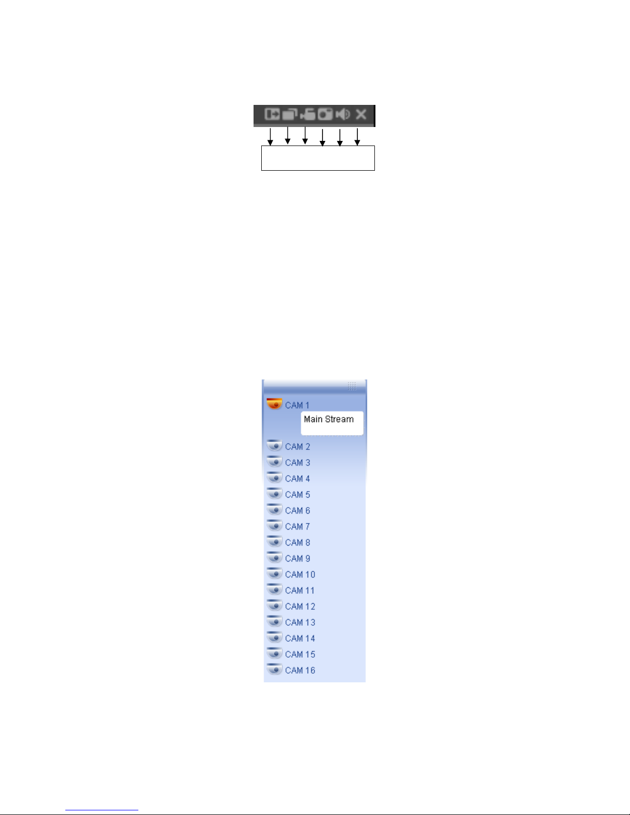
93
7.2.1 Real-time Monitor
In section 2, select the channel name you want to view. The video will play in the
selected window. For detailed function key information see Figure 7-7.
1 2 3 4 5 6
Figure 7-7
1: Digital zoom: Click this button to enable digital zoom. Now, you can left click
and drag the mouse to select a target. Right click to return.
2: Change show mode: resize or switch to full screen mode.
3: Local record: When you click local record, the system will begin recording to
your PC, and this button will become highlighted. You can go to system local
record to set video file path.
4: Capture picture: You can take a snapshot of important video. All images are
stored in the system client folder \download\picture (default).
5: Audio: Turn on or off audio. (It has no relationship with recording the audio)
6: Close video.
Refer to Figure 7-8 for main stream information.
Refresh
You can use this button to refresh camera list.
Figure 7-8
©2009 IC Realtime, Inc.
Page 94

94
Start Dialogue
You can click this button to enable two way talking.
Local Play
Click local play, and you will be prompted to open a saved video file. See Figure 7-9.
Figure 7-9
7.2.2 PTZ
Before operating a PTZ, make sure you have configured the PTZ protocol, address,
and Baud Rate. (Refer to chapter 7.3.2 Setting Pan/Tilt/Zoom).
Click the PTZ button, you will see the interface shown in Figure 7-10 .
You can click this icon to
display or hide the PTZ
control platform.
7.2.2.1 Direction Key
In Figure 7-10, there are eight direction keys.
Figure 7-10
©2009 IC Realtime, Inc.
Page 95

95
7.2.2.2 Speed
System supports eight-level speed. You can select from the dropdown list. Speed 2
is faster than speed 1.
7.2.2.3 Zoom/Focus/Iris
Here is a sheet for reference.
Name Function
key
Zoom
Focus
Iris
Function Function
key
Near
Near
close
Function
Far
Far
Open
Click the triangle icon in Figure 7-10, you will see the following interface. See Figure
7-11.
In Figure 7-11, click PTZ set, you will see the following interface. See Figure 7-12.
Figure 7-11
©2009 IC Realtime, Inc.
Page 96

96
Figure 7-12
7.2.2.4 Auto Scan
In Figure 7-12, move the camera to your desired location and then click left limit.
Next, move the camera again and then click right limit, to set a right limit.
7.2.2.5 Pattern
In Figure 7-12, you can input pattern value and then click start record, to trace PTZ
movement. Go back to Figure 7-11 to begin camera operation. Once finished, you
can click stop record. Now you have set one pattern.
7.2.2.6 Preset
In Figure 7-12, move the camera to your desired location and then input a preset
value. Click add to set this as a preset location.
7.2.2.7 Auto tour
In Figure 7-12, input an auto tour value and a preset value. Click add to set the
preset in the tour.
By repeating the above procedures you can add more presets in one tour.
7.2.2.8 Assistant
You can select the assistant item from the dropdown list. See Figure 7-13.
©2009 IC Realtime, Inc.
Page 97

97
Figure 7-13
7.2.3 Color
Click color, in section 3, the interface is shown in Figure 7-14.
Here you can select one channel and then adjust its brightness, contrast, hue and
saturation. (The selected channel has a green border).
Alternatively, you can click default, to use the default color setup.
Figure 7-14
7.2.4 Picture Path and Record Path
Click more, in Figure 7-14, and you will see the interface shown in Figure 7-15.
Figure 7-15
©2009 IC Realtime, Inc.
Page 98

98
Click picture path to choose a directory for snapshots, as in Figure 7-16.
Figure 7-16
Click record path to choose a directory for locally recorded video, as in Figure 7-17.
Figure 7-17
Clicking reboot will prompt you to reboot the system. Click OK to continue.
7.2.5 Menu Interface Switch
Put your mouse on the PTZ control bar until you see the following icon. See Figure
7-18.
Figure 7-18
Left click your mouse and then drag it to the channel control status bar. You will
notice the two menus interface switched positions. See Figure 7-19. You can
compare the following interface with Figure 7-6.
©2009 IC Realtime, Inc.
Page 99

99
7.3
7.3 Setup
Setup
7.37.3
SetupSetup
In the main window, click Setup; you will see an interface as shown in Figure 7-20.
Figure 7-19
Figure 7-20
7.3.1 System Information
Click device configuration, and you will see the following interface. See Figure 7-21.
©2009 IC Realtime, Inc.
Page 100

100
Figure 7-21
Version
Click version, and you will see corresponding HDD information for reference. See
Figure 7-22.
Figure 7-22
HDD Information
Here you can view the number of HDD’s, HDD status, total volume and free space.
See Figure 7-23.
©2009 IC Realtime, Inc.
 Loading...