

ICP C9MPD050F12B1, C9MPD075F12A1, C9MPD075F12B1, C9MPD080J16A2, C9MPD080J16B1 Installation Guide
...Page 1
INSTALLATION INSTRUCTIONS
For Extension Vent Pipe Replacement on N9MP1, N9MP2, *9MPD,
*9MPT & *9MPV Upflow Gas Furnaces.
* Denotes Brand (T, H or C)
Please read these instructions completely before attempting installation.
Parts List for Plastic Bag
Description Part# Qty.
Coupling, Discharge 1002522 1
Clamp, Hose 1013830 2
Gasket, Trap 1013701 1
SMS, #8 X 1/2" Conical 1012537 2
Clamp, 5/8"ID 1012975 2
Clamp, 3/4"ID 1012976 2
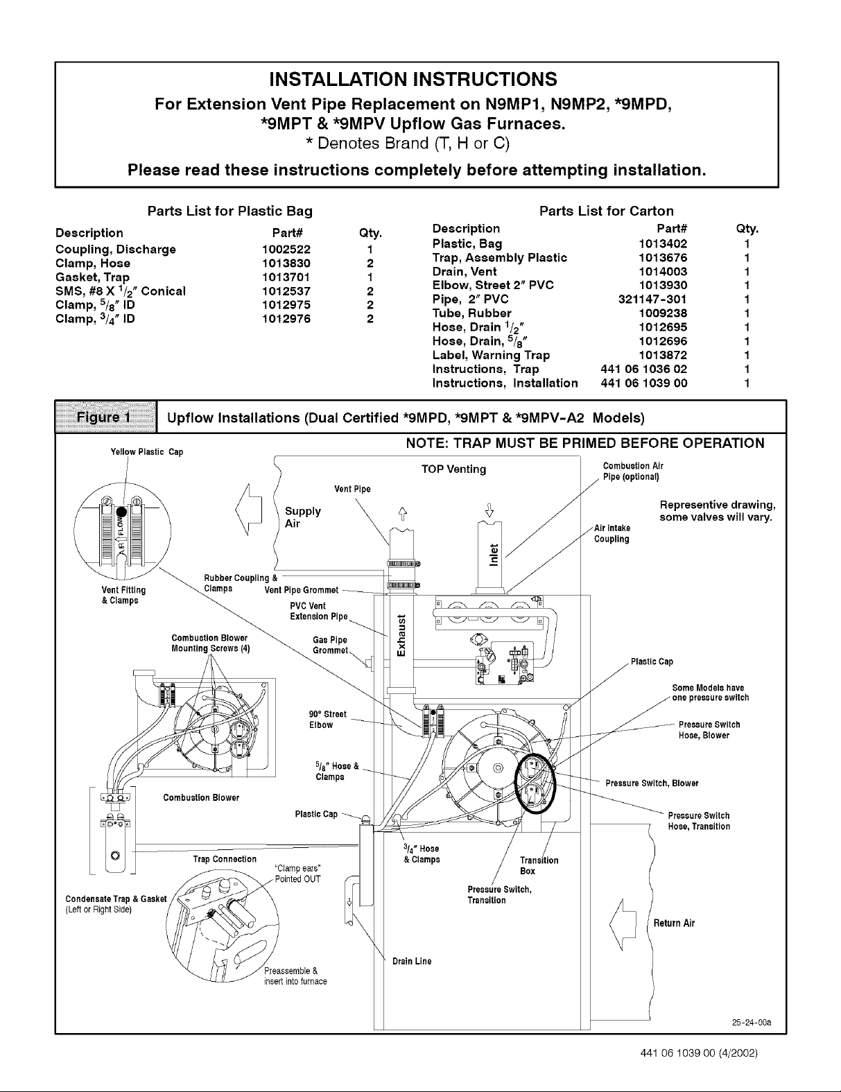
Ii Upflow Installations (Dual Certified *9MPD, *9MPT & *9MPV-A2 Models)
i
YellowPlastic Cap
VentPipe
Air
PipeGrommet
Parts List for Carton
Description Part# Qty.
Plastic, Bag 1013402 1
Trap, Assembly Plastic 1013676 1
Drain, Vent 1014003 1
Elbow, Street 2" PVC 1013930 1
Pipe, 2" PVC 321147-301 1
Tube, Rubber 1009238 1
Hose, Drain 1/2" 1012695 1
Hose, Drain, 5/8" 1012696 1
Label, Warning Trap 1013872 1
Instructions, Trap 441 06 1036 02 1
Instructions, Installation 441 06 1039 00 1
NOTE: TRAP MUST BE PRIMED BEFORE OPERATION
TOP Venting
CombustionAir
.-Air Intake
Coupling
Representive drawing,
some valves will vary.
DrainLine
PressureSwitch,
Transition
_ PtasticCaPsome Modelshave
one pressureswitch
PressureSwitch
Hose, Blower
PressureSwitch, Blower
PressureSwitch
Hose,Transition
_eturn Air
25-24-00a
441 06 1039 O0 (4/2002)
Page 2
Upflow Installations - (Dual Certified*9MPD, *9MPT &*9MPV)(See Figure 1)
NOTE: DO NOT make connections until the hose routing and
lengths have been determined. Remove the condensate trap and
drain hoses from the furnace and secure the drain hoses to the
drain stubs on the trap with the hose clamps (position the clamps as
shown in Figure 1). Install the condensate trap/hose assembly to
the furnace casing. Hook one side of the "clamp ears" on the drain
stub through the hole in the casing and push the condensate trap
into position. Secure with the two screws. Reconnect the drain
hoses to the stubs on the vent fitting and the plastic transition and
secure with the clamps.
Mount the condensate drain trap in a vertical position to either the
left or right side of the furnace using the two screws and gasket that
are provided. If needed, remove the hole plugs from the furnace
side panel and relocate to the open set of holes in the opposite side
panel.
NOTE: All gaskets and seals must be in place for sealed combus-
tion applications.
Ensure that the vent fitting and the 90 ° street elbow are securely
attached to the combustion blower using the clamps.
Plug the upper drain stub on the vent fitting with the yellow plastic
cap.
Glue the PVC vent extension pipe to the 90 ° street elbow after
checking the fit up. (Follow the procedures outlined in the Joining
Pipe and Fittings section of this manual, page 13.) Disregard the
instruction label on the PVC vent extension pipe. The orientation of
the supplied PVC vent extension pipe is not critical in the vertical
position. The PVC pipe will extend through the top panel about
21/2". Connect the rubber coupling to the end ofthe PVC extension
pipe using the clamp.
NOTE: There will be some misalignment ofthe PVC pipe inside the
furnace. The rubber coupling will straighten outthe misalignment at
the vent pipe connection at the top of the furnace.
For left side venting, remove 90 ° street elbow from the vent fitting
by loosening the clamp on the vent fitting. Securely attach vent fit-
ting to combustion blower.
NOTE: For left side venting, the vent fitting MUST be installed with
the airflow marking arrow pointed toward the vent pipe, with the
drain stub at a 5° to 10 ° downward slope.
Connect the PVC vent extension pipe to the vent fitting. This pipe
has a built-in channel to assist vent condensate disposal.
Align the arrow on the PVC pipe with the airflow marking arrow on
the vent fitting. See label on the PVC pipe for proper installation.
This pipe may only be shortened if an elbow is used to connect the
PVC vent extension tube to field-installed vent pipe. Securely at-
tach the PVC vent extension pipe to the vent fitting with the clamp.
This configuration allows left side venting from the furnace. If right
side venting is required, the combustion blower must be relocated
on the plastic transition box. Loosen the four(4) screws that secure
the blower to the transition approximately1/2 ", Rotate the blower
180 ° and secure with the four(4) screws. Note that some combus-
tion blowers have plastic spacers on the mounting legs of the blow-
er located atthe 6 and 12 o'clock positions (blower snout to the left
or right) that are required for proper fit up of the blower to the transi-
tion. Use caution to not over tighten the screws to prevent stripping
out of the plastic mounting holes.
NOTE: For right side venting, the vent fitting MUST be installed with
the airflow marking arrow pointed toward the vent pipe, with the
drain stub at a 5 ° to 10 ° downward slope. (See Figure 2)
Plug the upper drain stub on the vent fitting with the yellow plastic
cap.
Connect the PVC vent extension pipe to the vent fitting. This pipe
has a built-in channel to assist vent condensate disposal.
Align the arrow on the PVC pipe with the airflow marking arrow on
the vent fitting. See label on the PVC pipe for proper installation.
This pipe may only be shortened if an elbow is used to connect the
PVC vent extension tube to field-installed vent pipe. Securely at-
tach the PVC vent extension pipe to the vent fitting with the clamp.
For left side mounted condensate trap, connect the 3/4" OD rubber
hose with the 90 ° bend to the large drain stub on the condensate
trap and secure with a 3/4" clamp.
Route the hose to the drain stub on the bottom ofthe plastic transi-
tion box. Cut off excess hose and discard. Connect the hose to the
drain stub on the transition and secure with a 3/4" clamp.
For right side mounted condensate trap, connect the 3/4" OD rub-
ber hose with the 90 ° bend to the bottom of the plastic transition box
and secure with a 3/4" clamp.
Route the hose to the large drain stub on the condensate trap. Cut
off excess hose and discard. Connect the hose to the drain stub on
the condensate trap and secure with a 3/4" clamp.
Connect the 5/8" OD rubber hose with the 90 ° bend to the lower
drain stub on the vent fitting and secure with a 5/8" clamp.
441 06 1039 O0 - 2 -
Page 3
iiiiiiiiiiiiiiiiil;i!¸I!I¸!i¸i!!gilililil¸¸ll_ggilll!_!iiiiiillll!l!l!l!l!l!gl_l_l_l_l_l_l_l_l_l_l_l_l_l_l_l_l_l_l_l_l_l_!
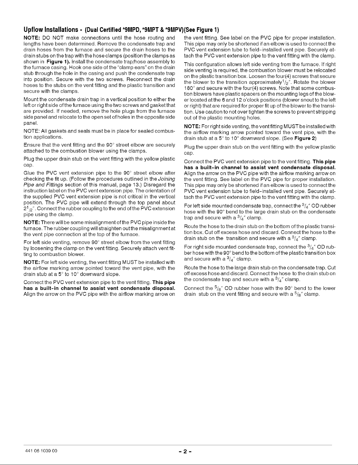
Upflow Installations (Dual Certified *9MPD, *9MPT & *9MPV-A2 Models)
RIGHT Side Venting
Supply Air
Some Models
have one
0
DRAIN SIDE VIEW
Rotate
5° to10°
Vent
Drain
angled5° to 10° also.
For left or right side mounted condensate trap, the pressure tap
on the condensate trap MUST be connected to the unused pres-
sure tap located on the upper right hand corner of the plastic transi-
tion box. Remove the plastic caps from the pressure taps on the
condensate trap and the plastic transition and connect with the
5/16"OD rubber hose. (See Figure 1 and Figure 2)
NOTE: TRAP MUST BE PRIMED BEFORE OPERATION
Representive drawing,
some valves will vary.
Vent Fitting
&Clamps
PVCVent
ExtensionPipe
TrapConnection
_PointedOUT
Return
Air
'_Clampears"
Preassemble
andinsert
25-24-05
Route the hose to the small drain stub on the condensate trap. Cut
off excess hose and discard, Connect the hose to the drain stub on
the trap and secure with a 5/8" clamp.
NOTE: Route hoses to the condensate trap with no kinking or bind-
ing for proper condensate drainage.
int0furnace
441 06 1039 O0 - 3 -
Page 4
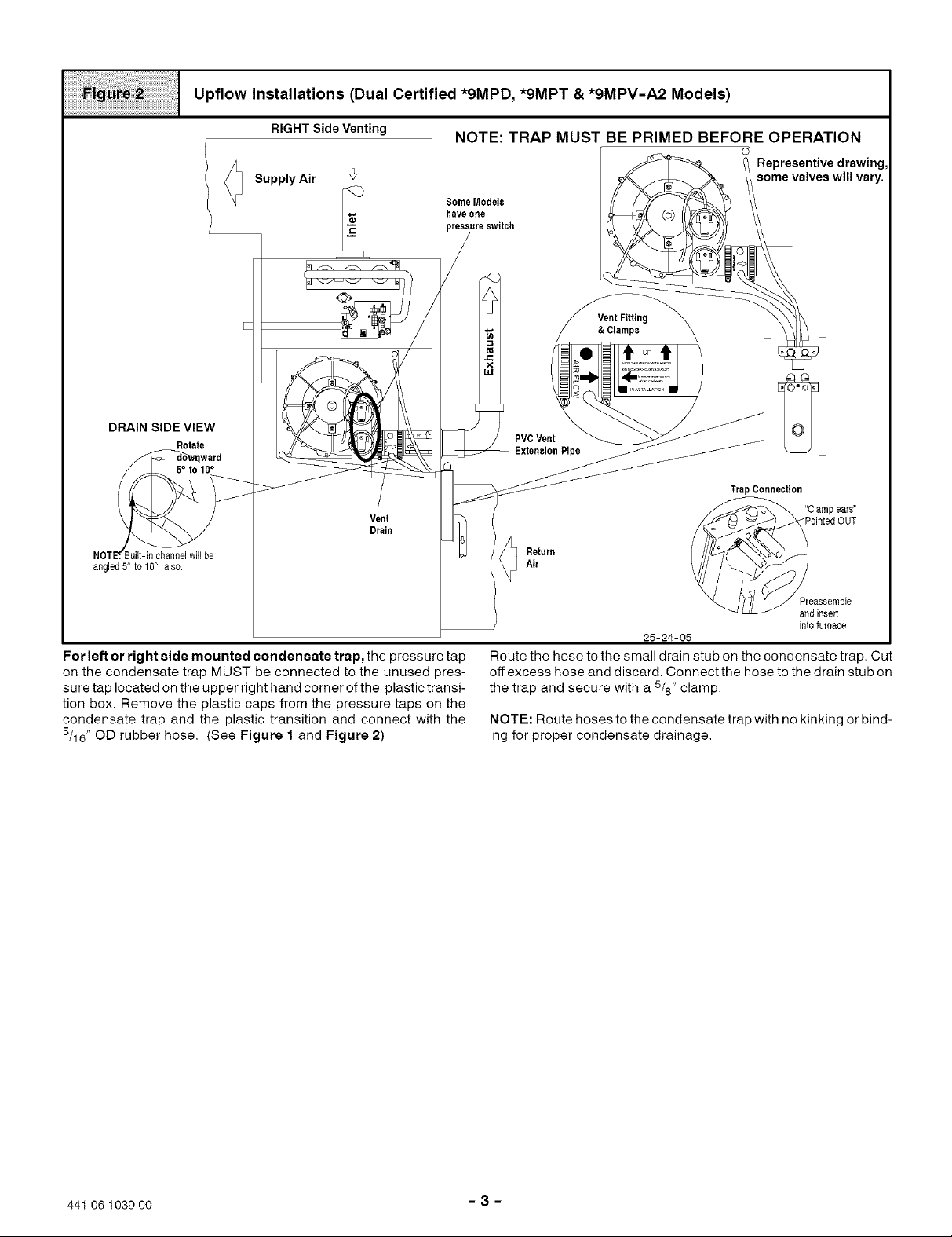
Horizontal Left Installations (Dual Certified *9MPD,*9MPT,*9MPV-A2 Models)
CombustionAir
ipe
Pipe,(optional)
Supply
Air
PVCVent
ExtensionPipe
Vent Fitting
&Clamps
Yellow
Plastic 5/8" Hose
Airlntake $omeModete NOTE: TRAP MUST BE PRIMED BEFORE OPERATION
Coul have one
5/16" OD TransitionBox PressureSwitch, PressureSwitch, Representive drawing,
Rubber Blower somevalveswill vary.
Blower
Return
Air
VentPipe
90° Street & Clamps
Elbow
DRAIN SIDEVIEW
• Rotate
Gas Pipe
Grommet f [,<7- do_ward
RubberCoupling
CombustionBlower
g Screws
Transition
HorizontalTrap Connection
Rose,
Ipears"
PointedOUT
NOTE_.Built-in channelwill be
angled5° to 10° also.
Horizontal Left Installations - (Dual Certified*9MPD, *9MPT &*9MPV) (SeeFigure3)
Note: DO NOT make hose connections until the hose routing and
lengths have been determined, Remove the condensate trap and
drain hoses from the furnace and secure the drain hoses to the
drain stubs on the trap with the hose clamps (position the clamps as
shown in Figure 3). Install the condensate trap/hose assembly to
the furnace casing, Hook one side of the "clamp ears" on the drain
stub through the hole in the casing and push the condensate trap
into position. Secure with the two screws. Reconnect the drain
hoses to the stubs on the vent fitting and the plastic transition and
secure with the clamps.
Relocate the plastic cap and clamp from the vertical transition drain
stub to the horizontal transition drain stub on the condensate drain
trap. Secure the clamps tightly to prevent condensate leakage. Do
not change the cap and clamp on the vent drain stub.
Mount the condensate drain trap in a vertical position to the left side
of the furnace using the two screws and gasket that are provided.
Note: The condensate trap will be located under the furnace in a
vertical position when the furnace is placed horizontally on the left
side. If needed, remove the hole plugs from the furnace side panel
and relocate to the open set of holes in the opposite side panel.
NOTE: All gaskets and seals must be in place for sealed combus-
tion applications.
Remove the 90 ° street elbow and vent fitting from the combustion
blower by loosening the clamps on the vent fitting. Connect the 90 °
street elbow to the combustion blower using the rubber coupling
and clamps. Glue a 11" section of PVC pipe (field supplied) to the
90 ° street elbow after checking the fit up. (Follow the procedures
outlined in the Joining Pipe and Fittings section of this manual,
page 13.) The PVC pipe will extend through the top panel about
441 06 1039 00 - 4 -
11/2"• Connect the vent fitting to the end of the 11" section of PVC
pipe using the clamp.
NOTE: The vent fitting MUST be installed with the airflow marking
arrow pointed toward the vent pipe, with the drain stub at a5°to 10°
downward slope.
Plug the upper drain stub on the vent fitting with the yellow plastic
cap.
Connect the PVC vent extension pipe to the vent fitting. This pipe
has a built-in channel to assist vent condensate disposal.
Align the arrow on the PVC pipe with the airflow marking arrow on
the vent fitting• See label on the PVC pipe for proper installation,
This pipe may only be shortened if an elbow is used to connect the
PVC vent extension tube to field-installed vent pipe, Securely at-
tach the PVC vent extension pipe to the vent fitting with the clamp.
Connect the 5/8" OD rubber hose with the 90° bend to the lower
drain stub on the vent fitting and secure with a 5/8" clamp.
Route the hose to the horizontal drain stub on the condensate trap.
Cut off excess hoses and discard. Connect the hose to the drain
stub on the condensate trap and secure with a 5/8" clamp.
Connect the 3/4" OD rubber hose with the 90° bend to the large
drain stub on the condensate trap and secure with a 3/4" clamp.
Route the hose to the drain stub on the bottom ofthe plastic transi-
tion box• Cut off excess hose and discard. Connect the hose to the
drain stub on the transition and secure with a 3/4" clamp.
The pressure tap on the condensate trap MUST be connected to
the unused pressure tap located on the top of the plastic transition
box• Remove the plastic caps from the pressure taps on the con-
Preassembleand
insertintofurnace
25-24-09
Page 5
densatetrapandtheplastictransitionandconnectwiththe5/16"
ODrubberhose.
NOTE:Thiswillrequiredrillinga5/16"ODholeinthefurnacecasing
nexttothecondensatetrap.
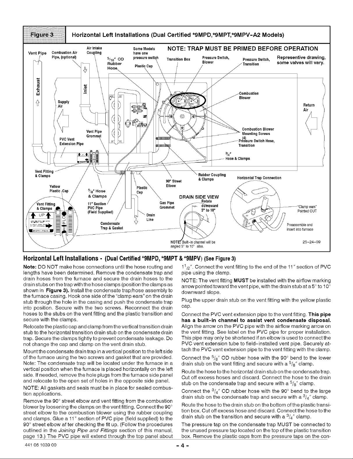
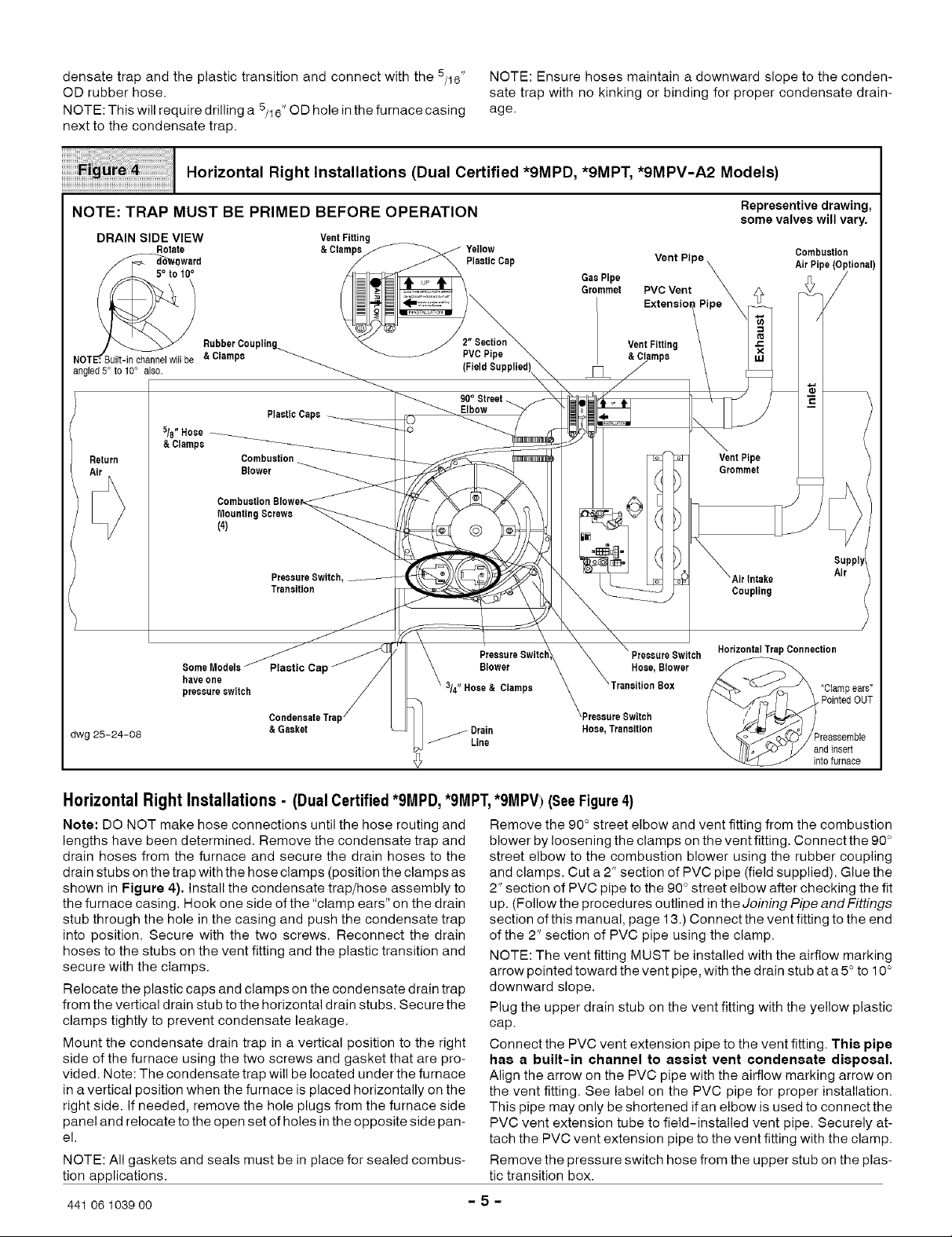
Horizontal Right Installations (Dual Certified *9MPD, *9MPT, *9MPV-A2 Models)
NOTE:Ensurehosesmaintainadownwardslopetotheconden-
satetrapwithnokinkingorbindingforpropercondensatedrain-
age.
NOTE: TRAP MUST BE PRIMED BEFORE OPERATION
DRAIN SIDE VIEW VentFitting
_ward f _ _ PlaaticCap
j _ RubberCoupling._ _ /" 2[.Secyion
NOTE_':Built-inchannelwillbe &Clamps _ _ PVCPipe ..
angled 5° to 10° als0. _ (Field Bupplied)\_
Return
Rotate &Clampe_ Yellow
90° Street-__ _ _ c
5/8"Hose _ PlasticCaps_ -1_ _
&Clamps __ _
Combustion _ qo _' _ VentPipe
CombustionBlowek_ _ E
MountingScrews _ O _ )
(4)
Blower _i_c ,___ _ G_ommet I_/_
Transition _<_ __ Coupling
PreaeureSwitch,__ )_'\__o__ Airlntake Air
Representive drawing,
some valves will vary.
Combustion
GasPipe
Grommet
_ _ / Supply
Vent Pipe X
PVCVent _ _¢
Extenoi°n/PiPe _i
V&e;tFmit;isng \ x
AirPipe(Optional)
/
/
3/4"Hose& Clamps --Transition Box ,,pOplart Pde_rus,T
dwg 25-24-08
!ieV_20_ide_t_C_e_ill ' \\ BIowerPressureSwitch_,,_ \Preeeare_X Hose,BIowerSWitch/_> _J\_H°riz°ntalTrapConnection
r i / _'_/_
Horizontal Right Installations - (Dual Certified*9MPD, *9MPT,*9MPV) (SeeFigure4)
Note: DO NOT make hose connections until the hose routing and
lengths have been determined. Remove the condensate trap and
drain hoses from the furnace and secure the drain hoses to the
drain stubs on the trap with the hose clamps (position the clamps as
shown in Figure 4). Install the condensate trap/hose assembly to
the furnace casing. Hook one side of the "clamp ears" on the drain
stub through the hole in the casing and push the condensate trap
into position. Secure with the two screws. Reconnect the drain
hoses to the stubs on the vent fitting and the plastic transition and
secure with the clamps.
Relocate the plastic caps and clamps on the condensate drain trap
from the vertical drain stub to the horizontal drain stubs. Secure the
clamps tightly to prevent condensate leakage.
Mount the condensate drain trap in a vertical position to the right
side of the furnace using the two screws and gasket that are pro-
vided. Note: The condensate trap will be located under the furnace
in a vertical position when the furnace is placed horizontally on the
right side. If needed, remove the hole plugs from the furnace side
panel and relocate to the open set of holes in the opposite side pan-
el.
NOTE: All gaskets and seals must be in place for sealed combus-
tion applications.
441 06 1039 oo - 5 -
Remove the 90 ° street elbow and vent fitting from the combustion
blower by loosening the clamps on the vent fitting. Connect the 90 °
street elbow to the combustion blower using the rubber coupling
and clamps. Cut a 2" section of PVC pipe (field supplied). Glue the
2" section of PVC pipe to the 90 ° street elbow after checking the fit
up. (Follow the procedures outlined in the Joining Pipe and Fittings
section of this manual, page 13.) Connect the vent fitting to the end
of the 2" section of PVC pipe using the clamp.
NOTE: The vent fitting MUST be installed with the airflow marking
arrow pointed toward the vent pipe, with the drain stub at a 5° to 10 °
downward slope.
Plug the upper drain stub on the vent fitting with the yellow plastic
cap.
Connect the PVC vent extension pipe to the vent fitting. This pipe
has a built-in channel to assist vent condensate disposal.
Align the arrow on the PVC pipe with the airflow marking arrow on
the vent fitting. See label on the PVC pipe for proper installation.
This pipe may only be shortened if an elbow is used to connect the
PVC vent extension tube to field-installed vent pipe. Securely at-
tach the PVC vent extension pipe to the vent fitting with the clamp.
Remove the pressure switch hose from the upper stub on the plas-
tic transition box.
\ II_lo_o" _1 aodinsert
_ int0furnace
Page 6

Relocatetheplasticcapsonthestubsoftheplastictransitionbox
fromthelowerstubstotheupperstubsandsecuretightlywiththe
clamps.
Routethepressureswitchhosetothelowerstubontheplastic
transitionbox.Cutoffexcesshoseanddiscard.Connectthepres-
sureswitchhosetothelowerstubontheplastictransitionbox.En-
surethatthehoseisroutedabovethestubonthetransitionboxso
thatcondensatedoesnotcollectinthehose.NOTE:Failuretocor-
rectlyinstallthepressureswitchhosetothetransitioncanadverse-
lyaffectthesafetycontroloperation.
Connectthe3/4"ODrubberhosewiththe90° bendtothelarge
iiiiiiiiiiiiiiiii¸iiiiiiiiiiiiiiii_ii;iiiiiiiiiii¸i¸i¸i¸i¸i¸i¸i!il¸i¸i¸iiiiiiiiiii!!iiiiiiiiiiiiiiiiiiiiiiiiiiii!!i
NOTE: TRAP MUST BE PRIMED BEFORE OPERATION
DRAIN SIDE VIEW
Rotate
5° tot0 °
LEFT Side Venting
<Z>
drainstubonthecondensatetrapandsecurewitha3/4"clamp.
Routethehosetothedrainstubonthebottomoftheplastictransi-
tionbox.Cutoffexcesshoseanddiscard.Connectthehosetothe
drainstubonthetransitionandsecurewitha3/4"clamp.
Connectthe5/8"ODrubberhosewiththe90°bendtothelower
drainstubontheventfittingandsecurewitha5/8"clamp.
Routethehosetothesmallerdrainstubonthecondensatetrap.
Cutoffexcesshoseanddiscard.Connectthehosetothedrain
stubonthetrapandsecurewitha5/8"clamp.
NOTE:Routehosestothecondensatetrapwithnokinkingorbind-
ingforpropercondensatedrainage.
RIGHT Side Venting
<Z>
_uilt-in channel will be
angled5 ° to 10° als0.
Horizontal
Trap Connection
PVCVent
Extension
Pipe
ReturnAir
PressureSwitch
Some Models Hose,Traneitio_--
haveone
pressureowi_nbaotion Blower
Screws (4)
Preoaar_
Switch,
Blower-
Preoear(
Switch
Hose,
CombustionBlower
(Rotate 180° for
PreooareSwitch,
Transition
Transition
Box
& Clamps
ReturnAir
Clamps
Representive drawing
some valves will vary.
AirIntake AirPipe,(Optional)
Coupling
Combustion
/
Ven/tPipe
_0 Vent
:oo,oo
PlasticCaps
VentPiPGromm_
Condensate
Trap&Gasket
GasPipe
Grommet
DrainLine
Vent Fitting
SupplyAir
<Z>
SupplyAir
<Z>
Preaeeemble
andinsert
intofurnace
"Clamp ears"
PointedOUT
Downflow Installations - (Dual Certified *9MPD, *9MPT,*9MPV Models) (SeeFigure5)
NOTE: DO NOT make hose connections until the hose routing and
lengths have been determined. Remove the condensate trap and
drain hoses from the furnace and secure the drain hoses to the
drain stubs on the trap with the hose clamps (position the clamps as
shown in Figure 5). Install the condensate trap/hose assembly to
the furnace casing. Hook one side of the "clamp ears" on the drain
stub through the hole in the casing and push the condensate trap
into position. Secure with the two screws. Reconnect the drain
441 06 1039 oo
hoses to the stubs on the vent fitting and the plastic transition and
secure with the clamps.
Mount the condensate drain trap in a vertical position to either the
right or left side of the furnace using the two screws and gasket that
are provided. If needed, remove the hole plugs from the furnace
side panel and relocate to the open set of holes in the opposite side
panel.
-6-
dwg 25-24-07
Page 7

NOTE: All gaskets and seals must be in place for sealed combus-
tion applications.
For both right and left side vent, remove the 90 ° street elbow
from the vent fitting by loosening the clamp on the vent fitting.
Ensure that the vent fitting is securely attached to the combustion
blower using the rubber coupling and clamps,
Connect the PVC vent extension pipe to the vent fitting. This pipe
has a built-in channel to assist vent condensate disposal.
Align the arrow on the PVC pipe with the airflow marking arrow on
the vent fitting. See label on the PVC pipe for proper installation.
This pipe may only be shortened if an elbow is used to connect the
PVC vent extension tube to field-installed vent pipe. Securely at-
tach the PVC vent extension pipe to the vent fitting with the clamp.
This configuration allows left side venting from the furnace. If right
side venting is required, the combustion blower must be relocated
on the plastic transition box. Loosen the four(4) screws that secure
the blower to the transition approximately1/2 ". Rotate the blower
180 ° and secure with the four(4) screws. Note that some combus-
tion blowers have plastic spacers on the mounting legs ofthe blow-
er located at the 6 and 12 o'clock positions (blower snout to the left
or right) that are required for proper fit up of the blower to the transi-
tion. Use caution to not over tighten the screws to prevent stripping
out of the plastic mounting holes.
NOTE: The vent fitting MUST be installed with the airflow marking
arrow pointed toward the vent pipe, with the drain stub at a 5° to 10 °
downward slope.
Plug the upper drain stub on the vent fitting with the yellow plastic
cap.
Connect the PVC vent extension pipe to the vent fitting. This pips
has a built-in channel to assist vent condensate disposal.
Align the arrow on the PVC pipe with the airflow marking arrow on
the vent fitting. See label on the PVC pipe for proper installation.
This pipe may only be shortened if an elbow is used to connect the
PVC vent extension tube to field-installed vent pipe. Securely at-
tach the PVC vent extension pipe to the vent fitting with the clamp.
Remove the pressure switch hose from the upper stub on the plas-
tic transition box.
Relocate the plastic caps on the stubs of the plastic transition box
from the lower stubs to the upper stubs and secure tightly with the
clamps.
Route the pressure switch hose to the lower stub on the plastic
transition box. Cut off excess hose and discard. Connect the pres-
sure switch hose to the lower stub on the plastic transition box.
NOTE: Failure to correctly install the pressure switch hose to the
transition box can adversely affect the safety control operation.
Connect the 3/4" OD rubber hose with the 90 ° bend to the drain stub
on the bottom of the plastic transition box and secure with a 3/4"
clamp.
Route the hose to the large drain stub on the condensate trap. Cut
off excess hose and discard. Connect the hose to the drain stub on
the transition and secure with a 3/4" clamp.
Connect the 5/8" OD rubber hose with the 90 ° bend to the lower
drain stub on the vent fitting and secure with a 5/8" clamp.
Route the hose to the smaller stub on the condensate trap. Cut off
excess hose and discard. Connect the hose to the drain stub on the
trap and secure with a 5/8" clamp.
For left side or right side mounted condensate trap, the pres-
sure tap on the condensate trap MUST be connected to the unused
pressure tap located on the top of the plastic transition box. Re-
move the plastic caps from the pressure tap on the condensate trap
and the plastic transition and connect the 5/16" OD rubber hose.
(See Figure 5)
NOTE: Route hoses to the condensate trap with no kinking or bind-
ing for proper condensate drainage.
441 06 1039 oo - 7 -
Page 8

iiiiiiiiiiiiiiiiil;i!¸I!I¸!i¸i!!i;i¸iiiilil¸¸lllii_lllllll!_!iiiiiillll!l!l!l!l!llllll_l_l_l_l_l_l_l_l_l_l_l_l_l_l_l_l_l_l_l_l_l_!
Upflow Installations (Single Pipe & Direct Vent N9MP1 & N9MP2-A2 Models)
NOTE: TRAP MUST BE PRIMED BEFORE OPERATION
VentFitting SupplyAir
DRAIN SIDEVIEW 0 I
!B &Clamps PVCVent
: • _. •NOT u_lt_nchannelw_ll
beangled5° to 10° also. VentPi
Combustion Blower
MountingScrews(4)
VentFitting&Clamps
90= VentPipe
Condensate
Trap& Gasket
DrainLine
TrapConnection
5/8"Hose& Clamps
ExtensionPipe
Grommet
LEFT Side Venting
& Clamps
Transition
Box
SomeModelshaveone
pressureswitch
CombasUon
N9MP2ONLY
Combaetion Blower
(Rotate 180° for
RightSide)
PlasticCap
PressureHose,
Blower
I, Blower
PressureSwitchHose,
Transition
PressureSwitch, Transition
Return
Air
_/ PointedOUT
"Ctampears"
/ Representive drawing,
J Preaeeemble& some valves will vary.
insertintofurnace
Upflow Installations - (Single Pipe & DirectVent N9MP1 &
N9MP2 Models) (See Figure 6)
NOTE: DO NOT make hose connections until the hose routing and
lengths have been determined. Remove the condensate trap and
drain hoses from the furnace and secure the drain hoses to the
drain stubs on the trap with the hose clamps (position the clamps as
shown in Figure 6). Install the condensate trap/hose assembly to
the furnace casing. Hook one side of the "clamp ears" on the drain
stub through the hole in the casing and push the condensate trap
into position. Secure with the two screws. Reconnect the drain
hoses to the stubs on the vent fitting and the plastic transition and
secure with the clamps.
Mount the condensate drain trap in a vertical position to either the
left or right side of the furnace using the two screws and gasket that
are provided. If needed, remove the hole plugs from the furnace
side panel and relocate to the open set of holes in the opposite side
panel.
NOTE: All gaskets and seals must be in place for sealed combus-
tion applications.
Ensure that the vent fitting is securely attached to the combustion
blower using the rubber coupling and clamps.
NOTE: For left side venting, the vent fitting MUST be installed with
the airflow marking arrow pointed toward the vent pipe, with the
drain stub at a 5° to 10 ° downward slope.
Connect the PVC vent extension pipe to the vent fitting. This pipe
has a built-in channel to assist vent condensate disposal.
Align the arrow on the PVC pipe with the airflow marking arrow on
441 06 1039 00 - 8 -
dwg 25-24-06
the vent fitting. See label on the PVC pipe for proper installation.
This pipe may only be shortened if an elbow is used to connect the
PVC vent extension tube to field-installed vent pipe. Securely at-
tach the PVC vent extension pipe to the vent fitting with the clamp.
This configuration allows left side venting from the furnace. If right
side venting is required, the combustion blower must be relocated
on the plastic transition box. Loosen the four(4) screws that secure
the blower to the transition approximately1/2 ". Rotate the blower
180 ° and secure with the four(4) screws. Note that some combus-
tion blowers have plastic spacers on the mounting legs of the blow-
er located atthe 6 and 12 o'clock positions (blower snout to the left
or right) that are required for proper fit up of the blower to the transi-
tion. Use caution to not over tighten the screws to prevent stripping
out of the plastic mounting holes.
NOTE: For right side venting, the vent fitting MUST be installed with
the airflow marking arrow pointed toward the vent pipe, with the
drain stub at a 5 ° to 10 ° downward slope. (See Figure 7)
Plug the upper drain stub on the vent fitting with the yellow plastic
cap.
Connect the PVC vent extension pipe to the vent fitting. This pipe
has a built-in channel to assist vent condensate disposal.
Align the arrow on the PVC pipe with the airflow marking arrow on
the vent fitting. See label on the PVC pipe for proper installation.
This pipe may only be shortened if an elbow is used to connect the
PVC vent extension tube to field-installed vent pipe. Securely at-
tach the PVC vent extension pipe to the vent fitting with the clamp.
Page 9
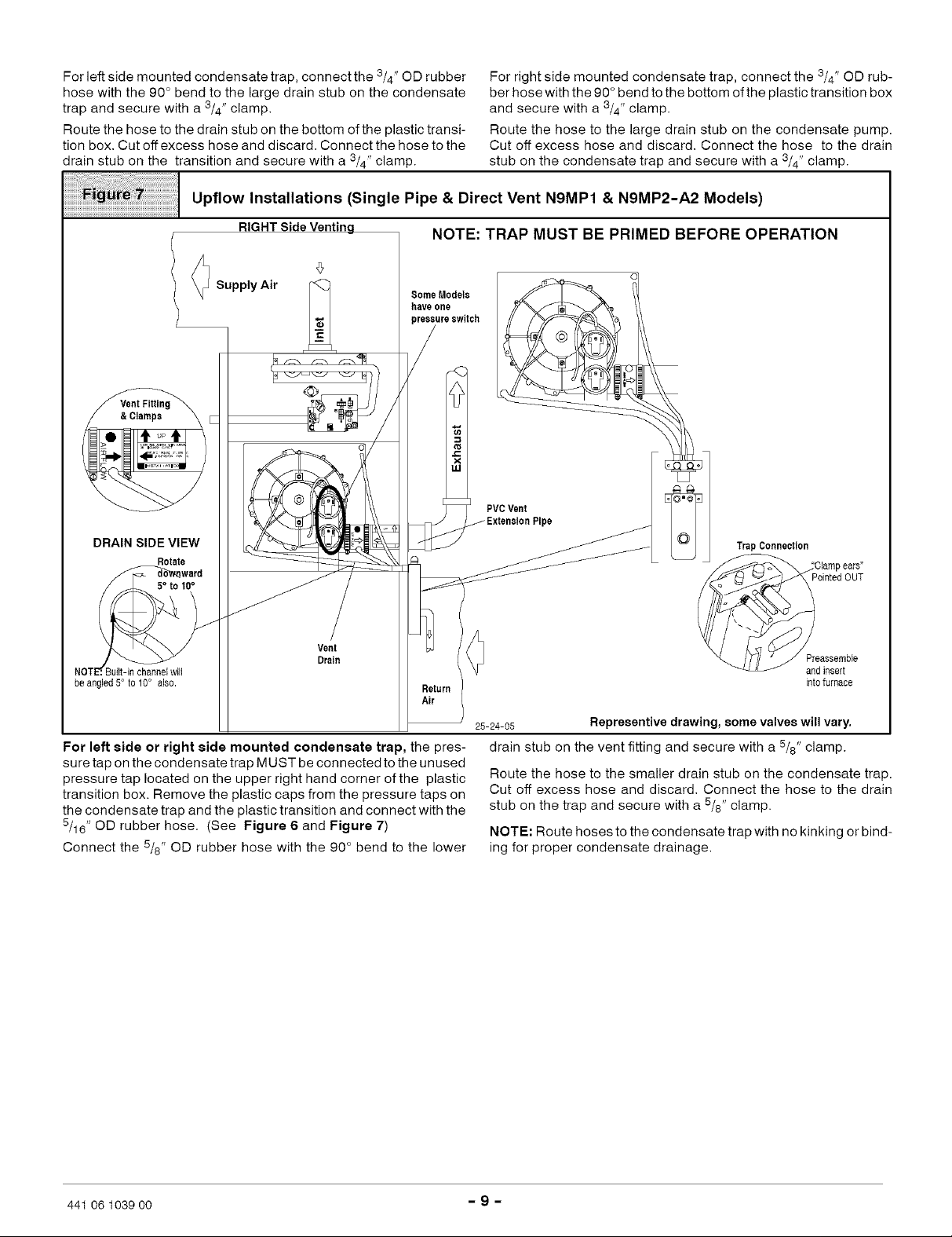
Forleftsidemountedcondensatetrap,connectthe3/4"ODrubber
hosewiththe90°bendtothelargedrainstubonthecondensate
trapandsecurewitha 3/4" clamp.
Route the hose to the drain stub on the bottom of the plastic transi-
tion box. Cut off excess hose and discard. Connect the hose to the
drain stub on the transition and secure with a 3/4" clamp.
Upflow Installations (Single Pipe & Direct Vent N9MP1 & N9MP2-A2 Models)
RIGHTSideVentinq NOTE: TRAP MUST BE PRIMED BEFORE OPERATION
For right side mounted condensate trap, connect the 3/4" OD rub-
ber hose with the 90 ° bend to the bottom of the plastic transition box
and secure with a 3/4" clamp.
Route the hose to the large drain stub on the condensate pump.
Cut off excess hose and discard. Connect the hose to the drain
stub on the condensate trap and secure with a 3/4" clamp.
Supply Air
DRAIN SIDE VIEW
Rotate
5° to t0°
Vent
Drain
}uilt-in channel will
be angled 5° to 10° als0.
Some Models
haveone
reesureswitch
For left aide or right aide mounted condenaate trap, the pres-
sure tap on the condensate trap MUST be connected to the unused
pressure tap located on the upper right hand corner of the plastic
transition box. Remove the plastic caps from the pressure taps on
the condensate trap and the plastic transition and connect with the
5/16"OD rubber hose. (See Figure 6 and Figure 7)
Connect the 5/8" OD rubber hose with the 90° bend to the lower
PVCVent
25-24-05
drain stub on the vent fitting and secure with a 5/8" clamp.
Route the hose to the smaller drain stub on the condensate trap.
Cut off excess hose and discard. Connect the hose to the drain
stub on the trap and secure with a 5/8" clamp.
NOTE: Route hoses to the condensate trap with no kinking or bind-
ing for proper condensate drainage.
ipe
TrapConnection
Pointed OUT
Preassembte
andinsert
intofurnace
Representive drawing, some valves will vary.
441 06 1039 00 - 9 -
Page 10

iiiiiiiiiiiiiiiiiil;;_!¸I!I¸!i¸i!_i;i;i;i;i;iiiiiiii;:iiiiiiiiiiiiii!i;il;;iiii¸ii¸iil;i;i;i;i;i;i;i;i;i;i;i;i;i;i;i;i;i;i;i;i;i;i;
Horizontal Left Installations (Single Pipe & Direct Vent N9MP1 & N9MP2-A2 Models)
NOTE: TRAP MUST BE PRIMED BEFORE OPERATION
Vent P
VentPipe
/ VentFitting
S)
.c
x
uJ
Vent Fitting& Clamps
l Clamps
Supply
Air
> Inlet
/
Combustion
AirPipe,
N9MP2ONLY
L_
CombustionBtowel
(Rotate 180° for Right Side)
MountingScrews(4)
DrainLine
Representive drawing, some valves will vary.
Horizontal Left Installations- (Single Pipe& Direct Vent
NOTE: DO NOT make hose connections until the hose routing and
lengths have been determined. Remove the condensate trap and
drain hoses from the furnace and secure the drain hoses to the
drain stubs on the trap with the hose clamps (position the clamps as
shown in Figure 8). Install the condensate trap/hose assembly to
the furnace casing. Hook one side of the "clamp ears" on the drain
stub through the hole in the casing and push the condensate trap
into position. Secure with the two screws. Reconnect the drain
hoses to the stubs on the vent fitting and the plastic transition and
secure with the clamps.
Relocate the plastic caps and clamps on the condensate drain trap
from the vertical drain stubs to the horizontal drain stubs. Secure
the clamps tightly to prevent condensate leakage.
Mount the condensate drain trap in a vertical position to the left side
of the furnace using the two screws and gasket that are provided.
Note: The condensate trap will be located under the furnace in a
vertical position when the furnace is placed horizontally on the left
side. if needed, remove the hole plugs from the furnace side panel
and relocated to the open set of holes in the opposite side panel.
NOTE: All gaskets and seals must be in place for sealed combus-
tion applications.
Relocate the combustion blower on the plastic transition box. Re-
move the four(4) screws that secure the blower to the transition
box. Rotate the blower 180 ° so the blower snout is pointing up and
PressureSwitch Hose, Transition
Transition
one pressureswitch
Blower
PressureSwitch Hose, Blower
TransitionBox
518"Hose& Clamps
' Hose & Clamps
PlasticCap
Trap &Gasket
dw_ 25-23-58
Horizontal Trap Connection
Return
Air
"Clampears"
PointedOUT
semble
sert
intofurnace
NgMP1 & NgMP2 Models) (See Figure 8)
secure with the four(4) screws. Note that some combustion blow-
ers have plastic spacers on the mounting legs of the blower located
at the 6 and 12 o'clock positions (blower snout to the left or right)
that are required for proper fit up of the blower to the transition. Use
caution to not over tighten the screws to prevent stripping out of the
plastic mounting holes.
Ensure that the vent fitting is securely attached to the combustion
blower using the rubber coupling and clamps.
NOTE: The vent fitting MUST be installed with the airflow marking
arrow pointed toward the vent pipe.
Plug the left drain stub on the vent fitting with the yellow plastic cap.
Connect the 3/4" OD rubber hose with the 90 ° bend to the large
drain stub on the condensate trap and secure with a 3/4" clamp.
Route the hose to the drain stub on the bottom ofthe plastic transi-
tion box. Cut off excess hose and discard. Connect the hose to the
drain stub on the transition and secure with a 3/4" clamp.
Connect the 5/8" OD rubber hose with the 90 ° bend to the right drain
stub on the vent fitting and secure with a 5/8" clamp.
Route the hose to the smaller drain stub on the condensate trap.
Cut off excess hose and discard. Connect the hose to the drain
stub on the vent fitting and secure with a 5/8" clamp.
NOTE: Route hoses to the condensate trap with no kinking or bind-
ing for proper condensate drainage.
441 06 1039 00 - 10 -
Page 11
iiiiiiiiiiiiiiiiil_!i!i!i!i!_i!_!i!i!i!iii;l!:;!%!i_iliiiiiiiiiiiiiiiiiiiiiliiiiiiiiil_iiiiiiiiiiili%iiiiiiiiiiiilii
i!i!i!i!i!i!i!i!i!i!i!iiii ii ii i! i ii ii i ii ii i! i ii ii ii ii ii ii ii ii ii ii ii iiiiiiiiiiiiiiiiiiiiili
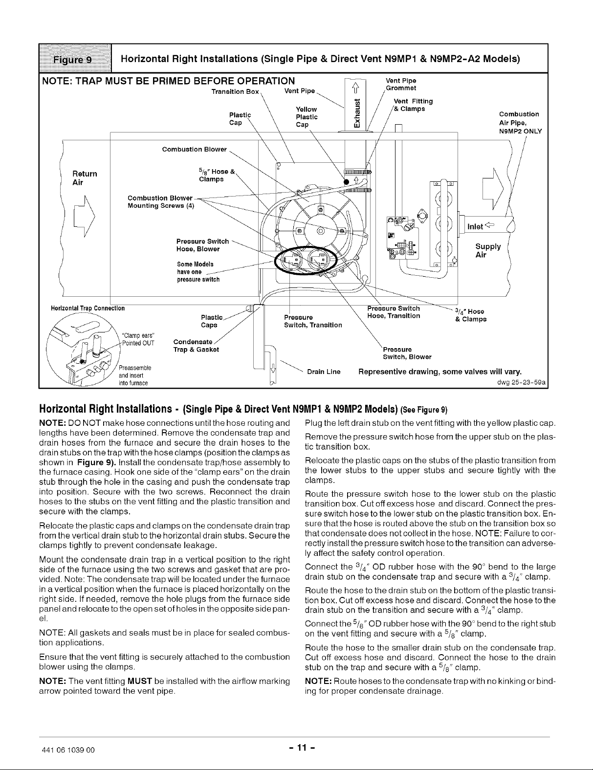
Horizontal Right Installations (Single Pipe & Direct Vent N9MP1 & N9MP2-A2 Models)
NOTE: TRAP MUST BE PRIMED BEFORE OPERATION
Transition Box
Plastic Combustion
Cap Air Pipe,
Combustion Blower
Return
Air
Horizontal TrapConnection
Combustion Blower-
Mounting Screws (4)
"Clampears"
PointedOUT
'reassemble
andinsert
into furnace
5/8"
Clamps
Pressure Switch
Hose, Blower
SomeModels
haveone
pressureswitch
Plastic
Caps
Condensate
Trap & Gasket
Pressure
Switch, Transition
Drain Line
Vent Pipe
Grommet
Vent Fitting
NBMP2 ONLY
E
_ Inlet<3=
Supply
Air
Hose, Transition & Clamps
Switch, Blower
Rspresentivs drawing, some valves will vary.
3/4" Hose
dwg 25-23-59a
Horizontal Right Installations - (Single Pipe & Direct Vent NBMP1 &N9MP2 Models) (SeeFigure9)
NOTE: DO NOT make hose connections until the hose routing and
lengths have been determined. Remove the condensate trap and
drain hoses from the furnace and secure the drain hoses to the
drain stubs onthe trap with the hose clamps (position the clamps as
shown in Figure 9). Install the condensate trap/hose assembly to
the furnace casing. Hook one side of the "clamp ears" on the drain
stub through the hole in the casing and push the condensate trap
into position. Secure with the two screws. Reconnect the drain
hoses to the stubs on the vent fitting and the plastic transition and
secure with the clamps.
Relocate the plastic caps and clamps on the condensate drain trap
from the vertical drain stub to the horizontal drain stubs. Secure the
clamps tightly to prevent condensate leakage.
Mount the condensate drain trap in a vertical position to the right
side of the furnace using the two screws and gasket that are pro-
vided. Note: The condensate trap will be located under the furnace
in a vertical position when the furnace is placed horizontally on the
right side. If needed, remove the hole plugs from the furnace side
panel and relocate to the open set of holes in the opposite side pan-
el.
NOTE: All gaskets and seals must be in place for sealed combus-
tion applications.
Ensure that the vent fitting is securely attached to the combustion
blower using the clamps.
NOTE: The vent fitting MUST be installed with the airflow marking
arrow pointed toward the vent pipe.
Plug the left drain stub on the vent fitting with the yellow plastic cap.
Remove the pressure switch hose from the upper stub on the plas-
tic transition box.
Relocate the plastic caps on the stubs of the plastic transition from
the lower stubs to the upper stubs and secure tightly with the
clamps.
Route the pressure switch hose to the lower stub on the plastic
transition box. Cut off excess hose and discard. Connect the pres-
sure switch hose to the lower stub on the plastic transition box. En-
sure that the hose is routed above the stub on the transition box so
that condensate does not collect in the hose. NOTE: Failure to cor-
rectly install the pressure switch hose to the transition can adverse-
ly affect the safety control operation.
Connect the 3/4" OD rubber hose with the 90 ° bend to the large
drain stub on the condensate trap and secure with a 3/4" clamp.
Route the hose to the drain stub on the bottom ofthe plastic transi-
tion box. Cut off excess hose and discard. Connect the hose to the
drain stub on the transition and secure with a 3/4" clamp.
Connect the 5/8" OD rubber hose with the 90 ° bend to the right stub
on the vent fitting and secure with a 5/8" clamp.
Route the hose to the smaller drain stub on the condensate trap.
Cut off excess hose and discard. Connect the hose to the drain
stub on the trap and secure with a 5/8" clamp.
NOTE: Route hoses to the condensate trap with no kinking or bind-
ing for proper condensate drainage.
441 06 1039 00 - 11 -
Page 12

iiiiiiiii;;i!¸I¸!i¸i!giill¸iiil;iiiiiii!iiiiiill¸!ii!i!i!i!i!i!i!!iiiii!i!iii!!iiiiiiiiiiiiiii
iiiiiiiiiiiiiiiiiiiiiiiii i ii!! i ! ! i!!i!!i!!i!i i ! ii!ii!ii!ii!ii!ii!ii!ii!ii!ii!ii!ii!ii!
Downflow Installations (Single Pipe & Direct Vent N9MP1 & N9MP2-A2 Models)
VentFitting
&Clamps
PVCVent /
Extension
Pipe
LEFT Side Ventinq,_
ReturnAir
CombustionBlower
Mountin! ;crews(4)
- 314"Hose&Clamps
SupplyAir
<Z>
Pressure Switch
Hose,Transition
j Transition Box
Pressure
Switch
Pressure Switch
Hose,Blower
Tral
/_-_PPointed
Preassemble&
insertintofurnace
RIGHT Side Venting
ReturnAir
CombustionBlower
(Rotate 180° for LeftSide)
Pressure
Switch, SomeModels
Transition
pressureswitch
SupplyAir
<Z>
Representive drawing, some
valves will vary.
Airlntake
Combustion
Air Pipe,
PVCVent
Extension
Pipe
Yellow Vent Fitting
&Clamps
DRAIN SIDE Rotate
5°to10°
NOTE: TRAP MUST BE PRIMED BEFORE OPERATION
Downflow Installations - (Single Pipe & DirectVent N9MP1
NOTE: DO NOT make hose connections until the hose routing and
lengths have been determined. Remove the condensate trap and
drain hoses from the furnace and secure the drain hoses to the
drain stubs on the trap with the hose clamps (position the clamps as
shown in Figure 10). Install the condensate trap/hose assembly to
the furnace casing. Hook one side of the "clamp ears" on the drain
stub through the hole in the casing and push the condensate trap
into position. Secure with the two screws. Reconnect the drain
hoses to the stubs on the vent fitting and the plastic transition and
secure with the clamps.
Mount the condensate drain trap in a vertical position to either the
right or left side of the furnace using the two screws and gasket that
are provided. If needed, remove the hole plugs from the furnace
side panel and relocated to the open set of holes in the opposite
side panel.
NOTE: All gaskets and seals must be in place for sealed combus-
tion applications.
Ensure that the vent fitting is securely attached to the combustion
blower using the rubber coupling and clamps.
441 06 1039 00 - 12 -
_uilt-inchannelwill
dwg 25-24-04 be angled 5°to 10° als0.
N9MP2 Models)(SeeFigure10)
Connect the PVC vent extension pipe to the vent fitting. This pipe
has a built-in channel to assist vent condensate disposal.
Align the arrow on the PVC pipe with the airflow marking arrow on
the vent fitting. See label on the PVC pipe for proper installation.
This pipe may only be shortened if an elbow is used to connect the
PVC vent extension tube to field-installed vent pipe. Securely at-
tach the PVC vent extension pipe to the vent fitting with the clamp.
This configuration allows left side venting from the furnace. If right
side venting is required, the combustion blower must be relocated
on the plastic transition box. Loosen the four(4) screws that secure
the blower to the transition approximately1/2 ". Rotate the blower
180 ° and secure with the four(4) screws. Note that some combus-
tion blowers have plastic spacers on the mounting legs of the blow-
er located atthe 6 and 12 o'clock positions (blower snout to the left
or right) that are required for proper fit up of the blower to the transi-
tion. Use caution to not over tighten the screws to prevent stripping
out of the plastic mounting holes.
NOTE: The vent fitting MUST be installed with the airflow marking
arrow pointed toward the vent pipe, with the drain stub at a 5 ° to 10 °
downward slope.
Page 13

Plugtheupperdrainstubontheventfittingwiththeyellowplastic
cap.
ConnectthePVCventextensionpipetotheventfitting.Thispipe
has a built-in channel to assist vent condensate disposal.
Align the arrow on the PVC pipe with the airflow marking arrow on
the vent fitting. See label on the PVC pipe for proper installation.
This pipe may only be shortened if an elbow is used to connect the
PVC vent extension tube to field-installed vent pipe. Securely at-
tach the PVC vent extension pipe to the vent fitting with the clamp.
Remove the pressure switch hose from the upper stub on the plas-
tic transition box.
Relocate the plastic caps on the stubs of the plastic transition box
from the lower stubs to the upper stubs and secure tightly with the
clamps.
Route the pressure switch hose to the lower stub on the plastic
transition box. Cut off excess hose and discard. Connect the pres-
sure switch hose to the lower stub on the plastic transition box.
NOTE: Failure to correctly install the pressure switch hose to the
transition box can adversely affect the safety control operation.
Connect the 3/4" OD rubber hose with the 90 ° bend to the drain stub
on the bottom of the plastic transition box and secure with a 3/4"
clamp.
Route the hose to the large drain stub on the condensate trap. Cut
off excess hose and discard. Connect the hose to the drain stub on
the transition and secure with a 3/4" clamp.
Connect the 5/8" OD rubber hose with the 90 ° bend to the left drain
stub on the vent fitting and secure with a 5/8" clamp.
Route the hose to the smaller stub on the condensate trap. Cut off
excess hose and discard. Connect the hose to the drain stub on the
trap and secure with a 5/8" clamp.
For left aide or right aide mounted condenaate trap, the pres-
sure tap on the condensate trap MUST be connected to the unused
pressure tap located on the top of the plastic transition box. Re-
move the plastic caps from the pressure tap on the condensate trap
and the plastic transition and connect the 5/16" OD rubber hose.
(See Figure 10)
NOTE: Route hoses to the condensate trap with no kinking or bind-
ing for proper condensate drainage.
Note: The air intake coupling and gasket can be installed to the top
panel to the alternate air intake locations on either the left or right
side panels of the furnace.
For downflow installation, the air intake coupling and gasket must
be installed to the alternate air intake location on either the left or
right side panels. Remove the 3" hole plug from the side panel and
relocate to the air intake hole in the top panel. Use four screws to
seal the four(4) mounting holes in the top panel next to the hole
plug. Drill four(4) 7/64" diameter holes in the casing using the air in-
take coupling as the template.
The air intake coupling is sized for 2" PVC pipe.
Install the combustion air pipe to the air intake coupling using RTV
sealant to provide for future serviceability.
Vent PipeConnection
Install the vent pipe grommet to the furnace panel. Locate the
grommet in the furnace panel at a location directly away from the
vent fitting on the combustion blower. The grommet snaps into the
3" hole plug from the furnace panel. NOTE: Depending on the
installation position, the vent pipe grommet will be installed to the
top panel or to the alternate location on the side panels. If needed,
remove the 3" hole plug from the furnace panel and relocate to the
open hole in the furnace panel, (See Figure 5 or Figure 10)
Install the vent pipe to the rubber coupling, the vent fitting or the
PVC vent extension pipe. Securely attach using the clamp or PVC
cement as required.
Note: The vent fitting M UST be installed with the air flow mark-
ing arrow pointed toward the vent pipe. (See Figure 11)
Some installations require the vent fitting to be installed with a
5° to 10° downward slope. (See Figures 8 - 17)
Proper Sealing Procedure for
Combustion Blower
_Vent Pipe
RubbaerpC°upting _
(Top Panel Exit)
ConnectingVent andCombustion Air Piping
Poison carbon monoxide gas hazard.
Cement or mechanically seal all joints, fittings, etc. to
prevent leakage of flue gases.
Failure to properly seal vent piping can result in death,
personal injury and/or property damage.
Refer to Figure 1 through Figure 10 that corresponds to the instal-
lation position of the furnace for the application,
Preassemble the vent and combustion air piping from the furnace
to the vent termination. Do not cement the pipe joints until the pipe
preassembly process is complete.
Combustion Air Pipe Connection (Dual Certified or
Direct Vent)
Install the air intake coupling and gasket to the furnace with the
four(4) screws.
441 06 1039 00 - 13 -
90° Streetl
Elbow
Pipe(SidePanel
Exit)
DRAIN SIDE VIEW
Rotate
//_6v_ward
NOTE',Built-inchannelwill
beanqled5°to10° als0.
_PVC VentExtensionPipe
/ VentFitting
&Clamps
Combustion
Blower
/
)
25-23-35
Page 14
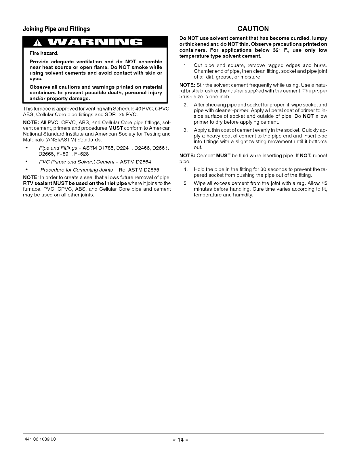
Joining Pipeand Fittings
Fire hazard.
Provide adequate ventilation and do NOT assemble
near heat source or open flame. Do NOT smoke while
using solvent cements and avoid contact with skin or
eyes.
Observe all cautions and warnings printed on material
containers to prevent possible death, personal injury
and/or property damage.
This furnace is approved for venting with Schedule 40 PVC, CPVC,
ABS, Cellular Core pipe fittings and SDR-26 PVC.
NOTE: All PVC, CPVC, ABS, and Cellular Core pipe fittings, sol-
vent cement, primers and procedures MUST conform to American
National Standard Institute and American Society for Testing and
Materials (ANSl/ASTM) standards.
• Pipe and Fittings - ASTM D1785, D2241, D2466, D2661,
D2665, F-891, F-628
• PVC Primer and Solvent Cement - ASTM D2564
• Procedure for Cementing Joints - Ref ASTM D2855
NOTE: In order to create a seal that allows future removal of pipe,
RTV sealant MUST be used on the inlet pipe where it joins to the
furnace. PVC, CPVC, ABS, and Cellular Core pipe and cement
may be used on all other joints.
CAUTION
Do NOT use solvent cement that has become curdled, lumpy
or thickened and do NOT thin. Observe precautions printed on
containers. For applications below 32 ° F., use only low
temperature type solvent cement.
1. Cut pipe end square, remove ragged edges and burrs.
Chamfer end of pipe, then clean fitting, socket and pipe joint
of all dirt, grease, or moisture.
NOTE: Stir the solvent cement frequently while using. Use a natu-
ral bristle brush orthe dauber supplied with the cement. The proper
brush size is one inch.
2. After checking pipe and socket for proper fit, wipe socket and
pipe with cleaner-primer. Apply a liberal coat of primer to in-
side surface of socket and outside of pipe. Do NOT allow
primer to dry before applying cement.
3. Apply a thin coat of cement evenly in the socket. Quickly ap-
ply a heavy coat of cement to the pipe end and insert pipe
into fittings with a slight twisting movement until it bottoms
out.
NOTE: Cement MUST be fluid while inserting pipe. If NOT, recoat
pipe.
4. Hold the pipe in the fitting for 30 seconds to prevent the ta-
pered socket from pushing the pipe out of the fitting.
5. Wipe all excess cement from the joint with a rag. Allow 15
minutes before handling. Cure time varies according to fit,
temperature and humidity.
441 06 1039 oo - 14 -
 Loading...