

ICP C9MPD050F12B1, C9MPD075F12A1, C9MPD075F12B1, C9MPD080J16A2, C9MPD080J16B1 Installation Guide
...Page 1
INSTALLATION INSTRUCTIONS
For Vent Drain Kit NAHAOOIDK
used on N9MP1, N9MP2, *9MPD, *9MPT & *9MPV Multi Position Gas Furnaces.
Denotes Brand (T, H or C)
Please read these instructions completely before attempting installation.
Parts List for Plastic Bag
Description
Coupling, Discharge
Clamp, Hose
Gasket, Trap
SMS, #8 X 1/2" Conical
Clamp, 5/8" ID
Clamp, 3/4" ID
Yellow or Black Cap (for #1014003) 1170893
USE THE PARTS IN THIS KIT. EQUIVALENT PARTS IN THE
FURNACE MAY BE DISCARDED.
These instructions are a supplement to the Installation Instructions shipped with each furnace. Refer to these instructions
for details on vent pipe sizing, maximum vent lengths, assembling the vent system and starting up the furnace.
Part# Qty.
1002522 1 Description Part# Qty.
1013830 2 Plastic, Bag 1013402 1
1013701 1 Tube, Rubber 3/16" ID 1009238 1
1012537 2 Drain Tee 1171915 1
1012975 2 Drain Tee Trap 1171916 1
1012976 2 Trap, Condensate 1171917 1
2 Timprene Drain Hose 1/2" ID 1014358 1
Timprene Drain Hose 518" ID 1014359 1
Instructions, Drain Kit 441 06 1043 O0 1
Drain, Vent 1014003 1
Parts List for Carton
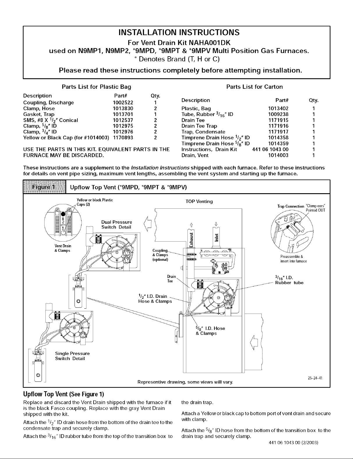
Upflow Top Vent (*9MPD, *9MPT & *9MPV)
Yellow or black Plastic
aps(Z)
Dual Pressure
_ Switch Detail _ _
VentDrain _ // _ I
(optional) E
F _:_q Drain
/ Tee\
TOP Venting
Trap Connection "Clamp ears"
Preassemble &
insert into furnace
3/16" I,D.
Rubber tube
Pointed OUT
L_ _ Hose& Clamps_
_1 SiwnigtI& PrDeetaS_lre
Representive drawing, some views will vary,
UpflowTopVent (See Figure 1)
Replace and discard the Vent Drain shipped with the furnace if it
is the black Fasco coupling. Replace with the gray Vent Drain
shipped with the kit.
Attach the 1/2" ID drain hose from the bottom of the drain tee to the
condensate trap and securely clamp.
Attach the 3/16" ID rubber tube from the top of the transition box to
& Clamps
25-24-41
the drain trap.
Attach a Yellow or black cap to bottom port of vent drain and secure
with clamp.
Attach the 5/8" ID hose from the bottom of the transition box to the
drain trap and securely clamp.
441 06 1043 O0 (2/2003)
Page 2
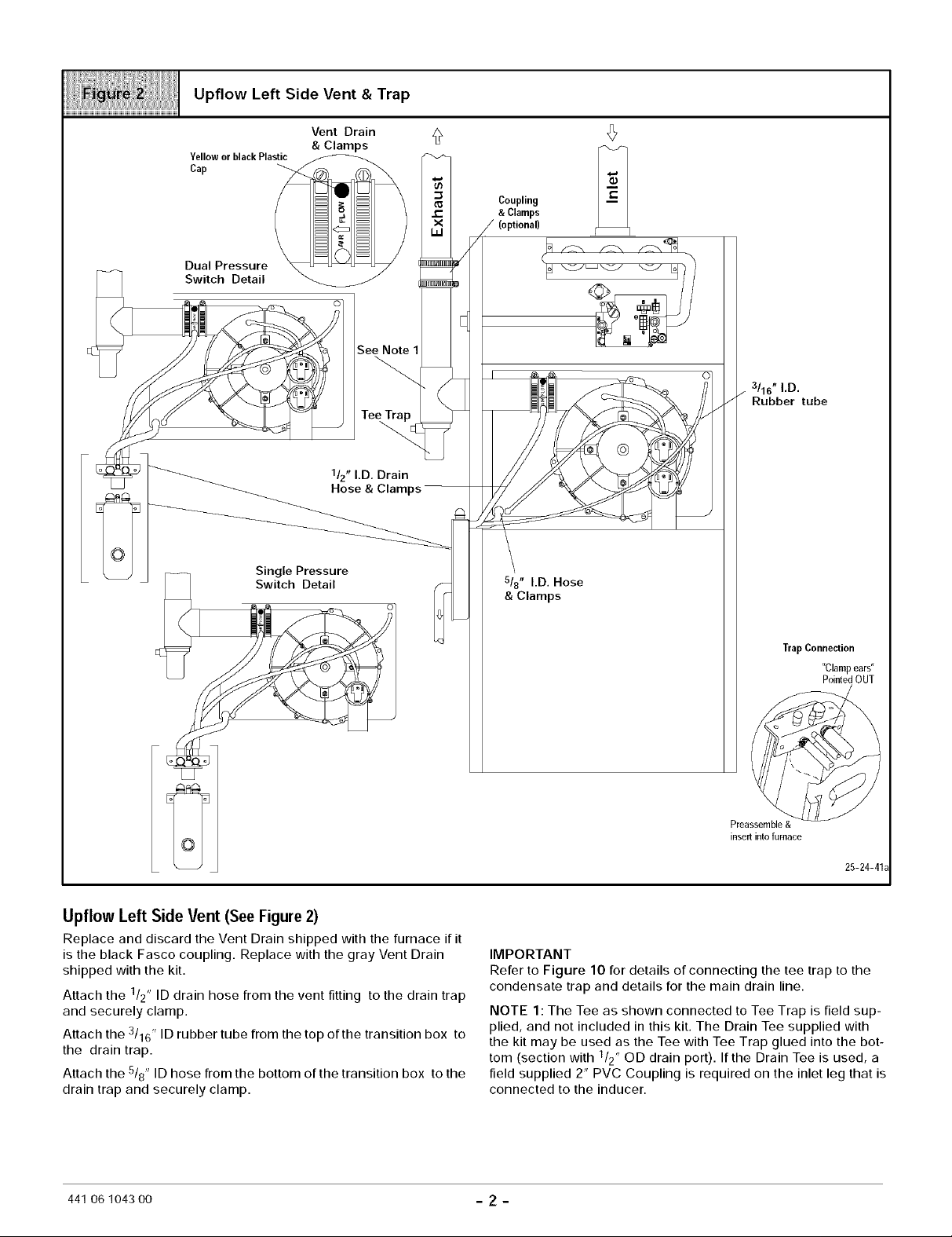
Upflow Left Side Vent & Trap
Vent Drain
YelloworblackPlastic _
Cap _ _'_'_
Dual Pressure
Switch Detail
& Clamps
See
,ee
1/2" LD, Drain
Hose & Clamps --
Coupling
&Clamps
j (optional)
3/16" I.D.
Rubber tube
Single Pressure
Switch Detail
Upflow Left Side Vent (See Figure 2)
Replace and discard the Vent Drain shipped with the furnace if it
is the black Fasco coupling. Replace with the gray Vent Drain
shipped with the kit.
Attach the 1/2" ID drain hose from the vent fitting to the drain trap
and securely clamp.
Attach the 3/16" ID rubber tube from the top of the transition box to
the drain trap.
Attach the 5/8" ID hose from the bottom of the transition box to the
drain trap and securely clamp.
Trap Connection
"Clamp ears"
Pointed OUT
Preassemble &
insert into furnace
25-24-41_
IMPORTANT
Refer to Figure 10 for details of connecting the tee trap to the
condensate trap and details for the main drain line.
NOTE 1 : The Tee as shown connected to Tee Trap is field sup-
plied, and not included in this kit. The Drain Tee supplied with
the kit may be used as the Tee with Tee Trap glued into the bot-
tom (section with 1/2" OD drain port). If the Drain Tee is used, a
field supplied 2" PVC Coupling is required on the inlet leg that is
connected to the inducer.
441 06104300 - 2 -
Page 3
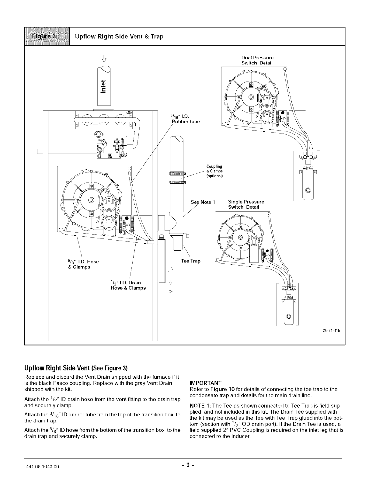
Upflow Right Side Vent & Trap
(}
3/16" I,D.
Rubber tube
Dual Pressure
Switch Detail
Coupling
(optional)
See Note 1 Single Pressure
Switch Detail
518" I,D. Hose
& Clamps
112"I.D, Drain
Hose & Clamps
Upflow Right Side Vent (See Figure 3)
Replace and discard the Vent Drain shipped with the furnace if it
is the black Fasco coupling. Replace with the gray Vent Drain
shipped with the kit.
Attach the 1/2" ID drain hose from the vent fitting to the drain trap
and securely clamp.
Attach the 3/16" ID rubber tube from the top of the transition box to
the drain trap.
Attach the 5/8" ID hose from the bottom of the transition box to the
drain trap and securely clamp.
\
Tee Trap
25-24-41b
IMPORTANT
Refer to Figure 10 for details of connecting the tee trap to the
condensate trap and details for the main drain line.
NOTE 1 : The Tee as shown connected to Tee Trap is field sup-
plied, and not included in this kit. The Drain Tee supplied with
the kit may be used as the Tee with Tee Trap glued into the bot-
tom (section with 1/2" OD drain port). If the Drain Tee is used, a
field supplied 2" PVC Coupling is required on the inlet leg that is
connected to the inducer.
441 06 1043 OO 3
Page 4

Downflow Left Side Vent & Trap
Dual Pressure
Switch Detail
Coupling
/ & Clamps
(optional)
3/16" I.D, Rubber tube
llz" I.D. Drain
Hose & Clamps
Downflow Left Side Vent (See Figure4)
Replace and discard the Vent Drain shipped with the furnace if it
is the black Fasco coupling. Replace with the gray Vent Drain
shipped with the kit.
Attach the 1/2" ID drain hose from the vent fitting to the drain trap
and securely clamp.
Attach the 3/16" ID rubber tube from the top of the transition box to
the drain trap.
Attach the 5/8" ID hose from the bottom of the transition box to the
drain trap and securely clamp.
518" I.D. Hose
& Clamps
25-24-45
IMPORTANT
Refer to Figure 10 for details of connecting the tee trap to the
condensate trap and details for the main drain line.
NOTE 1 : The Tee as shown connected to Tee Trap is field sup-
plied, and not included in this kit. The Drain Tee supplied with
the kit may be used as the Tee with Tee Trap glued into the bot-
tom (section with 1/2" OD drain port). If the Drain Tee is used, a
field supplied 2" PVC Coupling is required on the inlet leg that is
connected to the inducer.
441 06 1043 O0 - 4 -
Page 5

Downflow Right Side Vent & Trap
3/16" I.D. Rubber tube
5/8" I,D. Hose 112"I.D. Drain
& Cla_ie & Clamps
Downflow Right Side Vent (See Figure 5)
Replace and discard the Vent Drain shipped with the furnace if it
is the black Fasco coupling. Replace with the gray Vent Drain
shipped with the kit.
Attach the 1/2" ID drain hose from the vent fitting to the drain trap
and securely clamp.
Attach the 3/16" ID rubber tube from the top of the transition box to
the drain trap.
Attach the 5/8" ID hose from the bottom of the transition box to the
drain trap and securely clamp.
Trap Connection "Clamp ears"
Pointed OUT
Preassemble&
insertimofurnace
25-24-46
IMPORTANT
Refer to Figure 10 for details of connecting the tee trap to the
condensate trap and details for the main drain line.
NOTE 1 : The Tee as shown connected to Tee Trap is field sup-
plied, and not included in this kit. The Drain Tee supplied with
the kit may be used as the Tee with Tee Trap glued into the bot-
tom (section with 1/2" OD drain port). If the Drain Tee is used, a
field supplied 2" PVC Coupling is required on the inlet leg that is
connected to the inducer.
441 06 1043 O0 5
Page 6

Horizontal Left-Thru Top
3/16" I.D,
Rubber tube
Coupling
& Clamps
(optional)
Single Pressure
Switch Detail
Note 1
E_
Alternate Orientation
Yellow or
black Cap
& Clamp
llz" I,D. Drain
Hose & Clamps
Horizontal Left-Thru Top(See Figure 6)
Replace and discard the Vent Drain shipped with the furnace if it
is the black Fasco coupling. Replace with the gray Vent Drain
shipped with the kit.
Attach the 1/2" ID drain hose from the vent fitting to the drain trap
and securely clamp.
Attach the 3/16" ID rubber tube from the top of the transition box to
the drain trap.
Attach the 5/8" ID hose from the bottom of the transition box to the
drain trap and securely clamp.
Attach a Yellow or black ca p to bottom port of vent drain and secure
518" I.D. Hose
)s
TrapConnection
"Clamp ears"
Pointed OUT
Preassemble &
insert into furnace
25-24-47
with clamp.
IMPORTANT
Refer to Figure 10 for details of connecting the tee trap to the
condensate trap and details for the main drain line.
NOTE 1 : The Tee as shown connected to Tee Trap is field sup-
plied, and not included in this kit. The Drain Tee supplied with
the kit may be used as the Tee with Tee Trap glued into the bot-
tom (section with 1/2" OD drain port). If the Drain Tee is used, a
field supplied 2" PVC Coupling is required on the inlet leg that is
connected to the inducer.
441 06104300 - 6 -
Page 7

TeeTrap
Horizontal Left Side Vent
See Note 1
Sin le Pressure
Switch Detail
]
tr
Hose & Clamps
Alternate Orientation
L_
3/16" I.D, Rubber tube
Horizontal Left Side Vent (SeeFigure 7)
Replace and discard the Vent Drain shipped with the furnace if it
is the black Fasco coupling. Replace with the gray Vent Drain
shipped with the kit.
Attach the 1/2" ID drain hose from the vent fitting to the drain trap
and securely clamp.
Attach the 3/16" ID rubber tube from the top of the transition box to
the drain trap.
Attach the 5/8" ID hose from the bottom of the transition box to the
drain trap and securely clamp.
\
\
5/8" I.D. Hose
& Clamps
Preassemble& 25-24-48
insertinto furnace
IMPORTANT
Refer to Figure 10 for details of connecting the tee trap to the
condensate trap and details for the main drain line.
NOTE 1 : The Tee as shown connected to Tee Trap is field sup-
plied, and not included in this kit. The Drain Tee supplied with
the kit may be used as the Tee with Tee Trap glued into the bot-
tom (section with 1/2" OD drain port). If the Drain Tee is used, a
field supplied 2" PVC Coupling is required on the inlet leg that is
connected to the inducer.
Trap Connection
"Clamp ears"
Pointed OUT
441 06 1043 O0 7
Page 8

Horizontal Right-Thru Top
Single Pressure
Switch Detail
Alternate Orientation
3/16" I,D. Rubber tube
Yellow or
1/2" I,D. Drain black Cap
Hose & Clamps &
I I
G
I.D, Hose Trap Connection
Coupling
& Clamps
[optional)
oLo
[
See Note
Tee Trap
o
& Clamps
"Clampears"
PointedOUT
Horizontal Right- Thru Top(See Figure 8)
Replace and discard the Vent Drain shipped with the furnace if it
is the black Fasco coupling. Replace with the gray Vent Drain
shipped with the kit.
Attach the 1/2" ID drain hose from the vent fitting to the drain trap
and securely clamp.
Attach the 3/16" ID rubber tube from the top of the transition box to
the drain trap.
Attach the 5/8" ID hose from the bottom of the transition box to the
drain trap and securely clamp.
Plug the end of the drain tee with a Yellow or black cap and fasten
with a clamp.
441 06 1043 O0 - 8 -
Preassemble &
insert into furnace 25-24-49
Attach a yellow cap to bottom port of vent drain and secure with
clamp.
IMPORTANT
Refer to Figure 10 for details of connecting the tee trap to the
condensate trap and details for the main drain line.
NOTE 1 : The Tee as shown connected to Tee Trap is field sup-
plied, and not included in this kit. The Drain Tee supplied with
the kit may be used as the Tee with Tee Trap glued into the bot-
tom (section with 1/2" OD drain port). If the Drain Tee is used, a
field supplied 2" PVC Coupling is required on the inlet leg that is
connected to the inducer.
Page 9

Horizontal Right-Side Vent
Single Pressure
Switch Detail
3/16" I.D. Rubber tube _"
11z"I,D. Drain
Hose & Clamps
Couplings.
& Clamps_.
_ee Note
T
2
_HnHnlfl_E
_HnHnlfl_C
E
Tee Trap
C
Horizontal Right- Side Vent (See Figure 9)
Replace and discard the Vent Drain shipped with the furnace if it
is the black Fasco coupling. Replace with the gray Vent Drain
shipped with the kit.
Attach the 1/2" ID drain hose from the vent fitting to the drain trap
and securely clamp.
Attach the 3/16" ID rubber tube from the top of the transition box to
the drain trap.
Attach the 5/8" ID hose from the bottom of the transition box to the
drain trap and securely clamp.
441 06 1043 O0 - 9 -
\
\
518" I.D, Hose
& Clamps
IMPORTANT
Refer to Figure 10 for details of connecting the tee trap to the
condensate trap and details for the main drain line.
NOTE 1 : The Tee as shown connected to Tee Trap is field sup-
plied, and not included in this kit. The Drain Tee supplied with
the kit may be used as the Tee with Tee Trap glued into the bot-
tom (section with 1/2" OD drain port). If the Drain Tee is used, a
field supplied 2" PVC Coupling is required on the inlet leg that is
connected to the inducer.
TrapConnection
"Clamp ears"
Pointed OUT
Preassemble &
insert into furnace 25-24-50
Page 10

Connecting Tee Trap to Condensate Trap and Main Drain Line
Open Tee
\
Evaporator Coil
Drain Line
Main Drain Line
b_
The Tee Trap must be connected to the main condensate drain
line as conceptually shown above. Different installations may
require slightly different orientations. The following steps apply to
all installations,
1. TheTeeTrapshouldbeinstalledasclosetothesideortopof
the furnace as practical. Minimize the distance between the
inducer and the Tee Trap as much as possible.
2. An open tee is to be used at the Tee Trap discharge. The top
end of the tee should be open to the atmosphere to eliminate
potential air lock problems.
25-24-41T
3. The drain line from the Tee Trap is to be connected to the fur-
nace condensate trap drain line as shown above.
4. Condensate drain lines from a cooling coil must be con-
nected downstream of the connection point of the Tee Trap
and Furnace Condensate Trap.
Important: Prime both traps with water before operation.
Failure to prime the traps may result in discharge of flue gases
from the condensate drain line and open tee for a period of time,
and may result in temporary lockout of the furnace upon start up.
441 06104300 - 10 -
 Loading...