

Page 1
Condensing Gas Furnaces
90+ Four Position Furnaces
N9MP1, N9MP2, *9MPD, *9MPT & *9MPV
Non-Condensing Gas Furnaces
80+ Four Position Furnaces
N8MPN/L, *8MPN/L, *8MPT & *8MPV
*8DNL (Downflow only)
FIRE OR EXPLOSION HAZARD.
Failure to follow safety warnings
exactly could result in death, serious
injury and/or property damage.
--Do not store or use gasoline or
other flammable vapors and liquids
in the vicinity of this or any other
appliance.
-- WHAT TO DO IF YOU SMELL GAS
* Do NOT try to light any appliance.
* Do NOT touch any electrical
switch; do NOT use any phone in
your building.
* Leave the building immediately
* Immediately call your gas supplier
from a neighbor's phone. Follow
the gas supplier's instructions.
* If you cannot reach your gas
supplier, call the fire department.
--Installation and service must be
performed by a qualified installer,
service agency or the gas supplier.
Installer: Affix these instructions
on or adjacent to the furnace.
User: Please read all instructions
in the manual and retain these
instructions for future reference.
International Comfort Products, LLC
Lewisburg, TN 37091
PrintedinU.S.A. (01/01/2006) 441 02 2011 01
Page 2
User's Information Manual
Contents
Danger, Warning and Caution ................ 2
Safety Rules ............................. 3
Combustion Air (Your Safety) ................ 4
Indoor Humidity (Your Comfort) .............. 5
About Your Furnace ....................... 5
Operating Your Furnace .................... 7
Furnace Maintenance ...................... 8
Warranty ............................... 11
Danger,Warningand Caution
Recognize safety information.
/%
This is the safety-alert symbol/'x . When you see this symbol on
the furnace and in instruction manuals be alert to the potential for
personal injury.
Understand the signal words DANGER, WARNING and CAU-
TION. These words are used to identify levels of hazard serious-
ness. The signal word DANGER is only used on product labels to
signify an immediate hazard. The signal words WARNING and
CAUTION will be used on product labels and throughout this manu-
al and other manuals that may apply to the product.
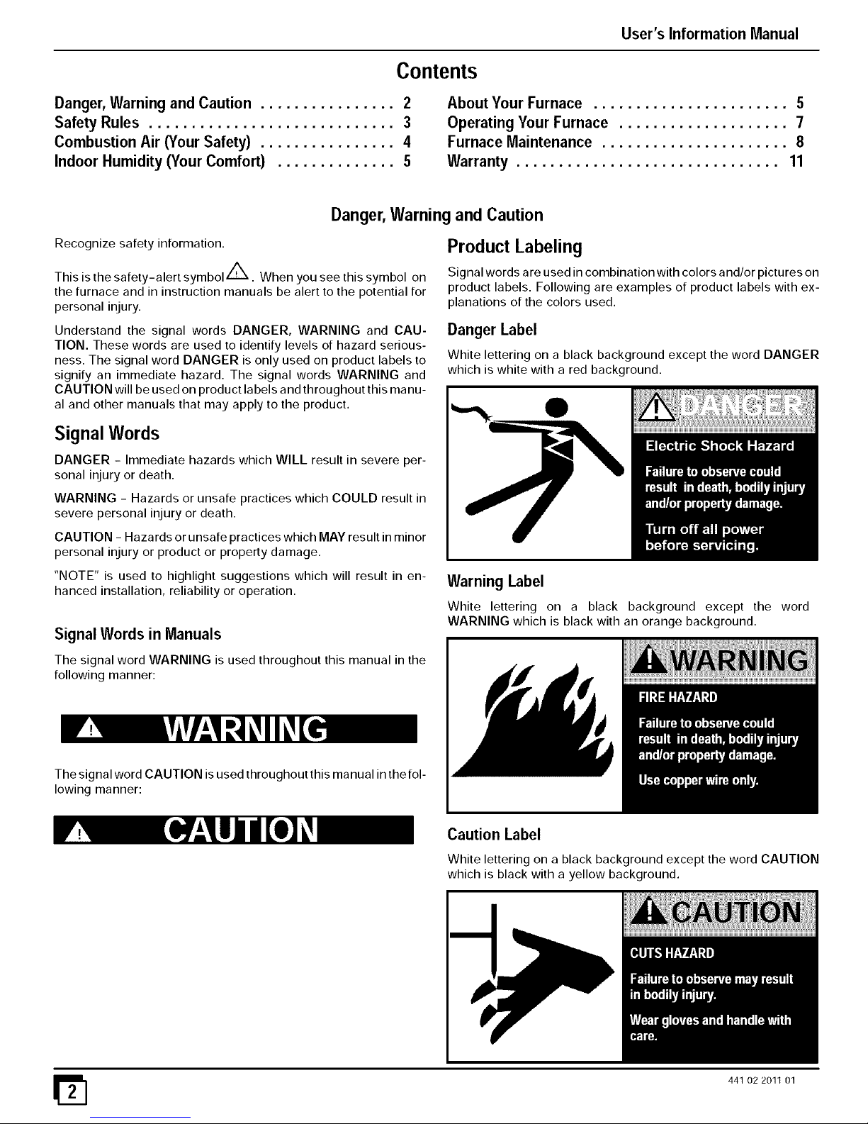
Product Labeling
Signal words are used in combination with colors and/or pictures on
product labels. Following are examples of product labels with ex-
planations of the colors used.
Danger Label
White lettering on a black background except the word DANGER
which is white with a red background.
Signal Words
DANGER - Immediate hazards which WILL result in severe per-
sonal injury or death.
WARNING - Hazards or unsafe practices which COULD result in
severe personal injury or death.
CAUTION - Hazards or unsafe practices which MAY result in minor
personal injury or product or property damage.
"NOTE" is used to highlight suggestions which will result in en-
hanced installation, reliability or operation.
Signal Words in Manuals
The signal word WARNING is used throughout this manual in the
following manner:
Warning Label
White lettering on a black background except the word
WARNING which is black with an orange background.
The signal word CAUTION is used throughout this manual in the fol-
lowing manner:
Caution Label
White lettering on a black background except the word CAUTION
which is black with a yellow background.
441 02 2011 01
Page 3

User's Information Manual
DEATH, PERSONAL INJURY AND/OR PROPERTY
DAMAGE HAZARD
Failure to observe and follow Cautions, Warnings
and instructions could result in death, personal
injury or property damage.
Read this manual and follow its instructions and
adhere to all Cautions and Warnings in the manual
and on the furnace.
Consult a qualified service agency for
installation, adjustment and maintenance.
SafetyRules
Your furnace is built to provide many years of safe and dependable
service providing it is properly installed and maintained. Howev-
er, abuse and/or improper use can shorten the life of the furnace and
create hazards for you, the owner.
A. The U.S. Consumer Product Safety Commission recom-
mends that users of gas-burning appliances install car-
bon monoxide detectors. There can be various sources
of carbon monoxide in a building or dwelling. The
sources could be gas-fired clothes dryers, gas cooking
stoves, water heaters, furnaces, gas-fired fireplaces,
wood fireplaces, and several other items. Carbon mon-
oxide can cause serious bodily injury and/or death. Car-
bon monoxide or "CO" is a colorless and odorless gas
produced when fuel is not burned completely or when
the flame does not receive sufficient oxygen.
Therefore, to help alert people of potentially dangerous
carbon monoxide levels, you should have carbon mon-
oxide detectors that are listed as complying with a stan-
dard by a nationally recognized agency (e.g. ANSI/UL
2034-2002, CSA 6.19-01, or International Approval Ser-
vices 6-96) installed and maintained in the building or
dwelling (see Note below).
B. There can be numerous sources of fire or smoke in a building
or dwelling. Fire or smoke can cause serious bodily injury,
death, and/or property damage. Therefore, in order to alert
people of potentially dangerous fire or smoke, you should
have fire and smoke detectors that are listed by Underwriters
Laboratories installed and maintained in the building or
dwelling (see Note below).
Note: The manufacturer of your furnace does not test any detec-
tors and makes no representations regarding any brand or
type of detector.
C. To ensure safe and efficient operation of your furnace, you
should do the following:
1. Thoroughly read this manual and labels on the furnace.
This will help you understand how your furnace operates and
the hazards involved with gas and electricity.
2. The furnace area must be kept clear and free of combus-
tible materials, gasoline, and other flammable vapors
and liquids.
3. Do not use this furnace if any part has been underwater.
A flood-damaged furnace is extremely dangerous. At-
tempts to use the furnace can result in fire or explosion.
Immediately call a qualified service agency to inspect
the furnace and to replace all control system parts, elec-
trical parts, and gas controls which have been wet or the
4.
5.
6.
Never block or obstruct the openings on the furnace, or
any ducts that provide air to the furnace. Air must be pro-
vided for proper and safe operation of the furnace for com-
bustion and ventilation of flue gases. See the" Combustion
Air (Your Safety) section of this manual.
Familiarize yourself with the possible air starvation sig-
nals. Check the combustion air supply. Some models use
air drawn from outdoors, See Figure 3. Other models and
other appliances use combustion air from inside the struc-
ture. Air starvation signals are given in the following "Com-
bustionAir(YourSafety)', section of this manual. Ifany of the
signals are noticed, perform a combustion air check as
shown in the following CombustionAir Checks section of this
manual or call a qualified service agency. If you add weather
stripping, storm windows, insulation, an additional fuel burn-
ing appliance, or remodel the structure, a combustion air
check MUST be accomplished after the addition
Maintain safety and service clearances from the furnace.
These clearances are listed on the furnace rating plate. Keep
the furnace area clean and free of combustible materials at
all times. Never store gasoline, paint, aerosol cans, waxes,
bleaches, dry cleaning fluid or items such as paper or rags
near the furnace.
7. Examine the furnace area when the furnace or additional
insulation is added since some insulation materials may
be combustible. Furnace must be kept free and clear of ex-
posed or loose insulation materials in the area of installation.
8.Should the gas supply fail to shut off or if overheating oc-
curs, shut off the gas valve to the furnace before shut-
ting offthe electrical supply. Read the label on the front of
the furnace and the Operating Your Furnace section of this
manual for steps to turn off the furnace.
9.Familiarize yourself with all controls. Make sure you know
how to shut off the gas and the electrical power to the fur-
nace. Read the label on the front of the furnace and the Oper-
ating Your Furnace section of this manual for steps to start
and turn off the furnace. If the furnace is to be shut down for
an extended length of time (example; remodeling project),
turn off both the gas and the electrical power. For safety, al-
ways turn them off before performing service or maintenance
on the furnace.
10. Establish a regular service and maintenance schedule.
This will ensure efficient and safe operation of the furnace. It
is recommended that you have a qualified service agency
perform a complete check on the furnace before each heat-
ing season. See furnace QualifiedAgencyChecksandCom-
bus#on Air Checks section of this manual.
11. Monthly Inspection. A properly adjusted gas furnace
should not require cleaning at frequent intervals, but it should
be inspected regularly to ensure safe and efficient operation.
A brief monthly inspection is recommended that does not re-
quire disassembly. Examine the furnace installation to deter-
mine that:
a. Check the return air duct connection. The duct connection
must be physically sound, sealed to the furnace casing
and must terminate outside the space containing the fur-
nace.
b. All flue gas carrying areas external to the furnace (i.e.
chimney, vent connector) are clear and free of obstruc-
tions.
c. The vent connector is in place, slopes upward and is
furnace, if deemed necessar . h sicall sound without holes or excessive corrosion.
441 02 2011 01 iII
131
Page 4

User's Information Manual
d. (Upflow or downflow installations with duct connection at
bottom only.) The physical support of the furnace is sound
without sagging, cracks, gaps, etc., around the base so as
to provide an air seal between the support and the base.
e. There should be no obvious signs of deterioration of the
furnace.
f. Check that the burner flames are in good adjustment. To
inspect the Main Burner flames it will be necessary to re-
move the Iouvered door on the front of the furnace, except
for furnaces not having any louvers in the doors. The
doors (no louvers) of these furnaces must remain installed
(to prevent changes in flame appearance) while inspect-
ing the Main Burner flames through the view port in the
door. Contact a qualified service agency at once if an
abnormal flame appearance is identified.
Main Burner Flame: Check for the following:
• Stable and blue flames. See Figure 1.
• Flames extending directly from burner into heat
exchanger.
• Flames do NOT touch sides of heat exchanger.
NOTE: Dust may cause orange tips or wisps of yellow, but flames
MUST NOT have solid, yellow tips.
Main Burner
10-10-78
• Check main burner flames monthly.
g. With the equipment shutoff valve turned OFF, remove the
burner compartment door of the furnace to use a flashlight
to inspect the visible parts of the burners and igniter.
Check for loose soot and give particular attention to ob-
vious deterioration from corrosion or other sources. If soot
or deterioration is found inside the furnace, DO NOT OP-
ERATE FURNACE; call a qualified service agency.
h. Inspect the drain line and overflow line monthly (condens-
ing furnace and/or air conditioning cooling coil attached to
furnace).
Combustion Air (Your Safety)
New materials and methods are being used in construction and re-
modeling which result in lower energy costs for heating and cooling.
It may also mean your appliances may not be getting enough air for
combustion and ventilation of flue gases. The use of exhaust fans,
fireplaces, clothes dryers, and other appliances consume air or vent
it to the outdoors.
If the gas appliances or heating furnace can't get enough air, two
conditions may result:
1. The appliances or furnace may produce carbon monoxide
gas.
2. The appliance may not vent flue gases properly. The follow-
ing are signs that your appliances may not be getting enough
air for proper combustion.
Be aware of these signals;
1. Headaches-Nausea-Dizziness
2. Excessive humidity-heavily frosted windows or a moist
"clammy" feeling in the structure.
3. Smoke from the fireplace won't draw up the
chimney.
CARBON MONOXIDE POISONING HAZARD.
Carbon monoxide poisoning could result in death
from asphyxiation or serious personal injury.
If you experience headaches, nausea, or
dizziness, carbon monoxide may be present.
Leave the house immediately and call your gas
supplier.
Combustion Air Checks
If any of the above signals are noticed, perform a combustion air
check or call a qualified service agency. If you add weather strip-
ping, storm windows, insulation, an additional fuel burning ap-
pliance, or remodel the structure, a combustion air check MUST be
accomplished after the addition.
Make the inspection as follows:
1. Close all doors and windows. If you have a fireplace, start a
fire and wait until flames are burning vigorously.
2. Turn on all exhausting devices, such as: kitchen and bath-
room exhaust fans and dryers (gas or electric).
3. Turn on all vented gas appliances, such as: heating equip-
ment (includes any room heaters) and water heaters.
4. Wait ten (10) minutes for drafts to stabilize.
5. On appliances with a draft hood, check for spillage by holding
a lighted match 2" from the draft hood opening. Reference
Figure 2, which shows a water heater draft hood.
CARBON MONOXIDE POISONING HAZARD
Lack of combustion air could result in carbon
monoxide gas which could cause death or serious
personal injury.
All fuel-burning appliances must be provided with
enough fresh air for proper combustion and
ventilation of flue gases.
Some models use air from the space in which they
are located, and other appliances in the same space
may also be using indoor air for ventilation and/or
combustion.
Water Heater Draft Hood
A,
Vent Pipe _ j DraftHood
/ ",A/
I "_ Match
Match flame pulls toward draft hood.
This indicates no spillage and that appliance is getting
enough air for combustion. Return exhausting devices and
appliances to the condition in which you found them.
441 02 2011 01
Page 5

User's Information Manual
B. Match goes out or flame wavers away from draft hood, This
indicates spillage and that appliance is not getting enough air
for combustion.
CARBON MONOXIDE POISONING HAZARD.
Carbon monoxide poisoning could result in death
from asphyxiation or serious personal injury.
Draft hood spillage means there is not enough air
for proper combustion and carbon monoxide may
be present.
Keep a window open (a minimum of 2" ) near the
appliance until a permanent combustion air duct is
installed. Contact a qualified service agency.
If draft hood spillage is indicated:
1. Check for plugged vent connectors and chimneys. Repair
stoppage and test again.
2. If you have a fireplace, open a window or door near the fire-
place and then check for spillage.
If spillage stops, do not use the fireplace until you can supply
fresh air by a permanent duct.
3. If you have kitchen and bathroom exhaust fans, turn them
OFF and check for spillage.
If spillage stops, do not use exhaust fans until you can supply
fresh air by a permanent duct. Circuit breakers for fans
should be turned off and marked as to why they are off.
4. Spillage means air starvation and that an outdoor air duct or
air intake must be installed to provide air directly to the area
around the furnace. This duct or intake MU ST comply with lo-
cal and state building codes or in their absence with the Na-
tional Fuel Gas Code NFPA 54/ANSI Z223.1-2002 in the
U.S., or the National Standard of Canada, Natural Gas and
Propane Installation Code CSA B-149.1-00 in Canada.
Indoor Humidity (Your Comfort)
Relative humidity is important to your health. Proper humidification
helps cut down incidences of respiratory illness. Air that is too wet
may damage the building structure. Air that is too dry is uncomfort-
able. A quick way to test for proper humidity is as follows:
1. Look for frequent fogging or excessive condensation on the
inside of windows. This indicates the indoor humidity level is
too high for outdoor weather conditions.
2. Drop three ice cubes into a glass of water and stir. If, within
three minutes, moisture does not form on the glass, the air is
too dry and a humidifier would be beneficial. (Do not perform
this test in the kitchen, cooking vapors may produce inaccu-
rate results.)
A good relative humidity is one just high enough to barely start con-
densation along the lower edges or lower corners of the windows,
when it is cold outside. More than that can be damaging.
If the humidity is too high, try these suggestions to lower the humid-
ity:
1. Reduce setting or discontinue use of humidifier.
2. Use range and bathroom exhaust fans while cooking and
bathing. Open a door or window for a few minutes to bring in
cool drier air.
3. Cook with pans covered.
4. Take shorter baths or showers with cooler water.
441 02 2011 01
5. Install a fresh air intake duct. Cold, dryair brought in from out-
side to the furnace area lowers the indoor humidity level.
6. Have appliances checked. A malfunctioning appliance can
contribute water vapor to the structure.
7. If the problem continues, consult a heating contractor about
adding a heat recovery ventilator or air-to-air heat exchang-
er.
About Your Furnace
Figure 3 or Figure 4 shows the location of the components in the
furnace.
Circulating Air Blower
The blower circulates room air through the furnace, air ducts, and
into the rooms of the structure. The blower can be set at the thermo-
stat for automatic or manual operation. In manual mode the blower
operates continuously. In automatic, the blower does not come on
until a preset time after the gas valve is energized. When the struc-
ture reaches the temperature set on the thermostat, the furnace will
shut off. The blower will continue to run until the furnace cools down.
Thermostat
There are many types and styles of thermostats. Most thermostats
control both heating and cooling functions and have a Fan Switch
with AUTO and ON settings. On AUTO, the Circulating Air Blower
will cycle on/off with the furnace on the heating speed unless a call
for cooling is initiated. Blower speed will correspond to the mode of
operation of the furnace. If the Fan Switch is positioned to ON the
blower will run continuously.
In addition some thermostats are programmable with multiple set
backs. The set backs can be pre-programmed to lower or raise the
temperature automatically.
Be sure to become familiar with your thermostat.
Rating Plate
The rating plate contains important information for the service tech-
nician and lists the complete model, manufacturing and serial num-
bers. You should always provide all these numbers when
requesting parts or if you need service. See Figure 3, Figure 4 or
Figure 5 for rating plate location.
Door Interlock Switch
All the electrical power for the furnace goes through the door inter-
lock switch. The interlock switch interrupts electrical power to the
furnace when the blower door is removed. The furnace will not oper-
ate until the blower door is reinstalled.
Furnace Control
The furnace control provides power to the circulating air blower to
keep it on until the furnace cools down.
The fan off-delay setting can be adjusted if the fan remains on long
enough that cool drafts are felt in the room after the furnace shuts
off.
The off-delay is set by moving a set of switches (2-stage) or jumper
(1 -stage) on the control. The Wiring Diagram located on the inside
of the blower door shows the various delay combinations. Refer to
Figure 3 or Figure 4 for location of the control.
If you are unsure howto set the Off-delay Control, contact a Quali-
fied Service A enc .
Page 6

User's Information Manual
Component Locations for Four Position 90+ Furnaces
Furnace Vent Pipe (Vent Pipe Connections
through Side Panel on Some Models
Manual Equipment Shutoff
Vent Pipe Grommet
Ignitor & Flame Sensor
(not shown)
Vent Drain
Fitting
Combustion Blower
Air Intake Pipe
for Direct-Vent Furnaces)
Primary Heat Exchanger
Gas Control Valve
1/2" I.D. Vent Pipe Drain Hose
5/8" I.D, Transition Box Drain Hose --
Y
Heat Exchanger
Door Interlock Switch
Condensate Tra
Pressure Switches
(some models have one)
Diagnostic Ligl
Plastic Transition Box
Circulating Air Blower
Rating Plate
Representative drawing onh/, some models may vary in appearance.
Pressure
Switch
(Some
models
Venter
Component Locations for
80+ Furnaces (4-Position)
Heat
Exchanger
Manual
Equipment
some models ma
Circulating
Blower
Motor
\
25-24-78-1
Component Locations for
80+ Furnaces (Downflow)
Diagnostic
Manu_
Equipment
Shutoff Valve
Circulating Furnace
Control
Venter
Furnace
_Main Gas
Control Valve
Drip
Leg
Rating Plate on
inside of casing 25-24-20a-1D
Representativedrawing onh/,some models may vary in appearance.
Ignitor &
Flame
Sensor
(not shown)
Burners
441 02 2011 01
Page 7

User's Information Manual
Set the room thermostat slightly above room temperature. This will
automatically signal the furnace to start. The inducer motor will
start, and the hot surface igniter will have an orange glow. After
about 32 seconds (from the call for heat at the thermostat), the gas
valve permits gas to flow to the main burners where it is ignited.
When the flame is firmly established, the igniter shuts off. Hot
flames begin to warm the furnace's heat exchanger. After a time
delay of 30 seconds (45 seconds for low-stage on two-stage fur-
naces) the furnace blower is switched on.
NOTE: If the main burners fail to ignite, the furnace control system
will go through 3 more ignition cycles. Then, if burners fail to ignite,
the system will lockout. If lockout occurs, or the blower doesn't
come on - shut down your furnace and call a Qualified Service
Agency for service.
Pressure Switch
The furnace is equipped with one or more pressure switches to shut
down the furnace under various flue conditions. The switches are
connected to the furnace by factory supplied tubing.
OperatingYourFurnace
Keep the blower access door and all access panels in place except
for inspection or maintenance.
Before starting your furnace be sure you read and understand all of
the procedures in this manual. Check to make sure the furnace filter
is clean and correctly installed.
CARBON MONOXIDE POISONING HAZARD
Failure to provide adequate combustion and
ventilation air could result in death or
personal injury.
Provisions for combustion and ventilation air
must be provided for in accordance with
installation instructions supplied with furnace.
Starting The Furnace
See Figure 6 for an illustration of the gas control valve.
1. Turn the thermostat to its lowest temperature setting or to
OFF if equipped with a System Select Switch.
2. Turn OFF all electric power to the furnace at the disconnect
switch or circuit breaker.
Remove the burner compartment door by removing the
two(2) screws securing the door in front and lifting the door up
and outwards. Removing the door will expose the gas control
valve knob.
4. Rotate the gas control valve knob colckwise _ to OFF.
See Figure 6.
5. Wait five (5) minutes to clear out any gas. If you then smell
gas, STOP! Follow the safety information on the cover of this
manual. If you do not smell gas, go to the next step.
6. Rotate the gas control valve knob counterclockwise <_to
ON.
7. Reinstall all doors.
8. Turn ON all electrical power to the furnace.
9. Set the thermostat to the desired temperature and the Sys-
tem Select Switch to HEAT.
The furnace will activate an igniter which lights the main burners.
Turning Off The Furnace
Set the thermostat to the lowest temperature setting or set System
Select Switch to OFF, if so equipped.
Should overheating occur or the gas control valve fail to shut
off, shut off the manual equipment shutoff valve to the furnace
before shutting off the electrical supply.
Extended Shutdown
1. Set thermostat to lowest temperature setting or set thermo-
stat System Select Switch to OFF, if so equipped.
2. Turn Manual Equipment Shutoff Valve for furnace to OFF
position (at right angle or 90 ° to gas line).
3. Remove the burner compartment door by removing the two
(2) screws securing the door in front and lifting the door up
and outwards. Removing the door will expose the gas control
valve knob.
4.
5,
6.
Turn OFF electric power to the furnace at the disconnect
switch or circuit breaker. (May be left ON for set-back type
thermostat with batteries, provided thermostat has system
select switch placed in the OFF position.)
Rotate the gas control valve knob clockwise _ to OFF.
See Figure 6
Reinstall all doors.
Honeywell Gas Control Valve
Single Stage
INLET
On\Off
Knob
OUTLET
25-24-94-1
On\0ff
Knob
INLET
OUTLET
441 02 2011 01
Page 8

User's Information Manual
L P Model Furnaces
FIRE OR EXPLOSION HAZARD
Failureto detectand stop gas leak could resultin
death,personalinjuryandlorpropertydamage.
Propane gas isheavier than air. Leaking gas can
settlein low areas such as crawl space. Ifyou
suspect the presence of gas, follow the
instructionson the cover of thismanual.
If your L.E (liquefied petroleum) gas furnace is installed in an exca-
vated or low lying area, we recommend that you contact your L.E
gas supplier a bout installing a warning device that would alert you of
a gas leak.
FrozenWaterPipeHazard
Insert a funnel into the hose and pour four (4) ounces of sani-
tary type (RV) antifreeze into the condensate trap. Recon-
nect the 1/2" I.D. rubber hose to the stub on the vent drain
fitting. Secure with the hose clamp.
2. Disconnect the 5/8" I.D. rubber hose from the condensate
trap. Insert a funnel into the hose and pour four (4) ounces of
sanitary type (RV) antifreeze into the plastic transition box.
Squeeze the hose together near the end and quickly recon-
nect the 5/8" I.D. rubber hose to the stub on the condensate
trap. Secure with the hose clamp.
When you return home, your furnace will be ready to start, as it is not
necessary to drain the antifreeze from the furnace.
FurnaceMaintenance
Have your furnace inspected and serviced on an annual basis (be-
fore the heating season) by a qualified service agency.
Labeling
FROZEN AND BURST WATER PIPE HAZARD.
Failure to protect against frozen pipes may result in
burst water pipes, and/or serious property damage.
Furnace may shut down. Do not leave your home
unattended for long periods during freezing weather
without turning off water supply and draining water
pipes or otherwise protecting against the risk of
frozen pipes.
FIRE OR EXPLOSION HAZARD
Wiring errors can cause improper and dangerous
operation that could result in death, personal injury
and/or property damage.
Label all wires prior to disconnection when
servicing controls. Verify proper operation after ser-
vicing. Only qualified service agencies should
attempt electrical service.
Pressure Switches
Your furnace is designed solely to provide a safe and comfortable
living environment. The furnace is NOT designed to ensure that wa-
ter pipes will not freeze. It is equipped with several safety devices
that are designed to turn the furnace off and prevent it from restart-
ing in the event of various potentially unsafe conditions.
If your furnace remains off for an extended time, the pipes in your
home could freeze and burst, resulting in serious water damage.
If the structure will be unattended during cold weather, you should
take these precautions.
Turn off the water supply to the structure and drain the water
lines if possible and add an antifreeze for potable water to
drain traps and toilet tanks. Open faucets in appropriate
areas.
-or-
Have someone check the structure frequently during cold
weather to make sure it is warm enough to prevent pipes from
freezing. Instruct them to call a qualified service agency to
call to provide service, if required.
-or-
Install a reliable remote sensing device that will notify some-
body of freezing conditions within the home.
Winter Shutdown (90+ Furnaces)
If you go away during the winter months and do not leave the heat
on in your home, the plastic transition box and the condensate trap
on the furnace must be protected from freeze damage. (See
Figure 3)
Disconnect the 1/2" I.D. rubber hose from the vent drain fitting
(or tee) that is located downstream ofthe combustion blower.
During regular yearly maintenance, check for cracks in any
tubes on the pressure switches.
ELECTRIC SHOCK HAZARD
Failure to disconnect electricity could result in death
or personal injury.
Turn off electrical power to furnace before
performing any maintenance or removing panels or
doors.
Air Filters/Monthly
The air filter(s) should be inspected at least monthly and
cleaned or replaced as required. There are many types of filters
that are commonly used. Washable filters (constructed of alumi-
num mesh, foam, or reinforced fibers) may be cleaned by soak-
ing in mild detergent and rinsing with water. The fiberglass
disposable type should be REPLACED before it becomes
clogged. Other filter types should be serviced in accordance
with the manufacturer's recommendations.
Remember that dirty filters are the most common cause of inad-
equate heating or cooling performance.
Replacement Filters
If the filter is not located at or within the furnace, it should be located
somewhere in the return-air duct system.
The recommended sizes and types of filters that may be used with
your furnace are based on the furnace's heating gas input rate (and
cooling system capacity, if so equipped).
441 02 2011 01
Page 9

User's Information Manual
Replacement filters should be of the same type and size as the origi-
nal filters, to ensure adequate air flow and filtering. A disposable low
velocity filter can be replaced with a washable high velocity type. Do
not replace a high velocity filter with a disposable low velocity filter,
except as permitted below.
Ira cleanable (high-velocity) filter(s) is to be replaced with a dispos-
able (low-velocity) filter(s), the airflow area of the filter(s) must be
doubled (i.e., a second filter of the same size must be installed so
that only half of the air goes through each filter). A second return-air
duct to the furnace may be required in which to install the second
filter. Modification of a furnace installation shall comply with the lo-
cal installation code and the furnace installation instructions, and
shall be made only by a Qualified Service Agency.
NOTE: Some filters are marked with an arrow to indicate the
proper direction of air flowthrough the filter. The air flow direc-
tion will be towards the blower motor. Make sure filter is
installed correctly.
Filter Rack Outside Furnace
Filter Replacement - Upflow
The filter may be installed inside the bottom of the furnace blower
compartment, or the filter(s) rack may be installed under the furnace
or on either or both sides of the furnace. A plastic end cap(s) is in-
serted in the filter rack(s) after the filter(s) is installed. The end cap
keeps air from escaping around the open end of the filter rack. See
Figure 7 and Figure 8 for side and bottom locations. Rack end cap
is similar for bottom mounted filter rack.
Filter rack(s) attached to the outside of the furnace is made so the
filter simply slides out one end for removal.
Filter Replacement - Bottom Mounted Filter
Inside Furnace,
1. Turn off electric power to furnace.
2. Remove blower door.
3. Slide filter straight out toward you. See Figure 8.
4. Inspect the filter(s) and replace or clean washable types. If
filter is aluminum mesh it should be recoated with filter coat-
ing spray.
5. Replace blower door.
6. Turn on electric power to furnace.
RISK OF REDUCED FURNACE LIFE
Use of excessively dirty and/or restrictive air
filters may increase furnace operating
temperatures and shorten the life of the furnace.
Filters specified for the furnace are rated at a
maximum of 600 FPM air velocity and sized for the
furnace's airflow rate. Replacement filters must be of
equivalent type, size, and rating except as described
below.
Disposable, low-velocity filters may be used to replace
washable, high-velocity filters, providing they are sized
for 300 FPM or less.
Ifyou are uncertain of the type of replacement filter to use,
consult the furnace installer or a qualified service agency
Center Clip
side-to-side
Bottom Mounted Filter
Inside Furnace
25-24-18-1
for assistance.
Filter Replacement - Horizontal and
Downflow *8MPN/L (Not *8DNL)
Filter Replacement - Bottom or Side
Mounted Filter Rack Outside Furnace
1. Turn OFF electric power to furnace.
2. Remove the end cap from the filter rack.
3. Slide the filter out of the filter rack. See Figure 7.
4. Inspect the filter(s) and replace or clean washable types. If
filter is aluminum mesh it should be recoated with filter coat-
ing spray.
5. Reinstall the end cap in the filter rack.
6. Turn on electric power to furnace.
44102 2011 01
The filter may be installed at the inlet end of the blower compart-
ment, either inside or outside the furnace. Side inlet filter locations
are not permitted for horizontal or downflow applications.
Filter Replacement -- Downflow *8DNL
Two filters are supplied with all *8DNL downflow models. (See to
Figure 9) Refer to note for proper size. The filters are installed
through the top of the downflow furnace from the right side. To re-
move filter, refer to Figure 9 for the following steps.
NOTE: Two (2) 16" x 18" cleanable high-velocity filters are recom-
mended. A *8DNL downflow furnace with airflow up to 1200 cfm is
permitted to replace the 16" x 18" cleanable high-velocity filters
with two 16" x 18" disposable filters.
Page 10

User's Information Manual
1.
2.
3.
Turn OFF power to furnace.
Remove compartment door.
Reach up above right side of blower, and lift dirty filters out of
rack at top of furnace.
Straighten up filters and pull straight down at side of blower.
Pull out through right side of door opening.
Inspect the filter(s) and replace or clean washable types. If
filter is aluminum mesh, it should be recoated with filter coat-
ing spray.
Reinstall the filters in the filter rack.
Reinstall blower compartment door.
Turn ON electric power to the furnace.
Downflow Filter Replacement
*8DNL
6.
7.
8.
Left Side
!!!!!!!!!!!i!!!!!!!! !!!!i!!!
furnace Size
Heating Input
25-21-16a
Right Side
1000 x Btuh
50
50, 75, and 100
50, 75,100, and 125
80,100, and 125
125
150
Recommended Filter Sizes
Nominal Air Flow
Cubic Feet
per Minute (CFM)
800-900
1100-1300
1300-1500
1500-1700
1900- 2100
2300-2500
Qualified Service Agency Checks
When the furnace is being inspected for condition and operation
have the Qualified Service Agency check the following items.
1. Check all flue gas passages including main and pilot burners,
heat exchanger, and vent.
2. Check electrical wiring and connections.
External Filter Rack
A plastic end cap is inserted in the filter rack after the filter is
installed. The end cap keeps air from escaping around the open
end of the filter rack. See Figure 7 for removal of filter.
Filter racks attached to the furnace are made so the filter simply
slides out one end for removal.
1. Turn OFF electric power to furnace.
2. Remove the end cap from the filter rack.
3. Slide the filter out of the filter rack.
4. Inspect the filter(s) and replace or clean washable types. If
filter is aluminum mesh it should be recoated with filter coating
spray.
5. Reinstall the end cap in the filter rack.
6. Turn furnace on.
Internally Mounted Filter
1. Turn OFF power to furnace.
2. Remove blower door.
3. Slide filter straight out toward you. (See Figure 8.)
4. Inspect the filter(s) and replace or clean washable types. If
filter is aluminum mesh it should be recoated with filter coating
spray.
5. Replace blower door
6. Turn on electric power to furnace.
Lubrication
The blower motor and the combustion air blower are prelubricated
by the manufacturer and DO NOT require oiling.
Recommended Filter Sizes
Sq. In, Surface Area/Nominal Size (inches)
Disposable Filters
500 or 20 x 25
350 or 14 x 25 (2Req.)
400 or 16 x 18 (2Req.)
500 or 20 x 25 (2 Req.)
600 or 20 x 30 (2 Req.)
600 or 20 x 30 (2 Req.)
3.
4.
5,
Cleanable Filters
3500r 14 x 25
3500r 14 x 25
400 or 16 x 18
500 or 20 x 25
500 or 20 x 25
720 or 24 x 30
Check supply and return air ducts for leakage, blockage and
connections to furnace.
Check circulating air blower wheel and motor. Clean them if
required.
Perform an operational checkout on the furnace to be sure
safety controls function and that furnace operates properly.
For additional information, the Qualified Service Agency can
consult the installation instructions for the furnace.
441 02 2011 01
 Loading...