

ICP C8MPT050B12A1, C8MPT075F14A1, C8MPT075F14B1, C8MPT100F14A1, C8MPT100F14B1 Installation Guide
...Page 1
80+ GAS FURNACE
Category I Furnace
*8MPT Two-Stage Heating
*8MPV Variable Speed, Two-Stage Heating & Supports
Two- Stage Cooling Units * Denotes Brands (C, R, T)
See Section 5 for Category ! definition.
SAFETY CONSIDERATIONS
Improper installation, adjustment, alteration, service, maintenance, or use can cause explosion, fire, electrical shock, or
other conditions which may cause death, personal injury, or property damage. Consult a qualified installer, service agency,
or your distributor or branch for information or assistance. The qualified installer or agency must use factory-authorized kits
or accessories when modifying this product. Refer to the individual instructions packaged with the kits or accessories when
installing.
Follow att safety codes. Wear safety glasses, protective clothing, and work gloves. Use quenching cloth for brazing
operations. Have fire extinguisher available. Read these instructions thoroughly and follow all warnings or cautions
included in literature and attached to the unit. Consult local building codes, the current editions of the National Fuel Gas
Code (NFCG) NFPA 54/ANSI Z223.1, and the National Electrical Code (NEC) NFPA 70.
In Canada refer to the current editions of the National standards of Canada CAN/CSA-B149.1 and .2 Natural Gas and
Propane Installation Codes, and Canadian Electrical Code CSA C22.1.
Recognize safety information. This is the safety-alert symbol z_. When you see this symbol on the unit and in instructions
or manuals, be alert to the potential for personal injury. Understand these signal words; DANGER, WARNING, and
CAUTION. These words are used with the safety-alert symbol. DANGER identifies the most serious hazards which will
result in severe personal injury or death. WARNING signifies hazards which could result in personal injury or death.
CAUTION is used to identify unsafe practices which may result in minor personal injury or product and property damage.
NOTE is used to highlight suggestions which will result in enhanced installation, reliability, or operation.
International Comfort Products, LLC
Lewisburg, TN.37091
1.SafeInstallationRequirements.................. 4
2.Installation................................. 5
3.SideVenting................................ 8
4.Combustion&VentilationAir ................... 9
5.GasVentInstallation ......................... 12
6.HorizontalVenting ........................... 13
7.ChimneyAdapterVenting...................... 15
8.GasSupplyandPiping........................ 18
9.ElectricalWiring............................. 22
ELECTRIC SHOCK HAZARD
Failure to follow this warning
could result in personal injury
and/or death.
Turn Off All Power Before
Servicing.
Table of Contents
INSTALLER: Affix these instructions on or
adjacent to the furnace.
CONSUMER: Retain these instructions for
future reference.
10. Ductwork and Filter (Upflow/Horizontal) ......... 25
11. DuctworkandFilter(Downflow) ............... 27
12. ChecksandAdjustments .................... 30
13. FurnaceMaintenance....................... 33
14. SequenceofOperation&Diagnostic(*8MPT) ..... 34
15. WiringDiagram(*8MPT) ..................... 36
16. SequenceofOperation&Diagnostic(*8MPV) ..... 37
17. WiringDiagram(*8MPV) ..................... 39
18. ThermostatWiringGuide .................... 40
CARBON MONOXIDE POISONING AND FIRE
HAZARD.
Failure to follow this warning could result in
personal injury, death and/or property dam-
age.
This furnace is not designed for use in mobile
homes, trailers or recreational vehicles.
Portions of the text and tables are reprinted from NFPA 54 / ANSi Z223.1-2006@, with permission of National Fire Protection Association, Quincy, MA 02269 and American Gas Association
Washington DC 20001. This reprinted material is not the complete and official position of the NFPA or ANSi on the referenced subject which is represented only by the standard in its
entirety.
Specificationsare subject to changewithout notice 44101 202301 March2009
Page 2
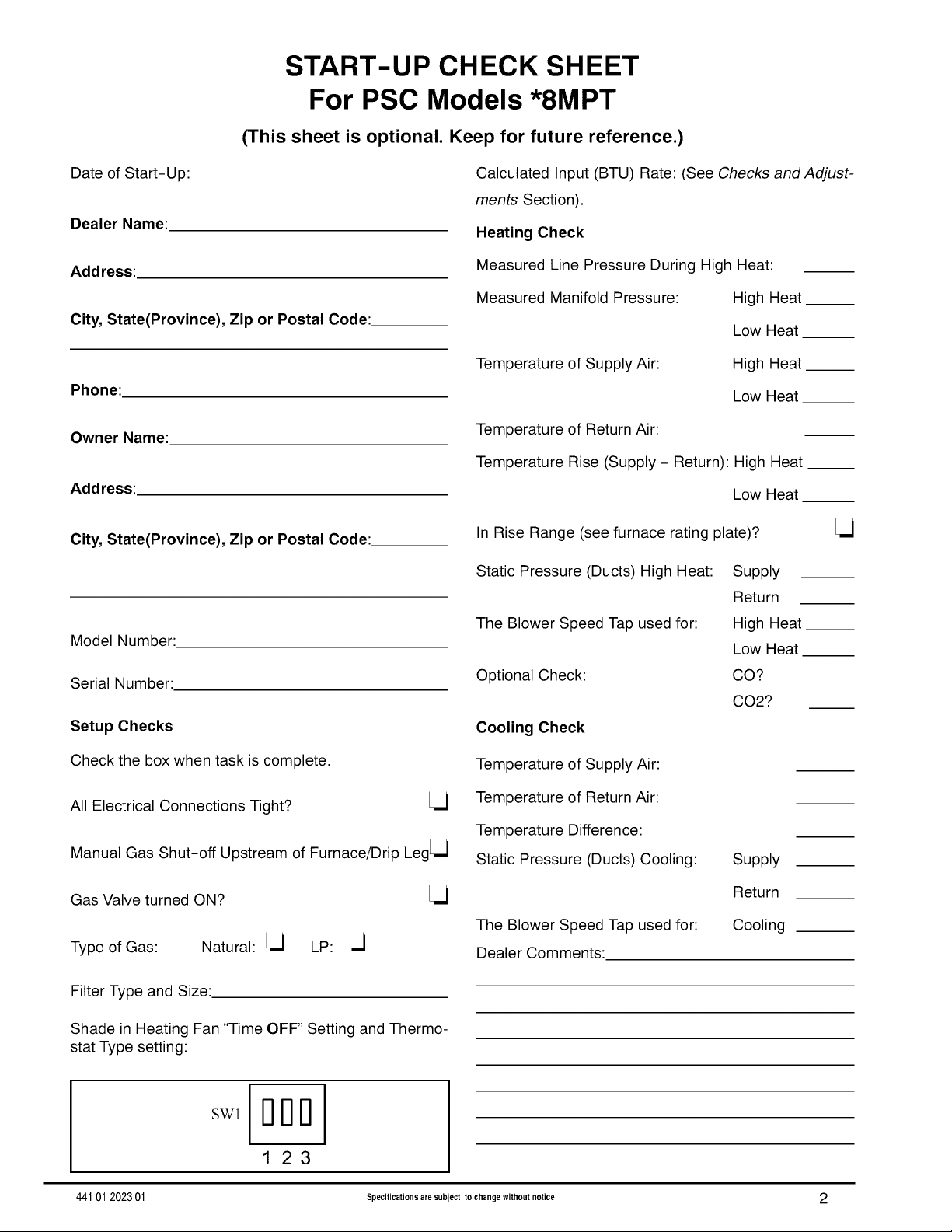
START-UP CHECK SHEET
For PSC Models *8MPT
(This sheet is optional. Keep for future reference.)
Date of Start-Up:.
Dealer Name:
Address:
City, State(Province), Zip or Postal Code:
Phone:
Owner Name:
Address:
City, State(Province), Zip or Postal Code:
Model Number:
Serial Number:
Setup Checks
Calculated Input (BTU) Rate: (See Checks and Adjust-
ments Section).
Heating Check
Measured Line Pressure During High Heat:
Measured Manifold Pressure: High Heat
Low Heat
Temperature of Supply Air:
Temperature of Return Air:
Temperature Rise (Supply - Return): High Heat __
In Rise Range (see furnace rating plate)?
Static Pressure (Ducts) High Heat:
The Blower Speed Tap used for:
Optional Check:
Cooling Check
High Heat
Low Heat
Low Heat
Supply
Return
High Heat
Low Heat
CO?
CO2?
Check the box when task is complete.
All Electrical Connections Tight? Lj
Manual Gas Shut-off Upstream of Furnace/Drip LegLU
Gas Valve turned ON? Lj
Type of Gas: Natural: Lj LP: Lj
Filter Type and Size:
Shade in Heating Fan "Time OFF" Setting and Thermo-
stat Type setting:
SWl
44101 202301 Specifications are subject to change without notice 2
Temperature of Supply Air:
Temperature of Return Air:
Temperature Difference:
Static Pressure (Ducts) Cooling:
Dealer Comments:
Supply
Return
CoolingThe Blower Speed Tap used for:
Page 3
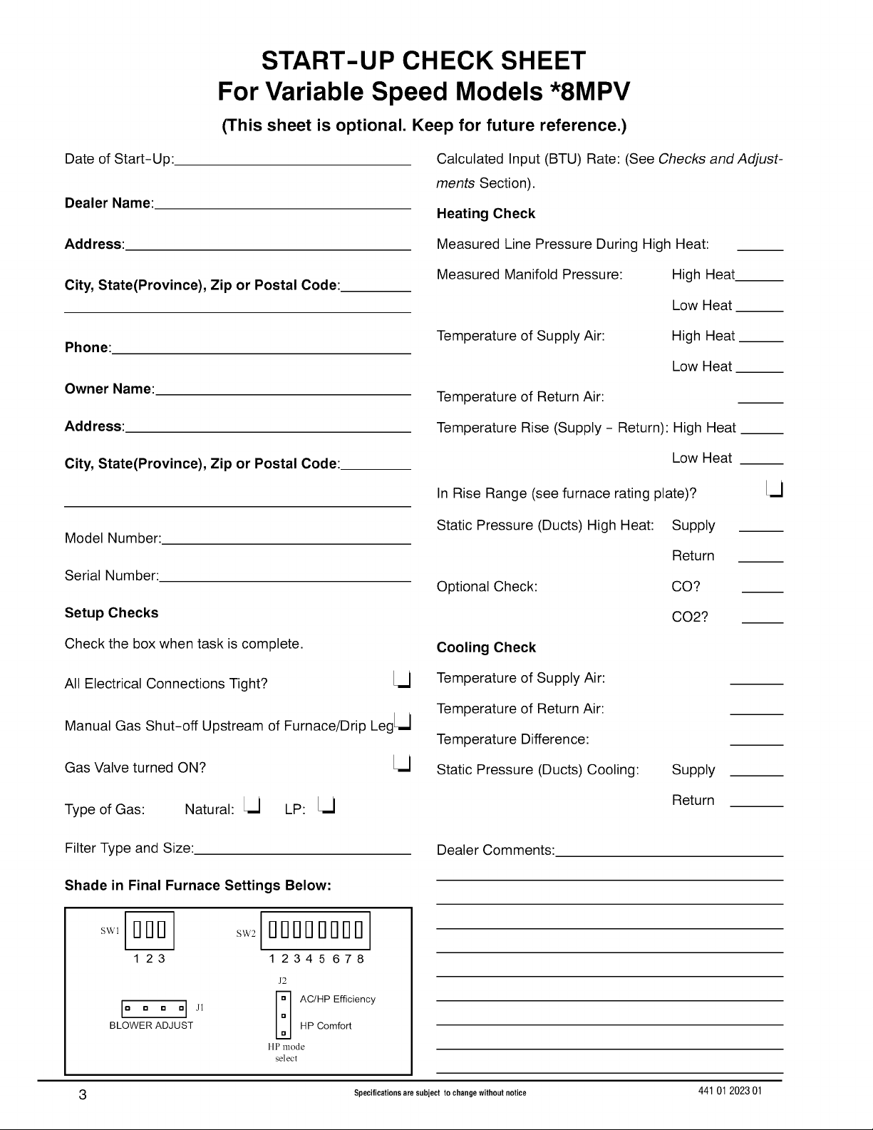
START-UP CHECK SHEET
For Variable Speed Models *8MPV
(This sheet is optional. Keep for future reference.)
Date of Start-Up:.
Dealer Name:
Address:
City, State(Province), Zip or Postal Code:
Phone:
Owner Name:
Address:
City, State(Province), Zip or Postal Code:
Model Number:
Serial Number:
Calculated Input (BTU) Rate: (See Checks and Adjust-
ments Section).
Heating Check
Measured Line Pressure During High Heat:
Measured Manifold Pressure: High Heat
Low Heat
Temperature of Supply Air:
Temperature of Return Air:
Temperature Rise (Supply - Return): High Heat __
In Rise Range (see furnace rating plate)?
Static Pressure (Ducts) High Heat: Supply
Optional Check:
High Heat
Low Heat
Low Heat
Return
CO?
Setup Checks
Check the box when task is complete.
All Electrical Connections Tight? Lj
Manual Gas Shut-off Upstream of Furnace/Drip Leg[--]
Gas Valve turned ON? Lj
Type of Gas: Natural: Lj LP: Lj
Filter Type and Size:
Shade in Final Furnace Settings Below:
SW1 [_
123
I=a D D el J; _-_ AC/HPEfficiencyBLOWER ADJUST HP Comfort
w2looooooDo1
1 234 5 678
J2
liP mode
select
Cooling Check
Temperature of Supply Air:
Temperature of Return Air:
Temperature Difference:
Static Pressure (Ducts) Cooling:
Dealer Comments:
CO2?
Supply
Return
3 Specificationsare subject to changewithout notice 44101 202301
Page 4
1. Safe Installation Requirements
Seal around supply and return air ducts.
FIRE, EXPLOSION, AND
CARBON MONOXIDE
POISONING HAZARD
Improper adjustment,
alteration, service,
maintenance or installation could result in personal
injury, death and/or property damage.
Installation or repairs made by unqualified persons
could result in hazards to you and others.
Installation MUST conform with local codes or, in
the absence of local codes, with codes of all
governmental authorities having jurisdiction.
The information contained in this manual is
intended for use by a qualified service agency that is
experienced in such work, is familiar with all
precautions and safety procedures required in such
work, and is equipped with the proper tools and test
instruments.
NOTE: This furnace is design-certified by the CSA International
(formerly AGA and CGA) for installation in the United States and
Canada. Refer to the appropriate codes, along with this manual,
for proper installation.
• Use only the Type of gas approved for this furnace (see
Rating Plate on unit). Overfiring wilt result in failure of heat
exchanger and cause dangerous operation. (Furnaces
can be converted to Propane gas with approved kit.)
• Install this furnace only in a location and position as speci-
fied in "Installation" of these instructions.
• Provide adequate combustion and ventilation air to the
furnace as specified in "Combustion and Ventilation Air" of
these instructions.
Combustion products must be discharged outdoors. Con-
nect this furnace to an approved vent system only, as spe-
cified in "Combustion and Ventilation Air, Horizontal
Venting and Chimney Adapter Venting" of these instruc-
tions.
Never test for gas leaks with an open flame. Use a com-
mercially available soap solution made specifically for the
detection of leaks to check all connections, as specified in
"Gas Supply and Piping, Final Gas Piping Check" of these
instructions.
• Always install furnace to operate within the furnace's in-
tended temperature-rise range with a duct system which
has an external static pressure within the allowable range,
as specified in "Technical Support Manual" of these in-
structions. See furnace rating plate. C.
• When a furnace is installed so that supply ducts carry air
circulated by the furnace to areas outside the space con-
taining the furnace, the return air shall also be handled by 1.
aduct(s) sealed to the furnace casing and terminating out-
side the space containing the furnace.
• A gas-fired furnace for installation in a residential garage 2.
must be installed as specified in "Installation" of these in-
structions.
• This furnace is not to be used for temporary heating of
buildings or structures under construction. See "Installa-
tion", item 10.
• This furnace is NOT approved for installation in mo-
bile homes, trailers or recreation vehicles.
Install correct filter type and size.
Unit MUST be installed so electrical components are pro-
tected from direct contact with water.
SafetyRules
Your unit is built to provide many years of safe and dependable
service providing itis properly installed and maintained. However,
abuse and!or improper use can shorten the life of the unit and
create hazards for you, the owner.
A,
The U.S. Consumer Product Safety Commission encourages
installation of carbon monoxide alarms. There can be various
sources of carbon monoxide in a building or dwelling. The
sources could be gas-fired clothes dryers, gas cooking
stoves, water heaters, furnaces, gas-fired fireplaces, wood
fireplaces.
Carbon monoxide can cause serious bodily injury and/or
death. Carbon monoxide or "CO" is a colorless and odorless
gas produced when fuel is not burned completely orwhen the
flame does not receive sufficient oxygen.
Therefore, to help alert people of potentially dangerous car-
bon monoxide levels, you should have a commercially avail-
able carbon monoxide alarm that is listed by a nationally
recognized testing agency in accordance with Underwriters
Laboratories Inc. Standard for Single and Multiple Station
Carbon Monoxide Alarms, ANSl/UL 2034 or the CSA 6.19-01
Residential Carbon Alarming Devices installed and main-
tained in the building or dwelling concurrently with the gas-
fired furnace installation (see Note below). The alarm should
be installed as recommended by the alarm manufacturer's
installation instructions.
B,
There can be numerous sources of fire or smoke in a building
or dwelling. Fire or smoke can cause serious bodily injury,
death, and/or property damage. Therefore, in order to alert
people of potentially dangerous fire or smoke, you should
have fire extinguisher and smoke alarms listed by Underwrit-
ers Laboratories installed and maintained in the building or
dwelling (see Note below).
Note: The manufacturer of your furnace does not test any alarms
and makes no representations regarding any brand or type
of alarms.
Toensure safe and efficient operation ofyour unit, you should
do the following:
Thoroughly read this manual and labels on the unit. This
wilt help you understand how your unit operates and the haz-
ards involved with gas and electricity.
Do not use this unit if any part has been under water. Im-
mediately call a qualified service technician to inspect the unit
and to replace any part of the control system and any gas
control which has been under water.
3. Never obstruct the vent grilles, or any ducts that provide
air to the unit. Air must be provided for proper combustion
and ventilation of flue gases.
44101 202301 Specifications are subject to change without notice 4
Page 5
FrozenWaterPipe Hazard Ifyour furnace remains off for an extended time, the pipes in your
WATER DAMAGE TO PROPERTY HAZARD
Failure to protect against the risk of freezing could
result in property damage.
Do not leave your home unattended for long periods
during freezing weather without turning off water
supply and draining water pipes or otherwise
protecting against the risk of frozen pipes and
resultant damage.
Your furnace isdesigned solely to provide a safe and comfortable
living environment. The furnace is NOT designed to ensure that
water pipes will not freeze. It is equipped with several safety de-
vices that are designed to turn the furnace off and prevent it from
restarting in the event of various potentially unsafe conditions.
home could freeze and burst, resulting in serious water damage.
Ifthe structure wilt be unattended during cold weather you should
take these precautions.
1,
Turn off the water supply to the structure and drain the water
lines if possible and add an antifreeze for potable water to
drain traps and toilet tanks. Open faucets in appropriate
areas.
-or-
2. Have someone check the structure frequently during cold
weather to make sure it is warm enough to prevent pipes
from freezing. Instruct them on a service agency to call to
provide service, if required.
-or-
3. Install a reliable remote sensing device that wilt notify
somebody of freezing conditions within the home.
2. Installation
5,
Do NOT install furnace directly on carpeting, tile or other com-
bustible material other than wood flooring.
6.
CARBON MONOXIDE POISONING HAZARD
Failure to properly vent this furnace or other
appliances could result in personal injury or death.
If this furnace is replacing a previously common-
vented furnace, it may be necessary to resize the
existing vent system to prevent oversizing
problems for the other remaining appliances(s).
See Venting and Combustion Air Check in the Gas
Vent Installation section of this instruction.
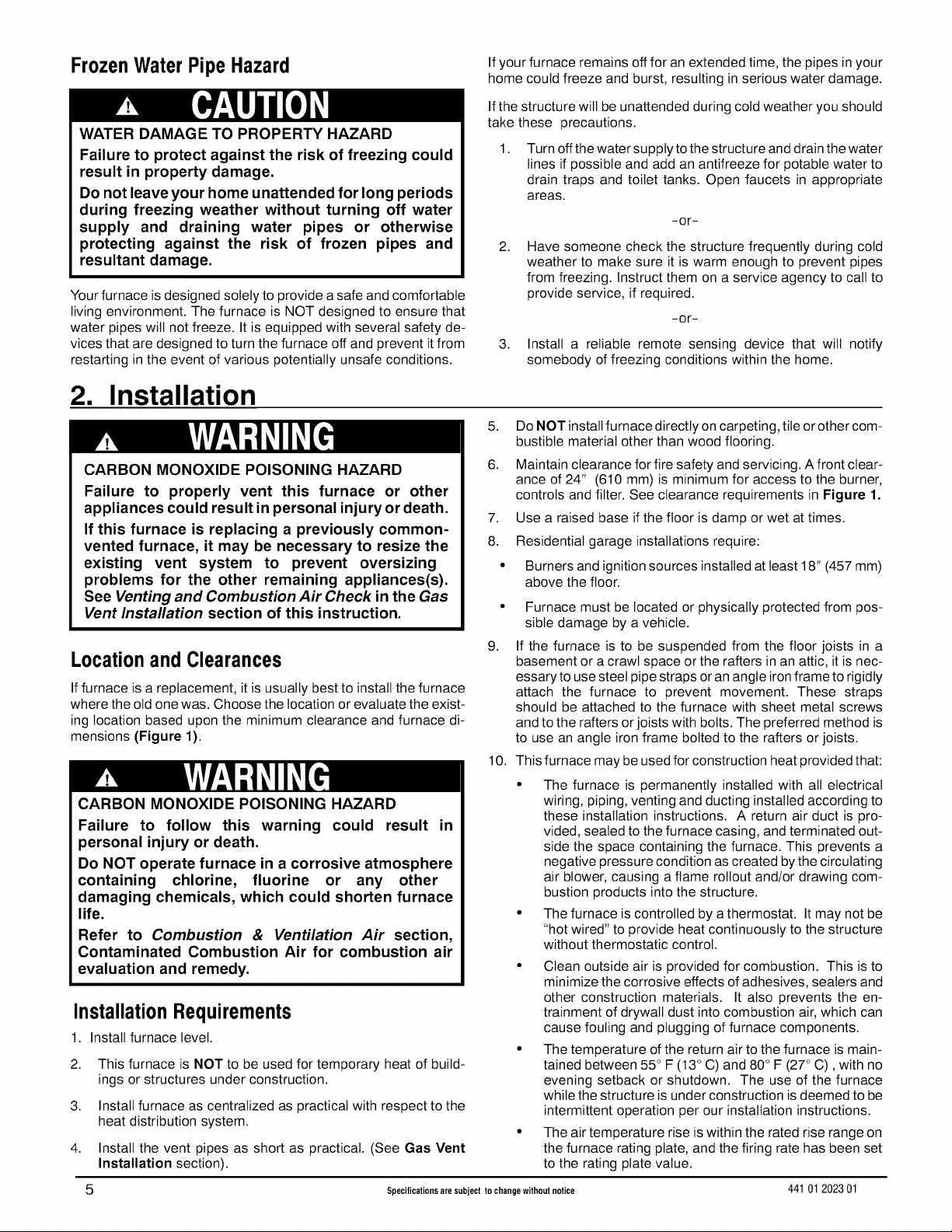
Locationand Clearances
If furnace is a replacement, it is usually best to install the furnace
where the old one was. Choose the location or evaluate the exist-
ing location based upon the minimum clearance and furnace di-
mensions (Figure 1).
CARBON MONOXIDE POISONING HAZARD
Failure to follow this warning could result in
personal injury or death.
Do NOT operate furnace in a corrosive atmosphere
containing chlorine, fluorine or any other
damaging chemicals, which could shorten furnace
life.
Refer to Combustion & Ventilation Air section,
Contaminated Combustion Air for combustion air
evaluation and remedy.
InstallationRequirements
1. Install furnace level.
2,
This furnace is NOT to be used for temporary heat of build-
ings or structures under construction.
3.
Install furnace as centralized as practical with respect to the
heat distribution system.
4.
Install the vent pipes as short as practical. (See Gas Vent
Installation section).
5 Specifications are subject to change without notice 44101 202301
Maintain clearance for fire safety and servicing. A front clear-
ance of 24" (610 mm) is minimum for access to the burner,
controls and filter. See clearance requirements in Figure 1.
7,
Use a raised base ifthe floor isdamp or wet at times.
8.
Residential garage installations require:
Burners and ignition sources installed at least 18" (457 mm)
above the floor.
Furnace must be located or physically protected from pos-
sible damage by a vehicle.
9,
If the furnace is to be suspended from the floor joists in a
basement or a crawl space or the rafters in an attic, it is nec-
essary to use steel pipe straps or an angle iron frame to rigidly
attach the furnace to prevent movement. These straps
should be attached to the furnace with sheet metal screws
and to the rafters or joists with bolts. The preferred method is
to use an angle iron frame bolted to the rafters or joists.
10. This furnace may be used for construction heat provided that:
The furnace is permanently installed with all electrical
wiring, piping, venting and ducting installed according to
these installation instructions. A return air duct is pro-
vided, sealed to the furnace casing, and terminated out-
side the space containing the furnace. This prevents a
negative pressure condition as created bythe circulating
air blower, causing a flame rollout and/or drawing com-
bustion products into the structure.
The furnace is controlled by a thermostat. It may not be
"hot wired" to provide heat continuously to the structure
without thermostatic control.
Clean outside air is provided for combustion. This is to
minimize the corrosive effects of adhesives, sealers and
other construction materials. It also prevents the en-
trainment of drywall dust into combustion air, which can
cause fouling and plugging of furnace components.
The temperature of the return air to the furnace is main-
tained between 55 ° F (13 ° C) and 80° F (27 ° C), with no
evening setback or shutdown. The use of the furnace
while the structure is under construction is deemed to be
intermittent operation per our installation instructions.
The air temperature rise is within the rated rise range on
the furnace rating plate, and the firing rate has been set
to the rating plate value.
Page 6
The filters used to clean the circulating air during the °
construction process must be either changed or thor-
oughly cleaned prior to occupancy.
The furnace, ductwork and filters are cleaned as neces-
sary to remove drywall dust and construction debris from
all HVAC system components after construction is com-
)leted.
After construction is complete,verify proper furnace op-
erating conditions including ignition, gas input rate, air
temperature rise, and venting according to these instal-
lation instructions.
Dimensions and Clearances (*8MPT/*8MPV)
TOP
I , eate *
;iiii!!,i
i
r
.... / ......
5 (127)
.......................................................i
LEFT SIDE
(48)
_-_ 265/8 (676) --_
, BOTTOM
i i J
i , /
J
'_- 231/8 (587) ,_, _- 41/16 (103)
c
(124)i
(25)
DIMENSIONAL INFORMATION
Furnace I Cabinet Top Bottom I ReturnAir
Capacity 15A/2 1B4 6F 1c I o IOpening3/8126/8
*8MPTN050B (76) (356) (1.4) 1(321) 1 H
*8MPTN075F14 191!8 171/2 73/4 21/8 143/4 [
*8MPT100F14 (486) (445) (54) 1(15) I d
*8MPTN100J20 223/4 211/4 91/2 115/16 183/4 j
I I
(152)
(197)
*8MPTN125J20 (578) (540) (241) (49) (476)
* Denotes Brand
Drawingisrepresentative,butsomemodelsmayvary
!
24"(610)min,
ALL DIMENSIONS-IN(MM)
1in =25.4 mm
i _te,_
........................A ..............._
-- B "ii
;J :t /
i ......................................................._
in(mm)
COMBUSTIBLE MATERIALS FOR ALL UNITS
REAR 0
FRONT (combustion air openings in 3" (76 mm)
furnace and in structure)
Required For Service
ALL SIDES Of SUPPLY PLENUM
SIDES
VENT
Single Wall Vent 6" (152 mm)
Type B-1 Double Wall Vent 1" (25 mm)
TOP OF FURNACE 1" (25 mm)
*30" (762ram)clearancerecommendedforfurnaceremoval,
Horizontal)osition:Linecontactispermissibleonlybetweenlines
formedby intersectionsoftopand twosidesof furnacejacket,and
buildingjoists,studsorframing,
MINIMUM CLEARANCES TO
*24" (610 ram)
1" (25 mm)
_o, 281/2 (724) ,_
133/4 (95) _-_ 181/_ 470 _
r_ _ i _ / 3/4 (19)
2 4 /
i ...............................................................................,
(9!o)_
37i
(851)
33 ]i
1) i ...................
3
14 _ I? 1/4-.......................(57!
(749) 1
291/_ Plugged starting hole 131/4 i i i
(440) to cut side duct opening. (337)
i 1'75/16 ....... i i ;
13/4 .... _
(45) _ (124) 261/2 (673)
NOTE:Evaporator"A" coildrainpan dimensions may vary from furnace ductopening size.Always
consultevaporator specificationsfor ductsize requirements.
Furnaceis designedfor bottom return or side return,
Returnairthroughback offurnace isNOT allowed.
7 40
(!7a)_ 0o16)
=47/a _ 215/8 (542) i " 17/8 (48)
0
InstallationPositions
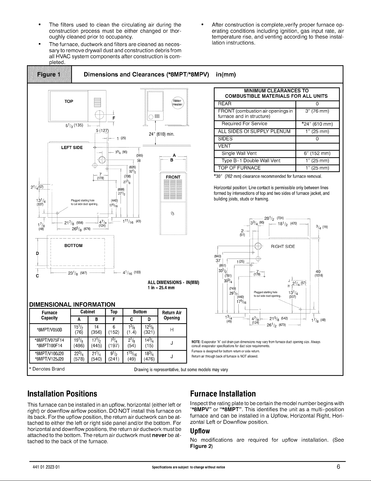
This furnace can be installed in an upflow, horizontal (either teft or
right) or downflow airflow position. DO NOT install this furnace on
its back. For the upflow position, the return air ductwork can be at-
tached to either the left or right side panel and/or the bottom. For
horizontal and downflow positions, the return air ductwork must be
attached to the bottom. The return air ductwork must never be at-
tached to the back of the furnace.
FurnaceInstallation
Inspect the rating plate to be certain the model number begins with
"*8MPV" or "*8MPT'. This identifies the unit as a multi-position
furnace and can be installed in a Upflow, Horizontal Right, Hori-
zontal Left or Downflow position.
Upflow
No modifications are required for upflow installation. (See
Figure 2)
44101 202301 Specifications are subject to change without notice 6
Page 7
The horizontal furnaces may be installed directly on combustible
iiiiiiiiii!i!i T p,ca,up,,ow,nsta,,a,,on
iiiiiiiiiiiiiiiiiiiiiiiiiiiiiiiiiiiiiiiiiiiiiiiiiiiiiiiiiiiiiiiiiiiiiiiiiiiiiiiiiiiiiiiiiiiiiiiiiiiiiiiiiiiiiiiiiiiiiiiiiiiiiiiiiiiiiiiiiiiiiiiiiiii
wood flooring or supports, however, it is recommended for further
fire protection cement board or sheet metal is placed between the
furnace and the combustible wood floor and extend 12" (305 mm)
beyond the front of the furnace louver door. (This is a recommen-
dation only, not a requirement).
This furnace MUST NOT be installed directly on carpeting, tile or
other combustible material other than wood flooring or supports.
Downflow
FIRE HAZARD
Failure to install furnace on noncombustible
subbase could result in personal injury, death
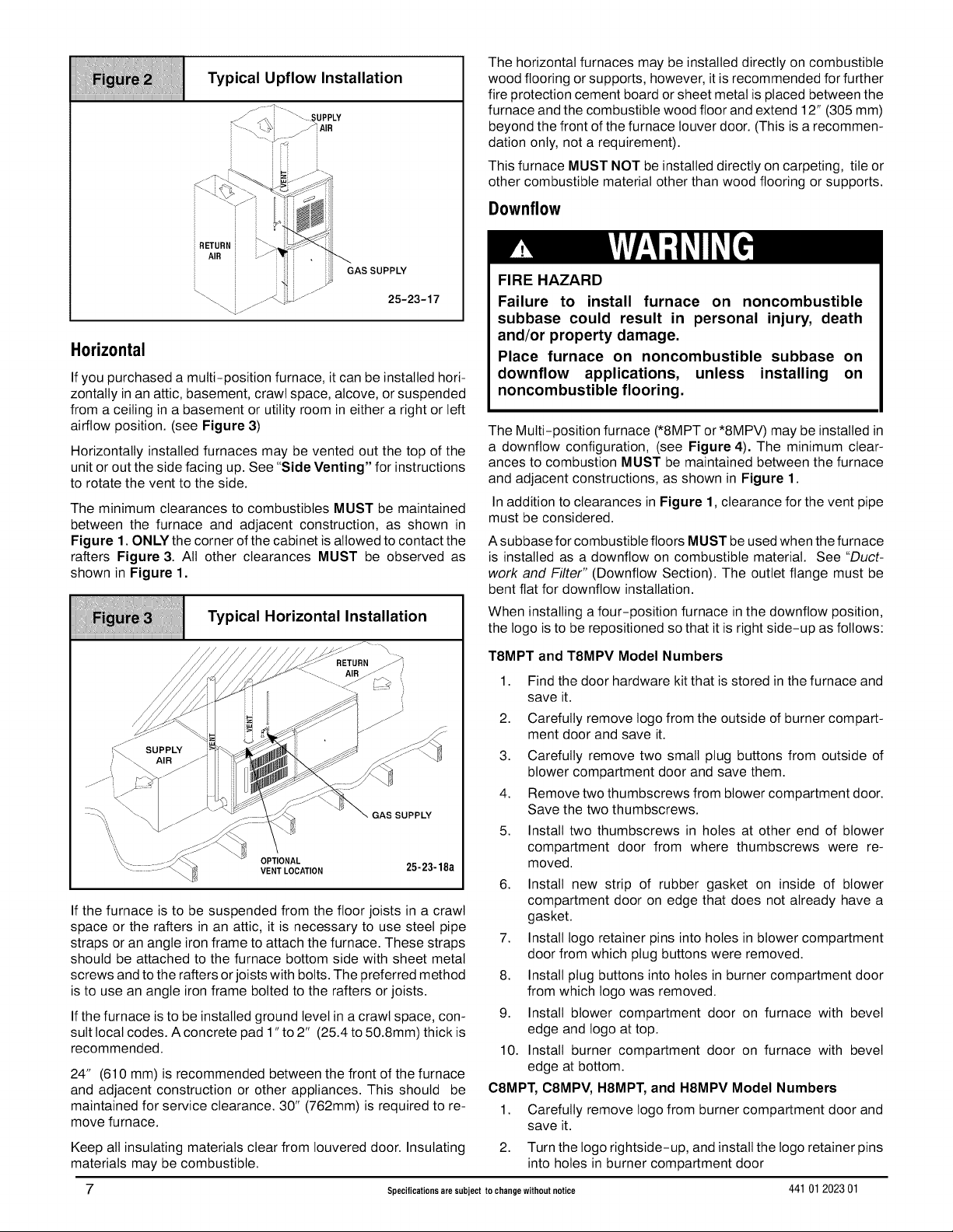
Horizontal
If you purchased a multi-position furnace, it can be installed hori-
zontally inan attic, basement, crawl space, alcove, or suspended
from a ceiling in a basement or utility room in either a right or left
airflow position. (see Figure 3)
Horizontally installed furnaces may be vented out the top of the
unit or out the side facing up. See "Side Venting" for instructions
to rotate the vent to the side.
The minimum clearances to combustibles MUST be maintained
between the furnace and adjacent construction, as shown in
Figure 1. ONLY the corner of the cabinet is allowed to contact the
rafters Figure 3. All other clearances MUST be observed as
shown in Figure 1.
i:i iii
_iii_ i_i Typical Horizontal Installation
iiiiiiiiiiiiiiiiiiiiiiiiiiiiiiiiiiiiiiiiiiiiiiiiiiiiiiiiiiiiiiiiiiiiiiiiiiiiiiiiiiiiiiiiiiiiiiiiiiiiiiiiiiiiiiiiiiiiiiiiiiiiiiiiiiiiiiiiiiiiiiiiiiii
If the furnace is to be suspended from the floor joists in a crawl
space or the rafters in an attic, it is necessary to use steel pipe
straps or an angle iron frame to attach the furnace. These straps
should be attached to the furnace bottom side with sheet metal
screws and to the rafters or joists with bolts. The preferred method
is to use an angle iron frame bolted to the rafters or joists.
If the furnace is to be installed ground level in a crawl space, con-
sult local codes. A concrete pad 1"to 2" (25.4 to 50.8mm) thick is
recommended.
24" (610 mm) is recommended between the front of the furnace
and adjacent construction or other appliances. This should be
maintained for service clearance. 30" (762mm) is required to re-
move furnace.
Keep all insulating materials clear from Iouvered door. Insulating
materials may be combustible.
7 Specifications are subject to change without notice 44101 202301
and/or property damage.
Place furnace on noncombustible subbase on
downflow applications, unless installing on
noncombustible flooring.
The Multi-position furnace (*8MPT or*8MPV) may be installed in
a downflow configuration, (see Figure 4). The minimum clear-
ances to combustion MUST be maintained between the furnace
and adjacent constructions, as shown in Figure 1.
In addition to clearances in Figure 1, clearance for the vent pipe
must be considered.
A subbase for combustible floors MUST be used when the furnace
is installed as a downflow on combustible material. See "Duct-
work and Filter" (Downflow Section). The outlet flange must be
bent flat for downflow installation.
When installing a four-position furnace in the downflow position,
the logo isto be repositioned so that it is right side-up as follows:
T8MPT and T8MPV Model Numbers
1. Find the door hardware kit that is stored inthe furnace and
save it.
2. Carefully remove logo from the outside of burner compart-
ment door and save it.
3. Carefully remove two small plug buttons from outside of
blower compartment door and save them.
4. Remove two thumbscrews from blower compartment door.
Save the two thumbscrews.
5. Install two thumbscrews in holes at other end of blower
compartment door from where thumbscrews were re-
moved.
6. Install new strip of rubber gasket on inside of blower
compartment door on edge that does not already have a
gasket.
7. Install logo retainer pins into holes in blower compartment
door from which plug buttons were removed.
8. Install plug buttons into holes in burner compartment door
from which logo was removed.
9. Install blower compartment door on furnace with bevel
edge and logo at top.
10. Install burner compartment door on furnace with bevel
edge at bottom.
C8MPT, C8MPV, H8MPT, and H8MPV Model Numbers
1. Carefully remove logo from burner compartment door and
save it.
2. Turn the logo rightside-up, and install the logo retainer pins
into holes in burner compartment door
Page 8
3. New labels for rightside-up application on outside of blower
compartment door may be purchased in akit from your dis-
tributor to cover upside-down labels.
T ,ca,oown.ow.nsta.a.,on
iiiiiiiiiiiiiiiiiiiiiiiiiiiiiiiiiiiiiiiiiiiiiiiiiiiiiiiiiiiiiiiiiiiiiiiiiiiiiiiiiiiiiiiiiiiiiiiiiiiiiiiiiiiiiiiiiiiiiiiiiiiiiiiiiiiiiiiiiiiiiiiiiiii
Downflow Venting: The combustion venter MUST be rotated to
vent out the side for all downflow installations, (see Figure 4). Bot-
tom venting is not permitted. See "Side venting" for instructions
to rotate the vent to the side. In addition to rotating the vent to the
side, a Vent Pipe Shield (NAHA002VC) is required to shield the
hot vent pipe.
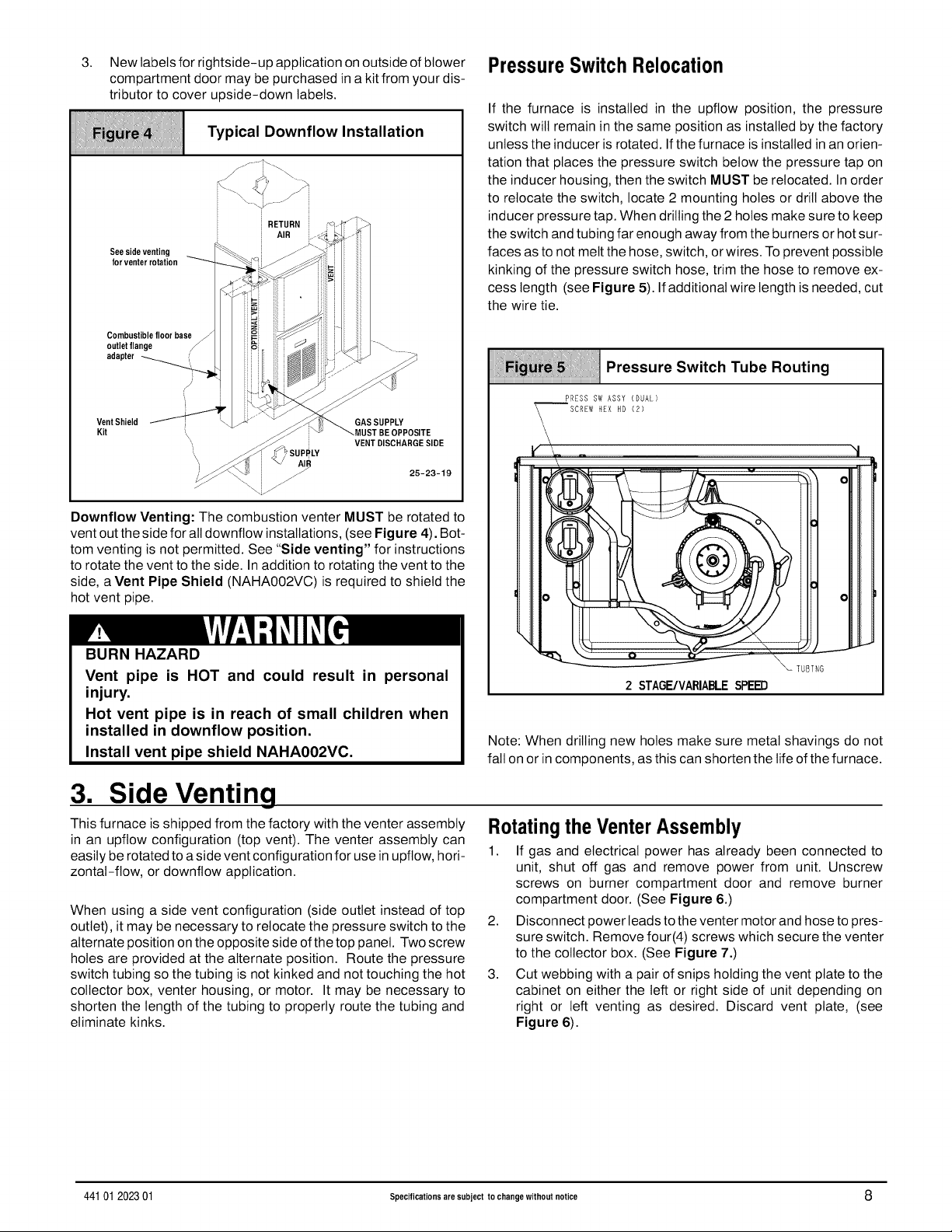
PressureSwitch Relocation
If the furnace is installed in the upflow position, the pressure
switch will remain in the same position as installed by the factory
unless the inducer is rotated. If the furnace is installed in an orien-
tation that places the pressure switch below the pressure tap on
the inducer housing, then the switch MUST be relocated. In order
to relocate the switch, locate 2 mounting holes or drill above the
inducer pressure tap. When drilling the 2 holes make sure to keep
the switch and tubing far enough away from the burners or hot sur-
faces as to not melt the hose, switch, orwires. To prevent possible
kinking of the pressure switch hose, trim the hose to remove ex-
cess length (see Figure 5). If additional wire length is needed, cut
the wire tie.
Pressure Switch Tube Routing
PRESS SW ASSY (DUAL)
SCREW HEX HD (2)
i v
r
!
BURN HAZARD
Vent pipe is HOT and could result in personal
injury.
Hot vent pipe is in reach of small children when
installed in downflow position.
Install vent pipe shield NAHAOO2VC.
3. Side Venting
This furnace isshipped from the factory with the venter assembly
in an upflow configuration (top vent). The venter assembly can
easily be rotated to a side vent configuration for use in upflow, hori-
zontal-flow, or downflow application.
When using a side vent configuration (side outlet instead of top
outlet), it may be necessary to relocate the pressure switch to the
alternate position onthe opposite side ofthe top panel. Two screw
holes are provided at the alternate position. Route the pressure
switch tubing so the tubing is not kinked and not touching the hot
collector box, venter housing, or motor. It may be necessary to
shorten the length of the tubing to properly route the tubing and
eliminate kinks.
TUBTNG
2 STAGE/VARIABLESPEED
Note: When drilling new holes make sure metal shavings do not
fall on or in components, asthis can shorten the life of the furnace.
RotatingtheVenterAssembly
1. If gas and electrical power has already been connected to
unit, shut off gas and remove power from unit. Unscrew
screws on burner compartment door and remove burner
compartment door. (See Figure 6.)
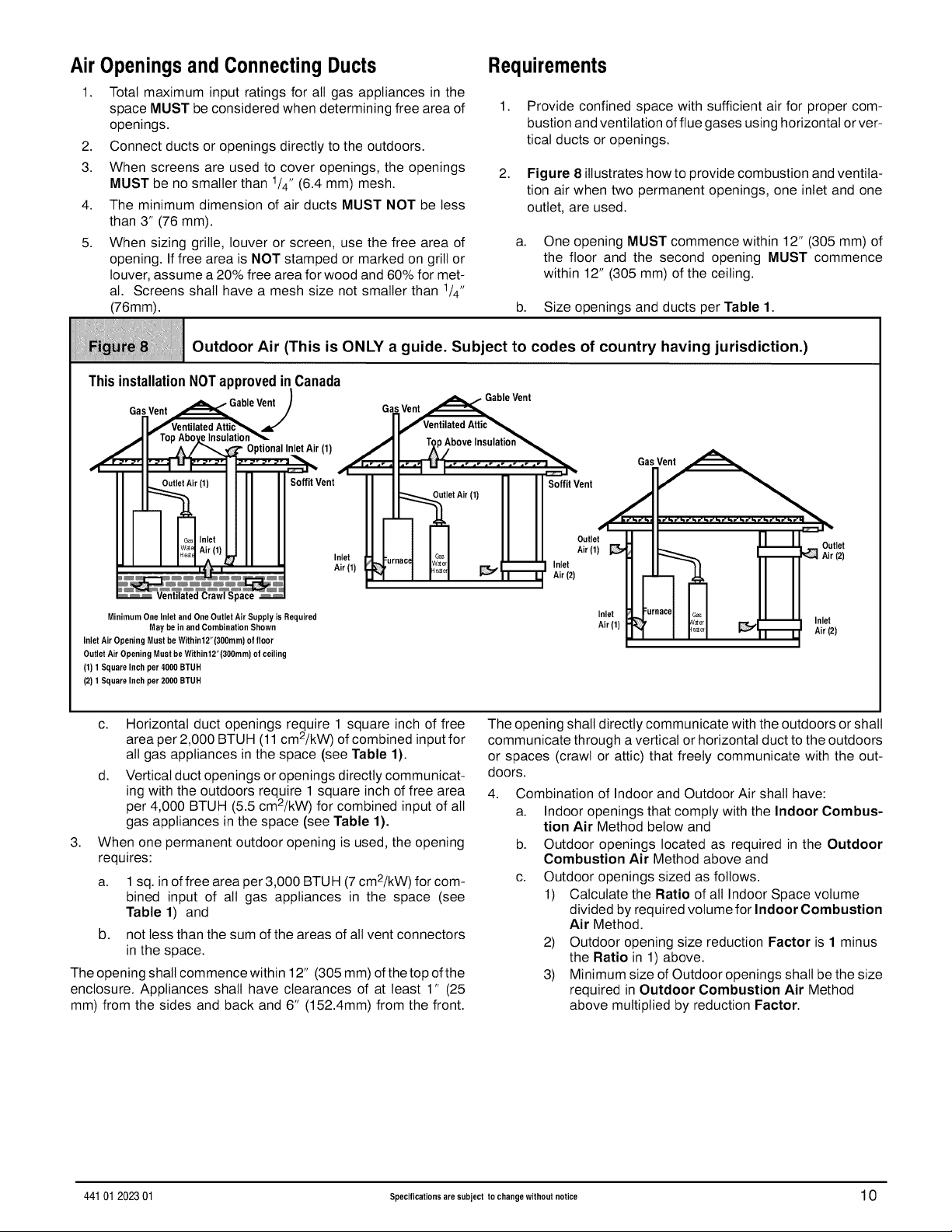
2. Disconnect power leads to the venter motor and hose to pres-
sure switch. Remove four(4) screws which secure the venter
to the collector box. (See Figure 7.)
3. Cut webbing with a pair of snips holding the vent plate to the
cabinet on either the left or right side of unit depending on
right or left venting as desired. Discard vent plate, (see
Figure 6).
44101 202301 Specifications are subject to change without notice 8
Page 9
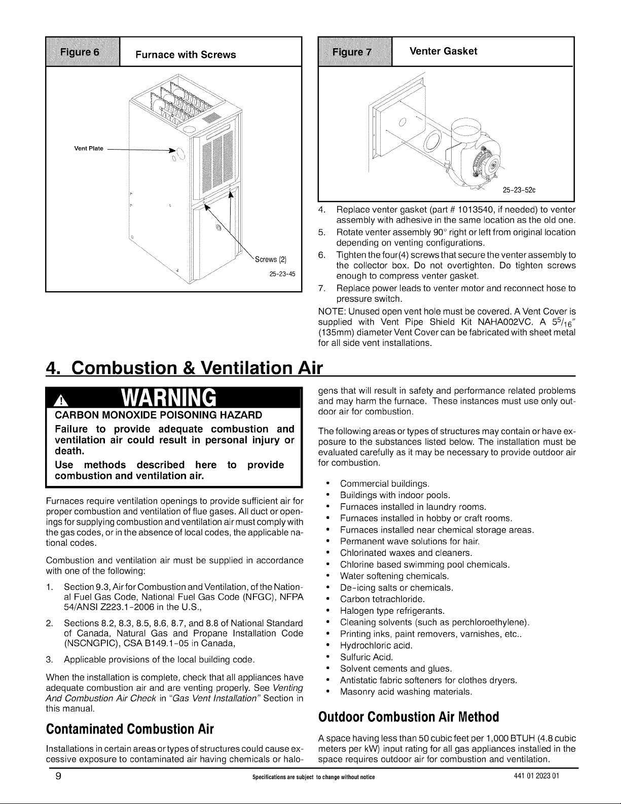
iiiiiiii_iiiiii;iii!iiiiiiiiiii;iii_iii1iii_i1iiiii_i;iii!iiiii1iii!!_ii_iiiiIiiiiiiiii!iiiiiiiiiiii_iiii1;i1iiiiiiiiii_!i_iiii;1iii
l li/ l urnacew,t Screws
iiiiiiiiiiiiiiiiiiiiiiiiiiiiiiiiiiiiiiiiiiiiiiiiiiiiiiiiiiiiiiiiiiiiiiiiiiiiiiiiiiiiiiiiiiiiiiiiiiiiiiiiiiiiiiiiiiiiiiiiiiiiiiiiiiiiiiiiiiiiiiiiiiii
Vent Plate
Venter as et
iiiiiiiiiiiiiiiiiiiiiiiiiiiiiiiiiiiiiiiiiiiiiiiiiiiiiiiiiiiiiiiiiiiiiiiiiiiiiiiiiiiiiiiiiiiiiiiiiiiiiiiiiiiiiiiiiiiiiiiiiiiiiiiiiiiiiiiiiiii....
4. Replace venter gasket (part # 1013540, if needed) to venter
assembly with adhesive in the same location as the old one.
5. Rotate venter assembly 90° right or left from original location
depending on venting configurations.
6. Tighten the four(4) screws that secure the venter assembly to
the collector box. Do not overtighten. Do tighten screws
enough to compress venter gasket.
7. Replace power leads to venter motor and reconnect hose to
pressure switch.
NOTE: Unused open vent hole must be covered. A Vent Cover is
supplied with Vent Pipe Shield Kit NAHA002VC. A 55/16"
(135mm) diameter Vent Cover can be fabricated with sheet metal
for all side vent installations.
4. Combustion & Ventilation Air
gens that will result in safety and performance related problems
and may harm the furnace. These instances must use only out-
CARBON MONOXIDE POISONING HAZARD
Failure to provide adequate combustion and
ventilation air could result in personal injury or
death.
Use methods described here to provide
combustion and ventilation air.
Furnaces require ventilation openings to provide sufficient air for
proper combustion and ventilation of flue gases. All duct or open-
ings for supplying combustion and ventilation air must comply with
the gas codes, or in the absence of local codes, the applicable na-
tional codes.
Combustion and ventilation air must be supplied in accordance
with one of the following:
1. Section 9.3, Air for Combustion and Ventilation, of the Nation-
al Fuel Gas Code, National Fuel Gas Code (NFGC), NFPA
54/ANSI Z223.1-2006 in the U.S.,
2,
Sections 8.2, 8.3, 8.5, 8.6, 8.7, and 8.8 of National Standard
of Canada, Natural Gas and Propane Installation Code
(NSCNGPIC), CSA B149.1-05 in Canada,
3. Applicable provisions of the local building code.
When the installation is complete, check that all appliances have
adequate combustion air and are venting properly. See Venting
And Combustion Air Check in "Gas Vent Installation" Section in
this manual.
ContaminatedCombustionAir
Installations in certain areas or types of structures could cause ex-
cessive exposure to contaminated air having chemicals or halo-
9 Specifications are subject to change without notice 44101 202301
door air for combustion.
The following areas or types of structures may contain or have ex-
posure to the substances listed below. The installation must be
evaluated carefully as it may be necessary to provide outdoor air
for combustion.
• Commercial buildings.
• Buildings with indoor pools.
• Furnaces installed in laundry rooms.
• Furnaces installed in hobby or craft rooms.
• Furnaces installed near chemical storage areas.
• Permanent wave solutions for hair.
• Chlorinated waxes and cleaners.
• Chlorine based swimming pool chemicals.
• Water softening chemicals.
• De-icing salts or chemicals.
• Carbon tetrachloride.
• Halogen type refrigerants.
• Cleaning solvents (such as perchloroethylene).
• Printing inks, paint removers, varnishes, etc..
• Hydrochloric acid.
• Sulfuric Acid.
• Solvent cements and glues.
• Antistatic fabric softeners for clothes dryers.
• Masonry acid washing materials.
OutdoorCombustionAirMethod
A space having less than 50 cubic feet per 1,000 BTUH (4.8cubic
meters per kW) input rating for all gas appliances installed in the
space requires outdoor air for combustion and ventilation.
Page 10
Air Openings and Connecting Ducts
Requirements
1. Total maximum input ratings for all gas appliances in the
space MUST be considered when determining free area of
openings.
2. Connect ducts or openings directly to the outdoors.
3. When screens are used to cover openings, the openings
MUST be no smaller than 1/4" (6.4 mm) mesh.
4. The minimum dimension of air ducts MUST NOT be less
1. Provide confined space with sufficient air for proper com-
bustion and ventilation of flue gases using horizontal or ver-
tical ducts or openings.
2. Figure 8 illustrates how to provide combustion and ventila-
tion air when two permanent openings, one inlet and one
outlet, are used.
than 3" (76 mm).
5. When sizing grille, louver or screen, use the free area of a.
opening. If free area is NOT stamped or marked on grill or
louver, assume a 20% free area for wood and 60% for met-
One opening MUST commence within 12" (305 mm) of
the floor and the second opening MUST commence
within 12" (305 mm) of the ceiling.
al. Screens shall have a mesh size not smaller than 1/4"
(76mm). b. Size openings and ducts perTable 1.
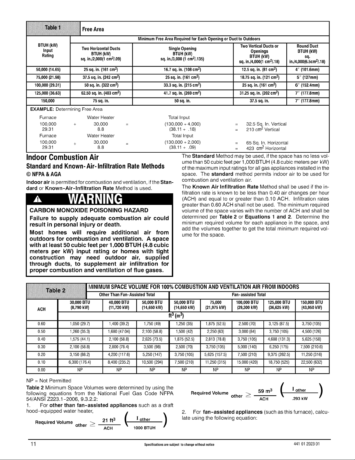
Outdoor Air (This is ONLY a guide. Subject to codes of country having jurisdiction.)
ThisinstallationNOTapprovedinCanada
Gas Vent _,.Gable
/Ventilated AtticS.
T9pAbove Insulation_
I I] I sOffitVent
I I _ ITM
OutletAir (1)
JL I Io sl II I Air(l)
_u ,cI LI _t"_" ,._et
3"I I I'_-°'1 _ _ Air (2)
Minimum One Inletand One Outlet Air Supply is Required
Inlet Air Opening Must be Within12"(300mm} of floor
Outlet Air Opening Must be Within12"(300mm} of ceiling
(1} 1 Square Inch per4000 BTUH
(2} 1 Square Inch per2000 BTUH
c. Horizontal duct openings reguire 1 square inch of free
d. Vertical duct openings or openings directly communicat-
3,
When one permanent outdoor opening is used, the opening
requires:
a.
b,
The opening shall commence within 12" (305 mm) of the top ofthe
enclosure. Appliances shall have clearances of at least 1" (25
mm) from the sides and back and 6" (152.4mm) from the front.
May be in and Combination Shown
area per 2,000 BTUH (11 cmZ/kW) of combined input for
all gas appliances in the space (see Table 1).
ing with the outdoors require 1 square inch of free area
per 4,000 BTUH (5.5 cm2/kW) for combined input of all
gas appliances in the space (see Table 1).
1sq. inof free area per 3,000 BTUH (7 cm2/kW) for com-
bined input of all gas appliances in the space (see
Table 1) and
not tess than the sum of the areas of all vent connectors
in the space.
Vent
o°s
Outlet
Inlet
Air (1)
The opening shall directly communicate with the outdoors or shall
communicate through a vertical or horizontal duct to the outdoors
or spaces (crawl or attic) that freely communicate with the out-
doors.
4, Combination of Indoor and Outdoor Air shall have:
a. Indoor openings that comply with the Indoor Combus-
tion Air Method below and
b. Outdoor openings located as required in the Outdoor
Combustion Air Method above and
c. Outdoor openings sized as follows.
1) Calculate the Ratio of all Indoor Space volume
divided by required volume for Indoor Combustion
Air Method.
2) Outdoor opening size reduction Factor is 1 minus
the Ratio in 1) above.
3) Minimum size of Outdoor openings shall be the size
required in Outdoor Combustion Air Method
above multiplied by reduction Factor.
Outlet
_ Air (2)
Air (2)
44101 202301 Specifications are subject to change without notice 10
Page 11
iiiiiiiiiiiiiiiiiiiiiiiiiiiiiiiiiiiiiiiiiiiiiiiiiiiiiiiiiiiiiiiiiiiiiiiiiiiiiiiiiiiiiiiiiiiiiiiiiiiiiiiiiiiiiiiiiiiiiiiiiiiiiiiiiiiiiiiiiiiiiiiiiiiiiiiiiiiiiiiiiiiiiiiiiiiiiiiiiiiiiiiiiiiii
BTUH(kW) TwoVerticalDuctsor RoundDuct
Input TwoHorizontalDucts SingleOpening Openings BTUH(kW)
Rating BTUH(kW) BTUH(kW) BTUH(kW) sq.
50,000 (14.65) 25sq.in.(161 cm2) 16.7sq.in.(108 cm2) 12.5sq.in.(81 cm 2) 4" (101.6mm)
75,000 (21.98) 37.5sq.in.(242 cm2) 25sq.in.(161 cm2) 18.75sq.in.(121 cm2) 5" (127mm)
100,000 (29.31) 50sq.in.(322 cm2) 33.3sq.in.(215 cm2) 25sq.in.(161 cm2) 6" (152.4mm)
125,000 (36.63) 62.50sq.in.(403 cm2) 41.7sq.in.(269 cm2) 31.25sq.in.(202 cm2) 7" (177.8mm)
150,000 75sq.in. 50sq.in. 37.5sq.in. 7" (177.8mm)
EXAMPLE: Determining Free Area
Furnace Water Heater Total Input
100,000 + 30,000 = (130,000 +4,000) = 32.5 Scj. In. Vertical
29.31 8.8 (38.11 + .18) = 210 cmLVertical
Furnace Water Heater Total Input
100,000 + 30,000 = (130,000 +2,000) = 65 Sq. In. Horizontal
29.31 8.8 (38.11 + .09) = 423 cm2 Horizontal
IndoorCombustionAir
Standardand Known-Air-Infiltration Rate Methods
© NFPA & AGA
Indoor air is permitted for combustion and ventilation, if the Stan-
dard or Known-Air-Infiltration Rate Method is used.
CARBON MONOXIDE POISONING HAZARD
Failure to supply adequate combustion air could
result in personal injury or death.
Most homes will require additional air from
outdoors for combustion and ventilation. A space
Free Area
MinimumFreeAreaRequiredfor EachOpeningorDucttoOutdoors
sq.in./2,000(1 cm2/.09) sq. in./3,000 (1 cm2/.135) sq. in./4,000(1 cm2/.18) in./4,000(6.5cm2/.18)
The Standard Method may be used, if the space has no tess vol-
ume than 50 cubic feet per 1,000 BTUH (4.8 cubic meters per kW)
of the maximum input ratings for all gas appliances installed in the
space. The standard method permits indoor air to be used for
combustion and ventilation air.
The Known Air Infiltration Rate Method shall be used if the in-
filtration rate is known to be less than 0.40 air changes per hour
(ACH) and equal to or greater than 0.10 ACH. Infiltration rates
greater than 0.60 ACH shall not be used. The minimum required
volume of the space varies with the number of ACH and shall be
determined per Table 2 or Equations 1 and 2. Determine the
minimum required volume for each appliance in the space, and
add the volumes together to get the total minimum required vol-
ume for the space.
with at least 50 cubic feet per 1,ODDBTUH (4.8 cubic
meters per kW) input rating or homes with tight
construction may need outdoor air, supplied
through ducts, to supplement air infiltration for
proper combustion and ventilation of flue gases.
,::' MINIMUM SPACE VOLUME FOR 100% COMBUSTION AND VENTILATION AIR FROM INDOORS
OtherThanFan-AssistedTotal Fan-assistedTotal
30,000BTU 40,000BTU 50,000BTU 50,000BTU 75,000 100,000BTU 125,000BTU 150,000BTU
ACH (8,790kW) (11,720kW) (14,650kW) (14,650kW) (21,975kW) (29,300kW) (36,625kW) (43,950kW)
ft3(m3)
0.60 1,050 (29.7) 1,400 (39.2) 1,750 (49) 1,250 (35) 1,875 (52.5) 2,500 (70) 3,125 (87.5) 3,750 (105)
0.50 1,260 (35.3) 1,680 (47.04) 2,100 (58.8) 1,500 (42) 2,250 (63) 3,000 (84) 3,750 (105) 4,500 (126)
0.40 1,575 (44.1) 2,100 (58.8) 2,625 (73.5) 1,875 (52.5) 2,813 (78.8) 3,750 (105) 4,688 (131.3) 5,625 (158)
0.30 2,100 (58.8) 2,800 (78.4) 3,500 (98) 2,500 (70) 3,750 (105) 5,000 (140) 6,250 (175) 7,500 (210.6)
0.20 3,150 (88.2) 4,200 (117.6) 5,250 (147) 3,750 (105) 5,625 (157.5) 7,500 (210) 9,375 (262.5) 11,250 (316)
0.10 6,300 (176.4) 8,400 (235.2) 10,500 (294) 7,500 (210) 11,250 (315) 15,000 (420) 18,750 (525) 22,500 (632)
0.00 NP NP NP NP NP NP NP NP
NP = Not Permitted
Table 2 Minimum Space Volumes were determined by using the
following equations from the National Fuel Gas Code NFPA
54/ANSI Z223.1-2006, 9.3.2.2:
1. For other than fan-assisted appliances such as a draft
hood-equipped water heater,
-- ACH 1000 BTUH
°soueOVoumOo,.e>'0''( '°t"er)
-- ACH .293 kW
2. For fan-assisted appliances (such as this furnace), calcu-
late using the following equation:
11 Specifications are subject to change without notice 441 01202301
Page 12
Required Volume fan_ 15ft3 ( If an )
ACH 1000 BTUH
RequiredV°lume fan_ "42m3 ( If an /
ACH .293 kW
2.
For fan-assisted appliances such as this furnace,
If:
] other = combined inputof all other than fan-assisted
appliances in BTUH
I fan = combined input of all fan-assisted appliances in
BTUH
ACH = air changes per hour (ACH shall not exceed 0.60)
The following requirements apply to the Standard Method and to
the Known Air Infiltration Rate Method.
• Adjoining rooms can be considered part of a space, if there
are no closable doors between rooms.
An attic or crawl space may be considered aspace that freely
communicates with the outdoors provided there are ade-
quate ventilation openings directly to outdoors. Openings
MUST remain open and NOT have any means of being
closed off. Ventilation openings to outdoors MUST be at least
5. Gas Vent Installation
CARBON MONOXIDE POISONING HAZARD
Failure to properly vent this furnace could result
in personal injury or death.
Use methods described here to provide combus-
tion and ventilation air.
Install the vent in compliance with codes of the country having ju-
risdiction, local codes or ordinances and these instructions.
This Category ! furnace is fan-assisted.
Category ! furnace definition: A central furnace which operates
with a non-positive vent static pressure and with a flue loss not
less than 17 percent. These furnaces are approved for common-
venting and multi-story venting with other fan-assisted or draft
hood-equipped appliances in accordance with the NFGC or
NSCNGPIC.
CategoryI SafeVentingRequirements
Category [ furnace vent installations shall be in accordance with
Parts 10 and 13 of the National Fuel Gas Code (NFGC), NFPA
54/ANSI Z223.1-2006; and/or Section 8 and Appendix C of the
CSA B149.1-05, National Standard of Canada, Natural Gas and
Propane Installation Code; the local building codes; furnace and
vent manufacturer's instructions.
NOTE: The following instructions comply with the NFPA 54/ANSI
Z223.1-2006 National Fuel Gas Code and CSA B149.1 Natural
Gas and Propane Installation code, based on the High-Heat
input rate on the furnace rating plate.
1. If a Category ! vent passes through an attic, any concealed
space or floor, use ONLY Type B or Type L double wall vent
pipe. If vent pipe passes through interior wall, use type B vent
pipe with ventilated thimble ONLY.
2. Do NOT vent furnace into any chimney serving an open fire-
place or solid fuel burning appliance.
1square inch of free area per 4,000 BTUH of total input rating
for all gas appliances in the space.
• In spaces that use the Indoor Combustion Air Method, in-
filtration should be adequate to provide air for combustion,
ventilation and dilution of flue gases. However, in buildings
with unusually tight construction, additional air MUST
be provided using the methods described in section
titled Outdoor Combustion Air Method:
• Unusually tight construction is defined as Construction with
1. Wails and ceilings exposed to the outdoors have a con-
tinuous, sealed vapor barrier. Openings are gasketed or
sealed and
2. Doors and openabte windows are weather stripped and
3. Other openings are caulked or sealed. These include
joints around window and door frames, between sole
plates and floors, between walt-ceiling joints, between
wall panels, at penetrations for plumbing, electrical and
gas lines, etc.
VentilationAir
Some provincial codes and local municipalities require ventilation
or make-up air be brought intothe conditioned space as replace-
ment air. Whichever method is used, the mixed return air tempera-
ture across the heat exchanger MUST not fall below 60°
continuously, or 55° on an intermittent basis so that flue gases will
not condense excessively inthe heat exchanger. Excessive con-
densation will shorten the life of the heat exchanger and possibly
void your warranty.
3. Use the same diameter Category ! connector or pipe as per-
mitted by:
• by the National Fuel Gas Code Code (NFGC) NFPA
54/ANSI Z223.1-2006 Sections 12 and 13 venting re-
quirements in the United States
or
• the National Standard of Canada Natural Gas and Pro-
pane Installation Code (NSCNGPIC) CSA B149.1-05
Section 8 and appendix C venting requirements in Cana-
da.
4. Push the vent connector onto the furnace flue collar of the
venter assembly until it touches the bead (at least 5/8" over-
lap) and fasten with at least two field-supplied, corrosion-re-
sistant, sheet metal screws located at least 140° apart.
5. Keep vertical Category ! vent pipe or vent connector runs as
short and direct as possible.
6. Vertical outdoor runs of Type-B or ANY single walt vent pipe
below the roof line are NOT permitted.
7. Slope all horizontal runs upwards from furnace to the vent ter-
minal a minimum of 1/4" per foot (21 mm/m).
8. Rigidly support all horizontal portions of the venting system
every 6' (1.8m)or less using proper clamps and metal straps
to prevent sagging and ensure there is no movement after
installation.
9. Check existing gas vent or chimney to ensure they meet
clearances and local codes. See Figure 1
10. The furnace MUST be connected to afactory built chimney or
vent complying with a recognized standard, or a masonry or
concrete chimney lined with a lining material acceptable to
the authority having jurisdiction. Venting into an unlined
masonry chimney or concrete chimney is prohibited.
See the Masonry Chimney Venting section in these in-
structions.
11. Fan-assisted combustion system Category ! furnaces shall
not be vented into single-wall metal vents.
12. Category ! furnaces must be vented vertically or nearly verti-
cally, unless equipped with a listed mechanical venter.
13. Vent connectors serving Category I furnaces shall not be
connected into any portion of mechanical draft systems oper-
ating under positive pressure.
44101 202301 Specifications are subject to change without notice 12
Page 13
VentingandCombustionAir Check
NOTE: When an existing Category ! furnace is removed or re-
placed, the original venting system may no longer be sized to
properly vent the attached appliances, and to make sure there is
adequate combustion air for all appliances, MAKE THE FOL-
LOWING CHECK.
CARBON MONOXIDE POISONING HAZARD
Failure to follow the steps outlined below for each
appliance connected to the venting system being placed
into operation, could result in carbon monoxide poisoning
or death:
The following steps shall be followed for each appliance
connected to the venting system being placed into
operation, while all other appliances connected to the
venting system are not in operation:
1. Seal any unused openings in the venting system.
2. Inspect the venting system for proper size and horizontal
pitch, as required in the National Fuel Gas Code, NFPA
54/ANSI Z223. 1-2006 or CSA B149. 1,Natural Gas and Pro-
pane Installation Code and these instructions. Determine
that there is no blockage or restriction, leakage, corrosion
and other deficiencies which could cause an unsafe condi-
tion.
3. As far as practical, close all building doors and windows and
all doors between the space in which the appliance(s) con-
nected to the venting system are located and other spaces of
the building.
4. Close fireplace dampers.
5. Turn on clothes dryers and any appliance not connected to
the venting system. Turn on any exhaust fans, such as range
hoods and bathroom exhausts, so they are operating at max-
imum speed. Do not operate a summer exhaust fan.
6. Follow the lighting instructions. Place the appliance being in-
spected into operation. Adjust the thermostat so appliance is
operating continuously.
7. Test for spillage from draft hood equipped appliances at the
draft hood relief opening after 5 minutes of main burner op-
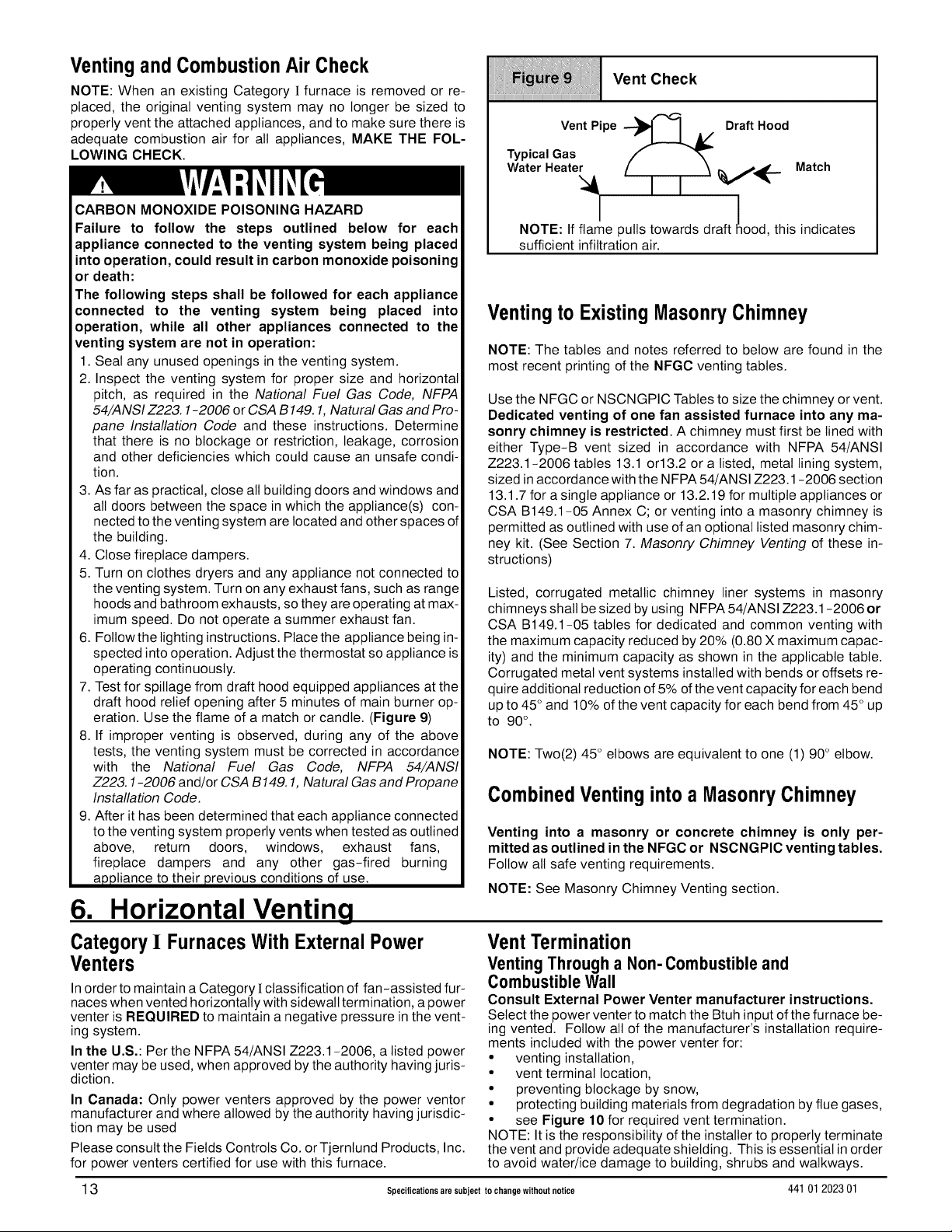
eration. Use the flame of a match or candle. (Figure 9)
8. If improper venting is observed, during any of the above
tests, the venting system must be corrected in accordance
with the National Fuel Gas Code, NFPA 54/ANSI
Z223. 1-2006 and/or CSA B149.1, Natural Gas and Propane
Installation Code.
9. After it has been determined that each appliance connected
to the venting system properly vents when tested as outlined
above, return doors, windows, exhaust fans,
fireplace dampers and any other gas-fired burning
appliance to their previous conditions of use.
iiiiiiiiiiiiiiiiiiiiiiiiiiiiiiiiiiiiiiiiiiiiiiiiiiiiiiiiiiiiiiiiiiiiiiiiiiiiiiiiiiiiiiiiiiiiiiiiiiiiiiiiiiiiiiiiiiiiiiiiiiiiiiiiiiiiiiiiiiii....
Vent Pipe --_ I A/ Draft Hood
Typical Gas
Water Heate_ I I V_('-" Match
NOTE: If flame pulls towards draft ood, this indicates
sufficient infiltration air.
Ventingto ExistingMasonryChimney
NOTE: The tables and notes referred to below are found in the
most recent printing of the NFGC venting tables.
Use the NFGC or NSCNGPIC Tables to size the chimney or vent.
Dedicated venting of one fan assisted furnace into any ma-
sonry chimney is restricted. A chimney must first be lined with
either Type-B vent sized in accordance with NFPA 54/ANSI
Z223.1-2006 tables 13.1 or13.2 or a listed, metal lining system,
sized in accordance with the NFPA 54/ANSI Z223.1-2006 section
13.1.7 for a single appliance or 13.2.19 for multiple appliances or
CSA B149.1-05 Annex C; or venting into a masonry chimney is
permitted as outlined with use of an optional listed masonry chim-
ney kit. (See Section 7. Masonry Chimney Venting of these in-
structions)
Listed, corrugated metallic chimney liner systems in masonry
chimneys shall be sized by using NFPA 54/ANSI Z223.1-2006 or
CSA B149.1-05 tables for dedicated and common venting with
the maximum capacity reduced by 20% (0.80 X maximum capac-
ity) and the minimum capacity as shown in the applicable table.
Corrugated metal vent systems installed with bends or offsets re-
quire additional reduction of 5% of the vent capacity for each bend
up to 45° and 10% of the vent capacity for each bend from 45 ° up
to 90°.
NOTE: Two(2) 45 ° elbows are equivalent to one (1) 90° elbow.
CombinedVentinginto a MasonryChimney
Venting into a masonry or concrete chimney is only per-
mitted as outlined in the NFGC or NSCNGPIC venting tables.
Follow all safe venting requirements.
NOTE: See Masonry Chimney Venting section.
VentCheck
i !
6. Horizontal Venting
CategoryI FurnacesWith ExternalPower
Venters
In order to maintain a Category ! classification of fan-assisted fur-
naces when vented horizontally with sidewall termination, a power
venter is REQUIRED to maintain a negative pressure in the vent-
ing system.
In the U.S.: Per the NFPA 54/ANSI Z223.1-2006, a listed power
venter may be used, when approved by the authority having juris-
diction.
In Canada: Only power venters approved by the power ventor
manufacturer and where allowed by the authority having jurisdic-
tion may be used
Please consult the Fields Controls Co. or Tjernlund Products, Inc.
for power venters certified for use with this furnace.
13 Specifications are subject to change without notice 44101 202301
VentTermination
VentingThrough a Non-Combustible and
Combustible Wall
Consult External Power Venter manufacturer instructions.
Select the power venter to match the Btuh input of the furnace be-
ing vented. Follow all of the manufacturer's installation require-
ments included with the power venter for:
• venting installation,
• vent terminal location,
• preventing blockage by snow,
• protecting building materials from degradation by flue gases,
• see Figure 10 for required vent termination.
NOTE: It is the responsibility of the installer to properly terminate
the vent and provide adequate shielding. This is essential in order
to avoid water/ice damage to building, shrubs and walkways.
Page 14

Other than Direct Vent Termination Clearance
A
.......-r...............
.............. /
............. / i
//
/'
//
,/
i
25-24-65-2
D VENTTERMINAL \ /_
Item Clearance Descriptions
A Clearance above grade, veranda, porch, deck, balcony, or
anticipated snow level
B Clearance to a window or door that may be opened
%X/' A R SUPPLY NLET
Canadian Installation (1)
12 inches (30cm) #
6 inches (15 cm) for appliances -< 10,000 Btuh (3 kW)
12 inches ( 30 cm) for appliances > 10,ooo Btuh (3 kWO)
and -< 100,go0 Btuh (30 kW), 36 inches (91 cm) for
appliances > t00,000 Btuh (30 kW)
AREA WHERE TERMINAL IS NOT PERMITED
U.S. Installation (2)
12 inches (30 cm)
4 feet(1.2 m) below or to the side of the opening. 1 foot (30 cm
above the opening.
C Clearance to a permanently closed window
D Vortical clearance to aventilated soffit located above the
terminal within a horizontal distance of 2"(61cm) tram the
centerline of the terminal
E Clearance to an unventilated soffit
F Clearance to an outside corner
G Clearance to an inside corner
H Clearance to each side of the centerline extended above
electrical meter or gas service regulator assembly
I Clearance to service regulator vent outlet
J Clearance to non-mechanical air supply inlet to building or
the combustion air inlet to any other appliance
K
Clearance to a mechanical air supply inlet
L
Clearance under a veranda, porch, deck, or balcony
M
Clearance to each side of the centerline extended above or
below vent terminal of the furnace to a dryer or water heater
vent, or other appliance's direct vent intake or exhaust.
N Clearance to the vent terminal of a dryer vent, water heater
vent, or other appliances direct vent intake or exhaust.
O Clearance from a plumbing vent stack
p Clearance above paved sidewalk or paved 7 feet (2.13m)**
driveway located on public property
(1.) In accordance with the current CSA B149.1, Natural Gas and Predane Installation Code
(2.) In accordanoe with the current NFPA 54/ANSI Z223.1 ,National Fuel Gas Code
# 18" (46 am) above roof surface
3 feet (91 cm) within 15 feet(4.5 m) above the meter/regulator
assembly
3 feet (91 ore)
6 inches (15 cm) for appliances -< 10,000 Btuh (3 kW)
12 inches ( 30 cm) for appliances > 10,000 Btuh (3 kW0)
and -< 10Or000 Btuh (30 kW)
36 inches (91 cm) for appliances > 100,000 Btuh (30 kW)
5 feet(1.83 m)
12 inches(30 cm) +
3 feet (91 cm) w_thin 15 feet (4.5 m) above the meter/regulator
assembly
4 feet (t .2 m) below or to the side of opening: 1 foot (30 sin)
above opening.
3 feet (91 cm) above if wi_in 10 feet (3 m horizontally)
7 feet (2.13m)
+ Permitted only if veranda, porch, deck, or balcony is fully open on a minimum oftwo sides beneath the floor.
For clearances not specified in NFPA 54/ANSI Z22S.1 or CSA B149. t, clearances shall be inaccordance with local installation codes and the requiremenls of the gas supplier and the
Manufacturer's installation instructions.
** A vent shall not terminate above 8. sidewalk or paved driveway that is located between two single family dwellings and serves beth dwellings.
Notes:
t. The vent for this appliance shall not terminate
a. Over publicwalkways; or
b. Near soffit vents or crawl space vents or other areas where condensate er vapor could create a nusiance or hazard or property damage: or
c. Where condensate vapor could cause damage or could be detrimental to the operation of regulators, relief valves, or other equipment.
2. When locating vent terminations, consideration must be given to prevailing winds, location, and other conditions which may cause recirculation of the combustiob products of adjacent vents.
Recirculation can cause poor combustion, inlet condensate problems, and accelerated corrosion of the heat exchangers.
3 Avoid venting under a deck or large overhang. Recirculatien could occur and cause performance or system problems. A05013
44101 202301 Specifications are subject to change without notice 14
Page 15

7. Masonry Chimney Venting
ChimneyInspection
All masonry chimney construction must conform to Standard
NFPA 211-2006 and to any state or local codes applicable. The
chimney must be in good condition and a complete chimney in-
spection must be conducted prior to furnace installation. If the in-
spection reveals damage or abnormal conditions, make
necessary repairs or seek expert help. See "The Chimney Inspec-
tion Chart" Figure 11. Measure inside area of tile-liner and exact
height of chimney from the top of the chimney to the highest ap-
pliance flue collar or drafthood outlet.
Connector Type
To reduce flue gas heat loss and the chance of condensate prob-
lems, the vent connector must be double-wall Type Bvent except
as specified in the listed kit.
Venting Restrictionsfor ChimneyTypes
Interior Chimney - has no sides exposed to the outdoors below
the roofiine. All installations can be single furnace or common
vented with another draft hood equipped Category [ appliance.
Exterior Chimney - has one or more sides exposed to the out-
doors below the roof line. All installations with a 99% Winter De-
sign Temperature* below 17°F (-8°C) must be common vented
only with a draft hood equipped Category ! appliance.
* The 99% Winter Design Dry-Bulb (db) temperatures are
found in the 2005 ASHRAE Fundamentals Handbook CD
and Chapter 28.
CARBON MONOXIDE POISONING, FIRE AND
EXPLOSION HAZARD
Failure to properly vent this furnace could result in
personal injury, death and/or property damage.
These furnaces are CSA (formerly AGA and CGA)
design-certified for venting into exterior clay
tile-lined masonry chimneys with a factory
accessory Chimney Adapter Kit. Refer to the
furnace rating plate for correct kit usage. The
Chimney Adapter Kits are for use with ONLY
furnaces having a Chimney Adapter Kit number
marked on the furnace rating plate.
If a clay tile-lined masonry chimney is being used and it is ex-
posed to the outdoors below the roof line, relining might be re-
quired. Chimneys shall conform to the Standard for Chimneys,
Fireplaces, Vents, and Solid Fuel Burning Appliances NFPA
211-2006 in the United States and to a Provincial or Territorial
Building Code in Canada (in its absence, the National Building
Code of Canada) and must be in good condition.
U.S.A.-Refer to Sections 13.1.8 and 13.2.20 of the NFPA
54/ANSI Z223.1-2006 orthe authority having jurisdiction to deter-
mine whether relining is required. If relining is required, use a
properly sized listed metal liner, Type-B vent, or a listed alterna-
tive venting design.
NOTE: See the NFPA 54/AN SI Z223.1-2006, 13.1.8 and 13.2.20
regarding alternative venting design and the exception, which
cover installations such as the Chimney Adapter Kits
NAHA001DH and NAHA002DH, which are listed for use with
these furnaces.
The Chimney Adapter Kit are listed alternative venting design for
these furnaces. See the kit instructions for complete details.
Canada (and U.S.A.)-This furnace is permitted to be vented into
a clay tile-lined masonry chimney that is exposed to the outdoors
below the roof line, provided:
1. Vent connector is Type-B double-wall, and
2. This furnace is common vented with at least 1 draft hood-
equipped appliance, and
3,
The combined appliance input rating is less than the maxi-
mum capacity given in Table A, and
4.
The input rating of each space-heating appliance is greater
than the minimum input rating given in Table B for Masonry
Chimneys for the local 99% Winter Design Temperature.
Chimneys having internal areas greater than 38 square
inches require furnace input ratings greater than the input
ratings of these furnaces. See footnote at bottom of Table
B, and
5. The authority having jurisdiction approves.
If all of these conditions cannot be met, an alternative venting de-
sign shall be used, such as the listed chimney adapter kit with a
furnace listed for use with the kit, a listed chimney-lining system,
or a Type-B vent.
15 Specifications are subject to change without notice 44101 202301
Page 16
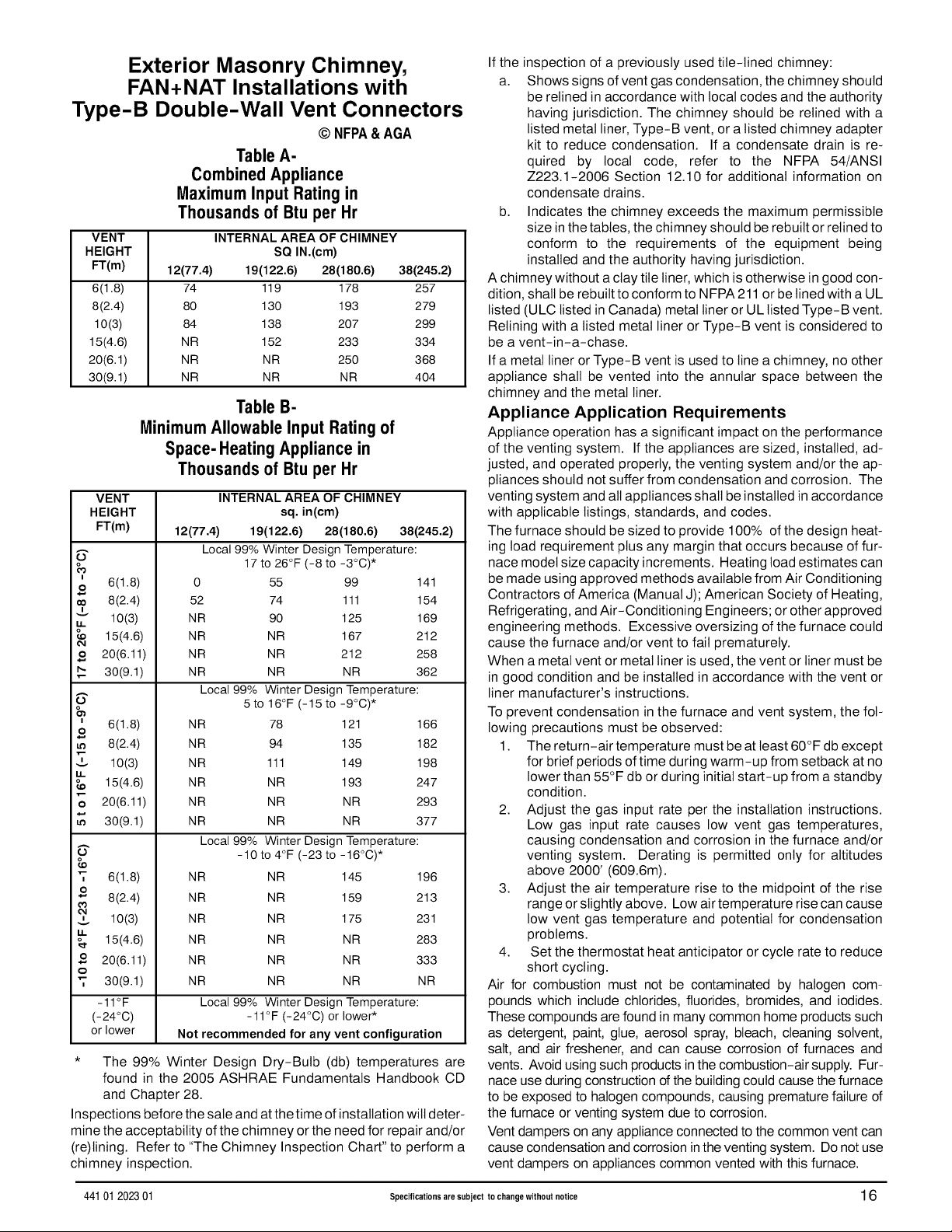
Exterior Masonry Chimney,
FAN+NAT Installations with
Type-B Double-Wall Vent Connectors
© NFPA& AGA
TableA-
CombinedAppliance
MaximumInput Rating in
Thousandsof Btu per Hr
VENT
HEIGHT
FT(m)
6(1.8)
8(2.4)
10(3)
15(4.6)
20(6.1)
30(9.1)
12(77.4) 19(122.6) 28(180.6) 38(245.2)
MinimumAllowable Input Ratingof
Space- HeatingAppliance in
VENT INTERNAL AREA OF CHIMNEY
HEIGHT sq. in(cm)
FT(m) 12(77.4) 19(122.6) 28(180.6) 38(245.2)
o
I
6(1.8) 0
O
_o
8(2.4) 52
I
v
10(3) NR
14.
15(4.6) NR
20(6.11) NR
o
30(9.1) NR
o
I
6(1.8)
O
8(2.4)
I
10(3)
15(4.6)
20(6.11)
O
30(9.1)
'T
6(1.8) NR
o
8(2.4) NR
10(3) NR
15(4.6) NR
o
20(6.11) NR
o
'T
30(9.1) NR
- 11°F Local 99% Winter Design Temperature:
(-24°C) -11°F (-24°C) or lower*
or lower Not recommended for any vent configuration
* The 99% Winter Design Dry-Bulb (db) temperatures are
found in the 2005 ASHRAE Fundamentals Handbook CD
and Chapter 28.
Inspections before the sale and at the time ofinstallation wilt deter-
mine the acceptability of the chimney or the need for repair and/or
(re)lining. Refer to "The Chimney Inspection Chart" to perform a
chimney inspection.
INTERNALAREA OF CHIMNEY
SQ IN.(cm)
74 119 178 257
80 130 193 279
84 138 207 299
NR 152 233 334
NR NR 250 368
NR NR NR 404
Table B-
Thousandsof Btu per Hr
Local 99% Winter Design Temperature:
17 to 26°F (-8 to -3°C) *
55 99 141
74 111 154
90 125 169
NR 167 212
NR 212 258
NR NR 362
Local 99% Winter Design Temperature:
5to 16°F (-15 to -9°C) *
NR 78 121 166
NR 94 135 182
NR 111 149 198
NR NR 193 247
NR NR NR 293
NR NR NR 377
Local 99% Winter Design Temperature:
-10 to 4°F (-23 to -16°C) *
NR 145 196
NR 159 213
NR 175 231
NR NR 283
NR NR 333
NR NR NR
If the inspection of a previously used tile-lined chimney:
a. Shows signs of vent gas condensation, the chimney should
be relined in accordance with local codes and the authority
having jurisdiction. The chimney should be relined with a
listed metal liner, Type-B vent, or a listed chimney adapter
kit to reduce condensation. If a condensate drain is re-
quired by local code, refer to the NFPA 54/ANSI
Z223.1-2006 Section 12.10 for additional information on
condensate drains.
b. Indicates the chimney exceeds the maximum permissible
size in the tables, the chimney should be rebuilt or relined to
conform to the requirements of the equipment being
installed and the authority having jurisdiction.
A chimney without a clay tile liner, which is otherwise in good con-
dition, shall be rebuilt to conform to NFPA 211 or be lined with a UL
listed (ULC listed in Canada) metal liner or UL listed Type-B vent.
Relining with a listed metal liner or Type-B vent is considered to
be a vent-in-a-chase.
If a metal liner or Type-B vent is used to line a chimney, no other
appliance shall be vented into the annular space between the
chimney and the metal liner.
Appliance Application Requirements
Appliance operation has a significant impact on the performance
of the venting system. If the appliances are sized, installed, ad-
justed, and operated properly, the venting system and/or the ap-
pliances should not suffer from condensation and corrosion. The
venting system and all appliances shall be installed in accordance
with applicable listings, standards, and codes.
The furnace should be sized to provide 100% of the design heat-
ing load requirement plus any margin that occurs because of fur-
nace model size capacity increments. Heating load estimates can
be made using approved methods available from Air Conditioning
Contractors of America (Manual J); American Society of Heating,
Refrigerating, and Air-Conditioning Engineers; or other approved
engineering methods. Excessive oversizing of the furnace could
cause the furnace and/or vent to fail prematurely.
When a metal vent or metal liner is used, the vent or liner must be
in good condition and be installed in accordance with the vent or
liner manufacturer's instructions.
To prevent condensation in the furnace and vent system, the fol-
lowing precautions must be observed:
1. The return-air temperature must be at least 60°F db except
for brief periods oftime during warm-up from setback at no
lower than 55°F db or during initial start-up from a standby
condition.
2. Adjust the gas input rate per the installation instructions.
Low gas input rate causes low vent gas temperatures,
causing condensation and corrosion in the furnace and/or
venting system. Derating is permitted only for altitudes
above 2000' (609.6m).
3. Adjust the air temperature rise to the midpoint of the rise
range or slightly above. Low air temperature rise can cause
low vent gas temperature and potential for condensation
problems.
4. Set the thermostat heat anticipator or cycle rate to reduce
short cycling.
Air for combustion must not be contaminated by halogen com-
pounds which include chlorides, fluorides, bromides, and iodides.
These compounds are found in many common home products such
as detergent, paint, glue, aerosol spray, bleach, cleaning solvent,
salt, and air freshener, and can cause corrosion of furnaces and
vents. Avoid using such products in the combustion-air supply. Fur-
nace use during construction of the building could cause the furnace
to be exposed to halogen compounds, causing premature failure of
the furnace or venting system due to corrosion.
Vent dampers on any appliance connected to the common vent can
cause condensation and corrosion inthe venting system. Do not use
vent dampers on appliances common vented with this furnace.
44101 202301 Specifications are subject to change without notice 16
Page 17

CHIMNEYINSPECTION CHART
For additiona(requirements refer to theNationa(Fue(Gas Code NFPA 54/ANSIZ223.1 2006andNFPA211 2006 Chimneys,Firep)aces,Vents,andSo))dFue)BurningApp(iancesin
theU.S.A. or tothe CanadianInstallationCode CSA-B149.1 inCanada.
Missingmortar Rebuild
or brick? crown
condition: I
1
with day tile No
liner?
sea()ngood or relinechimneyas
condition necessary.
Yes :_epair
Debrisin
c)eanout?Mortar,tile, Mortaror Removemortar
metalvent, fuel oil t)]edebris? andt)ie debris?
residue?
Removemetal vent or liner._oNo
(inerortop sea(
Reline
17 Specifications are subject to change without notice 44101 202301
Page 18

8. Gas Supply and Piping
FIRE AND EXPLOSION HAZARD
Failure to follow this warning could result in
personal injury, death and/or property damage.
Models designated for Natural Gas are to be used
with Natural Gas ONLY, unless properly converted
to use with Propane gas.
GasSupply Requirements
Gas supply 3ressure should be within minimum and maximum
values listed on rating plate. Pressures are usually set by gas sup-
pliers.
(See Propane Gas Conversion Kit instruction manual for furnaces
converted to Propane gas)
• Use only the Type of gas approved for this furnace. See rat-
ing plate for approved gas type.
• A 1/8" NPT plugged tapping, accessible for a test gauge
connection,must be installed immediately upstream of the
gas supply connection to furnace.
• Gas supply pressure should be within minimum and maxi-
mum values listed on rating plate. Pressures are usually set
by gas suppliers.
• Gas input must not exceed the rated input shown on the rat- 3.
ing plate. Overfiring wilt result in failure of heat exchanger
and cause dangerous operation. 4.
• Do not allow minimum supply pressure to vary downward.
Doing so will decrease input to furnace. Refer to Table 3 for 5.
Gas supply. Refer to Table 5 or Table 4 for manifold pres-
sures.
Gas Pressures
iiii,i.iiii._i_..iiiiiiii.ii..iiiii.i.i..iii.iii.iii.iii.iii.iii.iii.iii.iii.iii.iiiiiiiiiiiiiiiiiiiiiiiiiiiiiiiiiiiiiiiiiiii_
Gas Type
Recommended Min.
Natural 7 in wc 4.5 in wc
(1744 Pa) 1121 Pa)
Propane 11 in wc 11 in wc
(2740 Pa) (2740 Pa)
Supply Pressure
Max.
14 in wc
(3487 Pa)
14 in wc
(3487 Pa)
Gas PipingRequirements
NOTE: The gas supply line must be installed by a qualified service
technician in accordance with all building codes.
NOTE: In the state of Massachusetts.
a. Gas supply connections MUST be performed by a li-
censed plumber or gas fitter).
b. When flexible connectors are used, the maximum length
shall not exceed 36" (915 mm).
c. When lever handle type manual equipment shutoff
valves are used, they shall be T-handle valves.
d. The use of copper tubing for gas piping is NOT approved
by the state of Massachusetts.
1,
Install gas piping in accordance with local codes, or in the ab-
sence of local codes, the applicable national codes.
2.
Itis recommended that a manual equipment shutoff valve be
installed in the gas supply line outside the furnace. Locate
valve as close to the furnace as possible where it is readily
accessible. Refer to Figure 12.
Use black iron or steel pipe and fittings or other pipe approved
by local code.
Use pipe thread compound which is resistant to natural and
Propane gases.
Use ground joint unions and install a drip teg no less than 3"
long to trap dirt and moisture before it can enter gas control
valve inside furnace.
Typical Gas Piping and Adding Propane Low Pressure Switch
DripLegandUnion,Unionshouldbeoutsidethe Manualshut-off /_'_ -_-_- '
cabinet.Manualshut-offvalveMUSTbeupstreamof valve_. _ _L_. _./
dripleg,union,andfurnace• "................ _ _ __ _
Osee,owsan° ",,°,.r.,,.n,,e,ocon---
nectvalvetopipingwhenusingnghtsidegas-"_. _-_? "_ ...... _ _\_-_ -'\b
pipeentry. _ _ _-_--. _ _I_ J ",_-_ _
PropaneLowpressure _'__\'/ _"'_ - i
switchREQUIRED ............ --- / \ / _ _\_ j; _ '
* Union may be installed inside the cabinet when necessary because of clearances.
, _ installation
........... GJ __ __ ;_% .._. i
. . • .... ......... _. _ _"._ .... _ "_--_ _"}Jl/ !
/ _i _" 25-24-86
_'_.. Alternative
44101 202301 Specifications are subject to change without notice 18
Page 19

FIRE HAZARD
Failure to follow this warning could result in
personal injury, death and/or property damage.
Use wrench to hold furnace gas control valve
when turning elbows and gas line to prevent
damage to the gas control valve and furnace.
6. Use two pipe wrenches when making connections to pre-
vent gas valve from turning.
NOTE: If local codes allow the use of aflexible gas appliance con-
nector, always use a new listed connector. Do not use aconnector
which has previously served another gas appliance.
7. Flexible corrugated metal gas connector may NOT be used
inside the furnace or be secured or supported by the fur-
nace or ductwork.
8,
Properly size gas pipe to handle combined appliance toad
or run gas pipe directly from gas meter or Propane gas reg-
ulator.
9. Install correct pipe size for run length and furnace rating.
10. Measure pipe length from gas meter or Propane second
stage regulator to determine gas pipe size.
; 1i; ] J)i ]J ; i
Gas Valve with Elbows
(*8MPT/*SMPV)
25 25 03a
iiiiiiii;_iiiiiiiii!iiiii_i_i1iiiIHi;;iiI!!!!i!iiHi1ii_iiiiiii!i!_i1iiiiiiiiiiiiU1iii_iii!iiiiiiii1iii!i!_i1iii_i
l Gas a,vewit.E,bows
(*8MPT/*8MPV)
Left Side Gas Supply Piping
Gas line can be installed directly to the gas valve through the hole
provided in the left side of the cabinet. See Figure 12
Right SideGas Supply Piping
Two(2) 90 ° street elbows or two(2) 90° standard elbows and
two(2) close nipples are required for right side gas supply. See
Figure 12.
4. Gas supply line then can be run directly into opening of elbow.
Pipingwith Close Nipples and Standard Elbows
1. Assemble elbows and nipples similar to street elbows shown
in Figure 13.
2. Follow steps 2 through 4 Piping with Street Elbows.
Piping withStreet Elbows
1. Assemble the elbows so that the outlet of one(l) elbow is 90°
from the inlet of the other. The elbows should be tight enough
to be leak proof. An additional 1/4turn will be required at the
end of step 2, see Figure 13.
2. Screw elbow assembly into gas valve far enough to be leak
proof. Position elbow assembly so that the inlet of the elbow is
at the bottom of the gas valve. An additional 1/2 turn will be
required in step 3. Turn open end of inlet elbow to face the
right side of the furnace (1/4 turn), see Figure 14.
3. Turn assembly an additional 1/2 turn to position inlet near the
top of the gas valve. In line with gas opening on right side of
furnace, see Figure 12 and Figure 15.
, ows
iiiiiiiiiiiiiiiiiiiiiiiiiiiiiiiiiiiiiiiiiiiiiiiiiiiiiiiiiiiiiiiiiiiiiiiiiiiiiiiiiiiiiiiiiiiiiiiiiiiiiiiiiiiiiiiiiiiiiiiiiiiiiiiiiiiiiiiiiiiiiiii
/
f
25 23 23c
19 Specifications are subject to change without notice 44101 202301
FIRE OR EXPLOSION HAZARD
Failure to properly install metal gas connector
could result in personal injury, death and/or
property damage.
A flexible corrugated metal gas connector must be
properly installed, shall not extend through the side
of the furnace, and shall not be used inside the
furnace.
Black iron pipe shall be installed at the furnace gas
control valve and extend a minimum of 2" outside
furnace.
Additional Propane PipingRequirements
• Have a licensed Propane gas dealer make all connections
at storage tank and check all connections from tank to fur-
nace.
• If copper tubing is used, it MUST comply with limitation set
in local codes, or in the absence of local codes, the gas
codes of the country having jurisdiction.
• Two-stage regulation of Propane gas is recommended.
PropaneConversion
An accessory kit shall be used to convert to propane gas use, see
the furnace rating plate for the Propane conversion accessory kit
part number.
Page 20
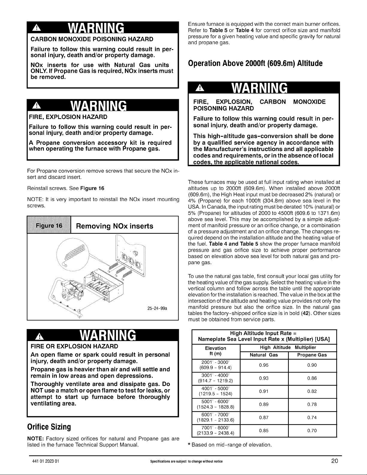
CARBON MONOXIDE POISONING HAZARD
Failure to follow this warning could result in per-
sonal injury, death and/or property damage.
NOx inserts for use with Natural Gas units
ONLY. If Propane Gas is required, NOx inserts must
be removed.
FIRE, EXPLOSION HAZARD
Failure to follow this warning could result in per-
sonal injury, death and/or property damage.
A Propane conversion accessory kit is required
when operating the furnace with Propane gas.
For Propane conversion remove screws that secure the NOx in-
sert and discard insert.
Reinstall screws. See Figure 16
NOTE: It is very important to reinstall the NOx insert mounting
screws.
;i;'iii
Removing NOx inserts
iiiiiiiiiiiiiiiiiiiiiiiiiiiiiiiiiiiiiiiiiiiiiiiiiiiiiiiiiiiiiiiiiiiiiiiiiiiiiiiiiiiiiiiiiiiiiiiiiiiiiiiiiiiiiiiiiiiiiiiiiiiiiiiiiiiiiiiiiiiiiiiiiiii
Ensure furnace is equipped with the correct main burner orifices.
Refer to Table 5 or Table 4 for correct orifice size and manifold
pressure for a given heating value and specific gravity for natural
and propane gas.
OperationAbove2000ft (609.6m)Altitude
FIRE, EXPLOSION, CARBON MONOXIDE
POISONING HAZARD
Failure to follow this warning could result in per-
sonal injury, death and/or property damage.
This high-altitude gas-conversion shall be done
by a qualified service agency in accordance with
the Manufacturer's instructions and all applicable
codes and requirements, or in the absence of local
codes Tthe applicable national codes.
These furnaces may be used at full input rating when installed at
altitudes up to 2000ft (609.6m). When installed above 2000ft
(609.6m), the High Heat input must be decreased 2% (natural) or
4% (Propane) for each 1000ft (304.8m) above sea level in the
USA. In Canada, the input rating must be derated 10% (natural) or
5% (Propane) for altitudes of 2000 to 4500ft (609.6 to 1371.6m)
above sea level. This may be accomplished by a simple adjust-
ment of manifold pressure or an orifice change, or a combination
of a pressure adjustment and an orifice change. The changes re-
quired depend on the installation altitude and the heating value of
the fuel. Table 4 and Table 5 show the proper furnace manifold
pressure and gas orifice size to achieve proper performance
based on elevation above sea level for both natural gas and pro-
pane gas.
25-24-99a
FIRE OR EXPLOSION HAZARD
An open flame or spark could result in personal
injury, death and/or property damage.
Propane gas is heavier than air and will settle and
remain in low areas and open depressions.
Thoroughly ventilate area and dissipate gas. Do
NOT use a match or open flame to test for leaks, or
attempt to start up furnace before thoroughly
ventilating area.
OrificeSizing
NOTE: Factory sized orifices for natural and Propane gas are
listed in the furnace Technical Support Manual.
To use the natural gas table, first consult your local gas utility for
the heating value of the gas supply. Select the heating value in the
vertical column and follow across the table until the appropriate
elevation for the installation is reached. The value in the box atthe
intersection of the altitude and heating value provides not only the
manifold pressure but also the orifice size. In the natural gas
tables the factory-shipped orifice size is in bold (42). Other sizes
must be obtained from service parts.
High Altitude Input Rate =
Nameplate Sea Level Input Rate x (Multiplier) [USA]
High Altitude MultiplierElevation
ft (m)
2001' - 3000'
(609.9 - 914.4)
3001' - 40OO'
(914.7 - 1219.2)
4001' - 5000'
(1219.5- 1524)
5001' - 6000'
(1524.3- 1828.8)
6001' - 7000'
(1829.1 - 2133.6) 0.87 0.74
7001' - 8000'
(2133.9 - 2438.4) 0.85 0.70
* Based on mid-range of elevation.
Natural Gas Propane Gas
0.95 0.90
0.93 0.86
0.91 0.82
O.89 O.78
44101 202301 Specifications are subject to change without notice 20
Page 21

MANIFOLDPRESSUREANDORIFICESIZE FORHIGHALTITUDEAPPLICATIONS
NATURAL GAS MANIFOLD PRESSURE (in wc)
iiiiiiiiiiiiiiiiiiiiiiiiiiiiiiiiiiiiiiiiiiiiiiiiiiiiiiiiiiiiiiiiiiiiiiiiiiiiiiiiiiii....
HEATING
VALUEat
ALTITUDE
BTU/CU.
FT,
700
725
750
775
0to2000 2001to3000 3001to4000 4001to5000 5001to6000 6001to7000
(0to609.6) (609.9to914.4) (914.7to1219.2) (1219.5to1524) (1524.3to1828.8) (1829.1to2133.6)
Orifice Mnfld Pres- Orifice MnfldPressure Orifice MnfldPressure Orifice Mnfld Pressure Orifice Mnfld Pressure Orifice Mnfld Pres-
No. sure No. No. No. No. No. sure
HI LO HI LO HI LO HI LO HI LO HI LO
_ = _- _ = ,_ := = _ i.:_= . 41 3.7 1.8
:-_ , _: , _ i..- _ _ i,;::4 .. _ 41 3.5 1.7 42 3.6 1.7
800
825
850
875
900
925
950
975
1000
1050
1100
41 3.7 1.8 42 3.5 1.7 42 3.3 1.6 43 3.7 1.8 43 3.4 1.7 43 3.1 1.5 44 3.3 1.6
41 3.5 1.7 42 3.3 1.6 42 3.1 1.5 43 3.5 1.7 43 3.2 1.6 44 3.4 1.7 44 3.1 1.5
42 3.7 1.8 42 3.2 1.6 43 3.6 1.8 43 3.3 1.6 44 3.5 1.7 44 3.2 1.6 45 3.6 1.7
42 3.5 1.7 43 3.7 1.8 43 3.4 1.7 43 3.1 1.5 44 3.3 1.6 45 3.7 1.8 45 3.4 1.7
42 3.2 1.6 43 3.3 1.6 43 3.1 1.5 44 3.3 1.6 45 3.6 1.8
43 3.6 1.7 44 3.5 1.7 44 3.2 1.6 45 3.6 1.8
41 3.6 1.7 42 3.6 1.8 42 3.4 1.6 42 3.1 1.5 43 3.5 1.7 43 3.2 1.6
42 3.7 1.8 42 3.4 1.7 42 3.2 1.6 43 3.6 1.7 43 3.3 1.6 44 3.5 1.7
Conversion:1inwc=249Pa
NOTE: Natural gas data is based on 0.60 specific gravity. For fuels with different specific gravity consult the National Fuel Gas Code ANSI
Z223.1-2006/NFPA 54-2006 or National Standard of Canada, Natural GasAnd Propane Installation Code CSA B149.1-05.
* In the USA, derating of these furnaces at 2% (Natural Gas) and 4% (Propane Gas) has been tested and design-certified by CSA.
In Canada, the input rating must be derated 5% (Natural Gas) and 10% (Propane Gas) for altitudes of 2,000 to 4,500 (609.6 to
1371.6m) above sea level. Use the 2001 to 3000 (609.9 to 914.4m) column in Table 4 and Table 5.
The burner orifice part nos. are as follows: HighAltitudeAir PressureSwitch
Orifice #41 1096942 Orifice #42 1011351
Orifice #43 1011377 Orifice #44 1011352 The factory-installed pressure switches need NOT be changed
Orifice #45 1011353 Orifice #54 1011376 for any furnace installations from sea level up to and including
Orifice #55 1011354 Orifice #56 1011355 8,000' (24.8.4 m) altitude.
MEAN ELEVATIONFEET ABOVE SEA LEVEL if(m)
7001to 8000
(2133.9to 2438.4)
Orifice MnfldPres-
No. sure
HI LO
_ :=- = 41 3.7 1.8 41 3.4 1.7
41 3.6 1.7 42 3.6 1.8 42 3.3 1.6
41 3.6 1.8 42 3.7 1.8 42 3.4 1.7 42 3.1 1.5
41 3.7 1.8 41 3.4 1.7 42 3.5 1.7 42 3.2 1.6 43 3.6 1.8
41 3.5 1.7 42 3.6 1.7 42 3.3 1.6 43 3.7 1.8 43 3.4 1.7
PROPANE GAS MANIFOLD PRESSURE (in wc)
MEAN ELEVATIONFEET ABOVE SEA LEVEL if(m)
HEATINGVALUE 0to 2000 2001to3000 3001to4000 4001to5000 5001to6000 6001to7000 7001to 8000
at ALTITUDE (0to609.6) (609.9to914.4) (914.7to1219.2) (1219.5to1524) (1524.3to1828.8) (1829.1to2133.6) (2133.9to2438.4)
BTU/CU. FT.
2500 10.0 4.9 10.0 4.9 9.0 4.4 10.0 4.9 9.4 4.6 8.5 4.2 10 4.9
"'1"° "'1.o .,1.o.,1.o.,1.o.,1.o.,1.o
Orifice Size #54 #54 #54 #55 #55 #55 #56
Conversion:1inwc=249Pa
NOTE: Propane data is based on 1.53 specific gravity. For fuels with different specific gravity consult the National Fuel Gas Code ANSI
Z223.1-2006/NFPA 54-2006 or National Standard OfCanada, Natural GasAnd Propane Installation Code CSA B149.1-05.
* In the USA, derating of these furnaces at 2% (Natural Gas) and 4% (Propane Gas) has been tested and design-certified by CSA.
In Canada, the input rating must be derated 5% (Natural Gas) and 10% (Propane Gas) for altitudes of 2,000 to 4,500 (609.6 to
1371.6m) above sea level. Use the 2001 to 3000 (609.9 to 914.4m) column in Table 4 and Table 5.
Changing Orifices
FIRE, EXPLOSION, CARBON MONOXIDE
POISONING HAZARD
Failure to follow this warning could result in per-
sonal injury, death and/or property damage.
This high-altitude gas-conversion shall be done
by a qualified service agency in accordance with
the Manufacturer's instructions and all applicable
codes and requirements, or in the absence of local
codes, the applicable national codes.
21 Specifications are subject to change without notice 44101 202301
1,
After disconnecting power and gas supply to the furnace,
remove the burner compartment door, exposing the burner
compartment.
2,
Disconnect gas line from gas valve so manifold can be re-
moved.
3,
Disconnect wiring at gas valve. Be sure to note the proper
location of all electrical wiring before being disconnected.
4,
Remove the four (4) screws holding the manifold and gas
valve to the manifold supports. Do not discard any screws.
See Figure 17.
Page 22

Manifold
FinalGas PipingCheck
FIRE OR EXPLOSION HAZARD
Failure to follow this warning could result in
personal injury and/or death.
Never test for gas leaks with an open flame. Use a
commercially available soap solution made
specifically for the detection of leaks to check all
connections.
5. Carefully remove the manifold assembly.
6. Remove the orifices from the manifold and replace them
with proper sized orifices. See Figure 18.
7. Tighten orifices so they are seated and gas tight. See
Figure 18.
8. Reassemble all parts in reverse order as removed. Be sure
to engage the main burner orifices inthe proper openings in
the burners.
9. After reassembling, turn gas on and check all joints for gas
leaks using a soapy solution. All leaks must be repaired im-
mediately.
Changing Orifices
iiiiiiiiiiiiiiiiiiiiiiiiiiiiiiiiiiiiiiiiiiiiiiiiiiiiiiiiiiiiiiiiiiiiiiiiiiiiiiiiiiiiiiiiiiiiiiiiiiiiiiiiiiiiiiiiiiiiiiiiiiiiiiiiiiiiiiiiiiiiiiii
Measurefrom face of orifice
RISQUE D'EXPLOSION ET D'INCENDIE
Le fait de ne pas suivre cet avertissement pourrait
entrainer des dommages corporels et / ou la mort.
Ne jamais examiner pour les fuites de gaz avec une
flamme vive. Utilisez plut6t un savon fait
specifiquement pour la detection des fuites de gaz
)our verifier tous les connections.
1,
The furnace and the equipment shut off valve must be dis-
connected from the gas supply piping system during any
pressure testing of that system at test pressures in excess
of 1/2" PSIG (3.5 Pa). Close the manual shut-off valve be-
fore testing at such pressures.
2,
The furnace must be isolated from the gas supply system
by closing the equipment shut off valve during any pressure
testing of the gas supply system at test pressure equal to or
less than 1/2" PSI (3.5 Pa).
3,
When installation is complete, test all pipe connections for
leaks with the gas pressure less than 1/2" PSlG (3.5 Pa) to
the gas valve.
4,
Apply a commercial soap solution to all joints to test for
leaks. Correct any leaks indicated by bubbles.
Correct even the smallest leak at once.
5.
6.
Check for leaks at gas valve and orifice connections to the
burner manifold along with the pilot tube connections to the
valve and pilot assembly while the furnace is operating.
9. Electrical Wiring
Field wiring connections must be made inside the furnace connec-
tion box. A suitable strain relief should be used at the point the
ELECTRICAL SHOCK HAZARD
Failure to turn off power could result in personal
injury or death.
Turn OFF electrical power at fuse box or service
panel before making any electrical connections
and ensure a proper ground connection is made
before connecting line voltage.
PowerSupplyWiring
The furnace MUST be electrically wired and grounded in accor-
dance with local codes, or inthe absence of local codes, with the
National Electrical Code (NEC), NFPA 70-2008 inthe U.S., or the
Canadian Electrical Code (CEC), CSA C22.1 in Canada.
The power supply to the furnace connections must be between
104 VAC and 127 VAC during furnace operation for acceptable
performance.
44101 202301 Specifications are subject to change without notice 22
wires exit the furnace casing.
Copper conductors shall be used. Line voltage wires should
conform to temperature limitation of 35° C rise. Wire and circuit
breaker sizing shall be based on the ampacity ofthe furnace elec-
trical components plus the amps for all installed accessories (1.0
amps total for EAC and HUM). Ampacity can be determined by us-
ing the NEC or CEC.
NOTE: Furnace will not have normal operation is line polarity is
reversed. Check ALL field and control connections prior to opera-
tion.
Furnace must be installed so the electrical components are pro-
tected from water and connected to its own separate circuit.
JunctionBox (J-Box)Relocation
The J-Box is installed in the burner compartment on left side of
casing. An alternate J-Box location on right side can be used.
1. Remove and save two screws holding J-Box to casing.
Page 23

2. Move large hole plug from right to left J-Box location.
3. Clip wire tie holding J-Box wires if needed.
4. Move J-Box to alternate location and attach using two
screws removed from left side location.
5. Position all wires away from hot surfaces, sharp edges, and
moving parts. Do not pinch J-Box wires or other wires when
reinstalling burner compartment door.
Thermostat
Heating
The two-stage furnace control board wilt operate with either a
single stage or a two-stage heating thermostat and wilt provide
two-stage heating operation.
For single-stage thermostat installations, the R and W wires
from the thermostat connect to the R and Wl connections on the
furnace control board.
Note: The TT (Thermostat Type) SW1 DIP switch # 3 should be in
the off position for the furnace to operate properly with a single-
stage thermostat. Failure to change DIP switch with single-stage
thermostat wilt result in Low Heat operation ONLY. (See
Figure 21 and wiring diagram)
During operation, the furnace will operate on tow Heat for up to12
minutes. If the heat request exists for more than 12 minutes, the
furnace wilt automatically shift to the high Heat mode for the re-
maining duration of the heating cycle.
For two-stage thermostat installations, the R, Wl and W2 wires
from the thermostat connect to the R, Wl and W2 connections on
the furnace control board. Set TT SW1 DIP switch #3 to ON posi-
tion. During operation, the furnace will shift from Low Heat to High
Heat as requested by the thermostat. (See Figure 19, Figure 20
and wiring diagram)
Heat anticipator setting will need to be measured if 24VAC humidi-
fier is installed. Measure current in series from Rto Wl at the ther-
mostat. Be sure 24VAC humidifier is wired up to control. Allow
furnace to operate for two minutes before recording the AC am-
perage reading. Set anticipator on thermostat to recorded value.
Thermostat location has an important effect on the operation of
the furnace. Follow instructions included with thermostat for cor-
rect mounting and wiring.
Low voltage connections to furnace must be made on terminal
board to furnace control board. (See Figure 19 and Figure 20)
Cooling
*8MPT
If cooling is used, the Y and G from the thermostat must be con-
nected to the control board Y/Y2 and G to energize cooling blower
speed.
NOTE: MPT models are not two-stage cooling compatible.
*8MPV
If single-stage cooling is used, the Y and G from the thermostat
must be connected to the control board Y/Y2 and G to energize
cooling blower speed.
Iftwo-stage cooling is used, the Y1, Y2, G off the thermostat must
be connected to Y1 of the tap select interface board for Low Cool-
ing, Y/Y2 of the furnace control board for High Cooling and G ofthe
furnace control board for continuous fan speed.
Optional Equipment
All wiring from furnace to optional equipment MUST conform to
local codes or, inthe absence of local codes with the latest edition
of The National Electric Code, NFPA 70 and/or The Canadian
Electric Code CSA C22.1. Install wiring in accordance with
manufacturer's instructions. The wiring MUST have a minimum
temperature rating of 105° C.
Humidifier/Electronic Air Cleaner
The furnace is wired for humidifier and/or electronic air cleaner
connection.
HUMIDIFIER - The HUM (24V) terminal is energized when
the tow pressure switch closes on a call for heat. The HUM
(115V) is energized when the inducer is energized.
ELECTRONICAIR CLEANER - EAC is energized when there
is a blower speed call, except it is NOT energized when blower
operates in the hard-wired continuous fan mode.
REDUCED FURNACE LIFE HAZARD
Failure to follow caution instructions may result in
reduced furnace life.
Do NOT exceed 115V/1.0 amp. maximum current
load for both the EAC terminal and the HUM
terminal combined.
Furnace Control Board
The furnace control board has a fixed blower ON delay of 30
seconds for High Heat calls and 45 seconds for Low Heat calls.
The blower OFF timing is factory preset at 140 seconds. If desired,
the fan OFF delay can be reset to obtain the longest delay times
while still maintaining comfort levels. See "Furnace Wiring
Diagram".
Dehumidification- Variable Speed ONLY (*8MPV)
The furnace control board has a dehumidification feature which
reduces cooling airflow by 20% when the DEHUM terminal [1/4"
(6.4mm) male quick connect] is energized by 24VAC and there is a
cooling call. DEHUM may be operated by athermostat dehumidify
(24VAC for dehumidify) command or a dehumidistat (switch
closes on call for dehumidification) with one terminal connected to
(Y1 for two-stage cooling or Y/Y2 for single-speed cooling
applications) and the other terminal connected to DEHUM
23 Specifications are subject to change without notice 44101 202301
Page 24

Electrical Connections
*8MPV
NOTE:Junction Boxcan be mountedto eitherthe left or right side.
115M 60 Hz.
Ground
I LowVoltage
ITerminalBoard
I
I I
i
I r
_ SingleStage
Thermostat
LowVoltage
TerminalBoard
.......
I
I
_ TwoStage '
TheLmostat jI
Motor
Control
J
NOTE:115VAC/60Hz,/single-phase
Operatingvoltagerange*:127VACmax,104VACrain,
* Permissiblelimitsofvoltageatwhichunitwill operatesatisfactorily
Electrical Connections
*8MPT
NOTE:Junction Box canbe mountedto eitherthe left or right side.
115M 60 Hz.
Variable Speed
Motor
25-25-06
Control Connections
Furnace Control Fuse
The 24V circuit contains a 5-amp, automotive-type fuse located
on furnace control board. (See Figure 21) Any electrical shorts to
24V wiring during installation, service, or maintenance may cause
fuse to blow. If fuse replacement is required, use only a fuse of
identical size (5 amp.).
TapSelectInterfaceBoard(*8MPV)
The Tap Select Interface Board is used with the Variable Speed
motor. There are DIP switches (SW2) for continuous blower
adjust, heating blower adjust, cooling blower adjust and cooling
on/off delay profiles. There is a jumper (J1) for slight blower
adjustment, increase (+)/no change (NOM)/decrease (-). There is
a jumper (J2) for airflow selection of Heat Pump EFFICIENCY or
COMFORT. (EFFICIENCY provides no airflow reduction in airflow
whether O is energized or not. COMFORT provides a 10%
reduction in airflow when O is not energized with a cooling call).
The O terminal is available for use for Heat Pump applications, if
desired.
The Y1 terminal (if atwo-stage Air Conditioner or two-stage Heat
Pump is used) will provide low cooling blower speed when
energized. (Only Y/Y2 on the furnace control board is used if a
single-stage Air Conditioner or Heat Pump is installed)
25-25-06a
NOTE:115VAC/60Hz,/single-phase
Operatingvoltagerange*:127VACmax,104VACrain,
* Permissiblelimitsofvoltageatwhichunitwill operatesatisfactorily
44101 202301 Specifications are subject to change without notice 24
Page 25

10. Ductwork and Filter (Upflow/Horizontal)
DuctInstallationRequirements
CARBON MONOXIDE POISONING HAZARD
Failure to properly seal duct could result in
personal injury or death.
Do NOT draw return air from inside a closet or utility
room where furnace is located. Return air duct
MUST be sealed to furnace casing.
Duct Connections
This furnace may be installed in only a bottom or side return ap-
plication. Return air through the back of the furnace is NOT al-
lowed.
Side connections can be made by cutting out the embossed area
shown in Figure 22. A plugged hole is provided at each furnace
side duct location to help start cutting the opening.
Cutting Side Return Air Opening
iiiiiiiiiiiiiiiiiiiiiiiiiiiiiiiiiiiiiiiiiiiiiiiiiiiiiiiiiiiiiiiiiiiiiiiiiiiiiiiiiiiiiiiiiiiiiiiiiiiiiiiiiiiiiiiiiiiiiiiiiiiiiiiiiiii
Knockout
Starting
Hole
When afurnace is installed so that supply ducts carry air cir-
culated by the furnace to areas outside of the space con-
taining the furnace, the return air shall also be handled by
duct(s) sealed to the furnace casing and terminating out-
side the space containing the furnace.
CARBON MONOXIDE POISONING HAZARD
Failure to follow this warning could result in
personal injury or death.
Cool air passing over heat exchanger could cause
condensate to form resulting in heat exchanger
failure.
When the furnace is used with a cooling unit, the furnace
shall be installed parallel with or on the upstream side of the
cooling unit to avoid condensation in the heating element.
With a parallel flow arrangement, the dampers or other
means used to control flow of air shall be adequate to pre-
vent chilled air from entering the furnace. Chilled air going
through the furnace could cause condensation and shorten
furnace life. Dampers (purchased locally) can be either au-
tomatic or manual. Manually or automatically operated
dampers MUST be equipped with a means to prevent fur-
nace and air conditioning operation, unless damper is in the
full heat or coot position.
Installation of locking-type dampers is recommended in all
branches, or in individual ducts to balance system's air
flows.
Non-combustible, flexible duct connectors are recom-
mended for return and supply connections to furnace.
If air return grille is located close to the fan inlet, install at
least one 90° air turn between fan and inlet grille to reduce
noise.
Bottom returns can be made by removing the knockout panel in
the furnace base. Do NOT remove knock-out except for a bottom
return.
DuctDesign
Design and install air distribution system to comply with Air Condi-
tioning Contractors of America manuals or other approved meth-
ods that conform to local codes and good trade practices.
When the furnace is located in an area near or adjacent to the liv-
ing area, the system should be carefully designed with returns to
minimize noise transmission through the return air grille. Any
blower moving a high volume of air will produce audible noise
which could be objectionable when the furnace is located very
close to a living area. It is often advisable to route the return air
ducts under the floor or through the attic.
• Ductwork installed in attic or exposed to outside tempera-
tures requires a minimum of 2" (50.8mm) of insulation with
outdoor type vapor barrier.
• Ductwork installed in an indoor unconditioned space re-
quires a minimum of 1" (25.4mm) of insulation with indoor
type vapor barrier.
Inspection Panel onsome models
For a furnace not equipped with a cooling coil, the outlet duct shall
be provided with a removable access panel. This opening shall be
accessible when the furnace isinstalled and shall be ofsuch a size
that the heat exchanger can be viewed for possible openings us-
ing light assistance or a probe can be inserted for sampling the air
stream. This access cover shall be attached in such a manner as
to prevent air leaks.
Filters
• Refer to furnace Technical Support Manual (Blower Data)
for air flow information.
• Size ductwork to handle air flow for heating and air condi- Filters are supplied with these furnaces, and additional filters may
tioning, be purchased from your distributor.
25 Specifications are subject to change without notice 44101 202301
A filter MUST be used.
Page 26

See Table 6 for required high-velocity filter sizes.
High Velocity Air Filter Sizes (max.600 FPM)
Internal
Cabinet Filter External Filter Rack
Width in(mm)
in (mm)
151/2 14X25 14X25 14 X 25 (355.6 x 635)
(393.7) (355.6 x 635) (355.6 x 635) or 16 X 25 (508 x 635)*
Bottom Bottom Side+
191/8 16X 25 * 16X 25 16 X 25
(485.8) (406.4x 635) * (406.4 x 635)* (406.4x 635)*
223/4 20 X 25 20 X 25 16 X 25
(577.9) (508 x 635)* (508x 635)* (508 x 635)*
* Greater than 1600 CFM with a maximum of 2000 CFM requires both (left and right)
side return filter racks or for single return in an upflow application, must use filter rack
NAHA001TK. See Figure 23.
+ Side return air duct(s) is not permitted with horizontal or downflow furnace installa-
tion.
Use either filter type:
• Washable, high-velocity filters are based on a maximum air
flow rating of 600 FPM.
• Disposable, low velocity filters are based on a maximum air
flow of 300 FPM when used with with external filter grille.
REDUCED FURNACE LIFE HAZARD
Failure to follow caution instructions may result in
reduced furnace life.
Use of excessively dirty and/or restrictive air filters
may increase furnace operating
temperatures and shorten the life of the furnace.
Filters supplied with the furnace are rated at a
maximum of 600 fpm air velocity and sized for the
furnace's airflow rate. Replacement filters must be
of equivalent type, size, and rating except as
described below.
Disposable, low-velocity filters may be used to
replace washable, high-velocity filters, providing
they are sized for 300 FPM or less.
NOTE: Disposable, low-velocity filters may be replaced with
washable, high-velocity filters providing they meet the minimum
size areas for 300 FPM or less. Washable, high-velocity filters
can be replaced ONLY with same type and size filter.
ii _)}i i
Optional Duct Standoff-
NAHA001TK in(mm)
_i i2o
_o8
18_2
(470) i
20 x 25 (508
Optional Filter Rack
(175)
Filter
FiltersRackInstallation
Side Return
Center the filter rack on the side panel, flush with the bottom edge
of the furnace. Mark the fastening holes. Drill the fastening holes
in the side panel and fasten the filter rack in place with sheet metal
screws. See Figure 24 & Figure 25.
iii i ii:: _
The furnaces with 1600 or less CFM rating are supplied
with a 16" x 25" (406 x 635mm) high-velocity filter and
rack. On these models the supplied filter may be installed
internally for bottom return or the supplied filter and rack
may be mounted externally for bottom return.
The furnaces with greater than 1600 CFM to 2000 CFM
may require that bottom return or both (left and right) side
Filter
25-23-05-1
Filters Installed on Two Sides
returns are used or for single side return in upflow applica-
tion, must use filter rack NAHA001TK. Two side return fil-
ters and racks are required. Filter racks must be mounted
UsingTwo
FilterRacks
externally. (See Figure 23 and Figure 24.) If return air
must be on one side only, an optional 20" x 25" (508 x
635mm) filter standoff rack kit can be used. (See
Figure 23.) For bottom return, an internal filter can be used
or a filter rack kit can be mounted externally.
See Technical Manual, Circulation Air Blower Data for addi-
tional information.
NOTE: The 20" x 25" (508 x 635mm) standoff side filter rack
gives more filter area but does not provide more air. (See
Figure 23.) To achieve 2000 CFM 2side returns may be required.
(See Figure 25.)
44101 202301 Specifications are subject to change without notice 26
\
Filter
Filter
25-23-05-3
Page 27

Internal Filterin Bottom ReturnInstallation
When installing _bottom-mounted filter inside the furnace, install
the filter clips on the edge of the bottom duct opening with the wid-
er end of the clips toward the blower, as shown in Figure 26. Clips
may be obtained from your distributor or fabricated from sheet
metal (Figure 27). Insert filter into side clips first and push filter
back until it is fully engaged into back clip.
Bottom Mounted Filter
CenterClip ,/
side to side _
Filter Clip Construction in(mm)
Note: If filters are only suitable for heating application, advise
homeowner that filter size may need to be increased if air condi-
tioning is added.
Addition OfAir Conditioning
When a refrigeration coil is used in conjunction with this furnace, it
must be installed on the discharge side of the furnace to avoid
condensation on the heat exchanger. All furnaces are designed
with a break-away duct flange on the supply air side of the fur-
nace. This allows for installation in the horizontal right or downflow
applications. The coil installation instructions must be consulted
for proper colt location and installation procedures. With a parallel
flow arrangement, dampers must be installed to prevent chilled air
from entering the furnace. If manually operated dampers are
used, they must be equipped with ameans to prevent operation of
either unit unless the damper is in full heat or full cool position.
Copper or plastic tubing may be used for the condensate drain
line.
_._'(38.1) _ --.. . _,,
\\\ -\\\\ ;J _7t2)
\>\ \ J T
26 Ga.Galvanized Steel "_.\
FASTpart number1008482 _'\_,/ 11/16" (27)
11. Ductwork and Filter (Downflow)
CARBON MONOXIDE POISONING HAZARD
Failure to properly seal duct could result in
personal injury or death.
Do NOT draw return air from inside a closet or utility
room where furnace is located. Return air duct
MUST be sealed to furnace casing.
FIRE HAZARD
Side return air duct(s) could cause excessive
furnace and/or air temperatures, which could
result in personal injury, death and/or property
damage.
Return air duct is to be connected to only the top of
downflow furnace.
BURN HAZARD
Failure to properly install vent shield could result in
personal injury or death.
The vent may be hot.
Vent Shield
A vent shield is required for all downflow installations. The vent
Must exit out the side of the furnace for all downflow installations.
This places the hot vent pipe (over 300°F) within reach of children.
The vent shield attaches to side of furnace to cover vent pipe. See
Figure 4 in "Installation" section.
Outlet Duct Flange
Downflow installations with cased coils require the furnace outlet
duct flange to be bent outward and flat to mate the outlet of the fur-
nace to the cased coil.
27 Specifications are subject to change without notice 44101202301
Page 28

FIRE HAZARD
Failure to install furnace on noncombustible
subbase could result in personal injury, death
and/or property damage.
Place furnace on noncombustible subbase on
downflow applications, unless installing on
non-combustible flooring.
Sub-Bases for Combustible Floors- Furnace Only
Note: When using the subbase for combustible floors, the dis-
charge air duct flanges on the furnace MUST be broken down to
provide proper fit up to the subbase. Use duct pliers to bend the
duct flanges flat onto the furnace casing. DO NOT bend the duct
flanges inward (toward the heat exchangers) as air flow restric-
tions may occur.
Sub-bases for Combustible Floors Dimensions in(mm)
Sub-base for
Combustible Floors
Part Number H*
Subbase for Furnace Only
NAHH001SB
NAHH002SB
NAHH003SB
Subbasefor Coil Box
NAHH004SB
NAHH005SB
NAHH006SB
OutsideDimension
** BaseSpacerSideToSide
23 (284.2)
Sub-base for Combustible
Floor Dimensions
J_
1511/16
(398.5)
195/16
(490.5)
221b/16
(582.6)
153/4
(25.4)
193/8
(181.1)
283/4(730.3)
283/4(730.3)
283/4 (730.3)
209/16
(522.3)
209/16
(522.3)
209/16
(522.3)
K _
149/16(369.9) 16(406.4)
183/16 (462) 16(406.4)
2113/16(554) 16(406.4)
149/16(369.9) (408)
183/16 (462) 161/16
2113/16(554) (408)
161/16
(4o8)
161/16
The Sub-base for Combustible Floors MUST be used when a
downflow furnace is set on a combustible floor, even when the fur-
nace is installed on a coil box.
1. Cut the opening in the floor according to the dimensions in
Table 7 because the base is equipped with locating tabs that
center the base over the opening.
The opening in the base is 11/4" (31.8mm) shorter and 11/8"
(28.6mm) narrower than the minimum required size of the
opening in the floor. This is done to maintain a 1" clearance
between the floor and the plenum.
2. Fabricate the plenum to the dimensions given in Table 7.
Note that the dimensions given are outside dimensions.
3. Set the base over the opening in the floor, centering the open-
ing in the base over the opening in the floor. Fasten the base
to the floor with screws or nails. See Figure 28 and
Figure 29.
4. Drop the plenum through the opening in the base. The flange
of the plenum should rest on top of the combustible floor
base.
Opening In Floor
N
161/4
(412.8)
161/4
(412.8)
161/4
(412.8)
161/4
(412.8)
161/4
(412.8)
161/4
(412.8)
145/8
(371.5)
181/4
(463.6)
21//8
(555.6)
145/8
(371.5)
181/4
(463.6)
21//8
(555.6)
Opening In
Base For Plenum
R
15(381)
15(381)
15(381)
15(381)
15(381)
15(381)
131/2
(342.9)
171/8
(435.6)
19_/4
(501.7)
131/2
(342.9)
171/8
(435.6)
19_/4
(501.7)
Typical Plenum
Dimensions
S T
15(381)
15(381)
15(381)
15(381)
15(381)
15(381)
131/2
(342.9)
171/8
(435.6)
19_/4
(501.7)
131/2
(342.9)
171/8
(435.6)
19_/4
(501.7)
i ii
: ; r_i_u_'=°; Furnace ONLY
iiiiiiiiiiiiiiiiiiiiiiiiiiiiiiiiiiiiiiiiiiiiiiiiiiiiiiiiiiiiiiiiiiiiiiiiiiiiiiiiiiiiiiiiiiiiiiiiiiiiiiiiiiiiiiiiiiiiiiiiiiiiiiiiiiiiiiiiiiiiiiiiiiii
Exploded View of Sub-Base for
z"_<3_r__ s A = 4 1/4" (108mm) Minimum
_1 .... _" clearance from back of hole
S_ Plenum _: to wall or other obstruction.
Sub-base for CombustibleFloors- Downflow Coil
Adapter Box
The sub-base for combustible floors is not required when a down-
flow furnace, used with a downflow coil box, is set on combus-
tible flooring.
1. Cut the opening in the floor according to the dimensions in
Table 7 because the base is equipped with locating tabs
that center the base over the opening.
The opening in the base is 11/4"(31.8mm) shorter and 11/8"
(28.6mm) narrower than the minimum required size of the
H_ _ 2" (50.8mm)
opening in the floor. This is done to maintain a 1" (25.4mm)
clearance between the floor and the plenum.
2" (50.8mm)__'_ 1" (25.4mm)
44101 202301 Specifications are subject to change without notice 28
Page 29

iiiM;_Miiii!iiiiiiii;iii!;jiIi_i;jiiii_iiii_iiii11iiiii_ji!!iiiiiIii1i!iijiiiiIi;1i!;ijiiii!i_iiiiIii1iiij};;;1iiii_!iii1iiii
Sett,n t.e ase
iiiiiiiiiiiiiiiiiiiiiiiiiiiiiiiiiiiiiiiiiiiiiiiiiiiiiiiiiiiiiiiiiiiiiiiiiiiiiiiiiiiiiiiiiiiiiiiiiiiiiiiiiiiiiiiiiiiiiiiiiiiiiiiiiiiiiiiiiiiiiiiiiiii
Furnace, /;- j \ z _.. ,
Subbase __
Insulation l i
'_, i
_-_ ;; _ WoodFloor
height of the subbase raises the downfiow coil off the floor to allow
easy installation of the condensate drain
Condensate Line Raised by Base
WoodScrew Plenum
25-20-46A
Non-Combustible Floor
2,
Fabricate the plenum to the dimensions given in Table 7.
Note that the dimensions given are outside dimensions.
3.
Set the base over the opening in the floor, centering the
opening in the base over the opening in the floor. Fasten
the base to the floor with screws or nails. See Figure 30
and Figure 31.
Set the furnace over the opening in the floor. If necessary, grout
around the base to seal air leaks between the base and the floor.
DuctConnections
Inthe downfiow position, the return-air duct must be connected to
only the top of the furnace. Top return connections can be made
by removing the knockout panel in the furnace base. Return air
Exploded View of Base for
iiiiiiiiiiiiiiiiiiiiiiiiiiiiiiiiiiiiiiiiiiiiiiiiiiiiiiiiiiiiiiiiiiiiiiiiiiiiiiiiiiiiiiiiiiiiiiiiiiiiiiiiiiiiiiiiiiiiiiiiiiiiiiiiiiiiiiiiiiiiiiiiiiii
Downflow Cased Coil
connection through the side(s) or back of the furnace is NOT al-
lowed.
DuctDesign
Design and install the air distribution system to comply with Air
Conditioning Contractors of America manuals or other approved
methods that conform to local codes and good trade practices.
When the furnace is located in an area near or adjacent to the liv-
ing area, the system should be carefully designed with returns to
minimize noise transmission through the return air grille. Any
blower moving a high volume of air wilt produce audible noise
which, could be objectionable when the furnace is located very
close to a living area. It is often advisable to route the return air
ducts under the floor or through the attic.
Refer to furnace Technical Support Manual (Blower Data)
for air flow information.
Size ductwork to handle air flow for heating and air condi-
tioning, if used.
Duct
Installation Requirements
When afurnace is installed so that supply ducts carry air cir-
culated by the furnace to areas outside of the space con-
taining the furnace, the return air shall also be handled by
duct(s) sealed to the furnace casing and terminating out-
side the space containing the furnace.
i J;;: J iJJ J; J i Ji;JJ
_:_i:iiiil Setting the Base
iiiiiiiiiiiiiiiiiiiiiiiiiiiiiiiiiiiiiiiiiiiiiiiiiiiiiiiiiiiiiiiiiiiiiiiiiiiiiiiiiiiiiiiiiiiiiiiiiiiiiiiiiiiiiiiiiiiiiiiiiiiiiiiiiiiiiiiiiiiiiiiiiiii
Coil
Subbase
Insulation
21/2" (63.5mm)
11/2" (38.1mm)
--_\_-_-/z 25-20-52
.........
CARBON MONOXIDE POISONING HAZARD
Failure to follow this warning could result in per-
sonal injury or death.
"_'_J_ i "_..'_'_ Wood Floor
Install cooling coil on furnace discharge. Cool air
passing over heat exchanger could cause
WoodScrew ' // // _'_ Plenum 25-20-46A
condensate to form resulting in heat exchanger
failure.
Consideration must be given to the height of the base to allow for
easy installation of the condensate drain. See Figure 32. This
subbase for combustible floors has been designed so that the
• When a furnace is used with a cooling unit, the furnace
shall be installed parallel with or on the upstream side of the
cooling unit to avoid condensation in the heating element.
29 Specifications are subject to change without notice 44101 202301
Page 30

• With a parallel flow arrangement, the dampers or other
means used to control flow of air shall be adequate to pre-
vent chilled air from entering the furnace. Chilled air going
through the furnace could cause condensation and shorten
furnace life. Dampers (purchased locally) can be either au-
tomatic or manual. Manually or automatically operated
dampers MUST be equipped with a means to prevent fur-
nace and air conditioning operation, unless damper is in
the full heat or cool position.
• Installation of locking-type dampers is recommended in all
branches, or in individual ducts to balance system's air
flows.
12. Checks and Adjustments
Startup
• Non-combustible, flexible duct connectors are recom-
mended for return and supply connections to furnace.
• If air return grille is located close to the fan inlet, install at
least one 90° air turn between fan and inlet grille to reduce
noise.
• Ductwork installed in attic or exposed to outside tempera-
tures requires a minimum of 2" (50.8mm) of insulation with
outdoor type vapor barrier.
• Ductwork installed in an indoor unconditioned space re-
quires a minimum of 1" (25.4mm) of insulation with indoor
type vapor barrier.
NOTE: Refer to startup procedures in the Users Information
Manual.
ELECTRICAL SHOCK, FIRE, OR EXPLOSION
HAZARD
Failure to followthis warning could result in injury,
death, and/or property damage.
If any sparks, odors or unusual noises occur,
immediately shut OFF gas and power to furnace.
Check for wiring errors or obstruction to blower.
GasSupply Pressure
Gas supply pressure should be within minimum and maximum
values listed on rating plate. Pressures are usually set by gas sup-
pliers.
ManifoldGasPressureAdjustments
(High and Low Heat)
NOTE: Make adjustment to manifold pressure with burners oper-
ating.
Typical Gas Control Valve Honeywell
Regulator
FIRE OR EXPLOSION HAZARD
Failure to turn OFF gas at shut off before
connecting manometer could result in personal
injury, death and/or property damage.
Turn OFF gas at shut off before connecting
manometer.
1. With gas OFF, connect manometer to manifold pressure
tap on the outlet of gas control valve. See Figure 33. Use a
manometer with a 0 to 12 in wc (0 to 2989 Pa) range.
2. Turn gas ON. Operate the furnace on High Heat by using a
jumper wire on the R to Wl & W2 thermostat connections
on the furnace control board.
3. Remove manifold pressure adjustment screw cover on fur-
nace gas control valve. Turn adjusting screw counterclock-
wise to decrease the manifold pressure and clockwise to
increase pressure. See Figure 33.
NOTE: Adjustment screw cover MUST be replaced on gas control
valve before reading manifold pressure and operating furnace.
4. Set manifold pressure to value shown in Table 5 or Table 4.
5. Operate the furnace on Low Heat by using a jumper wire on
the R to Wl thermostat connections on the furnace control
board.
Note: The SWl DIP switch #3 should be in the on position
to set the Low Heat manifold pressure. (See wiring dia-
gram.)
6. Repeat steps 3 and 4 for Low Heat operation.
7. When the manifold pressures are properly set, replace the
adjustment screw covers on the gas control valve.
8. Remove the jumper wires from the thermostat connections
on the furnace control board. Remove manometer connec-
tion from manifold pressure tap, and replace plug in gas
valve.
9. Return SWl DIP switch #3 to previous setting.
10. Check for leaks at plug.
Natural GasInput RatingCheck
The gas meter can be used to measure input to furnace. Check
with gas supplier for actual BTU content.
1. Turn OFF gas supply to all appliances other than furnace
and start furnace. Use jumper wire on R to Wl and W2 for
OUTLET
25-24-98a
44101 202301 Specifications are subject to change without notice 30
Pressure
Tap 1/8"
High Heat.
2. Time how many seconds it takes the smallest dial on the
gas meter to make one complete revolution. Refer to Ex-
ample.
Page 31
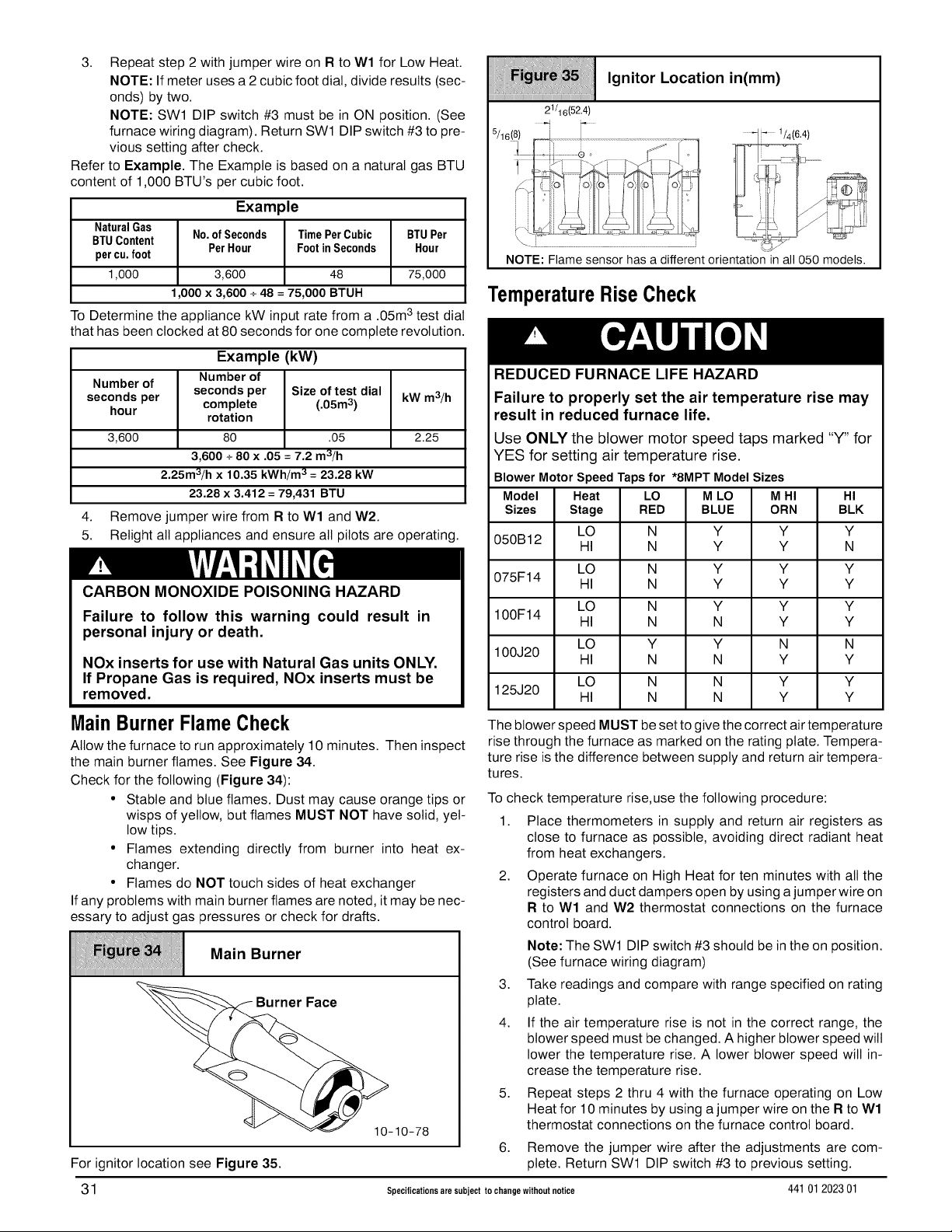
3. Repeat step 2 with jumper wire on R to Wl for Low Heat.
NOTE: If meter uses a 2 cubic foot dial, divide results (sec-
onds) by two.
NOTE: SWl DIP switch #3 must be in ON position. (See
furnace wiring diagram). Return SWl DIP switch #3 to pre-
vious setting after check.
Refer to Example. The Example is based on a natural gas BTU
content of 1,000 BTU's per cubic foot.
Example
NaturalGas
BTUContent
percu.foot
1,000
No.ofSeconds TimePerCubic
PerHour FootinSeconds
3,600 48
BTUPer
Hour
75,000
1,000x 3,600 + 48 = 75,000 BTUH
To Determine the appliance kW input rate from a .05m3 test dial
that has been clocked at 80 seconds for one complete revolution.
Example (kW)
Number of
seconds per
hour
3,600
Number of
seconds per Size of test dial
complete (.05m 3)
rotation
80 .05
3,600 + 80 x .05 = 7.2 m3/h
2.25m3/h x 10.35 kWh/m3 = 23.28 kW
23.28 X 3.412 = 79,431 BTU
kW m3/h
2.25
4. Remove jumper wire from R to Wl and W2.
5. Relight all appliances and ensure all pilots are operating.
CARBON MONOXIDE POISONING HAZARD
Failure to follow this warning could result in
personal injury or death.
NOx inserts for use with Natural Gas units ONLY.
If Propane Gas is required, NOx inserts must be
removed.
Ignitor Location in(mm)
21/16(52.4)
NOTE: Flame sensor has a different orientation in all 050 models.
TemperatureRiseCheck
REDUCED FURNACE LIFE HAZARD
Failure to properly set the air temperature rise may
result in reduced furnace life.
Use ONLY the blower motor speed taps marked "Y" for
YES for setting air temperature rise.
BlowerMotor SpeedTaps for *8MPT Model Sizes
Model Heat LO M LO M HI HI
Sizes Stage RED BLUE ORN BLK
050B12 HI N Y Y N
075F14 HI N Y Y Y
100F14 HI N N Y Y
100J20
125J20
LO N Y Y Y
LO N Y Y Y
LO N Y Y Y
LO Y Y N N
HI N N Y Y
LO N N Y Y
HI N N Y Y
MainBurnerFlameCheck
Allow the furnace to run approximately 10 minutes. Then inspect
the main burner flames. See Figure 34.
Check for the following (Figure 34):
• Stable and blue flames. Dust may cause orange tips or
wisps of yellow, but flames MUST NOT have solid, yel-
low tips.
• Flames extending directly from burner into heat ex-
changer.
• Flames do NOT touch sides of heat exchanger
If any problems with main burner flames are noted, it may be nec-
essary to adjust gas pressures or check for drafts.
The blower speed MUST be set to give the correct air temperature
rise through the furnace as marked on the rating plate. Tempera-
ture rise is the difference between supply and return air tempera-
tures.
To check temperature rise,use the following procedure:
1. Place thermometers in supply and return air registers as
close to furnace as possible, avoiding direct radiant heat
from heat exchangers.
2. Operate furnace on High Heat for ten minutes with all the
registers and duct dampers open by using a jumper wire on
R to Wl and W2 thermostat connections on the furnace
control board.
Note: The SWl DIP switch #3 should be in the on position.
iiiiiiiiiiiiiiiiiiiiiiiiiiiiiiiiiiiiiiiiiiiiiiiiiiiiiiiiiiiiiiiiiiiiiiiiiiiiiiiiiiiiiiiiiiiiiiiiiiiiiiiiiiiiiiiiiiiiiiiiiiiiiiiiiiiiiiiiiiiiiiiiiiii
(See furnace wiring diagram)
3. Take readings and compare with range specified on rating
plate.
4. If the air temperature rise is not in the correct range, the
r Face
blower speed must be changed. A higher blower speed will
lower the temperature rise. A lower blower speed will in-
crease the temperature rise.
5. Repeat steps 2 thru 4 with the furnace operating on Low
__ _-10-78
Heat for 10 minutes by using a jumper wire on the R to Wl
thermostat connections on the furnace control board.
6,
Remove the jumper wire after the adjustments are com-
For ignitor location see Figure 35.
plete. Return SWl DIP switch #3 to previous setting.
31 Specifications are subject to change without notice 44101 202301
Page 32

BlowerAdjustments(*SMPT)
ChangingBlower Speed
ELECTRICAL SHOCK HAZARD
Failure to follow this warning could result in
personal injury or death.
Turn OFF power to furnace before changing
speed taps.
Hard-Wired ContinuousFan
A terminal is provided on the furnace control board located in the
circulating air blower compartment for operation of the continuous
fan option. This connection isintended for the tow speed motor tap,
and has a lower contact rating (8 amps) than the heat and cool
taps. When the low speed blower lead is connected to this
terminal, it wilt provide low speed blower operation whenever the
other three speeds ("HI HEAT or LO HEAT" or COOL) are not
energized.
Thoroughly check the system after modification to ensure the
proper operation ofthe circulating air blower in all modes of opera-
tion.
NOTE: The speed taps that the manufacturer sets at the factory
for this furnace are based on a nominal 400 CFM per ton for cool-
ing and the basic mid range on the temperature rise for heating.
Since the manufacturer cannot predict the static pressure
that will be applied to the furnace, it is the responsibility of
the installer dealer/contractor to select the proper blower
motor speed leads for the application when the furnace is
installed.
If it is necessary to change speeds, refer to steps below.
1. Refer to Furnace Wiring Diagram for location of the heating
and cooling speed taps located on the furnace control board
as well as location of unused blower motor speed leads. Use
the chart (Table 8) to determine the blower motor speed set-
tings.
Wire Color
Black
Orange*
Blue
Red
* Med-High speed may not be provided on all models.
2,
Change the heat or coot blower motor speed by removing the
motor lead from the "HI HEAT or LO HEAT" or "COOL" termi-
nal and replace it with the desired motor speed lead from the
"MI" or "M2" location. Connect the wire previously removed
from the "HI HEAT or LO HEAT" or "COOL" terminal to the
vacated "M1" or "M2" terminal.
3,
Ifthe same speed must be used for both heating and cooling,
remove the undesired motor speed lead from the "HI HEAT
or LO HEAT" or "COOL" terminal and connect that lead to
the open terminal at "M1" or "M2" location or tape off. Attach
a jumper between the "HI HEAT or LO HEAT" and "COOL"
terminals and the remaining motor speed lead.
NOTE: When using the same speed on motors with (4) speed
leads, it will be necessary to tape offthe terminal of the motor
speed lead removed from the "HI HEAT or LO HEAT" or
"COOL" terminal with electrical tape since an open terminal
will not be available at the "M1" or "M2" location.
Motor Speed
High
Med-High
Med-Low
Low
Continuous- Fan using"G"
Energizing the "G" terminal on the furnace control board provides
continuous fan operation. This is done by connecting the G
terminal of the thermostat to the G terminal on the furnace control
board. When the FAN switch is turned from auto to ON the fan will
operate continuously at"LO HEAT" speed. EAC will be energized
in this mode.
NOTE: In heating, the fan will turn off during furnace ignition and
warm up then restart at heating speed.
Separate Speed Selections for Low Heat, High Heat,
Cool, and Continuous-Fan
Connect tow speed lead from circulating air motor to the "CONT"
terminal atthe furnace control board. The appropriate motor leads
should already be connected to the "HI HEAT and LO HEAT" and
"COOL" terminals.
Heating and Continuous-Fan Speed the Same
If it is necessary to operate the Low Heat speed and
continuous-fan speed using the same blower speed, connect a
jumper between the "LO HEAT" and "CONT FAN" terminals on
the furnace control board.
Note: There should be only ONE motor lead going to the "LO
HEAT" and "CONT FAN" terminals.
BlowerAdjustments(*SMPV)
Changing BlowerSpeed
ELECTRICAL SHOCK HAZARD
Failure to disconnect power could result in
personal injury or death.
Turn OFF power to furnace before changing blower
speed.
NOTE: The blower speeds that the manufacturer sets from the
factory for this product are based on a nominal 400 CFM per ton
cooling and the mid range on the temperature rise for heating.
Since the manufacturer cannot predict the static pressure
that will be applied to the furnace, it is the responsibility of the
installing dealer/contractor to select the proper speeds for
the application when the furnace is installed.
If it is necessary to change speeds, refer to steps below.
1. The 115 VAC power supply to the furnace must be turned
OFF before making adjustments to the motor.
NOTE: Allow at least 1 minute before restoring power to the
furnace after making Blower Control changes.
2,
The heating, cooling and continuous blower speeds can be
adjusted by changing the SW2 DIP switch settings that are
located on the Tap Select Interface Board (see Figure 36).
* Switches #1 and #2 adjust the continuous blower speeds.
Switches #3 and #4 adjust the heating speed.
Switches #5 and #6 adjust the cooling speed.
Switches #7 and #8 adjust the cooling speed on/off delay
profiles. See the "Technical Support Manual" for the switch
settings for the desired airflow rates for the installation.
The jumper J1 is used to slightly increase (+) or decrease
(-) or not change (NOM) the blower speed selected from
SW2. J1 effects BOTH cooling and heating airflow.
* Continuous blower selection DIP 10 and 11 will cause the
blower to run in high cooling speed for all low cooling (Y1)
calls. Continuous blower DIP settings of 00 and 01 will allow
low cooling (Y1) calls to operate normally.
44101 202301 Specifications are subject to change without notice 32
Page 33

Continuous- Fan using"G"
and DIP SW2 switch #2. EAC will beenergized in this mode.
Energizing the "G" terminal on the furnace control board provides
continuous fan operation. This is done by connecting the G
terminal of the thermostat to the G terminal on the furnace control
board. When the FAN switch is turned from auto to ON the fan wilt
operate continuously at airflow selected by DIP SW2 switch #1
Variable Speed (*8MPV) Tap Select Interface Board (TSIB)
iiiiiiiiiiiiiiiiiiiiiiiiiiiiiiiiiiiiiiiiiiiiiiiiiiiiiiiiiiiiiiiiiiiiiiiiiiiiiiiiiiiiiiiiiiiiiiiiiiiiiiiiiiiiiiiiiiiiiiiiiiiiiiiiiiiiiiiiiiiiiiiiiiii
• 0 0 0 •
iiiiAC?i_:lJo E_=
BRN C - YE [_1
_, I ............ I_1 l [] ............... _;
_oi_vnnnnnnnn_/_°_c°::°:z'°__
........O '___
___
ON = 1
NOTE: In heating, the fan will not turn off during furnace ignition
and warm up.
HardWired ContinuousFan Operation
Notavailablefor variablespeed models.
HP MODE SELECTION /
!r Ir
OFF = 0
CONTINUOUS
CFM SELECTI II _E_T'"_s_IIC°°L"°CF_IICOO'"_O_'OFFSELECT SELECT DELAY PROFILES
13. Furnace Maintenance
FIRE, EXPLOSION, OR CARBON MONOXIDE
POISONING HAZARD
Failure to have the furnace inspected and
maintained could result in personal injury, death,
and/or property damage.
It is recommended that the furnace be inspected
and serviced on an annual basis (before the
heating season) by a qualified service agency.
HEAT PUMP EFFICIENCY OR I
HP COMFORT SELECT ON I
I
I
25 25 54
ELECTRICAL SHOCK, FIRE OR EXPLOSION
HAZARD
Failure to follow this warning could result in
personal injury, death, and/or property damage.
• Before servicing, disconnect all electrical power
to furnace.
• When servicing controls, label all wires prior to
disconnecting. Reconnect wires correctly.
• Verify proper operation after servicing.
See "User's Information Manual".
33 Specifications are subject to change without notice 44101202301
Page 34

14. Sequence of Operation & Diagnostics for *8MPT
The following is the normal operating sequence at factory default settings (SWl OFF/ON/OFF)
Cooling(Y) Request:
24VAC signals applied to Y/Y2 & G terminals of FCB (furnace control board).
• Cool motor speed is energized after 5 second Cool Fan On Delay time.
Y/Y2 & G signals removed from FCB
• Coot motor speed is de-energized after 90 second Coot Fan Off Delay time.
NOTE: DEHUM not available on the *8MPT models.
ContinuousCirculatingFan(G) Request:
24VAC signal applied to G terminal of FCB.
• Low-Heat motor speed is energized without delay.
G signal removed from FCB.
• Low-Heat motor speed is de-energized after 5 second delay.
NOTE 1) Furnace de-energizes the fan during the heat exchanger warm-up period on a call for Heating that occurs during a G request
unless a blower motor lead is connected to the CONT FAN terminal on the FCB, inwhich case see NOTE 2)
NOTE 2) Heating or Cooling requests received during a Fan request cause the fan speed to change to the appropriate heat or cool speed
after the Fan On Delay time expires. The fan returns to continuous circulating speed after the selected Fan Off Delay time expires
following toss of the Heating or Cooling request.
ContinuousCirculatingFanHard-Wired(Cont) Request:
Field selected low speed motor tap installed on "CONT FAN" terminal.
• Low speed is energized when power applied to furnace. Operates at this speed continuously while there are no other
blower demands from furnace control board. Fan demands from furnace control board for heat, coot or"G" will override hard-wired
speed tap.
NOTE 3) EAC is NOT active for hard-wired mode but IS active for fan demands from furnace control board for heat, cool and "G".
Heating(Wl) Request(singlestagethermostatoperation,SWl DIPswitch#3 mustbe in OFF
position)(see furnacewiringdiagram):
24VAC signal applied to Wl terminal of FCB.
• Inducer motor turns on at high speed.
• Following a 15 second prepurge delay after the low pressure switch closes, the ignitor begins a 17 second warm up.
• The gas valve is energized, the main burners light at Low Heat rate and flame is sensed.
• The ignitor is de-energized, and the inducer drops to low speed after the main burners ignite.
• The FCB will delay Low Heat blower operation for the 45-second Low Heat Fan On Delay time, timed from
the opening of the gas valve.
• If the Wl request is still present after 12 minutes, timed from the opening of the gas valve, the inducer switches to high speed,
closing the high pressure switch, then the High Heat solenoid energizes, and the fan switches to High Heat speed.
W1 signal removed from FCB.
• The gas valve de-energizes and the main burners go out.
• The inducer runs at its present speed for a 15 second postpurge period.
• The fan runs at its present speed.
• The fan de-energizes after the selected Heat Fan Off Delay time expires, timed from the gas valve de-energizing.
NOTE 4) If anew Heating request arrives while the control iswaiting in the Heat Fan Off Delay time, the FCB will wait for the selected Heat
Fan Off Delay then start a new heating cycle as long as the heat call remains.
HeatingRequest(Wl & W2) (two-stagethermostatoperation,SWl DIPswitch#3 must be in ON
position) (see furnace wiring diagram):
24VAC signal applied to Wl terminal of FCB.
• Same response as single stage thermostat operation (fan uses Low Stage Heat On Delay) described above except the control
will not go to High Heat rate, and High Heat Fan speed unless a W2 signal is applied.
24VAC signal applied to Wl and W2 terminals of FCB.
• Same light-off routine as described for the signal stage thermostat operation except main burners light at High Heat rate, the
inducer remains on high speed after ignition, and the FCB will delay blower operation at the High Heat Fan speed for 30 second
On Delay time.
NOTE 5) The FCB responds without delay to the presence or loss of W2 (with W1 constant). W1 &W2 result in high inducer, High Heat
rate, and High Heat Fan speed. Wl only results in low inducer, Low Heat rate, and Low Heat Fan speed.
44101 202301 Specifications are subject to change without notice 34
Page 35

Heating Request with Gas Shut Off:
24 VAC signal applied to Wl terminal of FCB.
The FCB will attempt 4 cycles for ignition then go to soft lockout for 3 hours, and then try for ignition again as long as the heat call
remains. Power reset will clear lockout.
• Inducer motor turns on at high speed.
• Following a 15 second prepurge delay, the ignitor begins warm up.
• The ignitor glows red-hot for 22 seconds, then turns off. The FCB flashes error code 6.
• The ignitor
• The ignitor
• The ignitor
• The ignitor
• The ignitor
stays off for 17 seconds, then begins to warm up again.
glows red hot for 22 seconds then turns off. The FCB continues flashing error code 6.
stays off for 17 seconds, then begins to warm up again.
glows red hot for 22 seconds then turns off. The FCB continues flashing error code 6.
stays off for 17 seconds, then begins to warm up again.
The ignitor glows red hot for 22 seconds then turns off. The FCB proceeds to soft lockout. Stops flashing
error code 6, and begins flashing error code 6 + 1.
The inducer motor de-energizes after a 15 second post purge.
FurnaceControlBoardDiagnosticCodes (SeeFigure37):
OFF
Heartbeat
ON SOLID
1 Flash
2 Flashes =
3 Flashes =
4 Flashes =
5 Flashes =
6 Flashes =
6 + 1 Flashes =
7 Flashes =
8 Flashes =
9 Flashes =
10 Flashes =
NOTE: The 6 +
codes.
* Ifstatus code recall is needed, briefly (2-3 seconds) remove then
reconnect one limit switch wire (main or rollout) to display last
stored status code. Do not remove power or blower door before
initiating status code recall or code wilt be lost. Code is
automatically cleared after 72 hours or upon power reset.
* Properflame sense microamps: 0.7 microamps D.C. minimum,
2.0 - 4.0 microamps nominal
= 24VAC or 115VAC is off, fuse is open
= Normal operation or no previous Diagnostic Code
= Soft Lockout - Furnace Control Error (1 hr delay)
If code repeats immediately following power reset then replace control
= Not used
Pressure switch(es) closed when should be open
Low pressure switch open when should be closed
Limit or flame roll-out switch open (less than 2 minutes)
Flame sensed out of sequence
Failure to ignite or flame sense lost while running
Soft Lockout - Max of four trials for ignition reached (3hr delay)
Soft Lockout - Limit or flame roll-out switch open longer than 2 minutes (1 hr delay)
(roll-out switch requires manual reset)
Permanent Lockout - Gas valve relay contact stuck closed or miswired gas valve (power reset only)
High pressure switch open when should be closed
Line voltage polarity or improper transformer phasing on twinned applications
ii i: ii
1 designation indicates a combination of flash i __:
for switch se_tings _-_ t;( -.\\-%_ _.
Control Board
,,_ _%..._42J_
24VAC .......... _ , '
FUSE DEHUM
25-24-74
HUMIDIFIER - The 24VAC HUM is energized when the low pressure switch closes on a call for heat. The 115V HUM (called HUM on
Control) is energized when the inducer is energized.
ELECTRONIC AIR CLEANER - EAC is energized when there is a blower speed call. Itis NOT energized when blower operates in
the hard-wired continuous fan mode.
35 Specifications are subject to change without notice 44101 202301
Page 36

15. WiringDiagram*8MPT(TwoStageHeatingwith PSCMotor)
COOL ON DELAY: 5 SEC ]
I COOL OFF DELAY: 90 SEC
HiGH STAGE ]
I EAT ON DELAY 30 SEC. ]
I EAC + HUM 1.0A MAX
LOW STAGE I
HEAT ON DELAY 45 SEC. I
COMB NED
I
8
FURNACE CONTROL SWl HEAT OFF DELAY
SWl =1, SWl =2
_ 8 88 88 coz_
NEAT 0FF-DELAY HEAT 0FF-DELAY HEAT 0FF-DELAY H EAT 0FF-DELAY
THERMOSTAT TYPE THERMOSTAT TYPE THERMOSTAT TYPE THERMOSTAT TYPE
THERMOSTAT TYPE
SWI =3
HEAT 0FFDELAY
THERMOSTAT TYPE
CAPACH OR
44101 202301 Specifications are subject to change without notice 36
Page 37

16. Sequence of Operation & Diagnostics for *8MPV
The following is the normal operating sequence at factory default settings (SWl OFF/ON/OFF, SW2 all OFF)
NOTE: SW1 DIP switches (G, Y/Y2, W1, W2 thermostat terminals) and DEHUM (1/4" male quick connect terminal) are located on the
LowCooling(Y1)Request:
HighCooling(Y1 &Y/Y2) or (Y/Y2)Request:
FCB.
SW2 DIP switches and Y1 and O thermostat terminals are located on the TSlB.
24VAC signals applied to Y1 & G terminals of TSIB (Tap Select Interface Board) and FCB (Furnace Control Board), respectively.
• Low Cooling motor speed is energized after 5 second Coot Fan On Delay time.
Y1 & G signals removed from TSlB and FCB
• Low Cooling motor speed is de-energized after 90 second Coot Fan Off Delay time.
Cooling (Y1) and dehumidification (DEHUM) requests:
• 24 VAC signals applied to Y1, DEHUM & G terminals of TSlB and FCB.
• Same operation as the cooling (Y1) request, except the cooling airflow is reduced 20% to compensate for high
humidity conditions during cooling operation. The low cooling airflow returns to the normal setting after the DEHUM signal is
removed.
24VAC signals applied to Y1 & Y/Y2 & G or Y/Y2 & G terminals of FCB (Furnace Control Board).
• High Cooling motor speed is energized after 5 second Cool Fan On Delay time.
Y1 &Y/Y2 & G or Y/Y2 & G signals removed from TSIB and FCB
• High Cooling motor speed is de-energized after 90 second Coot Fan Off Delay time.
High Cooling (Y1 & Y/Y2 or Y/Y2) and dehumidification (DEHUM) requests:
• 24 VAC signals applied to Y1 & Y/Y2 or Y/Y2, DEHUM, & G terminals of and FCB.
• Same operation as the high cooling (Y1 & Y/Y2 or Y/Y2) request, except the cooling airflow is reduced 20% to compensate for high
humidity conditions during cooling operation. The high cooling airflow returns to the normal setting after the DEHUM signal is
removed.
Low or high cooling and O terminal (Heat Pump mode):
• If the J2 jumper is in the AC/HP EFFICIENCY position, there will be no change in blower airflow regardless of the O terminal being
energized or de-energized.
• If the J2 jumper is in the HP COMFORT position, then there will be a 10% reduction in airflow when the O terminal is de-energized
(HP heating) and no airflow reduction when O is energized (HP cooling).
NOTE 1)The motor has been set up to recognize the O terminal as energized during cooling calls (reversing valve energized for cooling).
ContinuousCirculatingFan(G) Request:
24VAC signal applied to G terminal of FCB.
• Continuous fan speed is energized without delay.
G signal removed from FCB.
• Continuous fan speed is de-energized after 5 second delay.
NOTE 2) Heat or Cooling requests received during a Fan request, cause the fan speed to change to the appropriate heat or coot speed
after the Fan On Delay time expires. The fan returns to continuous circulating speed after the selected Fan Off Delay time expires
following toss of the Heating or Cooling request.
NOTE 3) Hard-wire option not available for variable speed models.
NOTE 4) Continuous blower selection DIP 10 and 11 wilt cause the blower to run in high cooling speed for all low cooling (Y1) calls.
Continuous blower DIP settings of 00 and 01 will allow low cooling (Y1) calls to operate normally.
Heating(Wl) Request(singlestagethermostatoperation,SWl DIPswitch#3 onthe FCBmust
be in OFFposition)(seefurnacewiring diagram):
24VAC signal applied to Wl terminal of FCB.
• Inducer motor turns on at high speed.
• Following a 15 second prepurge delay after the low pressure switch closes, the ignitor begins a 17 second warm up.
• The gas valve is energized, the main burners light at Low Heat rate.
• The ignitor is de-energized, and the inducer drops to low speed after the main burners ignite.
• The FCB will delay Low Heat blower operation for the 45-second Low Heat Fan On Delay time timed from the opening of the gas
valve.
• If the Wl request is still present after 12 minutes, timed from the opening of the gas valve, the inducer switches to high speed,
closing the high pressure switch, then the High Heat solenoid energizes, and the fan switches to High Heat speed.
37 Specifications are subject to change without notice 44101 202301
Page 38

Wl signal removed from FCB.
• The gas valve de-energizes and the main burners go out.
• The inducer runs at its present speed for a 15 second postpurge period.
• The fan runs at its present speed.
• The blower de-energizes after the selected Heat Fan Off Delay time expires timed from the gas valve de-energizing.
NOTE 5) If a new Heating request arrives while the control is waiting for the Heat Fan Off Delay time to expire, the FCB will wait for the
selected Heat Fan Off Delay, and then start a new heating cycle.
Heating(Wl & W2) Request(two-stagethermostatoperation,SWl DIPswitch#3 must be in ON
position)(see furnace wiringdiagram):
24VAC signals applied to W1 terminal of FCB.
• Same response as single stage thermostat operation described above except the burners, inducer, and blower will not go to high
heat rate, and High Heat Fan speed unless a W2 signal is applied.
24VAC signal applied to W1 and W2 terminals of FCB.
• Same tight-off routine as described for the signal stage thermostat operation except burners light at High Heat rate, the inducer
remains on high speed after ignition, and the FCB will delay High Heat blower operation for the 30-second High Heat Fan
On Delay.
NOTE 6) The FCB responds without delay to the presence or loss of W2 (with W1 constant). W1 & W2 result in high inducer, High Heat
rate, and High Heat Fan speed. W1 only results in low speed inducer, Low Heat rate, and Low Heat Fan speed.
Heating Request with Gas Shut Off:
24 VAC signals applied to W1 terminal of FCB.
The FCB will attempt 4 cycles for ignition then go to soft lockout for 3 hours, and then try for ignition again as long as the heat call
remains. Power reset wilt clear lockout.
• Inducer motor turns on at high speed.
• Following a 15 second prepurge delay after the tow pressure switch closes, the ignitor begins warm up.
• The ignitor glows red-hot for 22 seconds, then turns off. The FCB flashes error code 6.
• The ignitor stays off for 17 seconds, then begins to warm up again.
• The ignitor glows red hot for 22 seconds then turns off. The FCB continues flashing error code 6.
• The ignitor stays off for 17 seconds, then begins to warm up again.
• The ignitor glows red hot for 22 seconds then turns off. The FCB continues flashing error code 6.
• The ignitor stays off for 17 seconds, then begins to warm up again.
• The ignitor glows red hot for 22 seconds then turns off. The FCB proceeds to soft lockout. Stops flashing
error code 6, and begins flashing error code 6 + 1.
• The inducer motor de-energizes 15 seconds after error code 6 + 1 starts flashing.
FurnaceControl Board DiagnosticCodes (SeeFigure37):
OFF = 24VAC or 115VAC is off, fuse is open
Heartbeat = Normal operation or no previous Diagnostic Code
ON SOLID = Soft Lockout - Furnace Control Error (1 hr delay)
If code repeats immediately following power reset then replace control
1 Flash = Not used
2 Flashes = Pressure switch(es) closed when should be open
3 Flashes = Low pressure switch open when should be closed
4 Flashes = Limit or flame roll-out switch open (less than 2 minutes)
5 Flashes = Flame sensed out of sequence
6 Flashes = Failure to ignite or flame sense lost while running
6 + 1 Flashes = Soft Lockout - Max of four trials for ignition reached (3 hr delay)
7 Flashes = Soft Lockout - Limit or flame roll-out switch open longer than 2 minutes (1 hr delay)
(roll-out switch requires manual reset)
8 Flashes = Permanent Lockout - Gas valve relay contact stuck closed or miswired gas valve (power reset only)
9 Flashes = High pressure switch open when should be closed
10 Flashes = Improper transformer phasing on twinned applications or improper line voltage polarity.
* If status code recall is needed, briefly (2-3 seconds) remove then reconnect one limit switch wire (main or rollout) to display last stored
status code. Do not remove power or blower door before initiating status code recall or code will be lost. Code is automatically cleared
after 72 hours or upon power reset.
* Proper flame sense microamps: 0.7 microamps D.C. minimum, 2.0 - 4.0 microamps nominal
NOTE 7) Continuous blower selection DIP 10 and 11 wilt cause the blower to run in high cooling speed for all low cooling (Y1) calls.
Continuous blower DIP settings of 00 and 01 will allow low cooling (Y1) calls to operate normally.
HUMIDIFIER - The 24VAC HUM is energized when the low pressure switch closes on a call for heat. The 115V HUM (called HUM on
Control) is energized when the inducer is energized.
ELECTRONIC AIR CLEANER - EAC is energized when there is a blower speed call. Itis NOT energized when blower operates in
the hard-wired continuous fan mode.
44101 202301 Specifications are subject to change without notice 38
Page 39

17. WiringDiagram*8MPV(VariableSpeedBlowerMotor)
39 Specifications are subject to change without notice 44101 202301
Page 40

18. Thermostat Wiring Guide
1. These diagrams are for reference. See thermostat 8.
wiring instructions for specific terminal assignments,
connections or operation.
2. Humidifier/humidistat is optional and not included 9.
with the furnace.
3. Dehumidify feature (MPV models only) requires ther-
mostat with DEHUM feature or a separate dehumidis- 10.
tat to get the dehumidification operation. Dehumidis-
tat is optional and not included with the furnace.
4. Underlined terminal indicates intended use for multi-
ple function terminals. 11.
5. TSIB terminals only available on MPV models.
6. Two-stage Air Conditioning ortwo-stage Heat Pump
capability only available with MPV models.
7. W2 furnace operation is from furnace control algo-
rithm SWl DIP switch #3 (TT) set to OFF. Furnace 12.
runs in Low Heat for 12 minutes then switches to High
Heat if heating call still exists.
HUM and DEHUM Terminal available from Thermostat. Humidifier Wiring (*MPT/MPV)
Models and Dehumidify Wiring (*MPV Models only)
TSIB NOTE 5
24V HUM terminal on furnace control is used to power
a humidifier (on call for heat and pressure switch
closed) if no HUM thermostat option is available.
DEHUM provides a 20% reduction inairflow (when Y1
orY1 + Y2 is energized) when the furnace control DE-
HUM terminal is energized with 24V.
If no DEHUM thermostat option is available, a dehu-
midistat that has closed contacts on a call for dehu-
midify may be used
O provides a 10% reduction inairflow when Y1 or Y1 +
Y2 is energized and O is NOT energized. (J2 jumper
on TSIB must be in HP COMFORT position to get this
function. AC/HP EFFICIENCY position results in no
reduction of airflow for Y1 orY1 +Y2 calls regardless
of O being energized or not.)
For Heat Pump/Furnace s/stems, refer to Fossil Fuel
Kit or Dual Fuel Thermostat Installation Instructions
for wiring.
SINGLE-STAGE
THERMOSTAT
NO CONNECTION [_
NO CONNECTION
TWO-STAGEorVS
NOTE 3, 9, 10
I
i
i
i
I
i
i
L
._ DEHUM
FURNACE
CONTROL
I I
24VHUM
SINGLE-STAGE
AIR CONDITIONER
OPTIONAL
HUMIDIFIER
NOTE 2
44101 2023 01 Specifications are subject to change without notice 40
Page 41

No HUM and/or DEHUM Terminal available from thermostat. Humidifier Wiring (*MPT/MPV models)
Dehumidify wiring (*MPV models only)
TSI B NOTE5
NO CONNECTION _]
NO CONNECTION
TWO-STAGE or VS
FURNACE
SINGLE-STAGE
OPTIONAL
DEHUMIDISTAT _] _]
(*MPV Models Only)
THERMOSTAT
CONTROL
SINGLE-STAGE
AIR CONDITIONER
Fq
............--_ .............4_ql_q
Connect 1 to Y/Y2 for , NOTE 3 n DEHUM
1-stage AC/HP L._.
applications
i
l_q l_q..
....... .[] 24V HUM -.
' OPTIONAL
t
' HUMIDISTAT
' __
-U
NOTE 2
Fq
OPTIONAL
HUMIDIFIER 1,
_ ,
....... 1
_ '
NOTE2
i
i
i
i
i
t
Single-Stage Thermostat with Two-Stage or Variable Speed Furnace (*MPT/MPV Models) and
Single-Stage Air Conditioner
TSIB NOTE 5
NO CONNECTION
NO CONNECTION
(HP may use O)
TWO-STAGE or VS
FURNACE
CONTROL
r_q
SINGLE-STAGE
AIR CONDITIONER
OPTIONAL
DEHUMIDISTAT I_
(*MPV Models Only)
SINGLE-STAGE
THERMOSTAT
Fq
r_q
g .
Connect 1 to Y/Y2 for , NOTE 3
1-stage AC/HP
applications
41 Specifications are subject to change withoutnotice 44101 202301
L_.
i ......
i
i
i
i
i
i
i
i
• -t] DEHUM
.._ 24V HUM .
OPTIONAL
HUMIDISTAT
NOTE 2
OPTIONAL
HUMIDIFIER '
_ ,
....... i
_ '
NOTE 2
i
i
i
i
i
i
i
Page 42

Two-Stage Thermostat with Two-Stage Furnace or Variable Speed Furnace (*MPT/MPV Models)
and Single-Stage Air Conditioner
TWO-STAGE
THERMOSTAT TSIB NOTES
]ii
SINGLE STAGE
AIR CONDITIONER
VS FURNACE
OPTIONAL
DEHUMIDISTAT ,
(*MPV Models Only) _
If no DEHUM from _
thermostat available ',
r
i
CONTROL
\
\
\
\
Fq
i
i
Connect 1 to Y1 for2- ,
stage AC-HP
applications. ,
OR '
Connect 1 to Y/Y2 for ,
1-stage AC- HP _
applications
i
i
NOTE 3, 9, 10
i
i
i I"
i ,I
,,_ DEHUM
OPTIONAL
HUMIDIFIER
NOTE 2
Fq
....... 1
i
i
i
i
i
i
i
i
i
,
Two-Stage Thermostat with Variable Speed Furnace (*MPV Models only) and Two-Stage Air
Conditioner
TWO-STAGE
THERMOSTAT TSIB notes
It- - - -
OPTIONAL
DEHUMIDISTAT
(*MPV Models Only)
If no DEHUM from
thermostat available '_
I
I
I
I
I
I
I
I
I
i
,,
i
VS FURNACE
CONTROL
TWO-STAGE
AIR CONDITIONER
!L "
I
I
Connect 1 to Y1 for 2-
stage AC-HP
applications.
OR
Connect 1 to Y/Y2 for
1-stage AC- HP
applications
I
I
I
I
I
I
I
I
I
I
I
I
I
I
I
I
L .......
,,_ DEHUM
[_-.
24V HUM
OPTIONAL
HUMIDIFIER '
....... i
NOTE 2
i
i
i
i
i
i
,
i
'
44101 2023 01 Specifications are subject to change withoutnotice 42
 Loading...