

Page 1
Set screws
Tapping
screws
Channel module
(original)
Channel extention
module
Set screws
Tapping
screws
Channel module
(original)
Channel extention
module
J502
q w
J502
q w
Rubber seal
Holes
Projections
Rubber seal
Holes
Projections
P
0
P
1
P
2
P
3
P
4
Shorter cable
(lower side)
Longer cable
(upper side)
Channel module
(original)
Channel extention module
P
0
P
1
P
2
P
3
P
4
Shorter cable
(lower side)
Longer cable
(upper side)
Channel module
(original)
Channel extention module
P
0
P
1
P
2
P
3
P
4
P
0
P
1
P
2
P
3
P
4
P
0
P
1
P
2
P
3
P
4
P
0
P
1
P
2
P
3
P
4
INSTRUCTIONS
P
0
P
1
P
2
P
3
P
4
P
0
P
1
P
2
P
3
P
4
P
0
P
1
P
2
P
3
P
4
P
0
P
1
P
2
P
3
P
4
P
0
P
1
P
2
P
3
P
4
Channel module
(original)
Front panel
P
0
P
1
P
2
P
3
P
4
Channel module
(original)
Front panel
Rubber seal
Shielding plate
Rubber seal
Shielding plate
w
e
yt
q
r
CHANNEL EXTENSION MODULES
UR-FR5100
UR-FR6100
SUPPLIED ACCESSORIES
Tha n k you f o r pu r c h a s ing t h e UR - FR5100 /
UR-FR6100 CHANNEL EXTENSION MODULES.
Pl eas e re ad t hes e in str uction s and repeater ’s
instruction manual carefully before installation and
operation.
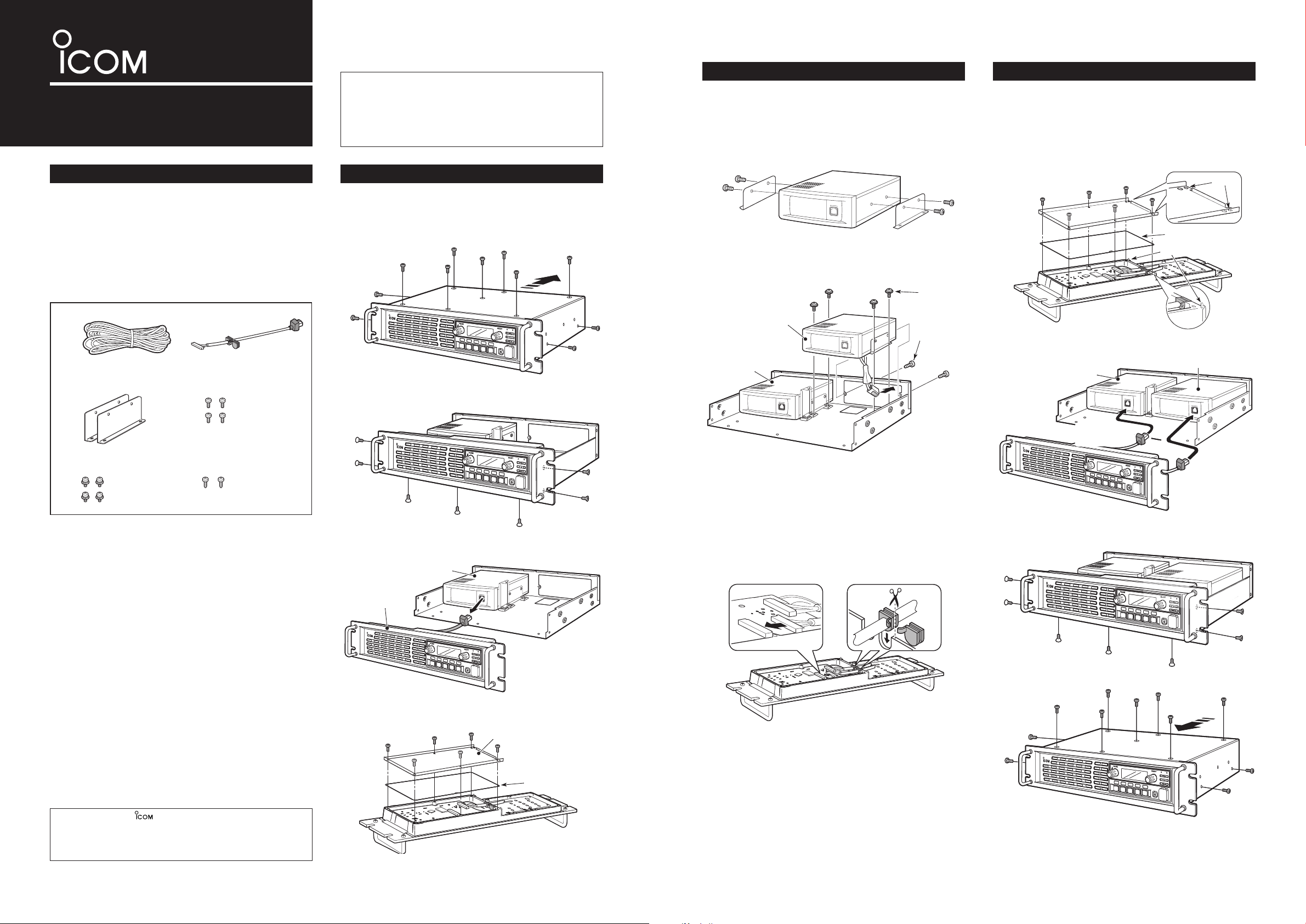
OPENING CASE
INSTALLATION ASSEMBLE THE UNIT
• Install the UR-FR5100 or UR-FR6100
(channel extension module)
q Attach the supplied angles to both sides of the
channel extension module, and tighten the 2 supplied screws (M4×8) on each side.
q Replace the rubber seal and shielding plate of the
front panel, then tighten the 6 screws.
• Make sure the r ubber seal is properly seated in the
groove of the chassis.
• Be sure to match the correct positions of the holes of
the shielding plate and projections of the front panel’s
chassis.
q DC power cable ...................................................1
w Control cable ........................................................1
e Angles ..................................................................2
r Screws (M4×8 mm) ..............................................4
t Set screws (M3×6 mm) ........................................4
y Tapping screws (M3×8 mm) .................................2
q Remove 7 screws from top and 2 screws each
from both sides of the repeater, then slide off the
top cover to the direction of the arrow as illustration
below.
w Remove 3 screws from bottom and 2 screws each
from both sides of the repeater.
e Disconnect the control cable from the channel
module (original), then remove the front panel.
w Install the channel extension module using the sup-
plied screws (Tapping screws: M3×8, Set screws:
M3×6) as shown below.
• Connect the control cable
q Connect the supplied control cable to J502 on the
front board as shown below.
w Cut the rubber caps of the control cables, then in-
sert the rubber caps to the front panel’s chassis as
shown below.
w Connect the control cables to the channel modules.
e Return the front panel, top cover and screws to
their original positions.
Icom, Icom Inc. and the logo are registered trademarks of Icom Incorpor ate d (Japan) in the United Stat es, the United Kingdom, Germany,
France, Spain, Russia and/or other countries.
All other products or brands are registered trademarks or trademarks of
their respective holders.
r Remove 6 screws from the front panel, then re-
move the shielding plate and rubber seal.
Page 2
DECLARATION
OF CONFORMITY
We Icom Inc. Japan
1-1-32, Kamiminami, Hirano-ku
Osaka 547-0003, Japan
Kind of equipment:
VHF REPEATER
Type-designation: iC-fr5100/ur-fr5100
Signature
Authorized representative name
Place and date of issue
Declare on our sole responsibility that this equipment complies with the
essential requirements of the Radio and Telecommunications Terminal
Equipment Directive, 1999/5/EC, and that any applicable Essential Test
Suite measurements have been performed.
Version (where applicable):
This compliance is based on conformity with the following harmonised
standards, specifications or documents:
i)
ii)
iii)
iv)
v)
vi)
vii)
viii)
136–174 MHz 6.25 kHz/12.5 kHz/25 kHz
136–174 MHz 6.25 kHz/12.5 kHz/20 kHz
EN 301 489-1 v1.4.1 (August 2002)
EN 301 489-5 v1.3.1 (August 2002)
EN 300 086-2 v1.1.1 (March 2001)
EN 301 166-2 v1.1.1 (December 2001)
EN 300 219-2 v1.1.1 (March 2001)
EN 300 113-2 v1.3.1 (December 2003)
EN 60950-1: 2001
EN 50385: 2002
0168
Düsseldorf
16th Apr. 2008
Y. Furukawa
General Manager
DECLARATION
OF CONFORMITY
We Icom Inc. Japan
1-1-32, Kamiminami, Hirano-ku
Osaka 547-0003, Japan
Kind of equipment:
UHF REPEATER
Type-designation: iC-fr6100/ur-fr6100
Signature
Authorized representative name
Place and date of issue
Declare on our sole responsibility that this equipment complies with the
essential requirements of the Radio and Telecommunications Terminal
Equipment Directive, 1999/5/EC, and that any applicable Essential Test
Suite measurements have been performed.
Version (where applicable):
This compliance is based on conformity with the following harmonised
standards, specifications or documents:
i)
ii)
iii)
iv)
v)
vi)
vii)
viii)
400–470 MHz 6.25 kHz/12.5 kHz/25 kHz
400–470 MHz 6.25 kHz/12.5 kHz/20 kHz
EN 301 489-1 v1.4.1 (August 2002)
EN 301 489-5 v1.3.1 (August 2002)
EN 300 086-2 v1.1.1 (March 2001)
EN 301 166-2 v1.1.1 (December 2001)
EN 300 219-2 v1.1.1 (March 2001)
EN 300 113-2 v1.3.1 (December 2003)
EN 60950-1: 2001
EN 50385: 2002
0168
Düsseldorf
25th Feb. 2008
Y. Furukawa
General Manager
< Intended Country of Use >
AT
FI
IT
PL
GB
RO
BE
FR
LV
PT
IS
TR
CY
DE
LT
SK
LI
HR
CZ
GR
LU
SI
NO
DK
HU
MT
ES
CH
EE
IE
NL
SE
BG
ABOUT CE
C E Ve r si o ns o f t h e U R - F R 51 0 0 /
UR-FR6100 which display the “CE” symbol
on the serial number seal, comply with the
essential requirements of the European
Radio and Telecommunication Terminal Directive 1999/5/EC.
This warning symbol indicates that this
equipment operates in non-harmonised
frequency bands and/or may be subject to
licensing conditions in the country of use.
Be sure to check that you have the correct
version of this radio or the correct programming of this radio, to comply with national licensing requirement.
• List of Country codes (ISO 3166-1)
Country Codes Country Codes
1 Austria AT
2 Belgium BE
3 Bulgaria BG
4 Croatia HR
5 Czech Republic CZ
6 Cyprus CY
7 Denmark DK
8 Estonia EE
9 Finland FI
10 France FR
11 Germany DE
12 Greece GR
13 Hungary HU
14 Iceland IS
15 Ireland IE
16 Italy IT
17 Latvia LV
18 Liechtenstein LI
19 Lithuania LT
20 Luxembourg LU
21 Malta MT
22 Netherlands NL
23 Norway NO
24 Poland PL
25 Portugal PT
26 Romania RO
27 Slovakia SK
28 Slovenia SI
29 Spain ES
30 Sweden SE
31 Switzerland CH
32 Turkey TR
33 United Kingdom GB
1-1-32 Kamiminami, Hirano-ku, Osaka 547-0003, Japan
A-6657H-1EU-q Printed in Japan
© 2008 Icom Inc.
 Loading...