

Page 1
ICOM
INSTRUCTIONS
DESKTOP
MICROPHONE
SM-26
SM-27
Thank you for purchasing
the
SM-26/
SM-27
desktop
microphone.
These
are
unidirectional, dynamic microphones
designed
for
base
station operation with
an
Icom
transceiver.
Please
thoroughly
read
these
instruc
tions before using
the
microphone.
PRECAUTIONS
CAUTION:
NEVER
expose
the
microphone
to rain,
snoworany
liquids.
CAUTION:
NEVER
let
metal,
wire,
etc.
touch
any
internal part of
the
microphone.
CAUTION:
NEVER
touchoroperate
the
desktop
microphone with
wet
hands.
DO
NOT
place
the
microphoneinexces
sively
dusty
environments
or in direct
sun
light.
DO
NOT
use
harsh
solvents
suchasben
zine
or alcohol to
clean
the
microphone,
as
they
can
damage
the
microphone's
sur
faces.
Place
the
microphone in a
secure
place
to
avoid inadvertent
use
by children.
This
microphone is for
the
specified Icom
transceivers
only! —
The
microphone
can
notbeused
withanon-lcom
transceiver
since
the
powerissuppliedbythe
connect
ed
transceiver.
About
CE
C€
The
SM-26/SM-27
comply
with
the
essential
require
mentsofthe
2004/108/EC
di
rective for
Electromagnetic
Compatibility.
SPECIFICATIONS
Microphone type
Power
requirements
Current
drain
Dimensions
Cable
length
Weight (approximately): SM-26
SM-27
: Unidirectional
dynamic
microphone
(preamp
built-in)
: 8 V DC (supplied by
the
transceiver)
:
Less
than10mA
: 70(W) x 169(H) x 167(D) mm;
23A(W)x62Vfc(H)
* 69/ie(D) in
(Cable is not included)
:30cm±2cm;
1113/i6 in ±2%2 in
390g;13.8
oz
400
g; 14.1
oz
All
stated
specifications
are
subjecttochange
without
noticeorobligation.
Icom, Icom Inc.and the Icom logo are registered trademarks of Icom Incorporated (Japan) in Japan,
the
United
States,
the United Kingdom, Germany,
France,
Spain,
Russia
and/or
other
countries.
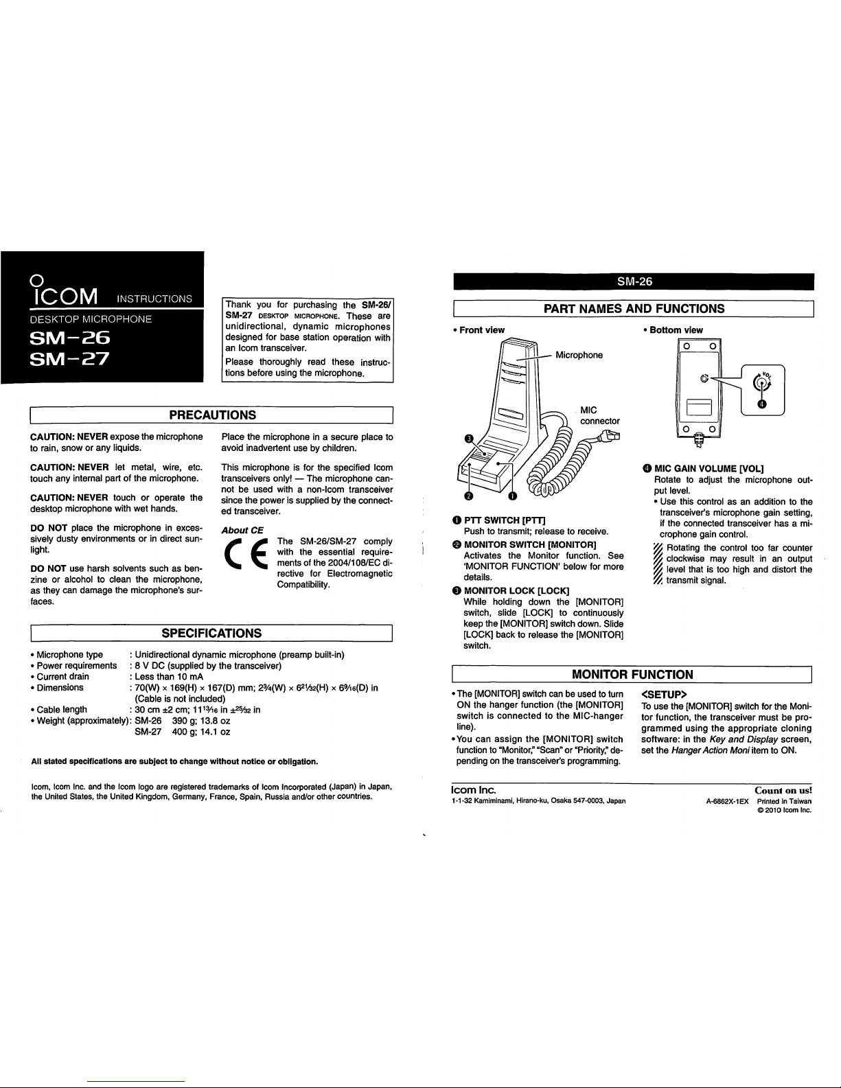
SM-26
PART
NAMES
AND
FUNCTIONS
Front
view
Microphone
O PTT SWITCH [PTT]
Pushtotransmit;
releasetoreceive.
© MONITOR SWITCH [MONITOR]
Activates
the
Monitor
function.
See
'MONITOR
FUNCTION'
below
for
more
details.
© MONITOR LOCK [LOCK]
While holding
down
the
[MONITOR]
switch, slide [LOCK] to continuously
keep
the
[MONITOR] switch down. Slide
[LOCK]
backtorelease
the
[MONITOR]
switch.
•
Bottom
view
O
MIC
GAIN
VOLUME
[VOL]
Rotate to adjust
the
microphone out
put
level.
•
Use
this
controlasan
additiontothe
transceiver's microphone gain setting,
if
the
connected
transceiver
has
a mi
crophone
gain control.
YA
Rotating the control too far counter
w clockwise
may
result inanoutput
yy
level
thatistoo
high
and
distort
the
V/t
transmit signal.
MONITOR
FUNCTION
•
The
[MONITOR]switch
canbeused
to turn
ON
the
hanger
function (the [MONITOR]
switchisconnectedtothe
MIC-hanger
line).
•You
can
assign
the
[MONITOR]
switch
function to
"Monitor,"
"Scan" or
"Priority,"
de
pending on
the
transceiver's programming.
Icom
Inc.
1-1-32 Kamiminami, Hirano-ku,
Osaka
547-0003,
Japan
<SETUP>
To
use
the
[MONITOR] switch for
the
Moni
tor
function,
the
transceiver
mustbepro
grammed
using
the
appropriate
cloning
software:inthe
Key
and
Display
screen,
set
the
Hanger Action Moniitem to ON.
Countonus!
A-6862X-1EXPrintedinTaiwan
©2010
Icom
Inc.
Page 2
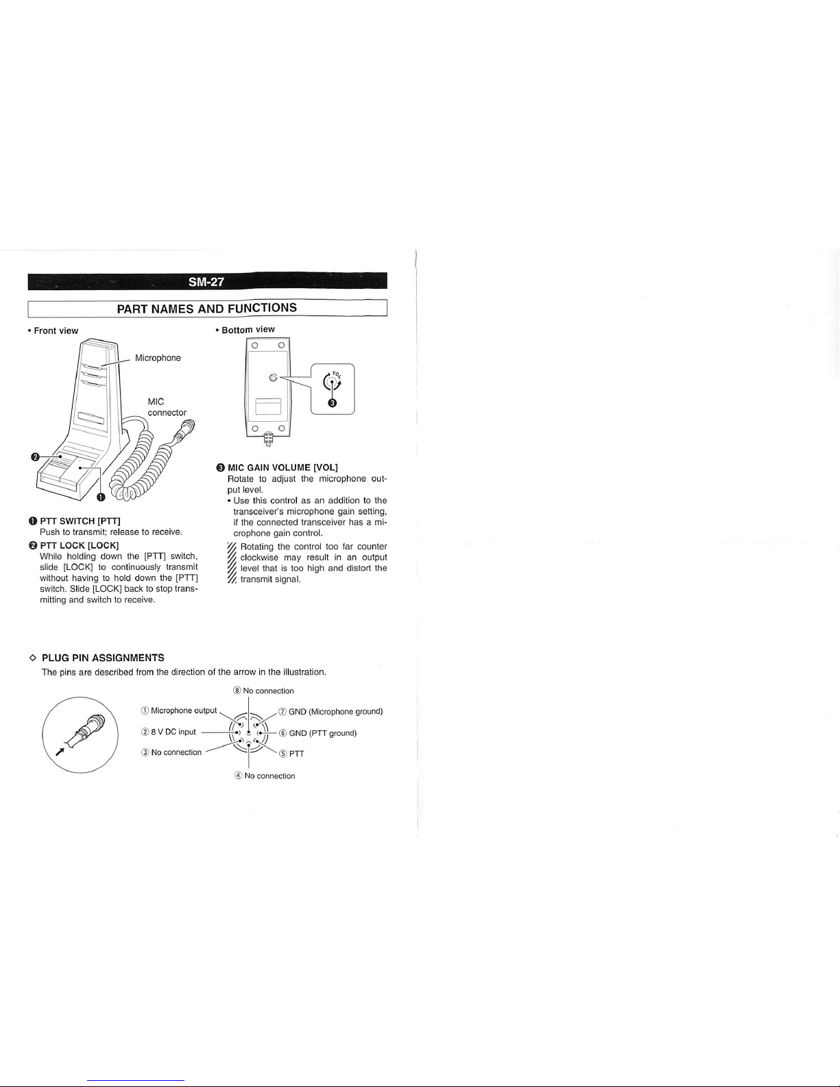
SM-27
PART
NAMES
AND
FUNCTIONS
Front
view
icrophone
O PTT SWITCH [PTT]
Pushtotransmit;
releasetoreceive.
0 PTT
LOCK
[LOCK]
While holding
down
the
[PTT] switch,
slide [LOCK] to continuously
transmit
without having to hold
down
the
[PTT]
switch.
Slide
[LOCK]
backtostop
trans
mitting
and
switchtoreceive.
•
Bottom
view
Q MIC GAIN VOLUME [VOL]
Rotatetoadjust
the
microphone
out
put level.
•
Use
this
controlasan
additiontothe
transceiver's
microphone
gain
setting,
if
the
connected
transceiver
hasami
crophone
gain
control.
VA
Rotating the control too far
counter
y/
clockwise
may
resultinan
output
w level
thatistoo
high
and
distort
the
//.
transmit
signal.
O
PLUG
PIN
ASSIGNMENTS
The
pins
are
described
from the direction of
the
arrow in the illustration.
No
connection
© Microphone output
(2)8 V DC input
3Noconnection
©
GND
(Microphone ground)
-4-!—GGND
(PTTground)
5
PTT
5 No connection
 Loading...