

Page 1

INSTRUCTION MANUAL
ACCESS POINT
MANAGEMENT TOOL
RS-AP3
INTRODUCTION
1 USING THE RS-AP3
2 OPERATING SCREEN
3 MENU
4 INDIVIDUAL CONFIGURATIONS
5 COMMON CONFIGURATION
6 INFORMATION
INDEX
These instructions contain important safety and operating instructions for the RS-AP3.
Page 2

INTRODUCTION
Thank you for choosing this Icom product. The RS-AP3 access point management tool is designed and built with
Icom’s IP network technology. We hope you agree with Icom’s philosophy of “technology first.” Many hours of
research and development went into the design of your RS-AP3.
NOTE:
To start the wireless access point management, you must “Enable” the “Access Point Management Tools.”
(+p.1-4)
Set the static IP address to your PC.
If you use the RS-AP3 for the first time, read through operation instructions written in the chapter 1.
System requirements
D PC
CPU Clock speed: Dual Core 2 GHz or more (32 bit (x86) or 64 bit (x64) processor)
System memory: 2 GB or more
Hard disk: At least 2 GB of free space.
D Operating system
Microsoft® Windows Server® 2012 R2
Microsoft® Windows Server® 2012
Microsoft® Windows Server® 2008 R2 (SP1 or later)
Microsoft® Windows Server® 2008 (SP2 or later)
Microsoft® Windows® 8.1 (Except for Windows RT 8.1)
Microsoft® Windows® 10
Microsoft® Windows® 7 (SP1 or later)
• The RS-AP3 cannot be used with Microsoft® Windows® RT 8.1.
• The RS-AP3 can be used with both 32 and 64 bit versions of the operating systems listed above.
• These Instructions are based on using Windows 7.
• These screen captures in the instructions may slightly differ, depending on the operating system used.
Icom, Icom Inc. and the Icom logo are registered trademarks of Icom Incorporated (Japan) in Japan, the United States, the
United Kingdom, Germany, France, Spain, Russia, Australia, New Zealand, and/or other countries.
Microsoft, Windows and Windows Server are registered trademarks of Microsoft Corporation in the United States and/or
other countries.
All other products or brands are registered trademarks or trademarks of their respective holders.
i
Page 3

INTRODUCTION
Product information
• Wireless access points of the same model can be managed by one group.
A total of 64 groups can be programmed.
The license of the RS-AP3 is as follows.
Number of access points managed
➥ 3000 access points (maximum)/64 groups (total)
➥ 128 access points (maximum)/1 group
Number of groups
➥ 64 groups (total)
• Start the RS-AP3 to manage the access points in the groups.
Until the management is completed, changes cannot be made on an access point’s setting screen.
• Multiple access points can be managed individually or collectively.
• From the access points scanning results, power level and channels according to the system environment can
automatically be set to the access points.
• Load balance can be managed based on information received periodically from the access points, according
to the wireless LAN devices.
• Radio wave environment status can be displayed on a graph according into the data received from the access
points.
• Management is automatically enabled when an access point to be managed is detected.
• The Site Survey function and MAC Authentication (RADIUS) server are inside the RS-AP3.
• The SSID or encryption settings for access points programmed to all groups can be displayed on a list.
• If an access point with a previous firmware version is detected, it can automatically be updated.
• Access point information can periodically be sent, or messages can be sent when an unauthorized access or
a notification fault is detected.
➥ You can set it not to send messages when none of an unauthorized access or a notification fault is detected.
• Synchronizing the setting data with another PC with the RS-AP3 installed can avoid unmanageability caused
by communication fault.
➥ When using the mirroring function, 2 different RS-AP3 (USB flash drives) on the same license are necessary.
• The RS-AP3 consists of the Windows® service (shown below) that resides for managing the operating screen
and wireless access points.
Operating screen Service
For editing settings and
displaying logs.
As the Operating screen and Windows service
are different programs, information is exchanged
by using setting files.
• After editing the setting contents on the
Operating screen, the setting file needs to be
saved and applied to the Windows service
side.
ii
Managing wireless access
points, according to the
setting file contents.
• Operation starts when
Windows
®
starts
Page 4

INTRODUCTION
Installation note
• When the RS-AP3 USB flash drive is inserted into the USB port, “REMOVABLE drive” and “Setup.exe” appear.
The flash drive must be inserted into the PC when saving the setting files or synchronizing with the mirroring
function.
• The RS-AP3 resides as a Windows service. Therefore, you can manage the access points, using saved setting files.
After setting the access points to manage on the operation screen, remove the flash drive.
➥ Modifications are applied to the service when the contents modified with the software are overwritten.
➥ If you load a setting file that is saved in advance, save it again with the RS-AP3.
• To synchronize the setting data between the RS-AP3 and an access point, overwrite the settings entered on
the operation screen, and then send them to the access point.
• When the access point management is completed (+p.1-21), “Access Point Management Tools” automatically return to “Disable.”
To manage the access point again, you must “Enable” the “Access Point Management Tools.”
(+p.1-4)
• When using the Wireless Bridging communication function, you must activate the function in order for the access points to communicate, before enabling the “Access Point Management Tools.”
iii
Page 5

INTRODUCTION
Table of contents
INTRODUCTION …………………………………… i
System requirements …………………………… i
Product information ……………………………… ii
Installation note …………………………………iii
Table of contents ……………………………… iv
1. USING THE RS-AP3 ………………………… 1-1
1. Before using the RS-AP3 ………………… 1-2
2. Setting the wireless access point ………… 1-3
3. Starting the RS-AP3 ……………………… 1-5
2. OPERATING SCREEN ……………………… 2-1
1. Screen description ………………………… 2-2
2. Tool bar ……………………………………… 2-3
3. Group tab and SYSLOG tab ……………… 2-4
4. Map tab, Individual tab and Common tab. 2-5
5. Map screen ………………………………… 2-6
6. Output Log screen ………………………… 2-8
7. Property screen …………………………… 2-9
8. SYSLOG screen ………………………… 2-12
5. COMMON CONFIGURATION ……………… 5-1
1. Operating …………………………………… 5-2
2. Model ………………………………………… 5-3
3. Network Settings …………………………… 5-4
4. Wireless Settings …………………………… 5-6
5. Management …………………………… 5-10
6. Command ………………………………… 5-11
7. Load Balancing ………………………… 5-12
6. INFORMATION ……………………………… 6-1
1. Notification by email function ……………… 6-2
2. To prevent the management inability …… 6-7
3. Background bitmap setting …………… 6-14
4. Firewall setting …………………………… 6-15
3. MENU ………………………………………… 3-1
1. File menu …………………………………… 3-2
2. Group menu ………………………………… 3-3
3. Access Point menu ………………………… 3-6
4. Option menu ……………………………… 3-24
5. View menu ……………………………… 3-34
6. Help menu ……………………………… 3-35
4. INDIVIDUAL CONFIGURATIONS ………… 4-1
1. Operating …………………………………… 4-2
2. IP Address ………………………………… 4-3
3. DHCP Server ……………………………… 4-4
4. Packet Filter ………………………………… 4-5
5. Wireless Settings …………………………… 4-7
6. SNMP ……………………………………… 4-8
7. Command …………………………………… 4-9
iv
Page 6

USING THE RS-AP3
1. Before using the RS-AP3 ………………………………………………………………………………………… 1-2
2. Setting the wireless access point ………………………………………………………………………………… 1-3
1. Setting the wireless access point IP address ……………………………………………………………… 1-3
Setting the wireless access point to the RS-AP3 mode ……………………………………………………… 1-4
2.
3. Starting the RS-AP3 ……………………………………………………………………………………………… 1-5
1. Starting the RS-AP3 …………………………………………………………………………………………… 1-5
2. Adding wireless access point groups ………………………………………………………………………… 1-7
3. Adding wireless access points ………………………………………………………………………………… 1-8
4. Setting wireless access point IP address ………………………………………………………………… 1-10
5. Saving the access point setting data ……………………………………………………………………… 1-11
Modifying the settings ……………………………………………………………………………………… 1-12
6. Starting the management …………………………………………………………………………………… 1-13
7. Importing wireless access point settings ………………………………………………………………… 1-14
8. Changing the wireless access point settings ……………………………………………………………… 1-16
9. Overwriting the setting data ………………………………………………………………………………… 1-18
10. Sending the modified settings ……………………………………………………………………………… 1-19
11. Ending the management …………………………………………………………………………………… 1-21
12. Closing the RS-AP3 ………………………………………………………………………………………… 1-23
2
1-1
Page 7

USING THE RS-AP3
2
1. Before using the RS-AP3
Before using the RS-AP3 for the first time, follow these instructions.
1.
SETTING THE
WIRELESS
ACCESS POINT
2.
STARTING THE RS-AP3
1. Setting the wireless access point IP address (+p.1-3)
Set the IP address and network settings on the “IP Address” screen to
manage with the RS-AP3.
2. Setting the wireless access point to RS-AP3 mode (+p.1-4)
Before using the RS-AP3, you must “Enable” the “Access Point Man-
agement Tools” on the setting screen.
1. Starting the RS-AP3 (+p.1-5)
2. Adding groups (+p.1-7)
3. Adding wireless access points (+p.1-8)
4. Setting wireless access point IP address (+p.1-10)
Set the IP address set for the access point.
5. Saving the setting data (+p.1-11)
Save the access point setting data as a setting file (extension: rsap3)
on the PC.
• After editing the contents, you must save the setting file and apply it
to the Windows service.
6. Starting the management (+p.1-13)
7. Importing wireless access point settings (+p.1-14)
To reuse the contents set to the access points, load the setting data
from access point.
8. Changing the wireless access point settings (+p.1-16)
If needed, click [Individual Configurations] and [Common Configura-
tion] to change the access point setting contents.
9. Overwriting the setting data (+p.1-18)
• After editing the contents, you must save the setting file and apply it
to the Windows service.
10. Sending the modified settings (+p.1-19)
11. Ending the management (+p.1-21)
To continue the management on the Windows service, skip to the steps
on page 1-23.
12. Closing the RS-AP3 (+p.1-23)
1-2
Page 8
USING THE RS-AP3
2
2. Setting the wireless access point
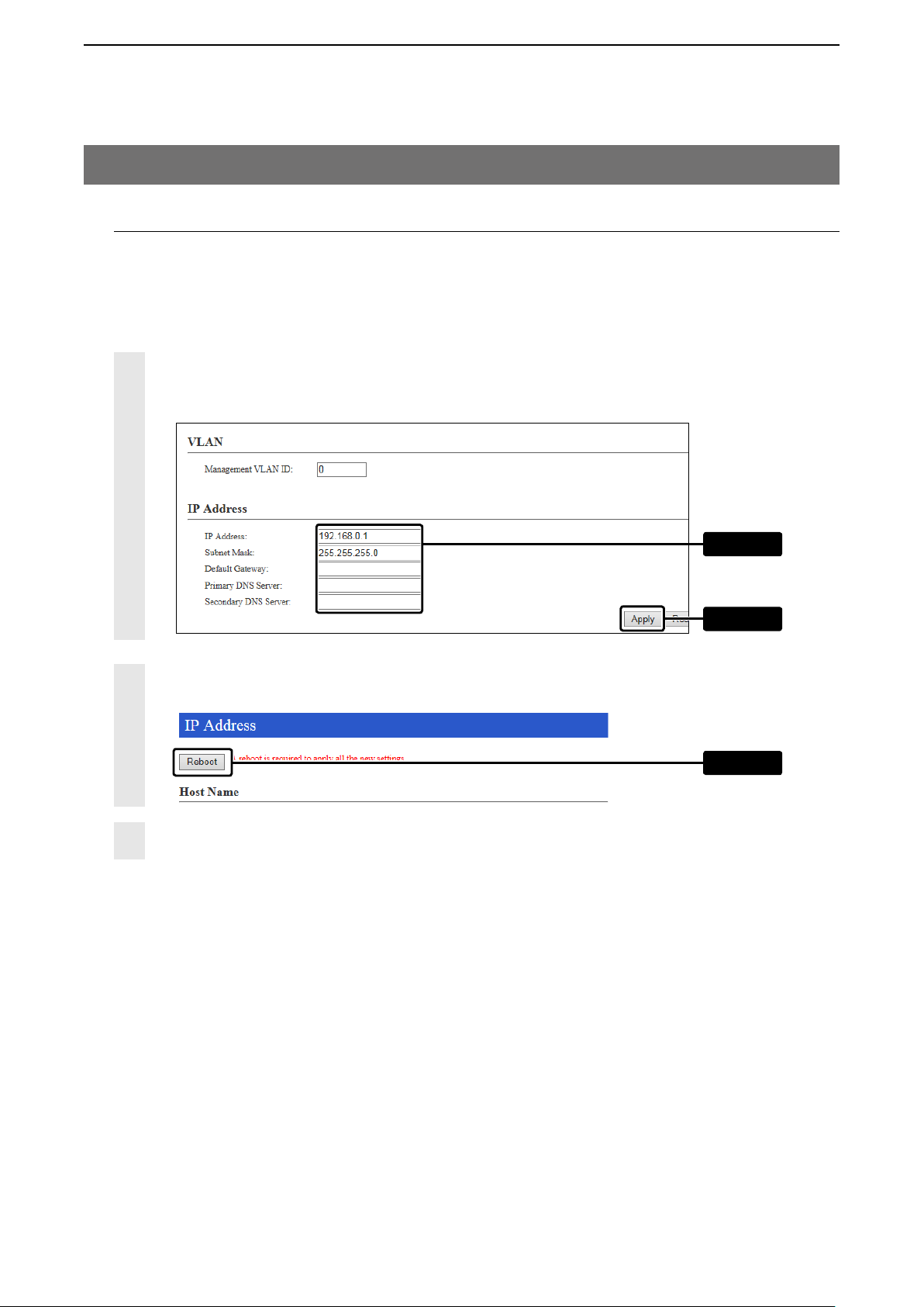
1. Setting the wireless access point IP address
Set the IP address and network settings for the access point on the “IP Address” screen.
• Make sure the IP address is not the same as the other network’s address.
• Refer to the access point’s instruction manual for details on accessing the setting screen.
• The instruction manual is described based on the AP-90M.
1
Edit the [IP Address] settings on the “IP Address” screen, and then click [Apply].
• If you want to change the IP address’s “network part (Example: 192.168.0),” also change the IP address on
the PC.
Click [Reboot].
2
• Follow the instructions to restart the AP-90M.
After restarting, click [Back].
3
The “Login to AP-90M” window is displayed to enter the user ID and password.
q Edit
w Click
Click
1-3
Page 9
USING THE RS-AP3
2
2. Setting the wireless access point (Continued)
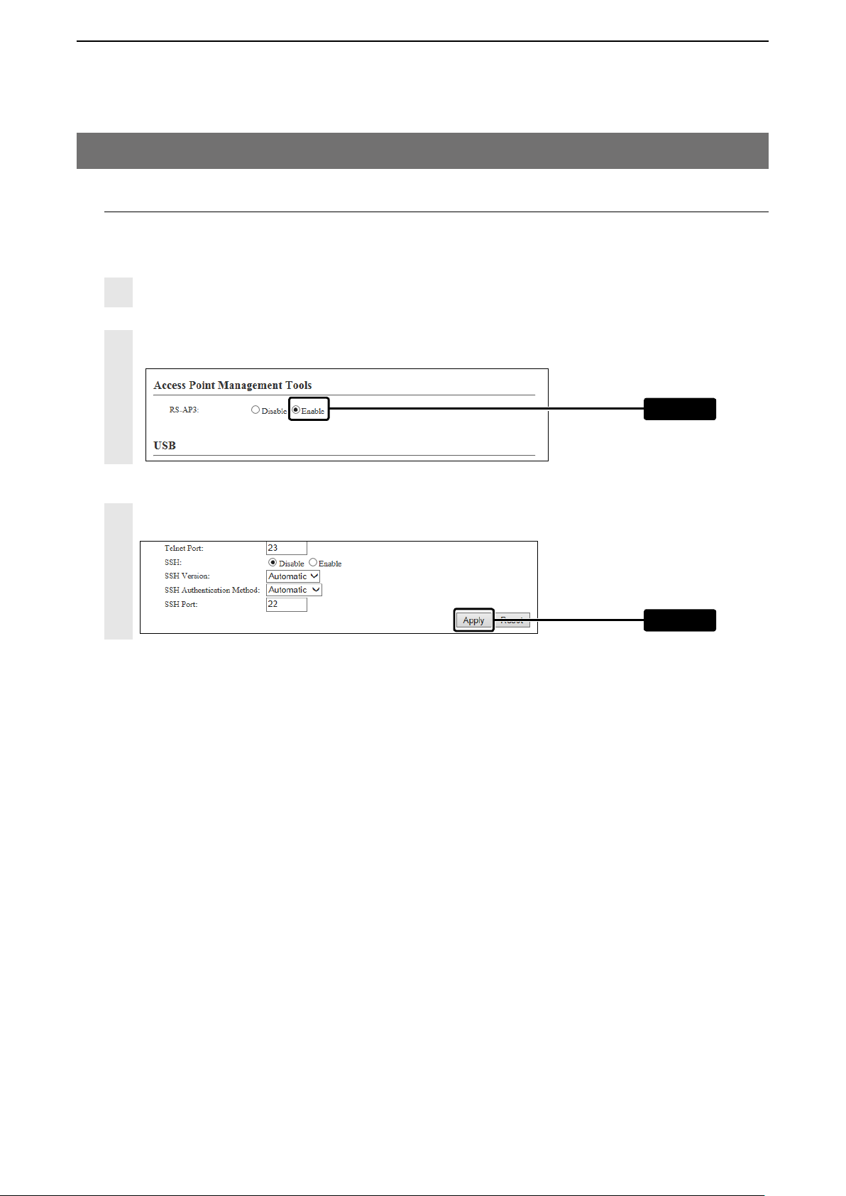
2.
Setting the wireless access point to the RS-AP3 mode
Before using the RS-AP3, you must set the “Access Point Management Tools” to “Enable.”
Click “Management” and then “Management Tools.”
1
The “Management Tools” screen is displayed.
“Enable” the [Access Point Management Tools].
2
Select
3
Click [Apply].
Click
1-4
Page 10
USING THE RS-AP3
2
3. Starting the RS-AP3
NOTE:
• After the installation has completed, the RS-AP3 USB flash drive must also be inserted into the PC
when you first run the RS-AP3 software.
• After running the software for the first time, the flash drive does not have to be inserted.
When a USB flash drive needs to be inserted, such as in the following operation, insert the same flash
drive that you used when you first ran the software.
➥ Saving or opening a setting file.
➥ Synchronizing using the mirroring function. (
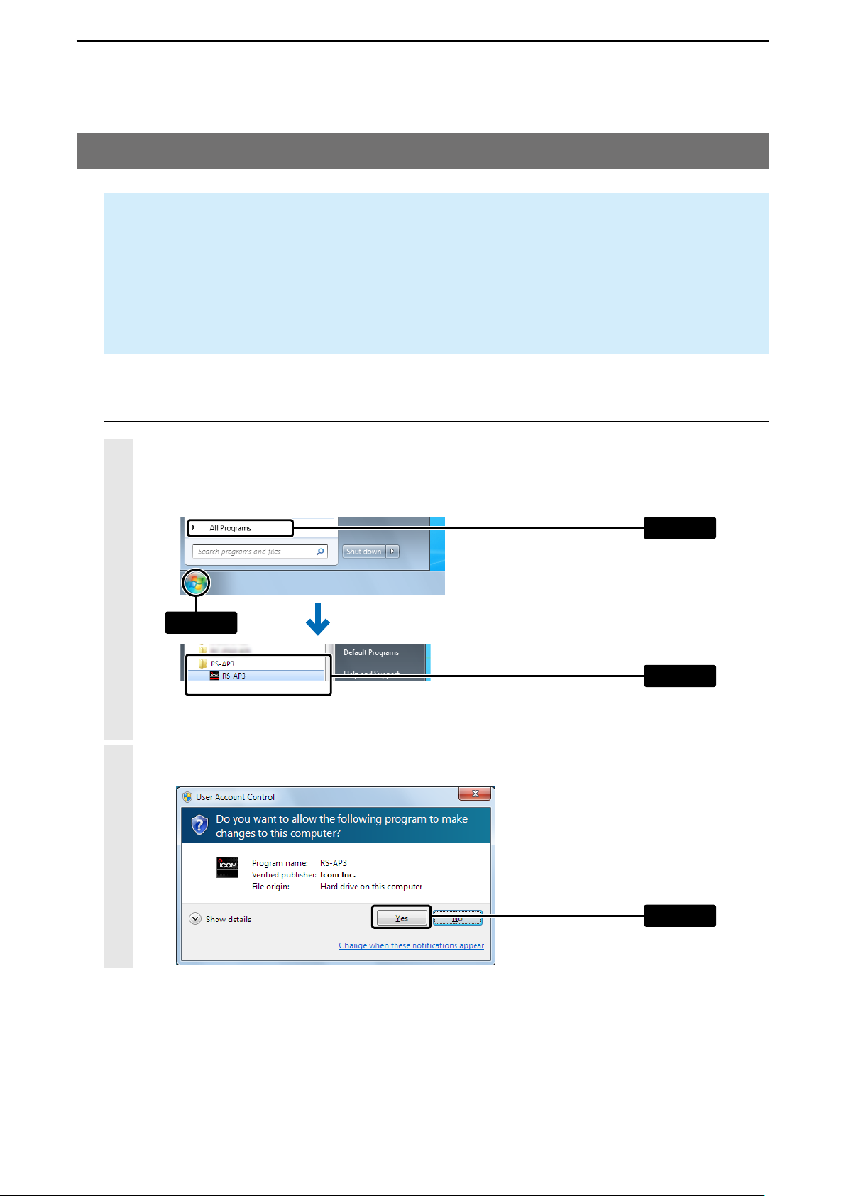
1. Starting the RS-AP3
1
Click the RS-AP3 icon in the Start menu.
You can also start the software by simply double-clicking the RS-AP3 icon on your desktop.
• These Instructions are based on using Microsoft® Windows® 7.
+p.6-10)
q Click
2
If the “User Account Control” window appears, click [Yes] to continue.
w Click
e Click
Click
1-5
Page 11
USING THE RS-AP3
2
3. Starting the RS-AP3
1. Starting the RS-AP3 (Continued)
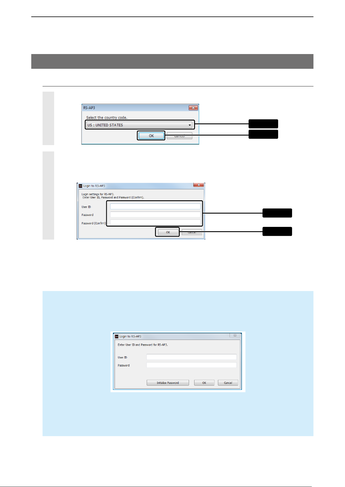
Select the country code from the drop-down list.
3
Enter a desired User ID, Password and Password (Confirm) of up to 31 characters and symbols, and then
4
click [OK].
• Use numbers, characters and letters (both lower and upper case).
q Click
w Click
q Click
w Click
NOTE:
The next time you start the RS-AP3, you will need to enter the User ID and the password that you entered.
• Without the User ID and Password, you cannot start the RS-AP3.
If you click [Initialize Password], the User ID and Password are cleared, and will have to be reentered.
• To open the setting file saved with a different User ID or Password (+p.1-11), the User ID and Pasword entry
window appears. (+p.2-3, p.3-2)
To open the setting files saved with a different User ID and Password, enter the ones that you entered when you
saved them.
1-6
Page 12
USING THE RS-AP3
2
3. Starting the RS-AP3 (Continued)
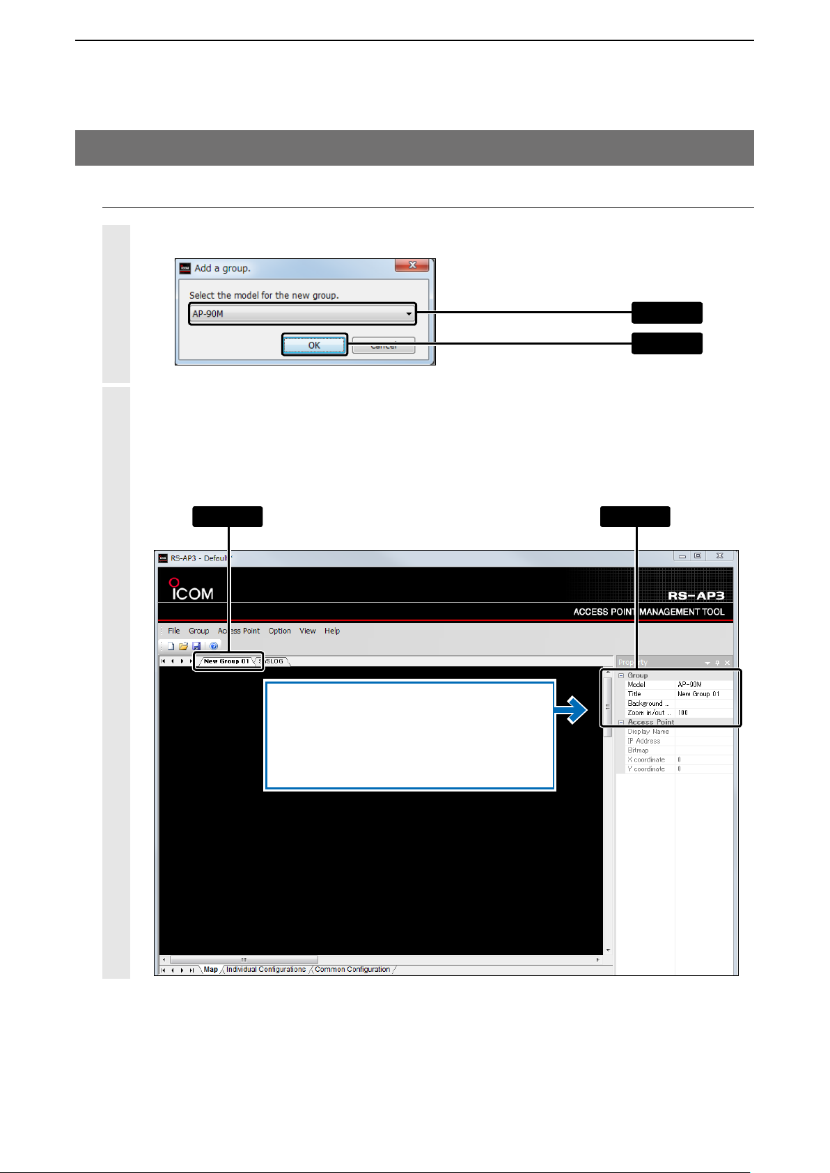
2. Adding wireless access point groups
1
Select the access point device to assign to the new group to, and then click [OK].
Select the assigned group.
2
Enter a “Title” (up to 32 characters), ”Background Bitmap,” for example.
• Only the same access points can be managed in a group.
• To set the common configurations to a different access point, you need to separate into different groups to
manage.
q Click
w Click
q Click w Set
When setting the Background Bitmap
First, save the picture file (24 bitmap format) in
the RS-AP3 installated folder. (Icom > RS-AP3 >
BG) (+p.6-14)
1-7
Page 13
USING THE RS-AP3
2
3. Starting the RS-AP3 (Continued)
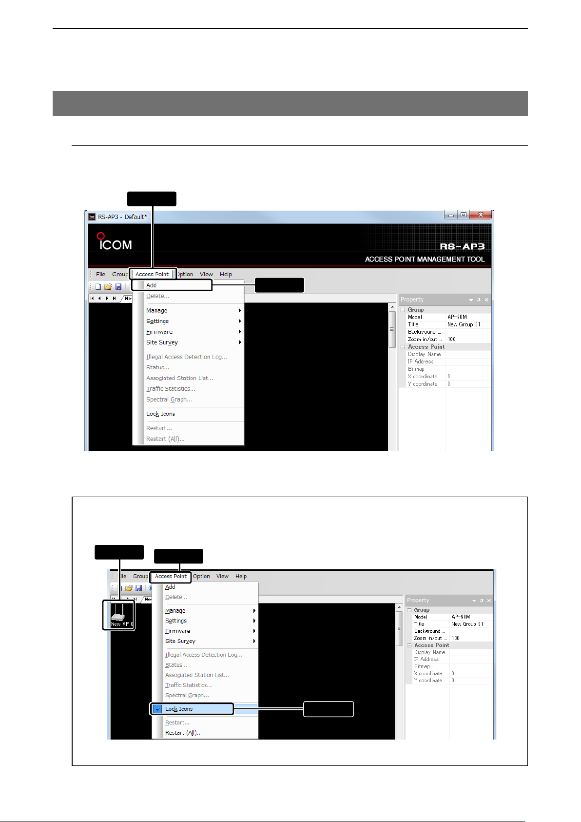
3. Adding wireless access points
Click “Access Point,” then “Add” to add an access point to a group.
• You can also add an access point from the menu that is displayed by right-clicking on the map screen.
q Click
w Click
Locking the wireless access point icons
To lock the access point icons, select the access point on the map screen and click “Access point,” and
then click “Lock Icons.”
q Click
• Even while it is locked, the coordination (positioning) can be changed in Property on the map screen. (+p.1-10)
w Click
e Click
1-8
Page 14
USING THE RS-AP3
2
3. Starting the RS-AP3
3. Adding wireless access points (Continued)
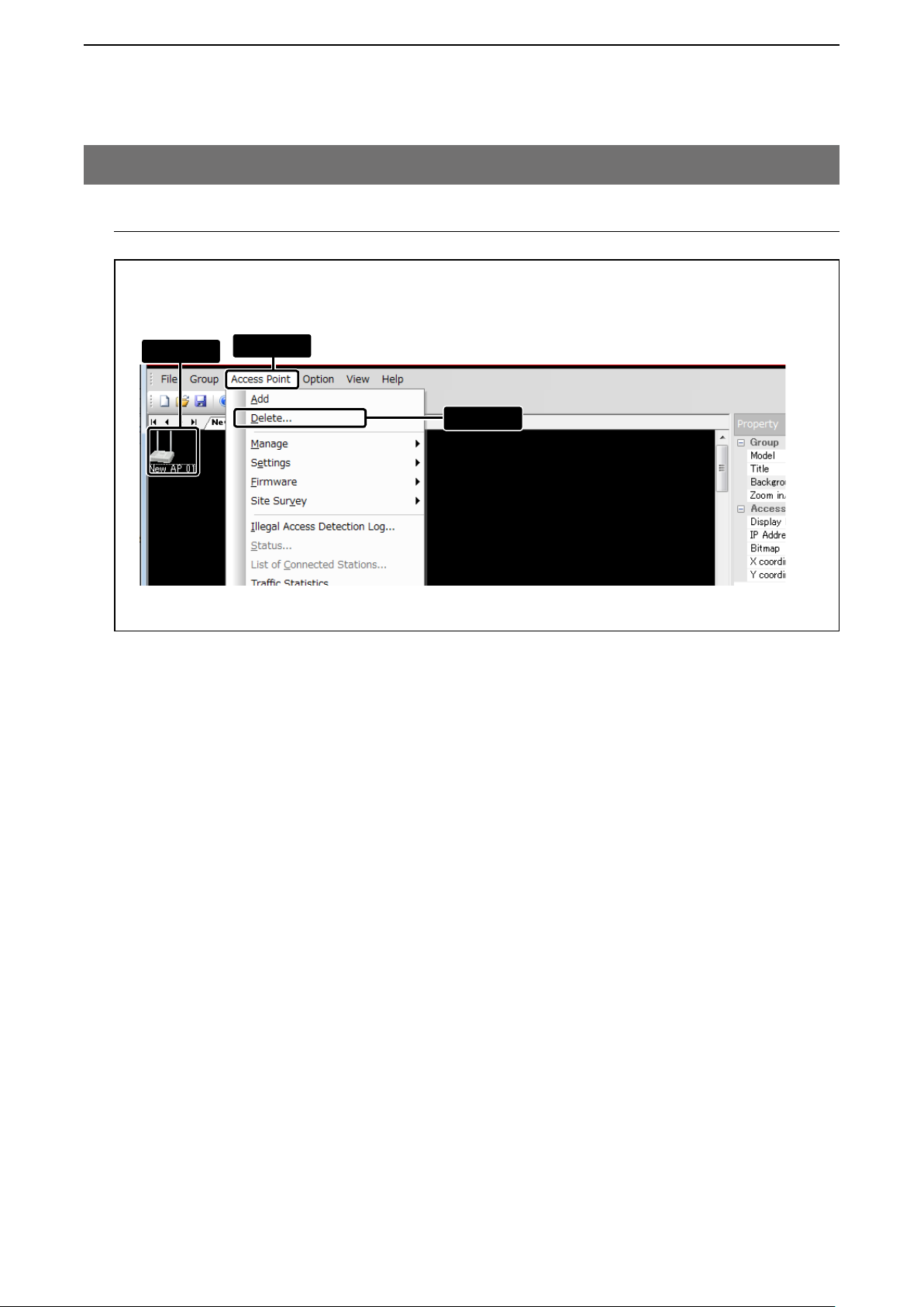
Deleting a wireless access point
To delete an access point, select the access point on the map screen and click “Access point,” and then
click Lock icons.
q Click
• The icon can also be deleted from the menu that is displayed by right-clicking on the map screen.
w Click
e Click
1-9
Page 15
USING THE RS-AP3
2
3. Starting the RS-AP3 (Continued)
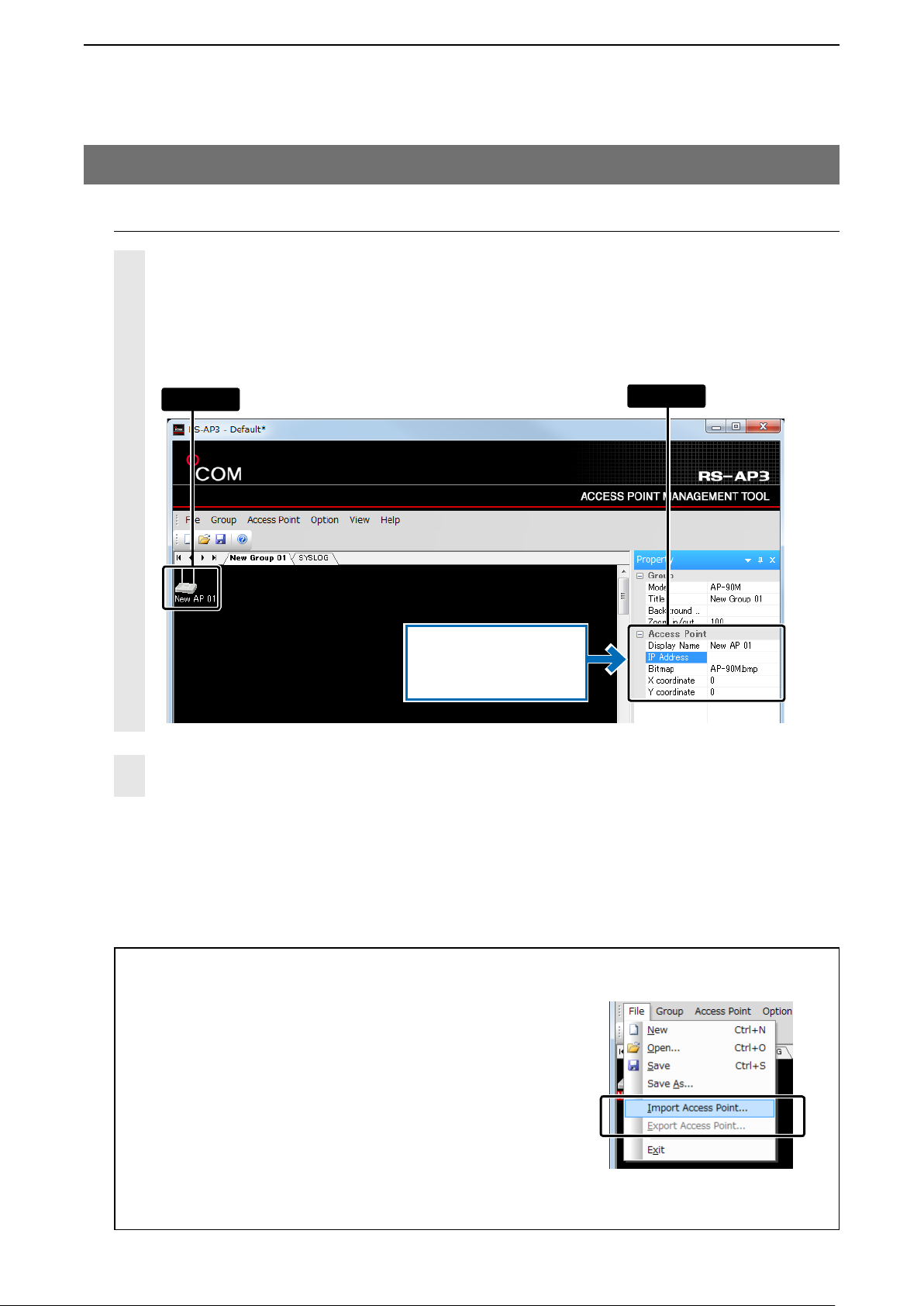
4. Setting wireless access point IP address
1
Select the added access point, and then enter the IP address.
Enter the “Display Name” (of up to 32 characters) and select the icon from the “Bitmap” list.
• To manage the access points with the RS-AP3, you need to enter an IP address.
• Selecting an access point icon on the map screen will display the access point’s name and information in the
“Property” display.
q Click
If necessary, enter
“Display Name,” “Bitmap,”
and “X/Y Coordinate.”
Repeat “Adding wireless access points” (+p.1-8) and the above settings to add access points to in
2
the group.
w Set
Importing/Exporting access point information
The registered access point’s information* can be exported in the
CSV format, or the exported file can be imported into the RSAP3.
• If the access point’s IP address is the same as other group’s IP address, the information cannot be imported or exported.
• If the information is the same as the registered access point, the information is overwritten.
• An exported file can be edited with a text editor.
• Importing other files than the exported files is not guaranteed.
* Access point information includes group and model title, IP address,
display name and coordinates (positioning) on the map screen.
1-10
Page 16
USING THE RS-AP3
2
3. Starting the RS-AP3 (Continued)
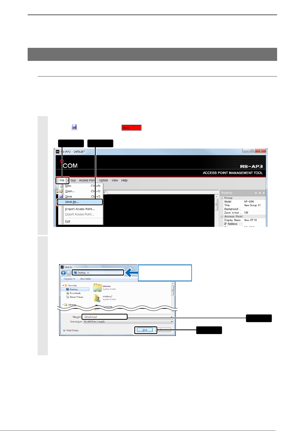
5. Saving the access point setting data
Save the access point setting data as a setting file (extension: rsap3) on the PC.
• The last saved setting file automatically loads the next time you start the software.
We recommend that you do not move the setting file from where you saved it.
1
Click “File” and then “Save As...”
Clicking
, or double-clicking on the status bar, will also save the setting data.
q Click w Click
2
When the “Save As...” window is displayed, set the desired file name, and then click [Save].
• The setting file (extension: rsap3) is saved in the selected location.
If necessary, change the
location.
w Click
q Set
1-11
Page 17
USING THE RS-AP3
2
3. Starting the RS-AP3
5. Saving the access point setting data (Continued)
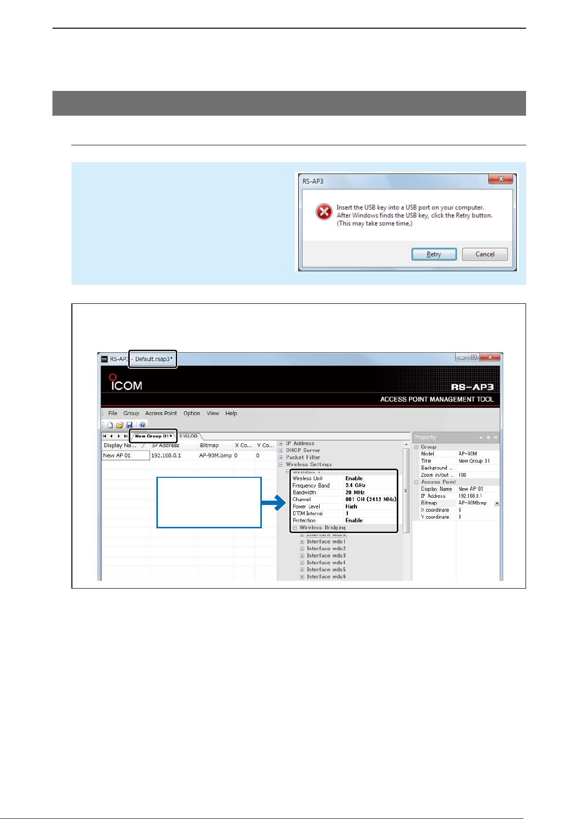
NOTE
When saving a setting file, you must insert the
USB flash drive that was used when the RSAP3 started.
If the dialog to the right is displayed, insert the
flash drive, and then click [Retry].
Modifying the settings
If the setting data is modified after the file has been saved, “*” appears on the title bar and the group
title.
The settings modified in
the individual or common
configurations are displayed in bold letters.
1-12
Page 18
USING THE RS-AP3
2
3. Starting the RS-AP3 (Continued)
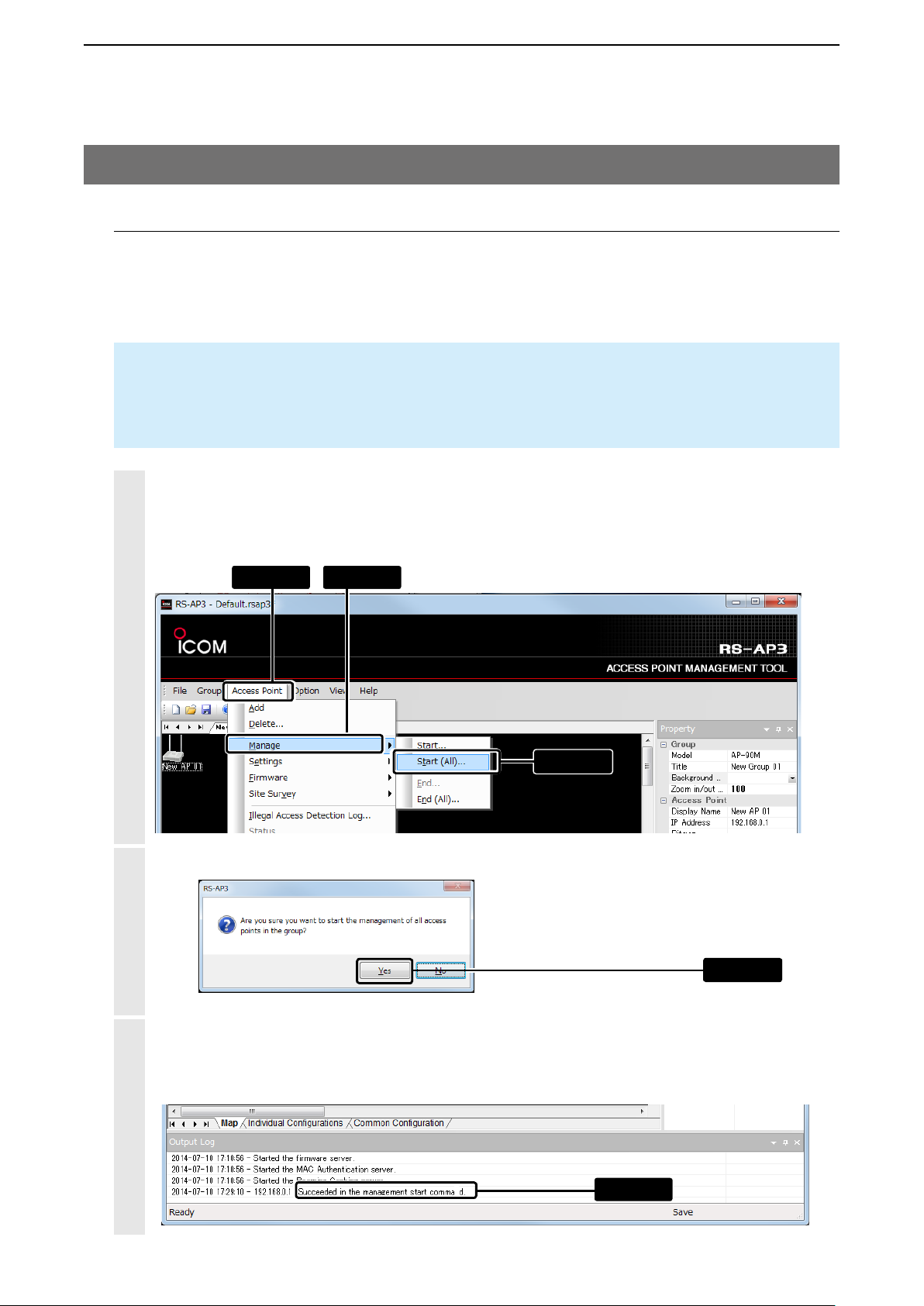
6. Starting the management
When the management is started, the access point’s setting data can be imported (+p.1-14) or exported
(+p.1-19) from the RS-AP3.
• The settings on the access point setting screen cannot be modified until the management is finished.
• Refer to page 2-7 for the access point status display (color) details.
NOTE
To start the management, you must “Enable” the “Access Point Management Tools.”
When you finish the access point management (+p.1-21), the management tool settings on the access
point automatically returns to “Disable.”
1
Click “Access Point” > “Manage” > “Start (All)...”
• You can select it from the menu that displays by right-clicking on the map screen.
• To start managing the access points one by one, select the access point on the map screen, and then click
[Start].
2
q Click w Click
e Click
Click [Yes].
Click
3
When you start the access point management, “Succeeded in the management start command” is
displayed.
• If “Failed in the management start command” is displayed, check the access point connection of the IP address.
Check
1-13
Page 19
USING THE RS-AP3
2
3. Starting the RS-AP3 (Continued)
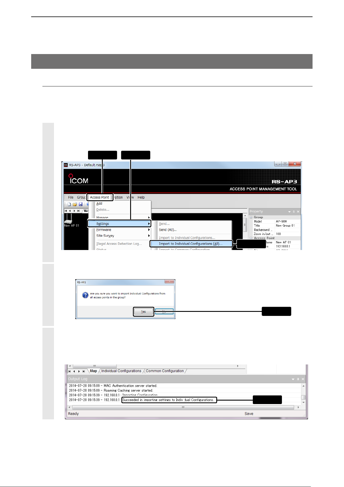
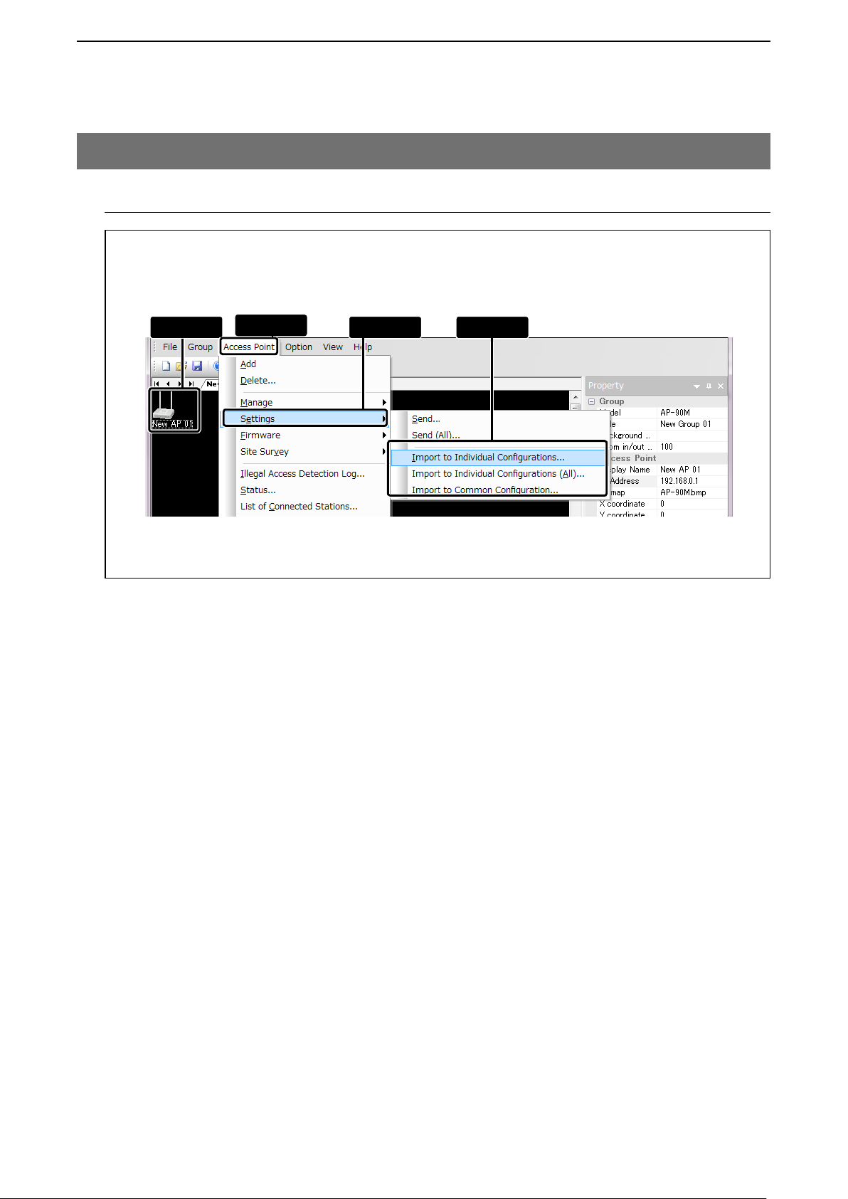
7. Importing wireless access point settings
To use the contents set to the access points, import the configuration data from the access points.
• To set the “Common Configuration” contents (+p.5-1) as the access point setting, select the access point on the map
screen, and then load the setting data. (+p.1-15)
1
Click “Access Point” > “Settings” > “Import to Individual Configurations (All)...”
• You can select it from the menu that is displayed by right-clicking on the map screen.
q Click w Select
e Click
2
Click [Yes].
Click
3
When the setting data is imported, “Succeeded in importing settings to Individual Configurations”
displays.
• If “Cannot import to Individual Configurations” is displayed, check the access point connection of the IP address.
Check
1-14
Page 20
USING THE RS-AP3
2
3. Starting the RS-AP3
7. Importing wireless access point settings (Continued)
Importing setting data individually from wireless access points
Select the access point on the map screen, and then click “Access Point” > “Settings” > “Import to Individual Configurations...” or “Import to Common Configuration...”
w Click
• You can select it from the menu that is displayed by right-clicking on the map screen.
e Select r Clickq Click
1-15
Page 21
USING THE RS-AP3
2
3. Starting the RS-AP3 (Continued)
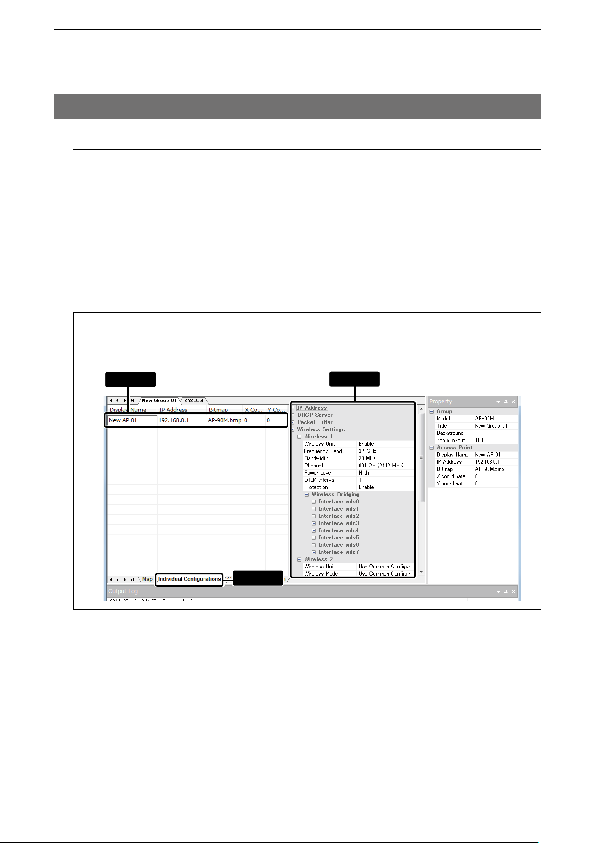
8. Changing the wireless access point settings
If necessary, click [Individual Configurations] or [Common Configuration] to change the access point setting
contents.
Individual Configurations: Individually sets access points
Common Configuration: Sets all access points in the group
• The Individual Configuration contents take prior over the Common Configuration contents.
• To set the common configurations to a different product, you need to separate into different groups to manage.
• Only the same products can be managed in a group.
• Refer to the access point’s instruction manual or the setting screen online help.
Setting on the Individual Configurations screen
Select the setting access point from the access point list in the selected group, and then click the setting
item.
q Click
e Setw Click
1-16
Page 22
USING THE RS-AP3
2
3. Starting the RS-AP3
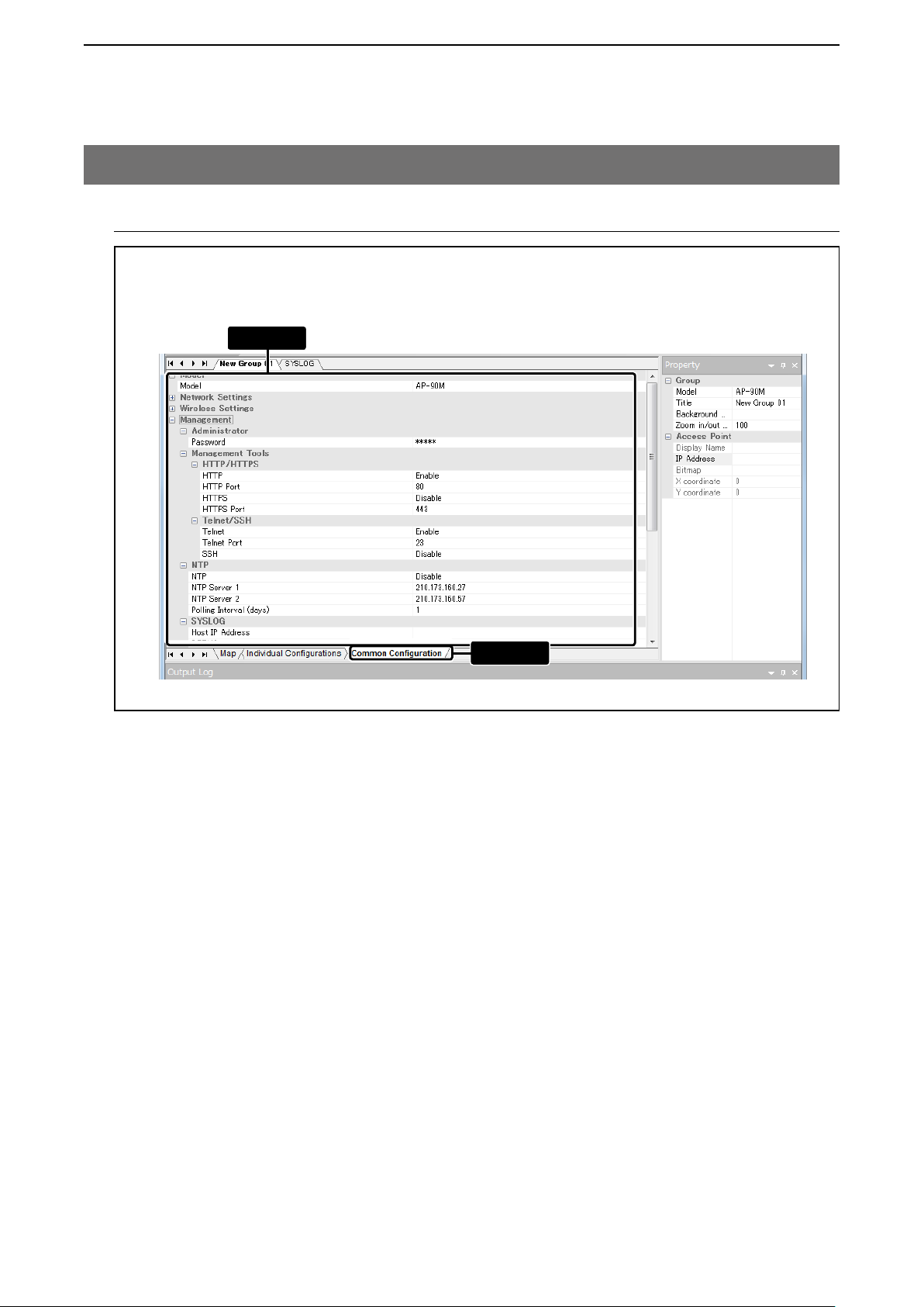
8. Changing the wireless access point settings (Continued)
Setting on the Common Configuration screen
Among the access points set to the selected group, click the items to set in the group.
w Set
q Click
1-17
Page 23
USING THE RS-AP3
2
3. Starting the RS-AP3 (Continued)
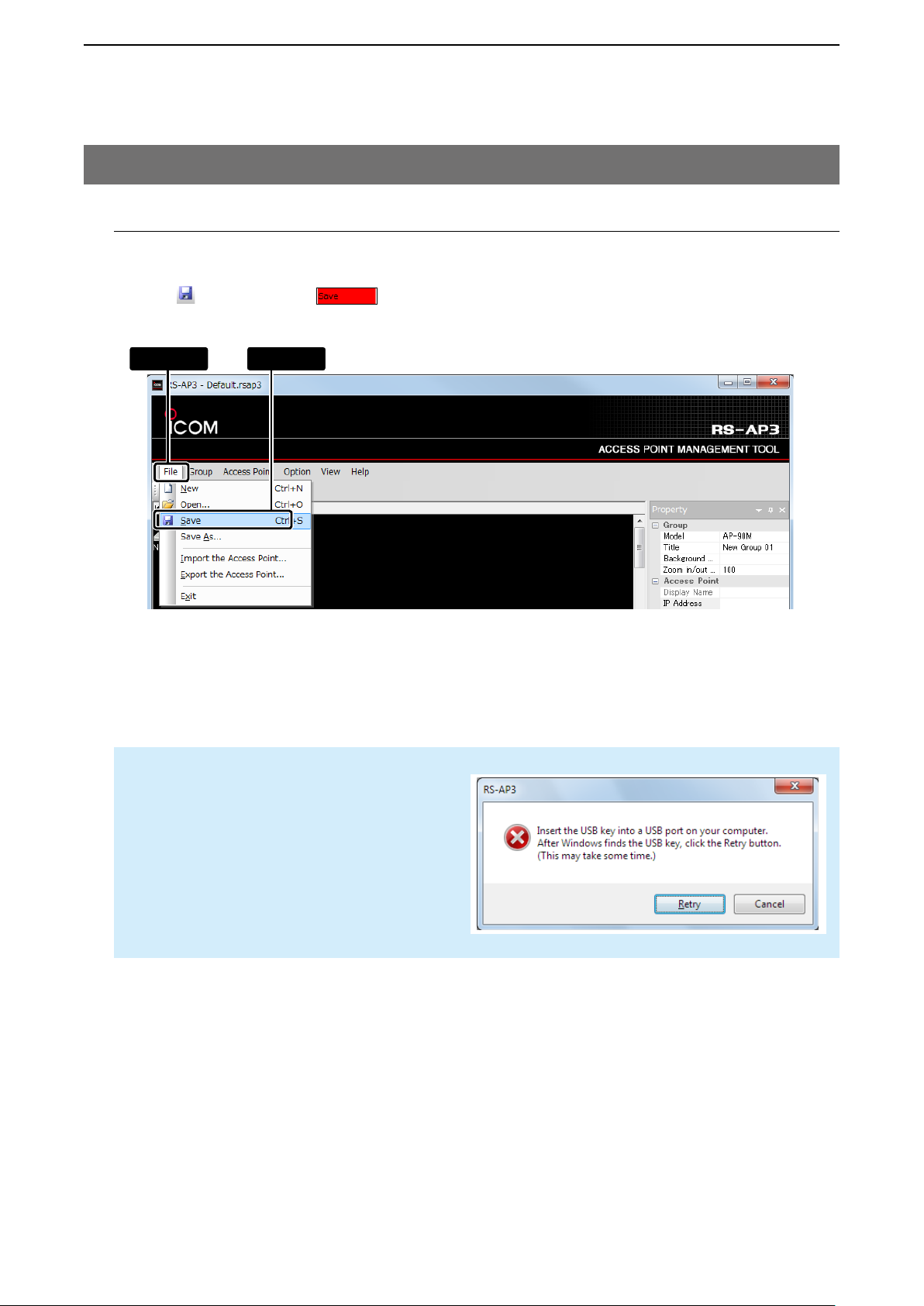
9. Overwriting the setting data
To apply the modified access point setting contents to the Windows service, click “File” and then “Save” to
overwrite the setting file. (extension: rsap3)
• Clicking or double-clicking will also save the file.
• To manage the access points using the saved setting files, save the changes constantly to apply it to the service.
q Click w Click
NOTE
When saving a setting file, you must insert the
USB flash drive that was used when the RSAP3 started.
If the dialog to the right is displayed, insert the
flash drive, and then click [Retry].
1-18
Page 24
USING THE RS-AP3
2
3. Starting the RS-AP3 (Continued)
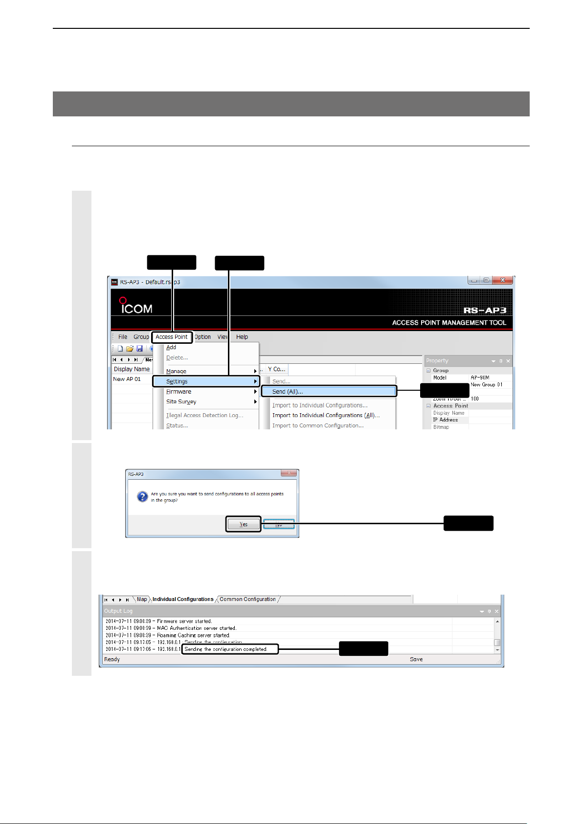
10. Sending the modified settings
To apply the setting contents modified with the RS-AP3, send the setting data to the managing access
points.
1
Click “Access Point” > “Settings” > “Send (All)...”
• You can select it from the menu that appears by right-clicking on the map screen.
• To individually send a setting data by each access point, select the access point on “Individual Configurations”
or on the map screen, and then click “Send...”
2
Click [Yes].
q Click
w Select
e Click
Click
3
When the setting data is sent, “Sending the configuration completed” appears.
• If “Failed to send the configuration” is displayed, check the access point connection of the IP address.
Check
1-19
Page 25
USING THE RS-AP3
2
3. Starting the RS-AP3
10. Sending the modified settings (Continued)
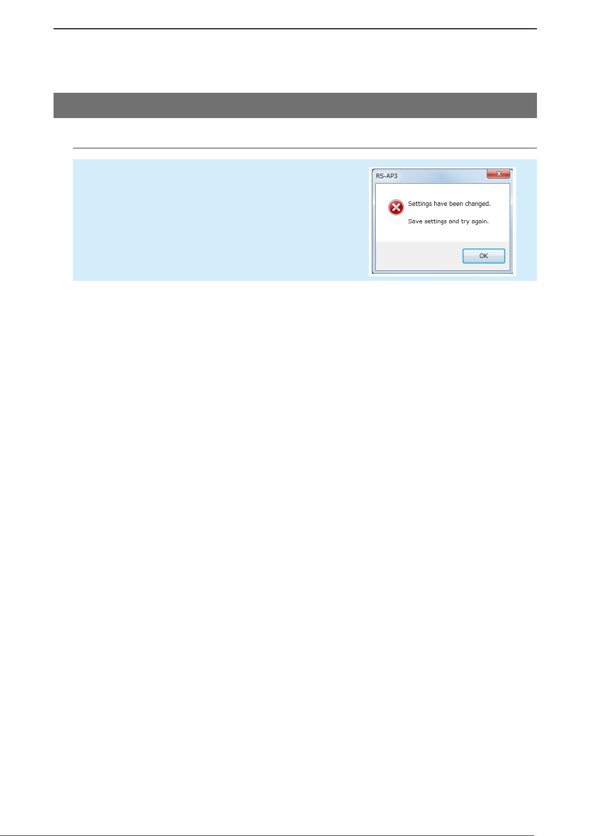
NOTE
Before you send the modified settings, you need to save them
first.
If the dialog to the right is displayed, click [OK] and then save.
(+p.1-18)
1-20
Page 26
USING THE RS-AP3
2
To continue the management on the Windows service, skip to the steps on page 1-23.
3. Starting the RS-AP3 (Continued)
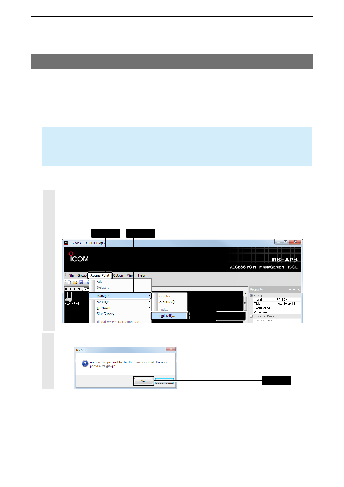
11. Ending the management
To close the operating screen and continue the management on the Windows service, skip to the steps on
page 1-23.
• The settings on the access point setting screen cannot be modified until the management is finished.
• If there are multiple groups to manage, finish the management one by one.
NOTE
When you finish the access point management, the management tool settings on the access points
automatically returns to “Disable.”
To start the management, you must “Enable” the “Access Point Management Tools.” (
+p.1-4)
1
Click “Access Point” > “Manage” > “End (All)...”
• You can select it from the menu that displays by right-clicking on the map screen.
• To end a setting data by access point, select the access point on “Individual Configurations” or on the map
screen, and then click “End...”
q Click w Select
e Click
Click [Yes].
2
1-21
Click
Page 27
USING THE RS-AP3
2
3. Starting the RS-AP3
11. Ending the management (Continued)
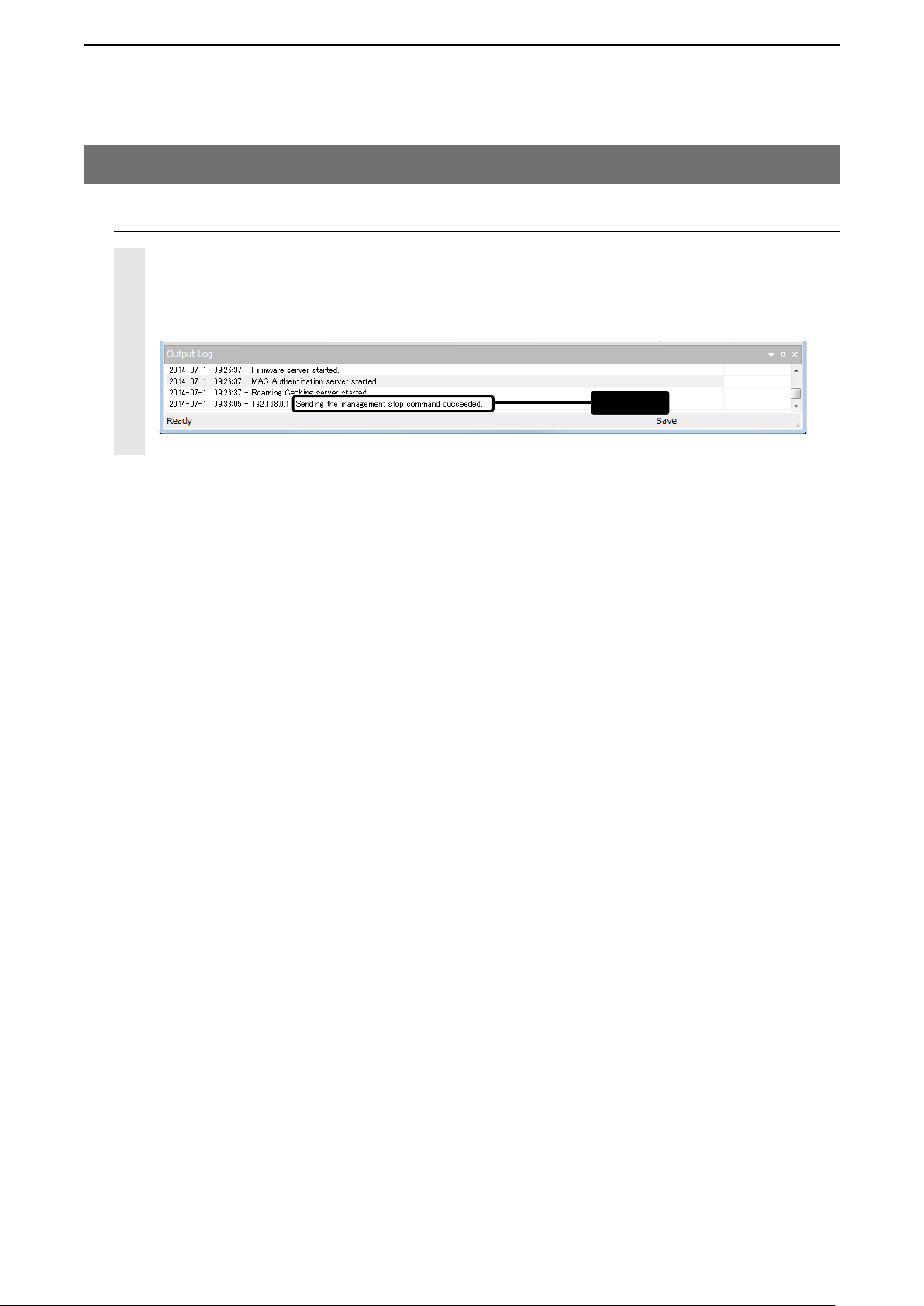
3
When the access point management is ended, “Sending the management stop command succeeded” displays.
• If “Failed in the management stop command” is displayed, check the connection for the access point of the its
IP address.
Check
1-22
Page 28
USING THE RS-AP3
2
3. Starting the RS-AP3 (Continued)
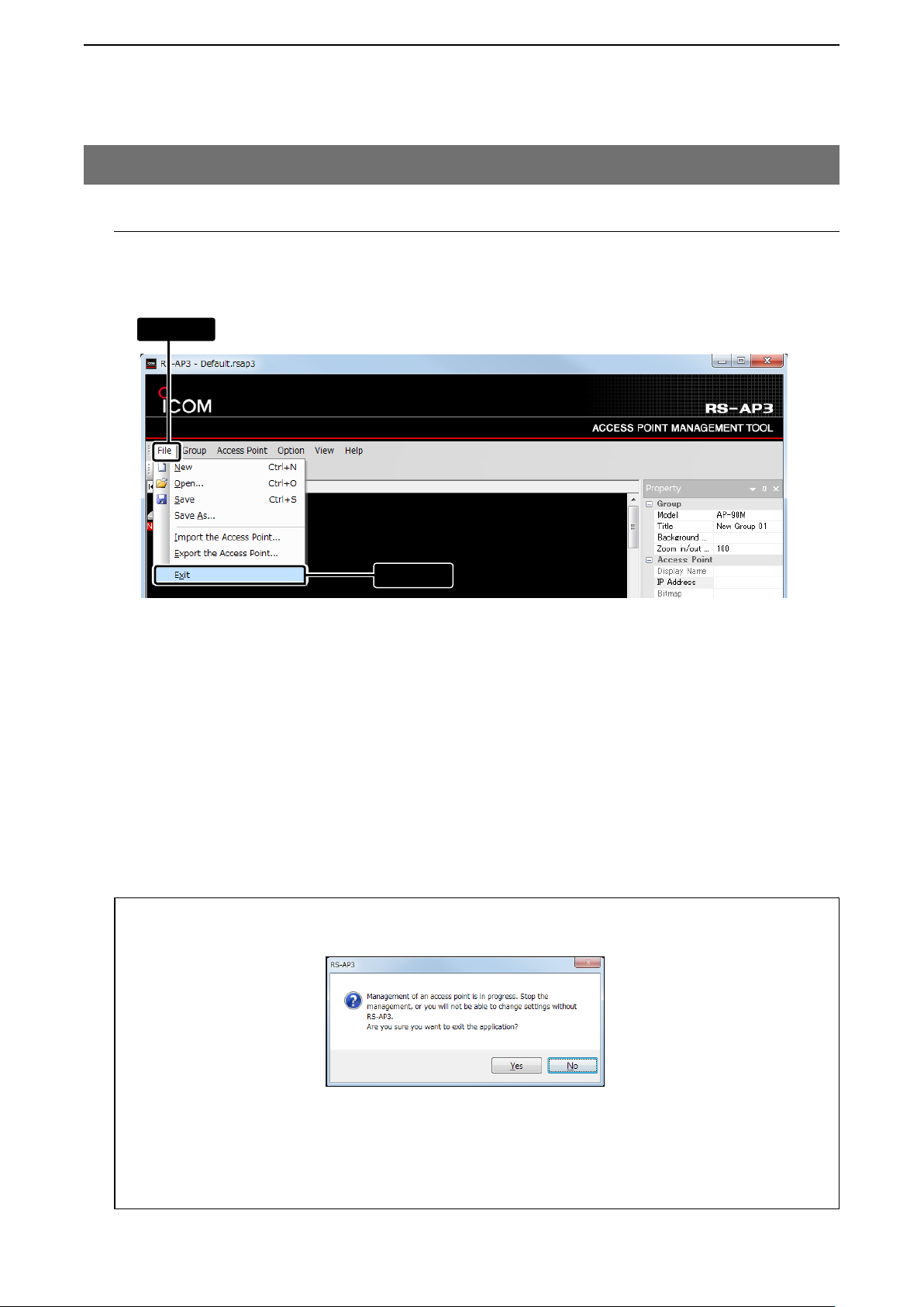
12. Closing the RS-AP3
Click “File,” and then “Exit” to close the RS-AP3.
• Clicking [X] also closes the RS-AP3.
q Click
w Click
If the management is not ended:
While managing an access point, and the “Exit” is selected, the dialog below appears.
• To continue the management, click [Yes].
➥ The RS-AP3 will close (Setting with other than the RS-AP3 is disabled.)
• To end the management:
1. Click [No], and then click “Access Point” > “Manage” > “End All...”
2. Click “File,” and then “Exit” to close the RS-AP3.
➥ If there are multiple groups to manage, finish the management one by one.
1-23
Page 29

OPERATING SCREEN
1. Screen description ………………………………………………………………………………………………… 2-2
2. Tool bar ……………………………………………………………………………………………………………… 2-3
3. Group tab and SYSLOG tab ……………………………………………………………………………………… 2-4
4. Map tab, Individual tab and Common tab ………………………………………………………………………… 2-5
5. Map screen ………………………………………………………………………………………………………… 2-6
Wireless access point title blinkings ……………………………………………………………………………… 2-7
6. Output Log screen ………………………………………………………………………………………………… 2-8
About the Log ……………………………………………………………………………………………………… 2-8
About the Output Log screen display …………………………………………………………………………… 2-8
7. Property screen …………………………………………………………………………………………………… 2-9
About the Property screen display …………………………………………………………………………… 2-11
8. SYSLOG screen ………………………………………………………………………………………………… 2-12
About the Filter …………………………………………………………………………………………………… 2-13
Log Folder setting ……………………………………………………………………………………………… 2-15
Opening SYSLOG ……………………………………………………………………………………………… 2-16
2
2-1
Page 30
OPERATING SCREEN
2
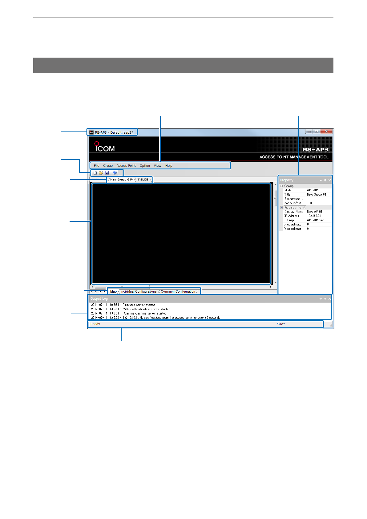
1. Screen description
Refer to the pages shown after the item for each operation displayed on the operation screen.
Title bar
(+p.1-12)
Tool bar
(+p.2-3)
Group tab/
SYSLOG tab
(+p.2-4)
Map screen
(+p.2-6)
Map tab/ Individual
Configurations/
Common Configuration tab (+p.2-5)
Menu Bar
(+p.3-1 to p.3-35)
Property screen
(+p.2-9 to p.2-10)
Output Log
screen
(+p.2-8)
Status bar
Displays explanations for the selected operation.
2-2
Page 31

OPERATING SCREEN
2
2. Tool bar
The Tool bar is used to create, open or save a new RS-AP3 setting file.
KqKwKeK
q New(Ctrl+N) ..............Creates a new document.
w
Open(Ctrl+O) ............ Opens an existing document.
• To open a document (extension: rsap3) saved with a different User ID and password,
e Save(Ctrl+S) ............ Saves the active document.
• When saving for the first time, you need to first name the document, then save it.
r
enter the ID and password you used when you saved the document, in the dialog
shown below.
r About ....................... Displays the program information, version number, and the copyright.
2-3
Page 32

OPERATING SCREEN
2
3. Group tab and SYSLOG tab
The tabs are used for access point management, or to check the SYSLOG.
q
K
When the [Group] tab (Example: New Group 01)
is clicked.
w
K
q Group tab ....................... When you want to manage networks by floors, you can divide the access
points into groups.
• Only the same model of access points can be managed in a group.
• To set the common configurations for a different access point, you need to separate
into different groups to manage.
• The group title can be changed in the “Property” screen. (
• The groups can be added or deleted by right-clicking the Group tab, or from the Group
menu. (
+p.3-3)
+p.2-9)
w SYSLOG tab ................... Displays the RS-AP3’s SYSLOG (log history.) (+p.2-12)
2-4
Page 33

OPERATING SCREEN
2
4. Map tab, Individual tab and Common tab
The tabs displayed on the operation screen when [Group] (example: New Group 01) is clicked.
q
K
q Map tab ................................................ Click to display the map screen. (+p.2-6)
It is used to add or manage access points.
w Individual Configurations tab ............ Click to display the Individual Configurations screen. (
It is used to set access points one by one.
e Common Configuration tab ............... Click to display the Common Configuration screen. (
It is used to set access points by groups.
w
K
e
K
+p.4-1)
+p.5-1)
2-5
Page 34

OPERATING SCREEN
2
5. Map screen
The screen allows you to add, delete and manage access points by selected groups.
Group tab/
(+p.2-4)
You can display the access point management
status by locating the cursor.
Access points can be added or deleted from the “Access Point” menu.
• You can also do the same from the menu displays by right-clicking on the map screen.
• To set the background, save the desired bitmap formatted (24 bit) image file in the “BG” folder that is located in the
same location where the RS-AP3 is installed. (+p.6-14)
2-6
Page 35

OPERATING SCREEN
2
5. Map screen (Continued)
Wireless access point title blinkings
The access point status blinks in colors.
Icon (example) Blinking color Status
• Communication not yet established.
• Management not started.
• No notifi cation from the access point for more than 60 seconds.
Red
Red
(Characters)
Yellow
Orange
• Rebooting.
• Firmware updating.
– When it blinks in red other than “No notifications from the access point for
over 60 seconds” is when the communication is not yet established.
This status is also applied when overwriting a fi le or starting the RS-AP3.
• The virtual AP is suspended by the network monitoring.
• Wireless is paused during the assigned wireless shutdown schedule.
• Wireless is paused because wireless 1 and 2 frequency bands (2.4 GHz/5GHz)
are set identically.
Detected illegal access.
• Checking for radar for DFS.
• The automatic control is enabled.
• Scanning channels as a wireless bridging client.
• Site surveying.
Grey
Purple
Blue
Firmware update is necessary.
• Despite the old and new version of the access point.
Discrepancy in the settings between the RS-AP3 and the access point.
• Besides settings, when the hash value is incorrect when importing the settings,
blinks in purple.
In this case, the setting data needs to be sent.
Sending the setting data.
2-7
Page 36

OPERATING SCREEN
2
6. Output Log screen
This screen displays the information on the server or the illegal access detection log history.
When the log saving setting (+p.3-27) is enabled, the log is displayed on the operation screen and saved
in the log file.
In total of 1000 lines can be displayed, and the older lines are automaitcally deleted.
About the Log
Right-click on the “Output Log” screen, the menu as shown below.
• To deselect the selected log, click the selected line while pushing [Ctrl].
About the Output Log screen display
Right-click on the “Output Log ( ),” the menu as shown below.
q
K
w
K
e
K
r
K
t
K
q Floating .......................... Displays only the “Log Output” screen.
w Docking .......................... The “Log Output” screen and the operation screen are combined.
(“Docking” is set as default)
e Tabbed Document ......... This menu is disabled at all times.
r Auto Hide ....................... Automatically hides the “Log Output” screen while not used.
t Hide ................................ Hides the “Log Output” screen.
• To display the “Log Output” screen, select “Log Output” in the “View” menu. (+p.3-34)
2-8
Page 37

OPERATING SCREEN
2
7. Property screen
The Property screen displays the title (Group name), background, selected access point name, and IP
address, and you can set them on this screen.
q
K
w
K
e
K
r
K
t
K
y
K
u
K
i
K
o
K
q Model .............................. Displays the selected group’s model.
w Title ................................. Displays the selected group’s title of up to 32 characters.
The title is also displayed on the Group tab.
(+p.2-4)
e Background Bitmap ...... A bitmap image file (24 bit color) saved in the “BG” folder can be set as the
background image.
• The “BG” folder is located in “Icom” > “RS-AP3” in the RS-AP3 installation folder.
• If the image is not located in the folder, this option cannot be selected.
(+p.6-14)
r Zoom in/out ................... Zooms in or out the background between 50~300 %.
t Display Name ................ Enter the display name of the access point selected on the map, of up to 32
characters.
• The entered name will display on the map screen and the “Individual Configuration”
screen.
y IP Address ..................... Displays the IP address set to the access point selected on the map screen.
• Make sure that the correct IP address is set, otherwise the management cannot be
started.
u Bitmap ............................ Select the access point icon to display on the map screen.
The bitmap automatically changes, depending on the model settings. (+p.1-7)
2-9
Page 38

OPERATING SCREEN
2
7. Property screen (Continued)
K
q
K
w
K
e
K
r
K
t
K
y
K
u
K
i
K
o
i X Coordinate .................. Displays and sets the access point icon’s horizontal coordination.
Set between 0 and 2048.
o Y Coordinate .................. Displays and sets the access point icon’s vertical coordination.
Set between 0 and 2048.
2-10
Page 39

OPERATING SCREEN
2
7. Property screen (Continued)
About the Property screen display
Click on the Property screen to display the screen as shown below.
q
K
w
K
e
K
r
K
t
K
q Floating .......................... Displays only the “Property” screen.
w Docking .......................... The “Property” screen and the operation screen are combined.
(“Docking” is set as default)
e Tabbed Document ......... This menu is disabled at all times.
r Auto Hide ....................... Automatically hides the “Property” screen while not used.
t Hide ................................ Hides the “Property” screen.
• To display the “Property” screen, select “
Property
” in the “View” menu. (+p.3-34)
2-11
Page 40

OPERATING SCREEN
2
8. SYSLOG screen
Click the “SYSLOG” tab to display the log information.
In total of 1000 lines can be displayed, and the older lines are automaitcally deleted.
• To save the log information, make sure “Option” > “Save Log” > “SYSLOG” is selected. (+p.2-15, p.3-27)
SYSLOG tab
p.2-4)
(+
• SYSLOG is saved separately by date and IP address (extension: txt), and also divided by approximately 64 KB files.
2-12
Page 41

OPERATING SCREEN
2
8. SYSLOG screen (Continued)
About the Filter
Right-click on the “SYSLOG” screen to extract the desired log information from “Filter.”
Extracting by “ Date and Time...”
q Right-click w Click
e Click
Extracting by “ Facility”
q Right-Click w Click e Click
r Select
2-13
+ Continued on the next page
Page 42

OPERATING SCREEN
2
8. SYSLOG screen
About the Filter (Continued)
Extracting by “Level”
q Right-click w Click e Click
2-14
Page 43

OPERATING SCREEN
2
8. SYSLOG screen (Continued)
Log Folder setting
Follow the instructions below to change the folder to save SYSLOG in.
q Click w Click
e Click
r Click
2-15
Page 44

OPERATING SCREEN
2
8. SYSLOG screen (Continued)
Opening SYSLOG
Right-click on the “SYSLOG” screen and select “Open” to open a SYSLOG file (extension: txt).
q Right-click w Click
e Select
r Click
2-16
Page 45

MENU
1. File menu …………………………………………………………………………………………………………… 3-2
2. Group menu ………………………………………………………………………………………………………… 3-3
3. Access Point menu ………………………………………………………………………………………………… 3-6
4. Option menu ……………………………………………………………………………………………………… 3-24
PMK Caching sharing function setting (Authentication/RADIUS) ……………………………………… 3-32
5. View menu ……………………………………………………………………………………………………… 3-34
6. Help menu ……………………………………………………………………………………………………… 3-35
3
3-1
Page 46

MENU
3
1. File menu
The File menu is used to create, open or save a new RS-AP3 setting file (extension: rsap3).
q
K
w
K
e
K
r
K
t
K
y
K
u
K
q New(Ctrl+N) ............................. Creates a new document.
w Open(Ctrl+O) ........................... Opens an existing document.
• To open a document (extension: rsap3) saved with a different User ID and password, you need to enter the ID and password you entered when you saved the
document, in the dialog shown below.
e Save(Ctrl+S) ............................ Saves the active document.
r Save As... ................................ Saves the active document with a new name.
t Import the Access Point... .... Imports access point information file (extension: csv) to the RS-AP3.
• If the information same as the registered access point is imported, the informa-
tion is overwritten.
• You can import only the file that is exported from [Export the Access Point]
(y).
y Export the Access Point... ....
• Access point information includes group and model title, access point IP ad-
• An exported file can be edited with a text editor.
u Exit ..........................................
The registered access point information can be exported (extension: csv)
dress, display name and coordinates (positioning) on the map screen.
Closes the RS-AP3
• Clicking [X] also closes the RS-AP3.
• To continue managing with the Windows service, save the changes and close
RS-AP3 operating screen.
3-2
Page 47

MENU
3
2. Group menu
The Group menu is used to add or delete a group.
• Only the same model access points can be managed in a group.
• To set the common configurations for a different access point, you need to separate into different groups to manage.
• While selecting the “SYSLOG” screen, [Delete...] is displayed in grey.
q Click
w Select
Selecting a group by right-clicking
q Right-click
w Select
3-3
Page 48

MENU
3
2. Group menu (Continued)
q
K
w
K
e
K
r
K
q Add........................................... Adds a group.
Click to display the “Add a group” dialog.
Select the access point model for the new group, and then click [OK].
w Delete ....................................... Deletes a selected group.
• The selected group’s access point information is also deleted.
• Confirm that the selected group and the access point information is deleted.
• While managing an access point, its settings cannot be modified on the access
point setting screen.
If you have mistakenly deleted a managing group, add a group and access
points and set them again.
Setting the Title (group name)/Background Bitmap
• If necessary, enter a title (group name) of up to 32 characters from the “Property” screen.
• Click “Background Bitmap” on the “Property” screen to select a 24 bit bitmap formatted image file saved in the “BG”
folder located in the RS-AP3 installed folder.
Refer to “Background bitmap setting” on page 6-14 for details.
The entered title (group name) displays.
Set
3-4
Page 49

MENU
3
2. Group menu (Continued)
q
K
w
K
e
K
r
K
e Security Dashboard ................ Displays the SSIDs and encryption settings for all the access points reg-
istered in the group in a list.
r Automatic Control .................. Displays the Automatic Control menu which configures the access points
in the same group, according to the setting environment.
• It is activated when “Option” > “Automatic” > “Automatic Control” > “Automatic
Control” is selected.
KKq
w
q Start... ................................ According to the scan results, the power level and the channel that applies
with the system enviroment are set to the access point.
To adjust the neighbor access point’s power level that has a disability,
you need to activate the Automatic Control beforehand.
•
• “Use Common Configuration” is selected in Wireless LAN in the Individual Con-
• Before starting the Automatic Control, start managing all the access points in
If adjustment has been modified, “(Auto)” displays in the power level, channel, or
access point status field (+p.2-6) on the “Status” screen (+p.3-19.)
figurations, and the access points with their transparent display names on the
map screen are subjected.
the group.
w Reset .................................. Returns the access point’s power level and channel modified by
the Automatic Control to the “Individual Configuration” or “Common
Configuration” screen contents.
3-5
Page 50

MENU
3
3. Access Point menu
The Access Point menu is used to add, delete, start or end the management of the access point, and to
update the firmware, detect illegal access and display the status, and so on.
• To manage access points one by one, select the access point on the map screen first, and then start the manage-
ment.
q Click
w Select
Selecting by right-clicking the wireless access point icon
q Right-click
w Select
3-6
Page 51

MENU
3
3. Access Point menu (Continued)
q
K
w
K
e
K
r
K
t
K
y
K
u
K
i
K
o
K
!0
K
!1
K
!2
K
!3
K
!4
K
q Add........................................... Adds an access point.
Select the added access point, and then enter the IP address.
• The access point without its IP address entered on the “Property” screen
cannot be managed with the RS-AP3.
• When the number of the access points has reached the maximum, this
option is greyed out.
w Delete... ...................................Deletes the selected access point.
• After deleting, confirm that the group is successfully deleted.
• A currently managing access point cannot be set on the access point’s setting
screen.
If you have deleted by mistake, add an access point and set it again.
e Manage .................................... Displays the access point management menu.
• The access point without its IP address entered on the “Property” screen
cannot be managed with the RS-AP3.
K
q
K
w
K
e
K
r
3-7
Page 52

MENU
3
3. Access Point menu
q
K
w
K
e
K
r
K
t
K
y
K
u
K
i
K
o
K
!0
K
!1
K
!2
K
!3
K
!4
K
e Manage (Continued) ...............
K
q
K
w
K
e
K
r
q Start... ......................................Starts managing the selected access point.
• Access points’ settings cannot be modified on the access point’s setting screen
until the management is finished.
w Start (All)... ..............................Starts managing all the access points in the group.
• If there are multiple groups to manage, start managing group by group.
e End... ........................................ Ends managing the selected access points.
r End (All)... ................................ Ends managing the access points in the selected group.
•
If there are multiple groups to manage, end managing group by group.
NOTE:
To start the access point management, you must “Enable” the “Access Point Management Tools.”
When you finish the access point management, the management tool settings on the access points
automatically return to “Disable.”
3-8
Page 53

MENU
3
3. Access Point menu (Continued)
q
K
w
K
e
K
r
K
t
K
y
K
u
K
i
K
o
K
!0
K
!1
K
!2
K
!3
K
!4
K
r Settings ................................... Displays the menu to export or import setting data to the managing ac-
cess points.
q
K
w
K
e
K
K
r
K
t
q Send... ...................................... Sends the setting data modified on the “Individual Configurations”
screen or “Common Configuration” screen to the selected access point.
+p.4-2, p.5-2)
(
w Send (All)... .............................. Sends the setting data modified on the “Individual Configurations” screen
or “Common Configuration” screen to the access points in the selected
group. (
+p.4-2, p.5-2)
e Import to Individual
Configurations... ..................... Imports the setting data on the “Individual Configurations” screen from
the selected acess point. (
+p.4-2)
r Import to Individual
Configurations (All)... ............. Imports the setting data on the “Individual Configurations” screen from
the acess points in the selected group. (
+p.4-2)
t Import to Common
Configuration... ....................... Imports the setting data on the “Common Configuration” screen from the
selected acess point. (
3-9
+p.5-2)
Page 54

MENU
3
3. Access Point menu (Continued)
K
q
K
w
K
e
K
r
K
t
K
y
K
u
K
i
K
o
K
!0
K
!1
K
!2
K
!3
K
!4
t Firmware ................................. Displays the menu to update the access point firmware.
• If the AP-90M’s firmware does not match the RS-AP3’s firmware, the access
point’s firmware automatically updates. (When “Option” > “Automatic” > “Firmware Update” is selected) (+p.3-24)
KKq
w
q Update... ..................................Updates the selected access point to the RS-AP3’s firmware.
w Update (All)... .......................... Updates the access points in the selected group to the RS-AP3’s
firmware.
3-10
Page 55

MENU
3
3. Access Point menu (Continued)
q
K
w
K
e
K
r
K
t
K
y
K
u
K
i
K
o
K
!0
K
!1
K
!2
K
!3
K
!4
K
y Site Survey .............................. Displays the Site Survey menu.
• The access point cannot communicate with the wireless LAN terminal during a
site survey.
q
K
w
K
e
K
r
K
t
K
y
K
u
K
q Start... ......................................Starts a site survey for the selected access point.
w Start (All)... .............................. Starts a site survey for the access points in the selected group.
e Delete Results... ...................... Deletes a selected access point’s site survey results.
r Delete Results (All)... .............. Deletes a site survey results of the access points in the selected group.
3-11
+ (Continued on the next page)
Page 56

MENU
3
3. Access Point menu
K
q
K
w
K
e
K
r
K
t
K
y
K
u
K
i
K
o
K
!0
K
!1
K
!2
K
!3
K
!4
y Site Survey (Continued) .........
q
K
w
K
e
K
r
K
t
K
y
K
u
K
t Display Results (Line) ............ Draws the site survey results in lines.
• The purple lines (+p.3-16) stand for the channel (frequency) used for commu-
nication, and the line type stands for the strength of the signal.
• The directions of the arrow indicate the signal’s direction.
3-12
The broken line indicates that the signal
is weak, and the thicker the line is, the
sronger the signal is.
+ (Continued on the next page)
Page 57

MENU
3
3. Access Point menu
K
q
K
w
K
e
K
r
K
t
K
y
K
u
K
i
K
o
K
!0
K
!1
K
!2
K
!3
K
!4
y Site Survey (Continued) .........
q
K
w
K
e
K
r
K
t
K
y
K
u
K
t Display Results (Line)
(Continued) ............................. After the site survey, clicking the access point icon while pushing [Shift]
will display only the indicating line of the access point’s transmitting signal
strength.
Click while
pushing [Shift]
3-13
+ (Continued on the next page)
Page 58

MENU
3
3. Access Point menu
K
q
K
w
K
e
K
r
K
t
K
y
K
u
K
i
K
o
K
!0
K
!1
K
!2
K
!3
K
!4
y Site Survey (Continued) .........
q
K
w
K
e
K
r
K
t
K
y
K
u
K
t Display Results (Line)
(Continued) ............................. After the site survey, clicking the access point icon while pushing [Ctrl] will
display the indicating line of the access point’s receiving signal strength.
Click while
pushing [Ctrl]
3-14
Page 59

MENU
3
3. Access Point menu
K
q
K
w
K
e
K
r
K
t
K
y
K
u
K
i
K
o
K
!0
K
!1
K
!2
K
!3
K
!4
y Site Survey (Continued) .........
q
K
w
K
e
K
r
K
t
K
y
K
u
K
y Display Results (List) ............. Displays the site survey results in a list.
BSSID The detected device’s “BSSID.”
Channel The detected device’s channel.
The strength of the received signal detected from the
RSSI
Mode
Security
SSID
device.
• Higher values indicate stronger signals.
If the detected device is a wireless access point, “AP”
appears, and if it is a wireless LAN terminal operated in
the ad hoc mode, “ADHOC” appears.
Displays the encryption and authentication protocols
that the detected device uses to communicate.
• When the system is “WEP RC4” or “OCB AES,” “WEP”
is displayed.
The detected device’s “SSID.”
3-15
Page 60

MENU
3
3. Access Point menu
K
q
K
w
K
e
K
r
K
t
K
y
K
u
K
i
K
o
K
!0
K
!1
K
!2
K
!3
K
!4
y Site Survey (Continued) .........
q
K
w
K
e
K
r
K
t
K
y
K
u
K
u Color Settings... ...................... Sets the display color of the frequencies used in the “Display Results
(Line).”
“Color Settings” window
Place check mark to display the frequency in a specified color line.
If a check mark is removed, the frequency is not displayed in a color line.
(Default: [✔] displayed)
3-16
Page 61

MENU
3
3. Access Point menu
K
q
K
w
K
e
K
r
K
t
K
y
K
u
K
i
K
o
K
!0
K
!1
K
!2
K
!3
K
!4
y Site Survey (Continued) .........
q
K
w
K
e
K
r
K
t
K
y
K
u
K
u Color Settings...(Continued) ..
“Colors” window
Click a color in the “Color Settings” window to display the “Colors” window,
and then change the color.
• Clicking [Default] resets to the default color.
Click
3-17
Page 62

MENU
3
3. Access Point menu (Continued)
K
q
K
w
K
e
K
r
K
t
K
y
K
u
K
Illegal access detected:
Display name blinks yellow
i
K
o
K
!0
K
!1
K
!2
K
!3
K
!4
u Illegal Access
Detection Log... ...................... When an illegal access has been detected, the display name of the
subject access point blinks in yellow.
Select the blinking access point, and then click “Illegal Access Detection
Log...” to stop the blinking and to display the “Illegal Access Detection Log”
screen
• To save the illegal access point log, place a check mark in “Illegal Access De-
(Option > Save Log > Illegal Access Detection Log)
• The RS-AP3 detects an illegal access when:
.
tection Log.”
➥The connection is rejected by the MAC address fi ltering system.
➥The connection is rejected by exceeding the maximum number of stations.
➥ A station is disconnected by a MIC failure (replay protection) in the WPA
authentication.
3-18
Page 63

MENU
3
3. Access Point menu (Continued)
K
q
K
w
K
e
K
r
K
t
K
y
K
u
K
i
K
o
K
!0
K
!1
K
!2
K
!3
K
!4
i Status... ................................... Displays the contents (IP address, channel, BSSID and so on) of the
selected access point being managed on the “Status” screen.
3-19
Page 64

MENU
3
3. Access Point menu (Continued)
K
q
K
w
K
e
K
r
K
t
K
y
K
u
K
i
K
o
K
!0
K
!1
K
!2
K
!3
K
!4
o List of Connected
Stations... ................................ Displays the information of the wireless LAN terminals communicating
with the selected access point (MAC Address, RSSI, Tx Rate and so on)
on the “List of Connected Stations” screen.
3-20
Page 65

MENU
3
3. Access Point menu (Continued)
K
q
K
w
K
e
K
r
K
t
K
y
K
u
K
i
K
o
K
!0
K
!1
K
!2
K
!3
K
!4
!0 Traffic Statistics... ................... Displays the communication traffic statistics in a graph by searching the
history log.
Kr
Kq
Kw
Ke
q Start date/time/period ............ Sets the starting date, time and period of the search.
Date: Directly enter or click [] to select from the calendar.
Time: Select between 00:00 and 23:00 (1 hour step.)
Period: Select between 1, 3, 6, 12 and 24 (hour.)
w Interface .................................. Displays the interface names and their colors.
When an interface is selected, the subject graph will display in bold lines.
e Graph ....................................... Displays the traffic of each interface in the graph.
The lines are distinguished in the colors on the interface list.
r [Display] .................................. Click to start searching and display on the graph.
3-21
Page 66

MENU
3
3. Access Point menu (Continued)
K
q
K
w
K
e
K
r
K
t
K
y
K
u
K
i
K
o
K
!0
K
!1
K
!2
K
!3
K
!4
!1 Wireless Analyzer... ................ Displays the surrounding radio wave environment in a graph based on
the data imported from the access point.
• The access points’ display names without colors on the map screen are the
analyzing targets.
• While analyzing, the analyzing access point cannot communicate with a wire-
less LAN terminal.
Radio wave intensity
color bar
High
Low
High
Low
Radio wave intensity
Present
Past
Horizontal axis: Frequency
Vertical axis: Signal strength
Time past
3-22
Page 67

MENU
3
3. Access Point menu
K
q
K
w
K
e
K
r
K
t
K
y
K
u
K
i
K
o
K
!0
K
!1
K
!2
K
!3
K
!4
!1 Wireless Analyzer
...(Continued) .......................... Channel
Select the scanning range of channels from the displayed list.
(Default: 001-005 CH (2412-2432 MHz))
Click
• The selectable channels differ, depending on the country.
!2 Lock Icons ............................... You can lock the access point icons on the map screen so that the they
will not relocate accidentally.
• To unlock, click to remove the check mark.
Click
!3 Restart... ................................. Restarts the selected access point.
!4 Restart (All)... ......................... Restarts all the access point in the selected group.
3-23
Page 68

MENU
3
4. Option menu
This menu is for automatic control, saving the log and so on.
K
q
K
w
K
e
K
r
K
t
K
y
q Automatic ................................ Displays the menu to select the automatic Firmware Update, Start
Management and so on.
K
q
K
w
K
e
K
r
q Firmware Update .................... If the firmware does not match the RS-AP3’s firmware, the access point’s
firmware automatically updates.
• Select to update the firmware as soon as a different version is detected by se-
lecting “At all times,” or assign the time to update the firmware by selecting the
time.
– The assigned time is synchronized with the time on your PC.
• If time is selected, a firmware update starts at the assigned time.
– When the firmware update does not complete during the assigned time, the
update is canceled.
– After updating the firmware, the setting data does not match with the RS-
AP3’s data. Therefore, the setting data needs to be sent to the access point.
(Option > Automatic > Settings Update) (+p.3-25)
If the firmware update and the settings update time are assigned in the same
hour, the firmware is updated first, and then the setting data is updated.
3-24
Page 69

MENU
3
4. Option menu (Continued)
q Automatic (continued) ...........
K
q
K
w
K
e
K
r
K
t
K
y
K
q
K
w
K
e
K
r
w Settings Update ...................... If the setting data does not match the RS-AP3’s setting data, it automati-
cally sends to the access point.
• Select to send the setting data as soon as a different data is detected by selecting “At all times,” or assign the time to send by selecting the time.
– The assigned time is synchronized with the time on your PC.
• If time is selected, the data is sent to update at the assigned time.
– When the updating does not complete during the assigned time, the updating
is canceled.
– This function can be used with the Firmware Update function.
(Option > Automatic > Firmware Update) (+p.3-24)
If the firmware update and the settings update time are assigned in the same
hour, the firmware is updated first, and then the setting data is updated.
3-25
Page 70

MENU
3
4. Option menu (Continued)
q Automatic (continued) ...........
q
K
w
K
e
K
r
K
t
K
y
K
K
q
K
w
K
e
K
r
e Start Management .................. If an access point that is not being managed is found, this option will
automatically start managing.
• “Access Point Management Tools” must be enabled, and the access point must
be located and set on the map screen to start its management.
r Automatic Control ..................Enables or disables the Automatic Control function.
• Select the channels that can automatically be controlled in the “Channel List.”
• If the function is enabled, “Automatic Control” in the “Group” menu is also en-
abled. (+p.3-5)
Channel List... Selects channels to be automatically controlled. Select one or
more channels each from the 2.4GHz and 5GHz channels.
• If the selected channels do not include the supported band-
width, the first channel which includes the supported bandwidth is automatically selected.
3-26
Page 71

MENU
3
4. Option menu (Continued)
q
K
w
K
e
K
r
K
t
K
y
K
w Save the Log ...........................
q Output Log ..............................
Displays the saving options for illegal access detection, SYSLOG and so on.
K
q
K
w
K
e
K
r
K
t
Saves the information on the server or the illegal access detection log history.
w Illegal Access
Detection Log ......................... Saves the received illegal access detection as a log.
e SYSLOG .................................. Saves the SYSLOG received when using the SYSLOG server in a file
(Extension: txt).
r Traffic Statistics ...................... Saves the traffic statistics as a log.
3-27
Page 72

MENU
3
4. Option menu (Continued)
w Save the Log (continued) .......
q
K
w
K
e
K
r
K
t
K
y
K
K
q
K
w
K
e
K
r
K
t
t Log Folder... ............................Sets the folder to save the logs and manages the stored log.
Log Management
Target: Click to check the logs to delete automatically.
Storing Period (days): Select number of days to keep the logs from “30,” “60,”
or “90.” (Default: 30 (days))
Delete All Traffic
Statistics Log: Click <Delete>, then click <Yes> to manually delete all
the traffic statistics logs except the current day, regard-
less of the “Storing Period (days)” setting.
Delete the Other Logs: Click <Delete>, then click <Yes> to manually delete all
of the output logs, illegal access detection logs, and
SYSLOG logs, except the current day, regardless of
the “Storing Period (days)” setting.
3-28
Page 73

MENU
3
4. Option menu (Continued)
q
K
w
K
e
K
r
K
t
K
y
K
e MAC Authentication
Server... ................................... You can register up to 10000 MAC addresses used for the MAC authen-
tication server (RADIUS.)
• The RS-AP3’s MAC Authentication Server function
(RADIUS) cannot be used as the VLAN authentication
server. (Attribute responder not supported)
• The following setting is when the RS-AP3 MAC authentication server is enabled
in the “MAC Authentication Server (RADIUS)” setting on the “Common Configu
ration” screen.
3-29
+ (Continued on the next page)
Page 74

MENU
3
4. Option menu
e MAC Authentication
Server...(Continued) ...............
q
K
w
K
e
K
r
K
t
K
y
K
KKq
w
KKe
r
q Import... ................................... Imports the MAC address information (extension: txt) to the RS-AP3.
• The previously registered MAC address will be overwritten.
• You can import only the file that is exported from [Export...] (w).
w Export... ................................... Exports the registered MAC address information as a text file (extension:
txt) to a desired location.
• The following MAC addresses are taken as identical.
(Example: 0090C7777777 and 00-90-C7-77-77-77)
e Enable Server ......................... Enables the RS-AP3’s MAC authentication server.
r Authentication Policy ............. Selects whether or not to allow to access from a wireless LAN terminal
that has its MAC address registered. (Default: Allow List)
Allow List: Allows to access from only the registered wireless LAN
terminals.
• All the terminals with MAC addresses that are not registered
are denied.
Deny List: Denies to access from only the registered wireless LAN
terminals.
• All the terminals with MAC addresses that are not registered
are allowed.
3-30
Page 75

MENU
3
4. Option menu (Continued)
q
K
w
K
e
K
r
K
t
K
y
K
r Roaming Caching... ................ Enables the PMK (Pairwise Master Key) Caching function that minimizes
the communication interruptions by leaving out some parts of the authentication, when the wireless LAN terminal roams to other access points.
• The PMK Caching function can be used when “WPA2” or “WPA/WPA2” authen-
tication is used.
RS-AP3
e
Authorized by the
RADIUS server
RADIUS server
w
Access point A
accessing the RADIUS server
Wireless LAN terminal
Sends PMK Caching
r
to the RS-AP3
Wireless access
point A
If there is a correct
i
PMK Caching, skips
the authentication,
and enables
connection.
Accessing access point A
q
t
Moving
Wireless LAN terminal
If you receive caching information
u
while changing to access point B
by roaming, it will not communicate
withthe RADIUS server and checks
for the PMK caching with the RS-AP3.
Wireless access
point B
NOTE
• All the PMK cachings are deleted when the setting data is saved to the RS-AP3.
• Up to 16 PMK cachings can be held in each wireless LAN.
When the amount of the PMK cachings exceed more than 16, the older PMK cachings are deleted.
Also, the PMK cachings that exceed the PMK Caching Timeout are deleted. (+p.3-30)
When accessing
y
access point B,
sends the caching
information from
accessing the acces
point A.
3-31
+ (Continued on the next page)
Page 76

MENU
3
4. Option menu
r Roaming Caching...
(Continued) .............................
q
K
w
K
e
K
r
K
t
K
y
K
KKq
w
q Roaming Caching ................... Enables or disables the Roaming Caching function.
(Default: Enable)
w PMK Caching Timeout
(minute) ................................... If necessary, set the timeout period until the PMK caching is automati-
cally deleted.
• Set the period between 1 and 1440 minutes. (Default: 720)
PMK Caching sharing function setting (Authentication/RADIUS)
In the Wireless Settings on the “Common Configuration” screen, Set “WPA2,” or “WPA/WPA2,” and the RADIUS
server. (As shown in the screen below)
To apply the changes, overwrite the settings, and then send the setting data to the access points. (+p.1-18 to p.1-20)
3-32
Page 77

MENU
3
4. Option menu (Continued)
q
K
w
K
e
K
r
K
t
K
y
K
t Email... ..................................... Displays the “Email Settings” window to send access point information by
email.
• Refer to “Notification by email function” on page 6-2 of this manual for more
details.
y Mirroring... ............................... Displays the Mirroring function menu.
K
q
K
w
K
e
Having the Mirroring function enabled will avoid being disabled by inter-
ferences.
If you enable, the setting data on this PC is synchronized with another
PC with the RS-AP3.
• Refer to “To prevent the management inability” on page 6-7 for the setting de-
tails.
q Status... ................................... Displays the “Mirroring Status” window after enabling the mirroring func-
tion to confirm the setting options that are not synchronized. (+p.6-13)
• Double-clicking “Synchronized” or “Unsynchronized” will also display the win-
dow.
w Options... ................................. Displays the “Mirroring Option” window to set the mirroring function.
(+p.6-8)
e Synchronize... ......................... Displays the “ Mirroring” window to synchronize the Primary and the Sec-
ondary settings after enabling the mirroring function. (+p.6-10)
3-33
Page 78

MENU
3
5. View menu
This menu is for the RS-AP3’s view settings.
Caption Bar
Tool Bar
q
K
w
K
e
K
r
K
t
K
Property
Output Log
Status Bar
q Caption Bar ............................. Set whether or not to display the caption bar.
w Tool Bar ...................................Set whether or not to display the tool bar.
e Status Bar ............................... Set whether or not to display the status bar.
r Output Log .............................. Set whether or not to display the “Output Log” screen.
t Property ................................... Set whether or not to display the “Property” screen.
3-34
Page 79

MENU
3
6. Help menu
This menu displays the RS-AP3’s instruction manual (this manual) and the version information.
q
K
w
K
q Manual ..................................... Opens this instruction manual.
w About ....................................... Displays the software, version and copyright information.
3-35
Page 80

INDIVIDUAL CONFIGURATIONS
1. Operating …………………………………………………………………………………………………………… 4-2
2. IP Address …………………………………………………………………………………………………………… 4-3
Setting the Host Name …………………………………………………………………………………………… 4-3
3. DHCP Server ……………………………………………………………………………………………………… 4-4
4. Packet Filter ………………………………………………………………………………………………………… 4-5
Packet Filter Import/Export function ……………………………………………………………………………… 4-6
5. Wireless Settings …………………………………………………………………………………………………… 4-7
When using the Wireless Bridging function …………………………………………………………………… 4 -7
6. SNMP ………………………………………………………………………………………………………………… 4-8
7. Command …………………………………………………………………………………………………………… 4-9
4
4-1
Page 81

INDIVIDUAL CONFIGURATIONS
4
1. Operating
Click the “Individual Configurations” tab to display the access points in the selected group.
Select an access point, and then change the settings. (+p.4-3 to p.4-9)
• To apply the changes, overwrite the settings, and then send the setting data to the access points.
(+p.1-18 to p.1-20)
w Selectr Save e Check
The settings on the “Property” screen can also be
set on this list. (
+p.2-9)
q Click
4-2
Page 82

INDIVIDUAL CONFIGURATIONS
4
2. IP Address
Set “Host Name” and “Management VLAN ID” of the selected access point.
• To apply the changes, overwrite the settings, and then send the setting data to access points.
(+p.1-18 to p.1-20)
• Refer to the instruction manual (PDF) or online help for Icom’s access point setting details.
Setting the Host Name
Enter a desired host name of up the 31 characters (a to z, A to Z, 0 to 9 and - (hyphen)).
A name starting or ending with a “-” (hyphen) cannot be registered.
4-3
Page 83

INDIVIDUAL CONFIGURATIONS
4
3. DHCP Server
Set “DHCP Server” and “Static DHCP” for the selected access point.
• To apply the changes, overwrite the settings, and then send the setting data to access points.
(+p.1-18 to p.1-20)
• Refer to the instruction manual (PDF) or online help for Icom’s access point setting details.
4-4
Page 84

INDIVIDUAL CONFIGURATIONS
4
4. Packet Filter
Set “Packet Filter” for the selected access point.
• To apply the changes, overwrite the settings, and then send the setting data to access points.
(+p.1-18 to p.1-20)
• Refer to the instruction manual (PDF) or online help for Icom’s access point setting details.
Click a Packet Filter number (Entry) to
set “Use Common Configuration,” “Disable” or “Enable” to whether or not to use
a programmed filter.
(Default: Use Common Configuration)
4-5
+ (Continued on the next page)
Page 85

INDIVIDUAL CONFIGURATIONS
4
4. Packet Filter (Continued)
Packet Filter Import/Export function
The “Import/Export/Use Common Configuration for All/Delete All” option can only be used when the RSAP3 is used with Icom’s access points.
The import, export, and packet filter settings can be simultaneously set to the selected access points.
Exporting
q
Exports the programmed packet filter as a text file (extension: txt.)
1. ……………………………………………………………………………………………………………
Select “Export.”
………………………………………………………………………………………………………………
• When no packet filter is programmed, “No settings to export.” is displayed.
2. ……………………………………………………………………………………………………………
Set a desired file name, and then click [Save].
………………………………………………………………………………………………………………
• The exported file can be edited with a text editor.
Importing
w
Imports exported files.
1. ……………………………………………………………………………………………………………
Select “Import.”
2. ……………………………………………………………………………………………………………
Select a file for the packet filter, and then click [Open].
3. ……………………………………………………………………………………………………………
Click [OK].
………………………………………………………………………………………………………………
• The existing packet filter is overwritten.
………………………………………………………………………………………………………………
• You can import only the file that is exported from [Export].
Setting all packet filters
e
1. ……………………………………………………………………………………………………………
Select “Use Common Configuration for All” or “Delete All.”
2. Click [Yes] to set or delete all packet filters that are programmed to the selected access
points.
4-6
Page 86

INDIVIDUAL CONFIGURATIONS
4
5. Wireless Settings
Set “Wireless Unit,” “Channel,” “Power Level” and so on for the selected access point.
• When “Frequency Band” is set to “Use Common Configuration,” “Bandwidth,” “Channel” and “Power Level” cannot be
set.
• To apply the changes, overwrite the settings, and then send the setting data to access points.
(+p.1-18 to p.1-20)
• Refer to the instruction manual (PDF) or online help for Icom’s access point setting details.
When using the Wireless Bridging function
1. Before enabling the access point management tools, set the Wireless Bridging function on the access
point’s setting screen.
2. Before starting the management of the contents set in the step 1, set the “Individual Configurations”
screen.
When the Wireless Bridging is interrupted by setting modifications, the monitoring or setting modifications for the
target access point are disabled.
To modify the “Wireless Bridging” settings, start modifying from the access points that can only be communicated
with the Wireless Bridging function.
• When using the Wireless Bridging function with the Wireless 2 (external antenna’s LAN unit) on the AP-90M, the
virtual AP on the “Common Configuration” also must be set.
Refer to the AP-90M instruction manual for more details.
4-7
Page 87

INDIVIDUAL CONFIGURATIONS
4
6. SNMP
Set “System Location” and “System Contact” for the SNMP (Simple Network Management Protocol.)
• To apply the changes, overwrite the settings, and then send the setting data to access points.
(+p.1-18 to p.1-20)
• Refer to the instruction manual (PDF) or online help for Icom’s access point setting details.
4-8
Page 88

INDIVIDUAL CONFIGURATIONS
4
7. Command
The Command function is an expansion setting for the access point updates.
• This option is not used as of May 2017.
4-9
Page 89

COMMON CONFIGURATION
1. Operating …………………………………………………………………………………………………………… 5-2
2. Model ………………………………………………………………………………………………………………… 5-3
Changing the model ……………………………………………………………………………………………… 5-3
3. Network Settings …………………………………………………………………………………………………… 5-4
Web Authentication (Advanced) ………………………………………………………………………………… 5-5
4. Wireless Settings …………………………………………………………………………………………………… 5-6
Setting the MAC address filtering ………………………………………………………………………………… 5-7
Setting the schedule ……………………………………………………………………………………………… 5-9
5. Management ……………………………………………………………………………………………………… 5-10
6. Command ………………………………………………………………………………………………………… 5-11
7. Load Balancing …………………………………………………………………………………………………… 5-12
5
5-1
Page 90

COMMON CONFIGURATION
5
1. Operating
Click “Common Configuration” to display the configuration options to be commonly shared in the selected
group.
If you change settings, the same settings are made to all the access points in the group.
(+p.5-3 to p.5-10)
• To apply the changes, overwrite the settings, and then send the setting data to access points.
(+p.1-18 to p.1-20)
• The Individual Configurations have higher priority over the Common Configuration. (+p.4-1)
e Save w Set
5-2
q Click
Page 91

COMMON CONFIGURATION
5
2. Model
Check the model of the access point assigned to the selected group.
Changing the model
To change the model that was selected when you created the group (+p.1-7), click on the model name, and
then select from the drop down list.
• To apply the changes, overwrite the settings, and then send the setting data to the access points.
(+p.1-18 to p.1-20)
• Refer to the instruction manual (PDF) or online help for Icom’s access point setting details.
5-3
Page 92

COMMON CONFIGURATION
5
3. Network Settings
Set “Static Routing,” “Packet Filter” and so on to be commonly shared in the selected group.
• To apply the changes, overwrite the settings, and then send the setting data to the access points.
(+p.1-18 to p.1-20)
• Refer to the instruction manual (PDF) or online help for Icom’s access point setting details.
With the “Import/Export/Delete All” option, you can import, export or delete all packet filters. (+p.4-5)
To delete all entries, select “Delete All.”
Click a packet filter number to select whether or not to use the entry. (Default: Disable)
+ (Continued on the next page)
5-4
Page 93

COMMON CONFIGURATION
5
3. Network Settings (Continued)
Web Authentication (Advanced)
The “Import/Export/Delete All” option can only be used when the RS-AP3 is used with Icom’s access points.
You can import, export or delete all the entries on the local list on each virtual access point (interface.)
Exporting
q
Exports the programmed local list as a text file (extension: txt.)
1. Select “Export.”
• When no local list is programmed, “No items to export in the Local List.” is displayed.
2. Set a desired file name, and then click [Save].
• The exported file can be edited with a text editor.
Importing
w
Imports exported files.
1. Select “Import.”
2. Select a file for the local list, and then click [Open].
3. Click [OK].
• The existing local list is overwritten.
• You can import only the file that is exported from [Export].
Deleting all local lists
e
1. Select “Delete All.”
2. Click [Yes] to delete all the local list that are registered in the selected virtual access point.
5-5
Page 94

COMMON CONFIGURATION
5
4. Wireless Settings
Set “Bandwidth,” “Channel,” “Power Level” and so on to be commonly shared in the selected group.
• To apply the changes, overwrite the settings, and then send the setting data to wireless access points.
(+p.1-18 to p.1-20)
• Refer to the instruction manual (PDF) or online help for Icom’s access point setting details.
5-6
+ (Continued on the next page)
Page 95

COMMON CONFIGURATION
5
4. Wireless Settings (Continued)
Setting the MAC address filtering
The “Import/Export/Delete All” option can only be used when the RS-AP3 is used with Icom’s wireless access points.
You can import, export or delete all the MAC addresses on each virtual access point (interface.)
Exporting
q
Exports the programmed MAC addresses as a text file (extension: txt.)
1. Select “Export.”
• When no MAC address is programmed, “No MAC address to export.” is displayed.
2. Set a desired file name, and then click [Save].
• The exported file can be edited with a text editor.
• The following MAC addresses are taken as identical address.
(Example: 0090C7777777 and 00-90-C7-77-77-77)
Importing
w
Imports exported files.
1. Select “Import.”
2. Select a file for the MAC address, and then click [Open].
3. Click [OK].
• The existing MAC address is overwritten.
• You can import only the file that is exported from [Export].
Deleting all MAC addresses
e
1. Select “Delete All.”
2. Click [Yes] to delete all the MAC addresses that are registered in the selected virtual access point.
5-7
Page 96

COMMON CONFIGURATION
5
4. Wireless Settings (Continued)
Setting the interference filtering
The “Interference Filtering” options can only be used when the RS-AP3 is used with Icom’s wireless access
points.
The communication status is improved when a signal interference is found.
You can set the threshold level and the function to each wireless unit.
• The effects may differ, depending on the environment.
• It is not necessary to always have the RS-AP3 connected after setting the filtering because it is controlled on the wireless access point side.
Threshold level
Select the filtering threshold level between “High,” “Middle,” and “Low.” (Default: Disable)
The filtering is more sensitive while the threshold level is set to “Low.”
Stream number control
Select “Enable” to change between 2 streams and 1 stream. (Default: Disable)
5-8
Page 97

COMMON CONFIGURATION
5
4. Wireless Settings (Continued)
Setting the schedule
The “Schedule” options can only be used when the RS-AP3 is used with Icom’s wireless access points.
You can set the day and the time for wireless shut down in up to 16 different ways to each wireless unit.
• The time is synchronized with the time set to the access point.
We recommend that you enable the NTP function.
• It is not necessary to always have the RS-AP3 connected after setting the schedule because it is controlled on the
wireless access point side.
Set the wireless shutdown day and the time as shown above.
For example, if “Fri 23:00 - 06:00” is set, the wireless system is shutdown from Friday at 23:00 to Saturday
at 06:00. When the shutdown time and the end time are set at same time (example: “00:00 - 00:00” or “12:34
- 12:34”), the wireless system is shutdown for 24 hours.
5-9
Page 98

COMMON CONFIGURATION
5
5. Management
Set “Administrator,” “SYSLOG,” “SNMP” and so on to be commonly shared in the selected group.
• To apply the changes, overwrite the settings, and then send the setting data to the access points.
(+p.1-18 to p.1-20)
• Refer to the instruction manual (PDF) or online help for Icom’s access point setting details.
5-10
Page 99

COMMON CONFIGURATION
5
6. Command
The Command function is an expansion setting for the access point updates.
• This option is not used as of May 2017.
5-11
Page 100

COMMON CONFIGURATION
5
7. Load Balancing
The Load Balancing function, that is commonly shared in the selected group, can be used only when Icom’s
wireless access points and the RS-AP3 are used together. (Default: Disable)
If you “Enable” the Load Balancing setting, this function distributes the loadings according the status of the access points or wireless LAN terminals that is included in the regularly received information.
• If “Disable” is selected, the Load Balancing function will not distribute loadings, even if the operating conditions are satisfied.
• In order to control the Load Balancing function, the RS-AP3 needs to be connected at all times.
Operating Conditions
If either the amount of connected wireless LAN terminals or the communication volume, or both reach the conditions, the half of the connected wireless LAN terminals will be cut off.
• Amount of wireless LAN terminals may differ depending on the Maximum Number of Stations settings.
Maximum Number
of Stations
5 or less 6 to 29 30 or more
Amount of wireless LAN
terminals connected to the
virtual AP
• When a virtual AP has communicated continuously with more than 96 Mbps speed for more than 30 seconds.
No limitation by
amount
1 less than the set Maximum
Number of Stations
Fixed 30, regardless of the
Maximum Number
of Stations
Operation
The half of the connected wireless LAN terminals will be cut off in order of the weakest signal, and re-connection
will be inhibited for 60 seconds.
Example:
While the Balance Loading function is enabled and 9 wireless LAN terminals are connected to the Virtual AP
with Maximum Number of Stations set to 10, cuts off 4 connected wireless LAN terminals in order of the weakest
signal, and re-connection will be inhibited for 60 seconds.
5-12
 Loading...