

Page 1
q Horse band (HAS-40)............................................... 2
w Extention pipe (2273 pipe)......................................... 1
e DGPS receiver......................................................... 1
INSTRUCTION MANUAL
DIFFERENTIAL GPS BEACON RECEIVER
RD-200
Thank you for purchasing the RD-200 DIFFERENTIAL GPS BEACON RECEIVER. Connecting this
DPGS beacon receiver to the Icom navigation systems, will permit the GPS to pinpoint the ship location more accurately. Please read these instructions
thoroughly before installing and operating the RD-
200.
SUPPLIED ACCESSORIES
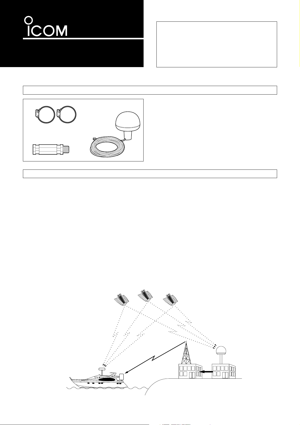
The Differential GPS (DGPS) is a system where the GPS positioning precision is advanced, and can be utilized efficiently
for coastal maneuvers or other times where high precision
positioning is vital. In order for the DGPS to be put into practice, a reference station has to be established in close proximity, and a Differential responding GPS ship navigation
system (sold separately) is to be installed.
The reference station (generally a radio beacon station already established) may assign true or arbitrary position readings due to false calculations of coordinates received from
the GPS receiver and coordinates that have been previously
received at the reference station. In this case, correct positional data is produced and this data (RTCM SC-104) is sent
out from the beacon transmitter.
For the operators, the position correction data is received at
the Differential GPS beacon receiver and then transferred to
the ship’s navigation system. By receiving this new and correct positioning data the ship’s GPS navigation system will
not only decrease the number of accidental errors, but will
also improve the positioning precision.
With the reference station and the remote receiver in close
proximity precision is at a high level, but by increasing this
distance the error count will increase. For the DGPS to coordinate correctly a distance of 100 to 200 miles is the most
accurate range limit.
(In reference with RTCM: Radio Technology
Commission for Maritime Services).
WHAT IS DIFFERENTIAL GPS ?
q
e
w
GPS Receiver
DGPS beacon
station
Position
corrections
Reference
station
GPS receiver
Beacon
receiver
Satellite
- 1 -
Page 2
DGPS
18.0 m
CLR
SET
SET
CANC
H
0
10
20
30
40
ADJ SEL
GPS 34°18.000N 135°01.000E
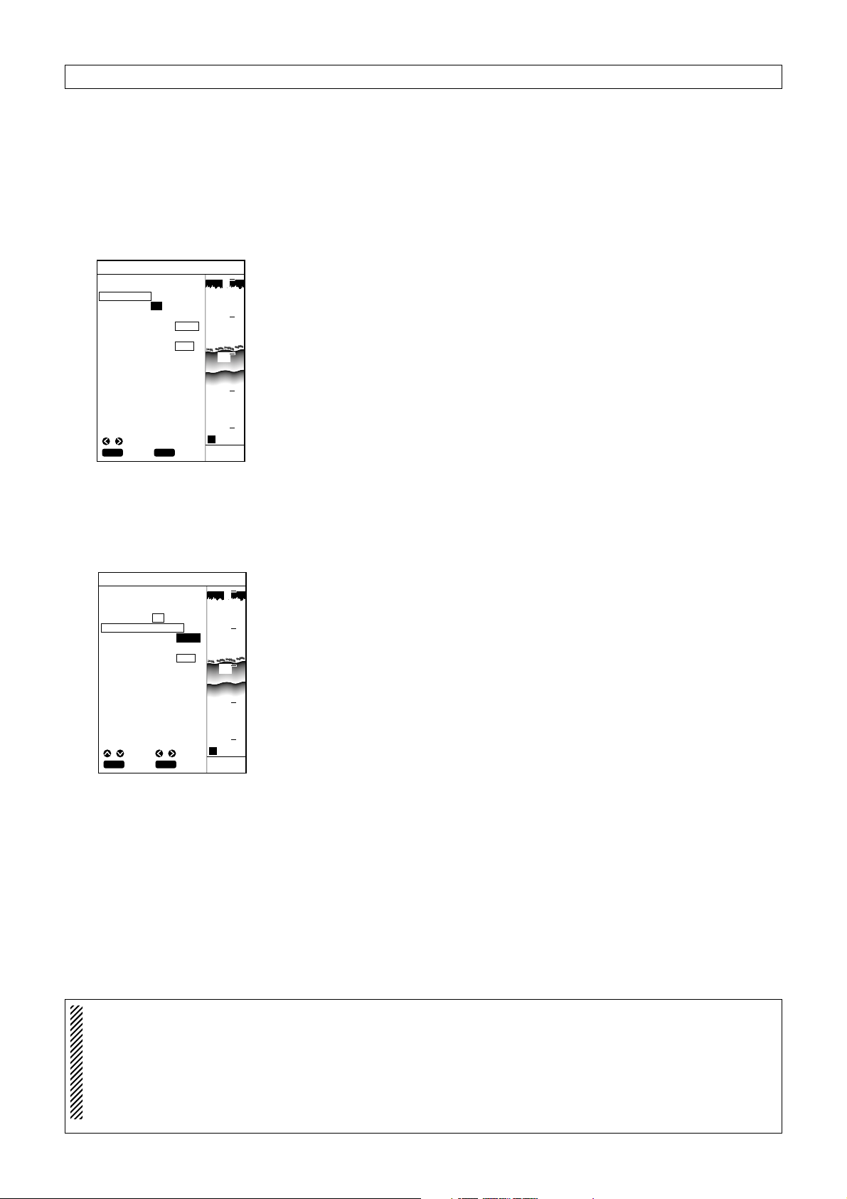
USING DGPS
ON OFF
BEACON FREQUENCY
283.5KHZ AUTO
BEACON BAUD RATE
100 200
OPERATION
The DPGS is a newly established system intended to improve the positioning precision of the GPS. (Optional RD-200 is
required).
This chapter describes how to correct the positioning data using DGPS data, select the beacon station, and set the baud rate.
When you activate the marine plotter (e.g. Icom FP-561) either of two screens will be displayed. The Plotter screen or the
Sounder screen. All functions are able to be accessed and activated from these two screens.
(1) Using the DGPS
(2) Setting the beacon
frequency and baud rate
DGPS
18.0 m
CLR
SET
SET
CANC
SEL
H
0
10
20
30
40
GPS 34°18.000N 135°01.000E
USING DGPS
ON OFF
BEACON FREQUENCY
283.5KHZ AUTO
BEACON BAUD RATE
100 200
To set the beacon frequency and baud rate (transmission speed), proceed as
follows.
q Press the [MENU] key.
The Main Menu screen will appear.
w Select “Positioning Menu” screen using the [UP] or [DOWN] key and press the
[SET] key.
The Positioning Menu screen will appear.
e Select “DGPS” using the [UP] or [DOWN] key and press the [SET] key.
The DGPS setting screen will appear.
r Select “Beacon Frequency” using the [UP] or [DOWN] key and press the [SET]
key.
AUTO (default) will turn yellow.
t Select the frequency field using the [LEFT] key. (See NOTE)
y Set the frequency using the [UP] or [DOWN] key and press the [SET] key.
• Set the frequency of the beacon station nearest to the current ship position.
(Refer to the supplied Beacon Station Lists.)
u When the frequency fields have been set, select “beacon baud rate” using the
[UP] or [DOWN] key and press the [SET] key.
The selected item turns blue.
i Select “100” or “200” using the [LEFT] or [RIGHT] key and then press the [SET]
key. The beacon baud rate will be set as you selected.
• If the Frequency of the beacon station has been set manually the baud rate of
the beacon station must also be entered manually. (See NOTE)
o When you finish setting the beacon frequency and baud rate, press the [MENU]
key.
You will return to the previous screen.
Using the DPGS data allows correction of the positioning data received by the
built-in GSP receiver.
q Press the [MENU] key.
The Main Menu screen will appear.
w Select “Positioning Menu” using the [UP] or [DOWN] key and press the [SET]
key.
The positioning screen will appear.
e Select “DGPS” using the [UP] or [DOWN] key and press the [SET] key.
The DGPS setting screen will appear.
r Select “Using DGPS” using the [UP] or [DOWN] key and press the [SET] key.
The selected item turns blue.
t Select “ON” using the [LEFT] key and press the [SET] key. (default: OFF)
The selection is now saved.
y When you finish setting, press the [MENU] key.
You will return to the previous screen.
NOTE: Generally when setting the beacon frequency please select the ”AUTO” option (as in step t). This will
automatically select the highest (closest) signal intensity to the ship's present position. If the system fails to
synchronize with this beacon station for one minute, it automatically starts to search for the highest signal intensity, again.
In cases where the beacon frequency has been manually selected after referral to the supplied BEACON STA-
TION LIST, ensure the corresponding baud rate is also entered. If both the beacon frequency and the baud
rate are not correctly entered the position correction signal will not be received.
- 2 -
Page 3

RD-200
DIFFERENTIAL GPS
RECEIVER
DGPS
Icom MARINE PLOTTER;
e.g. FP-561
As an alternative the Ratchet Mount is
available (sold separately.) Insert the
Ratchet mount into the base of the
RD-200 and screw in a clockwise direction to a firm but loose position.
CONNECTION
INSTALLATION
Horse bands
(supplied)
Ratchet mount
(Sold separately.
Ask your boat
dealer or marina.)
1 in (14 threads)
Prior to any operation it is important to make sure that all connections are performed accurately. All
connections should be performed
only by certified persons.
The output connector is to be connected from the RD-200 to Icom Marine Plotter DGPS data input terminal.
The supplied extended pipe is to be
inserted firmly into the base of the Differential GPS Receiver and screwed
in a clockwise direction.
Using the supplied Horse bands the
Differential GPS receiver can be stabilized to your designated area.
NOTE: The Ratchet mount is of a
metallic property and if inserted too
tightly the RD-200’s output cable
may be damaged or even cut. While
inserting the Ratchet mount it is advised to loosely maneuver the output
cable.
- 3 -
Page 4

SPECIFICATIONS
6-9-16 Kamihigashi, Hirano-ku, Osaka 547-0002 Japan
Count on us!
A-8335H-1EX-q Printed in Japan
© 1999 Icom Inc.
GENERAL
RECEIVER
• Frequency coverage
• Type of emission
• Antenna impedance
• Intermediate frequency
• Operating temperature range
• Power supply voltage
• Current drain (max.)
• Dimensions
• Weight
: 283.5 kHz to 325.0 kHz (0.5 kHz step)
: 1K0F2B
: 50 ohms nominal
: 455 kHz
: – 20
o
C to +70 oC, (– 4 oF to +158 oF)
: 12 V DC nominal (negative ground)
: 0.2 A
: 140 mm (D) x 157.2 mm (H) (5.5 in (D) x 6.2 in (H))
: 1.0 kg (2.2 lb)
• Sensitivity
• Sprious response
• Intermodulation
: – 14 dBµ (PD)
: 60 dB
: 50 dB
All specifications are subject to change without notice or obligation.
Versions of the RD-200 which display the “CE”
symbol on the serial number seal, comply with
the essential requirements of the 89/336/EEC
directive for Electromagnetic Compatibility.
Page 5

documentation manual, user maintenance, brochure, user reference, pdf manual
This file has been downloaded from:
User Manual and User Guide for many equipments like mobile phones, photo cameras, monther board, monitors, software, tv, dvd, and othes..
Manual users, user manuals, user guide manual, owners manual, instruction manual, manual owner, manual owner's, manual guide,
manual operation, operating manual, user's manual, operating instructions, manual operators, manual operator, manual product,
 Loading...