

Page 1
INSTRUCTIONS
e r t
w
q
OFF
ON
PS-250
DC DC POWER SUPPLY
-
wq
q w e
DC-DC POWER SUPPLY
PS-250
SUPPLIED ACCESSORIES
q DC power cable ..........................................................1
w Terminals ....................................................................4
e Self-tapping screws (M5×20 mm) ...............................4
r Spring washers ...........................................................4
t Flat washers ................................................................4
Thank you for purchasing the PS-250 DC-DC POWER
SUPPLY.
Please read these instructions and transceiver’s
instruction manual carefully before installation and
operation.
PRECAUTIONS
• RNEVER apply AC voltage to the DC input terminals
on the rear panel. This could cause a fire or damage the
power supply.
• RNEVER apply more than 32 V DC to the DC input ter-
minal on the rear panel. This could cause a fire or damage the power supply.
• RNEVER connect the power supply to a DC power
source using reverse polarity. This will damage the power
supply.
• RNEVER let metal, wire or other objects touch any in-
ternal part or terminals on the rear panel of the power
supply. This may result in an electric shock.
• RNEV ER open the bottom cover. There are no user
adjustment points. Opening the case may expose you to
electric shock and incorrect reassembly may cause a fire
hazard.
• RNEVER expose the power supply to rain, snow or any
liquids.
• DO NOT use or place the power supply in areas with
temperatures below –15°C or above +55°C.
• DO NOT use chemical agents such as benzine or alcohol when cleaning, as they can damage the power supply’s surfaces.
• DO N OT place the power supply against walls or put
anything to behind the power supply. This will obstruct
heat dissipation.
• BE CAREFUL! The surface will become hot when operating the power supply continuously for long periods.
• KEEP the power supply out of the reach of children.
IMPORTANT!
The connected transceiver may receive switching noise
from this power supply depending on the antenna used
and/or installing conditions, etc.
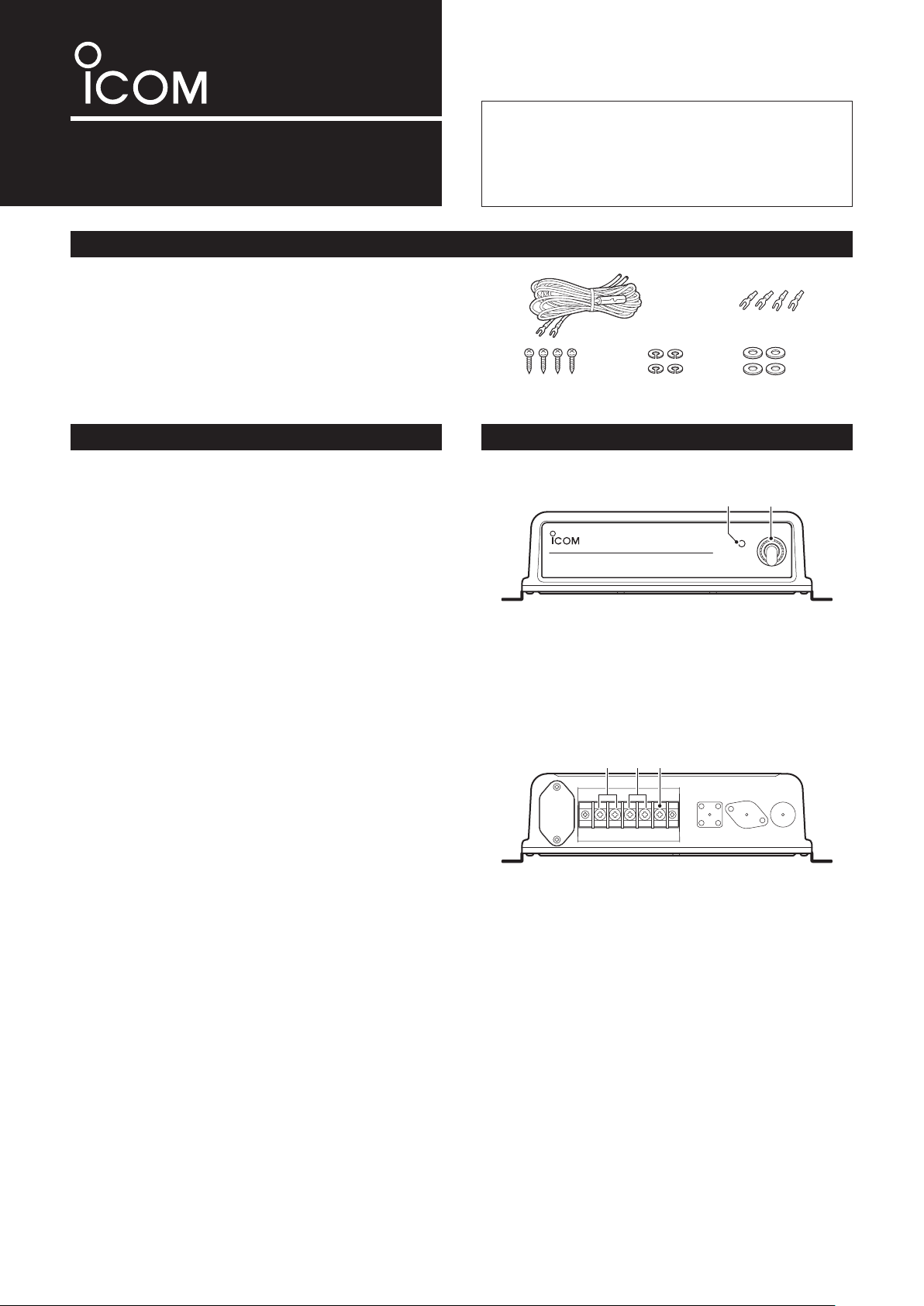
PANEL DESCRIPTIONS
• Front Panel
q POWER INDICATOR
Lights green during the power supply is turned ON.
w POWER SWITCH
Toggles to turn the power supply ON or OFF.
• Rear Panel
q DC POWER INPUT TERMINALS
Connect the 12 V/24 V storage batter y or 10.8 V to
31.2 V DC power supply through the supplied DC
power cable.
w DC POWER OUTPUT TERMINALS
Connect to the IC-GM651 through the DC power cable
supplied with IC-GM651.
e GROUND TERMINAL
Connects this terminal to ground to prevent electrical
shocks.
Page 2
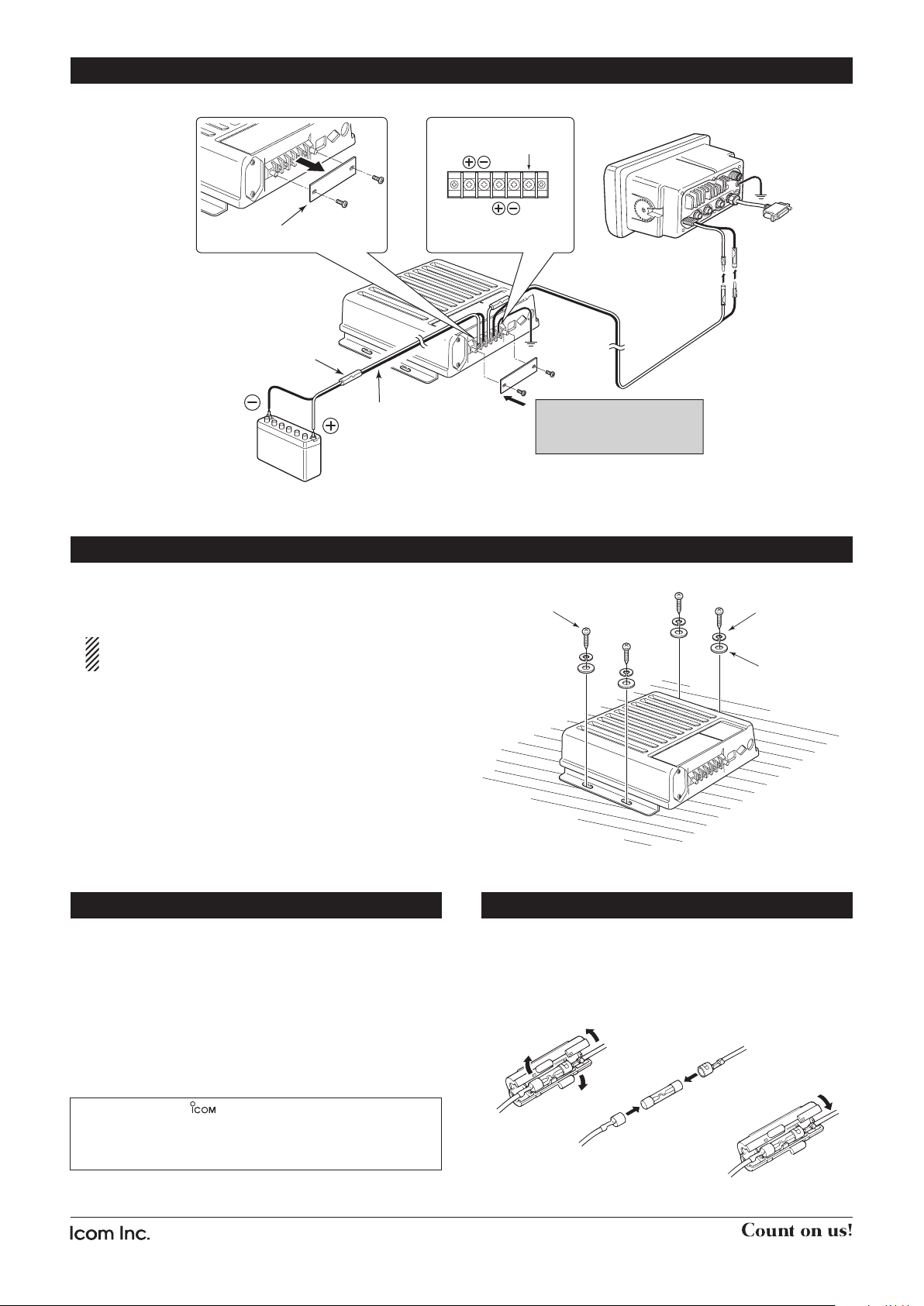
12 V/24 V battery
or PS-240
PS-250
IC-GM651
KEEP the terminal guard
attached after connecting
cables.
Supplied with
IC-GM651
Supplied with
PS-250
Fuse rating: 15 A
GND
Terminal guard
Detach the terminal guard first.
DC IN
12V/24V
DC OUT
12.5V
CONNECTIONS
Flat washer
Spring washer
Self-tapping
screw
Fuse rating: 15 A
• Mount the power supply securely with the four supplied
screws (M5×20 mm) to a surface which is more than 10
mm thick and can support more than 5 kg.
• DC input voltage : 10.8 V to 31.2 V DC
• Output voltage : 12.5 V DC
• Maximum output current : 5.3 A (nominal)
• Usable temperature range : –15°C to +55°C
• Dimensions : 250(W)×67(H)×200(D) mm
(projections not included)
• Weight (approx.) : 2.1 kg
Icom, Icom Inc. and the logo are registered trademarks of Icom Incorporate d (Japan) in the U nit ed St ate s, the U nit ed Ki ngd om, G ermany,
France, Spain, Russia and/or other countries.
All other products or brands are registered trademarks or trademarks of their
respective holders.
INSTALLATION
CAUTION: KEEP the power supply at least 1 meter
away from your vessel’s magnetic navigation compass.
SPECIFICATIONS
FUSE REPLACEMENT
One fuse is installed in the supplied DC power cable. If a
fuse blows or the power supply stops functioning, track
down the source of the problem, if possible, and replace
the damaged fuse with a new, rated one.
1-1-32 Kamiminami, Hirano-ku, Osaka 547-0003, Japan
A-6654H-1EX Printed in Japan
© 2008 Icom Inc.
 Loading...