

Icom id- rp2000v Instruction Manual

VHF DIGITAL VOICE REPEATER
id- rp2000v
Instruction Manual
This device complies with Part 15 of the FCC rules. Operation
is subject to the following two conditions: (1) This device may
not cause harmful interference, and (2) this device must accept
any interference received, including interference that may cause
undesired operation.

IMPORTANT
EXPLICIT DEFINITIONS
READ THIS INSTRUCTION MANUAL
CAREFULLY before attempting to operate the re-
peater.
SAVE THIS INSTRUCTION MANUAL. This
manual contains important safety and operating instructions for the ID-RP2000V.
Refer to the ID-RP2 instruction manual, supplied
with the ID-RP2C, about the Digital Smart Technologies for Amateur Radio (D-STAR) system repeater
instruction, installation and precautions, etc. for details.
Because this instruction manual describes IDRP2000V’s particular installation and precautions only.
PRECAUTIONS
R WARNING RF EXPOSURE! This device emits
Radio Frequency (RF) energy. Extreme caution should
be observed when operating this device. If you have
any questions regarding RF exposure and safety
standards, please refer to the Federal Communications Commission Office of Engineering and Technology’s report on Evaluating Compliance with FCC
Guidelines for Human Radio Frequency Electromagnetic Fields (OET Bulletin 65).
R WARNING HIGH VOLTAGE! NEVER attach an
antenna or internal antenna connector during transmission. This may result in an electrical shock or burn.
WORD DEFINITION
R WARNING
CAUTION Equipment damage may occur.
NOTE
R NEVER expose the ID-RP2000V to rain, snow or
any liquids. These units have no water protection.
AVOID using or placing the ID-RP2000V in areas with
temperatures below –10°C (+14°F) or above +50°C
(+122°F). Be aware that temperatures can exceed 80°C
(+176°F), resulting in permanent damage to the repeater if left there for extended periods.
AVOID placing the ID-RP2000V in excessively dusty
environments or in direct sunlight.
Place the repeater in a secure place to avoid inadvertent use by children.
Personal injury, fi re hazard or electric
shock may occur.
If disregarded, inconvenience only.
No risk or personal injury, fi re or electric shock.
R WARNING HIGH VOLTAGE! NEVER install
the antenna at any place that person touch the antenna easily during transmission. This may result in
an electrical shock or burn.
R NEVER apply AC to the [DC 13.8V IN] connector.
This could cause a fi re or ruin the repeater.
R NEVER apply more than 16 V DC, such as a 24
V battery, to the [DC 13.8V IN] connector on the repeater. This could cause a fi re or ruin the repeater.
R NEVER let metal, wire or other objects touch any
internal part or connectors on the repeater. This may
result in an electric shock.
R NEVER operate or touch the ID-RP2000V with
wet hands. This may result in an electric shock or
damage to the repeater unit.
DO NOT use chemical agents such as benzine or
alcohol when cleaning, as they can damage the repeater’s surfaces.
DO NOT modify the repeater for any reason.
Use the specifi ed fuse only.
For the U.S.A. only
CAUTION: Changes or modifi cations to this repeater,
not expressly approved by Icom Inc., could void your
authority to operate this repeater under FCC regulations.
Icom, Icom Inc. and the
marks of Icom Incorporated (Japan) in the United States,
the United Kingdom, Germany, France, Spain, Russia and/
or other countries.
Microsoft, Windows and Windows Vista are either registered
trademarks or trademarks of Microsoft Corporation in the
United States and/or other countries.
All other products or brands are registered trademarks or
trademarks of their respective holders.
i
logo are registered trade-
FOR CLASS B UNINTENTIONAL RADIATORS
This equipment has been tested and found to comply with
the limits for a Class B digital device, pursuant to part 15
of the FCC Rules. These limits are designed to provide
reasonable protection against harmful interference in a
residential installation. This equipment generates, uses and
can radiate radio frequency energy and, if not installed and
used in accordance with the instructions, may cause harmful interference to radio communications. However, there is
no guarantee that interference will not occur in a particular
installation.
TABLE OF CONTENTS
IMPORTANT ....................................................................... i
EXPLICIT DEFINITIONS .................................................... i
PRECAUTIONS .................................................................. i
FOR CLASS B UNINTENTIONAL RADIATORS............... ii
TABLE OF CONTENTS .................................................... ii
SUPPLIED ACCESSORIES .............................................. ii
1 SYSTEM OUTLINE ...................................................... 1
2 PANEL DESCRIPTIONS .............................................. 2
■ Front panel ........................................................................... 2
■ Rear panel ............................................................................ 2
3 CONNECTIONS AND INSTALLATIONS ................. 3–5
■ Precautions .......................................................................... 3
D About coaxial cable .......................................................... 3
■ About the power supply ........................................................ 3
■ When install into system rack ............................................... 4
■ Rubber feet attachment ........................................................ 4
■ Grounding ............................................................................. 4
■ System connections ............................................................. 5
4 DRIVER INSTALLATIONS ..................................... 6–26
■ Microsoft® Windows® XP (Service Pack 2) ........................... 6
■ Microsoft® Windows® 2000 ................................................. 11
■ Microsoft® Windows® 98SE/Me .......................................... 15
■ Microsoft® Windows Vista™ ............................................... 18
If this equipment does cause harmful interference to radio
or television reception, which can be determined by turning the equipment off and on, the user is encouraged to try
to correct the interference by one or more of the following
measures:
• Reorient or relocate the receiving antenna.
• Increase the separation between the equipment and receiver.
• Connect the equipment into an outlet on a circuit different
from that to which the receiver is connected.
• Consult the dealer or an experienced radio/TV technician
for help.
■ COM port confi rmation ....................................................... 22
D Microsoft® Windows® XP/2000 ....................................... 22
D Microsoft® Windows® 98SE/Me ...................................... 23
D Microsoft® Windows Vista™ ........................................... 24
■ USB driver un-installation ................................................... 25
5 UTILITY INSTALLATION ..................................... 27–29
■ Installation .......................................................................... 27
■ Un-installation ..................................................................... 29
6 REPEATER SETTINGS .............................................. 30
■ Frequency setting for ID-RP2000V ..................................... 30
7 MAINTENANCE ......................................................... 31
■ Troubleshooting .................................................................. 31
■ About cleaning .................................................................... 31
■ Fuse replacement ............................................................... 31
8 SPECIFICATIONS AND SYSTEM UNITS .................. 32
■ Specifi cations ..................................................................... 32
■ System units ....................................................................... 32
9 ABOUT CE ................................................................. 33
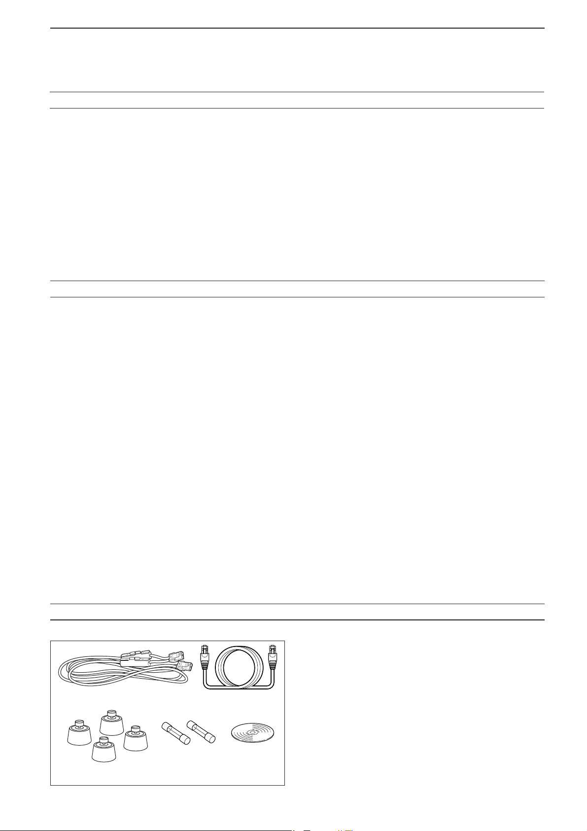
SUPPLIED ACCESSORIES
q
w
r
e
t
q Power cable (OPC- 1309; approx. 1 m; 3.3 ft) ........... 1
w Control cable (OPC-1069) ...................................... 1
e Rubber feet ........................................................... 4
r Spare fuses (FGB10A) ........................................... 2
t CD ........................................................................ 1
ii
1
Internet
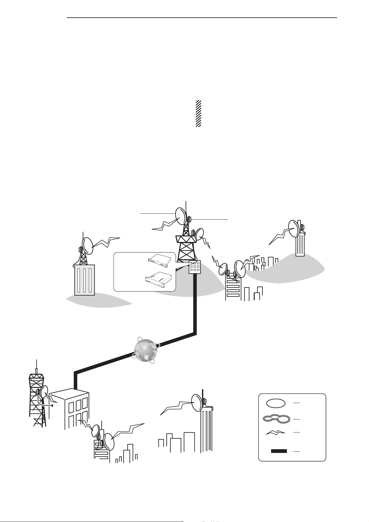
SYSTEM OUTLINE
The ID-RP2000V is installed into the D-STAR repeater system for operation.
The ID-RP2000V never functions as a repeater without the ID-RP2C because it has no relay function.
Antenna
■ ID-RP2000V
The ID-RP2000V is a 144 MHz digital voice and
slow-speed data repeater (4.8 kbps), and connects
to the ID-RP2C.
NOTE: No audio CODEC is performed in the ID-
RP2000V, and thus the ID-RP2000V receives and transmits 4.8 kbps serial data
only.
Different frequencies are used for each transmis-
sion and reception in semi-duplex mode.
The ID-RP2000V utility software, supplied with the
ID-RP2000V, and a PC are required for both receive and transmit frequency settings.
ID-RP2L*
ID-RP2C
ID-RP2000V
P
O
W
E
R
1
0
B
E
S
E
T
S
E
R
V
I
C
E
1
S
E
P
OW
ER
S
E
R
V
IC
E
T
S
E
R
V
IC
E
R
Internet
Internet
R
V
I
C
E
2
A
S
SIS
T
1
A
S
S
IS
T
2
R
e
I
p
D
e
-
a
t
R
e
P
r
C
2
o
V
n
t
r
o
l
l
e
r
*The ID-RP2L is not available
in European countries as of
May 2008.
Area
Zone
Signal
Internet
1
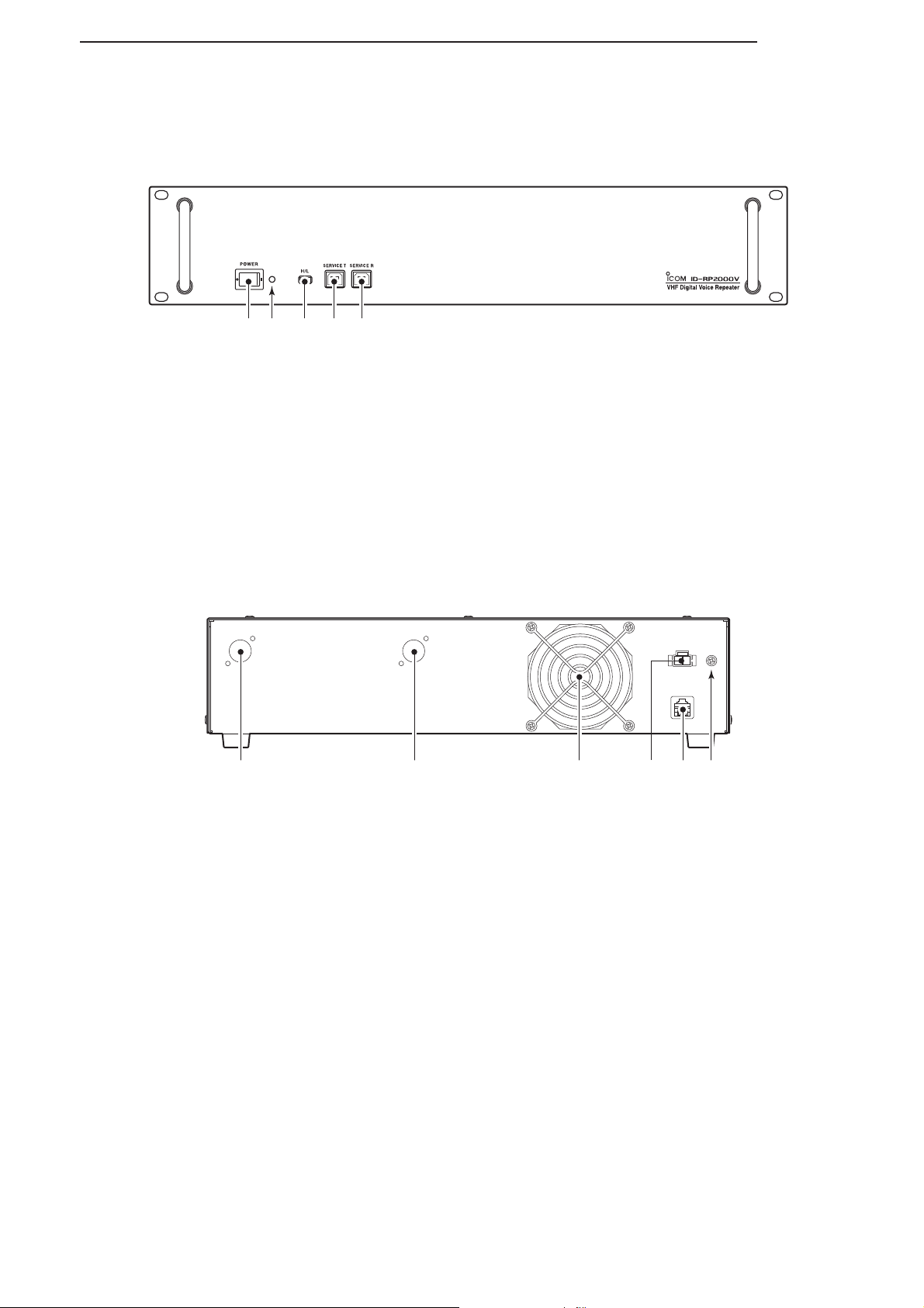
■ Front panel
qerw t
PANEL DESCRIPTIONS
2
q POWER SWITCH [POWER]
The power switch for the ID-RP2000V.
w POWER INDICATOR
The LED indicator for the ID-RP2000V, and lights
when the power is turned ON.
e HIGH/LOW POWER SELECT SWITCH [H/L]
Selects the transmit output power High (approx.
25 W)
and Low (approx. 2.5 W).
■ Rear panel
werq t y
q RECEIVE ANTENNA CONNECTOR [RX ANT]
(p. 5)
Connect a 144 MHz band antenna through a duplexer.
r SERVICE CONNECTOR T [SERVICE T] (p. 30)
Connects a PC via a USB cable (A-B type; purchase
separately)
t SERVICE CONNECTOR R [SERVICE R] (p. 30)
Connects a PC via a USB cable (A-B type; purchase
separately)
t [CONT I/O] (p. 5)
Connect to the ID-RP2C via the supplied control
cable for received or transmitted serial data communication.
to set the transmit frequency.
to set the receive frequency.
w TRANSMIT ANTENNA CONNECTOR [TX ANT]
(p. 5)
Connect a 144 MHz band antenna through a duplexer.
e COOLING FAN
r POWER CONNECTOR [DC13.8V] (p. 5)
Connect to the ID-RP2C via the supplied DC power
cable (OPC-1309) to be supplied the DC
power.
y GROUND TERMINAL [GND] (p. 4)
Connect to a ground to prevent electrical shocks,
TVI, BCI and other problems.
2
3
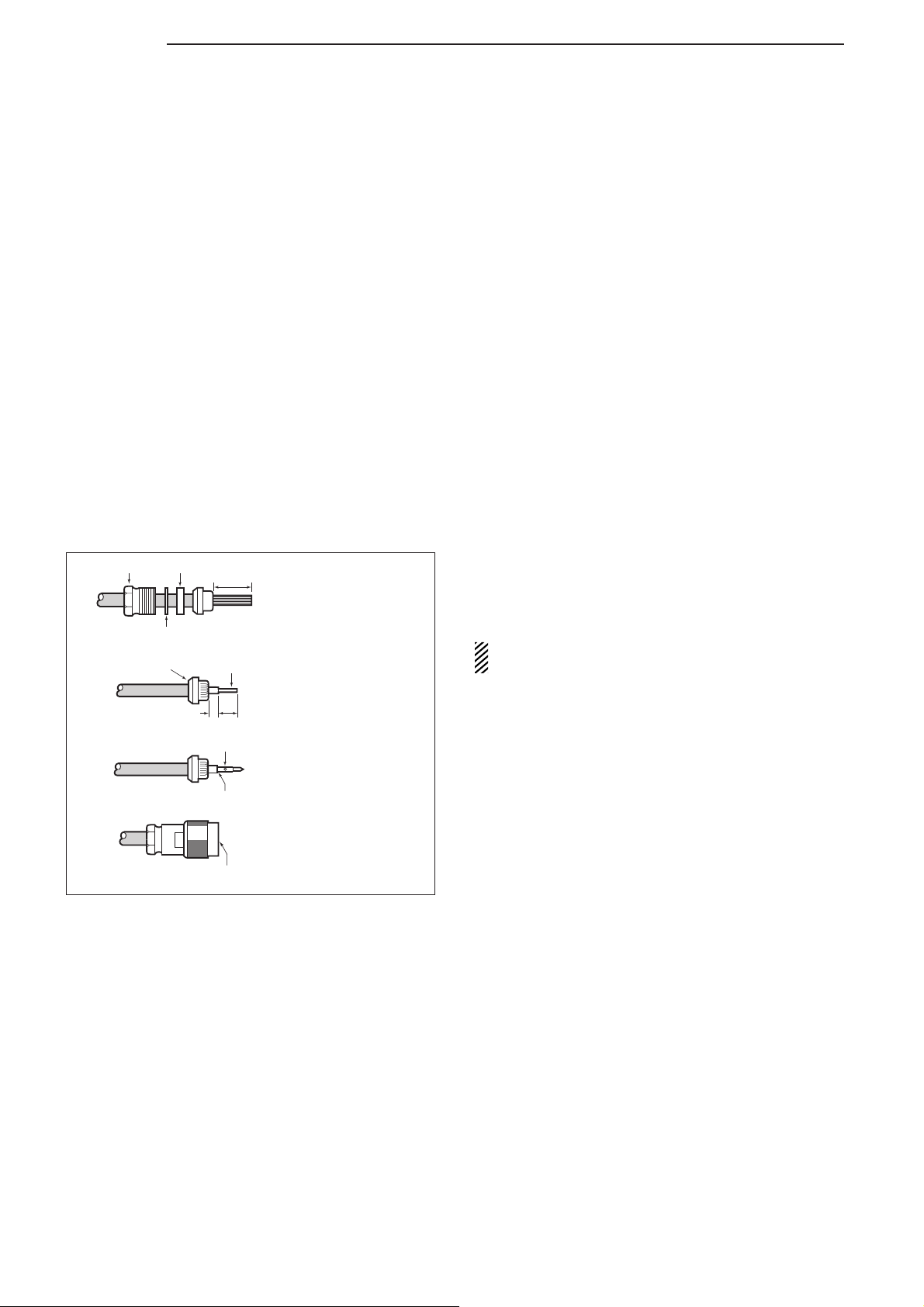
Slide the nut, washer,
rubber gasket and clamp
over the coaxial cable, then
cut the end of the cable
evenly.
Strip the cable and fold the
braid back over the clamp.
Soft solder the center
conductor. Install the
center conductor pin and
solder it.
Carefully slide the plug
body into the place aligning
the center conductor pin on
the cable. Tighten the nut
onto the plug body.
q
w
e
r
15 mm
3 mm
6 mm
No space
Solder hole
Be sure the center conductor is
the same height as the plug body.
Clamp
Center
conductor
Washer
Nut Rubber gasket
CONNECTIONS AND INSTALLATIONS
■ Precautions
NEVER expose the ID-RP2000V to rain, snow or any
liquids.
NEVER connect the repeater to a power source using
reverse polarity. This will damage the repeater.
And turn the repeater power OFF when connecting a
power supply.
AVOID using or placing the ID-RP2000V in areas with
temperature below –10˚C (+14˚F) or above +50˚C
(+122˚F).
AVOID placing the ID-RP2000V in excessively dusty
environments or in direct sunlight.
AVOID placing the ID-RP2000V against walls or putting anything on top of the units. This will obstruct
heat dissipation.
D About coaxial cable
• Type-N connector assembling
Use 50 Ω of impedance for both antenna (at Feeding
power point)
and coaxial cable.
■ About the power supply
Type-N connector is used for the connection between
the ID-RP2000V and antenna.
RECOMMENDATION: Install a surge protector
between the ID-RP2000V and antenna.
Make sure that the DC power supply that is used with
the ID-RP2000V system meets the followings:
Output voltage : 13.8 V DC ±15%
Current capacity : At least the total current consump-
tion of the connected equipment.
3

■ When install into system rack
■ Rubber feet attachment
CONNECTIONS AND INSTALLATIONS
The ID-RP2000V is designed to install into the
19-inch rack (EIA standard) directly.
Use the supplied bolts with the rack when fixing the
ID-RP2000V.
We recommend to use the rack that has rails because the weight of the ID-RP2000V is approx. 7.5 kg
(16.5 lbs).
3
q • Cross section
w
■ Grounding
Attach the supplied rubber feet onto the bottom of the
ID-RP2000V as shown at left when you do not install
the ID-RP2000V in the 19-inch rack. Desktop operation can be performed.
To prevent electrical shock, television interference
(TVI), broadcast interference (BCI) and other prob-
lems, ground the transceiver through the GROUND
terminal on the rear panel.
For the best results, connect a heavy gauge wire or
strap to a long earth-sunk copper rod.
Make the distance between the [GND] terminal and
ground as short as possible.
R WARNING: NEVER connect the [GND] ter-
minal to a gas or electric pipe, since the connection could cause an explosion or electric shock.
4
3
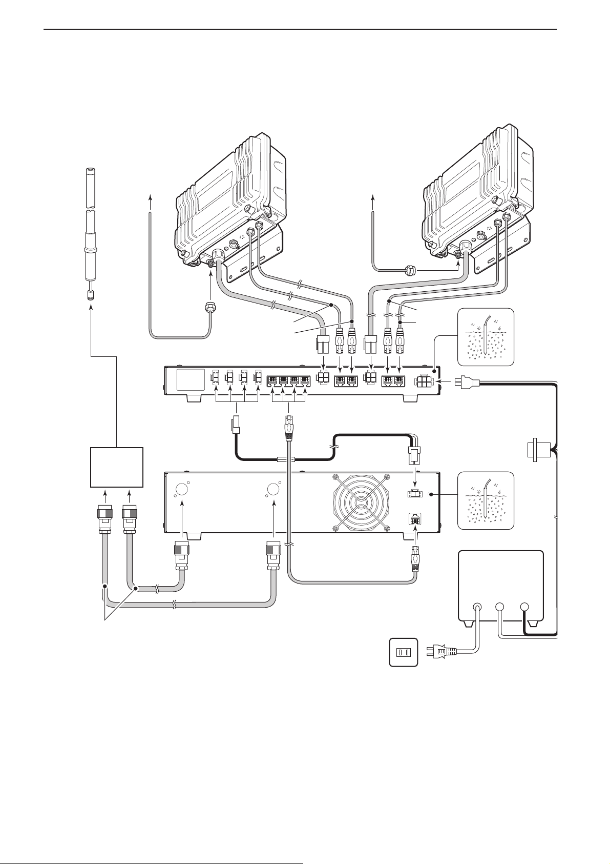
Duplexer
(purchase
separately)
ID-RP2000V
ID-RP2C
[A]
[B]
[B]
[A]
OPC-1380
(supplied w/ID-RP2C)
to AH-106/107*to AH-106/107*
OPC-1309
(supplied w/ID-RP2000V)
Control cable
(supplied w/ID-RP2000V)
ID-RP2L*
(Assist 1)
144 MHz band
antenna
(purchase separately)
ID-RP2L*
(Assist 2)
AC outlet
AC power cable
External DC power
supply 13.8 V
Black
_
Red
+
Coaxial cables
(purchase separately)
*Not available in European
countries as of May 2008.
CONNECTIONS AND INSTALLATIONS
■ System connections
5
DRIVER INSTALLATIONS
Click
Select
The USB (Universal Serial Bus) cable (A-B type; purchase
separately)
RP2000V and a PC.
So, the USB driver installation is required for the PC.
In addition, individual USB driver installation is required for each connector, because of the communication port number difference.
In this instruction, describes with the installation of the
ID-RP2000V [SERVICE T] connector for example.
NOTE:
The repeater unit connection may not be recognized with the PC according to the using USB cable
length.
Use the shorter USB cable as possible is recommended.
■ Microsoft® Windows® XP (Service Pack 2)
q Start up the Windows.
• Quit all applications if activated.
w Insert the CD supplied with the ID-RP2000V, into
the CD drive.
e Connect the PC and ID-RP2000V [SERVICE T]
connector using with a USB cable (A-B type; pur-
chase separately)
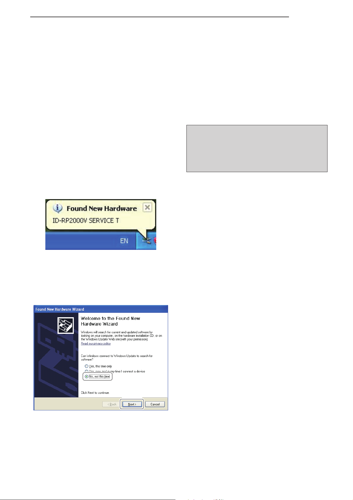
r “Found New Hardware ID-RP2000V SERVICE T”
appears as at left.
4
is used for the connection between the ID-
.
t The “Found New Hardware Wizard” will appear as
at left.
Select “No, not this time” and click [Next>].
☞ Continue to the next page.
6
4
DRIVER INSTALLATIONS
■ Microsoft® Windows® XP (Service Pack 2)— continued
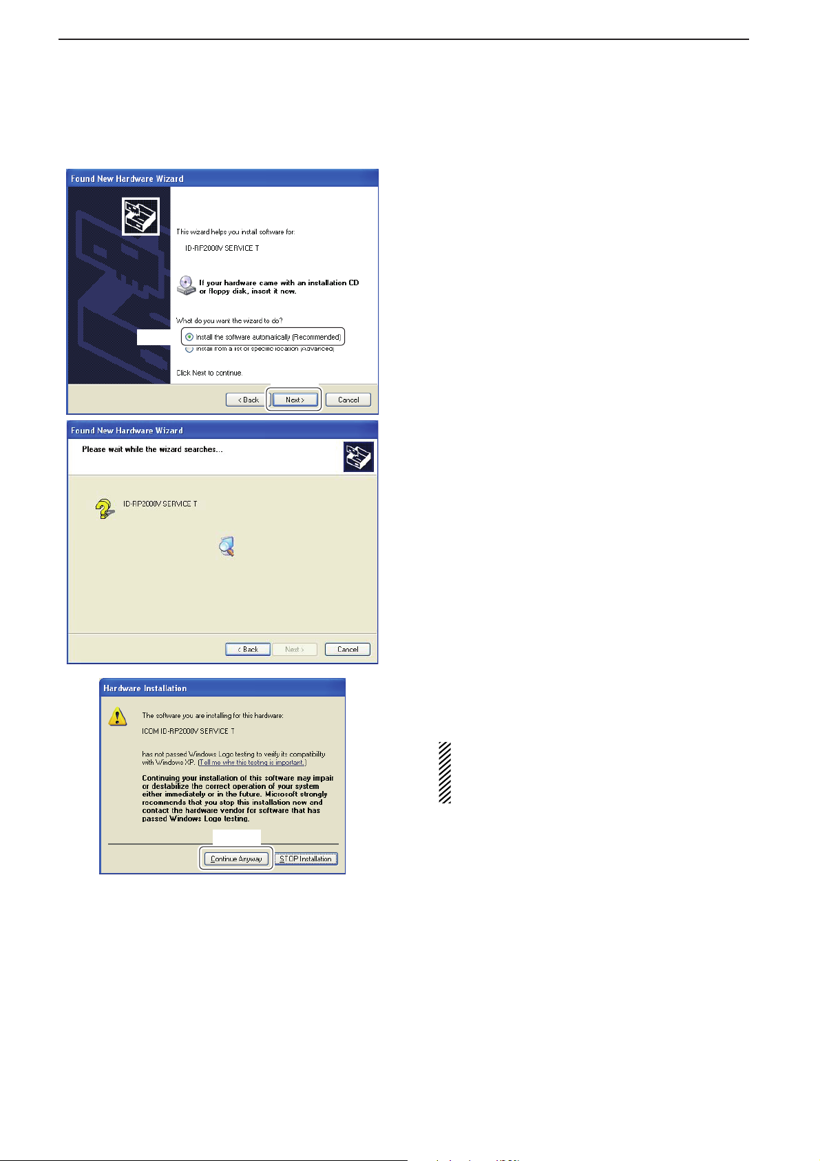
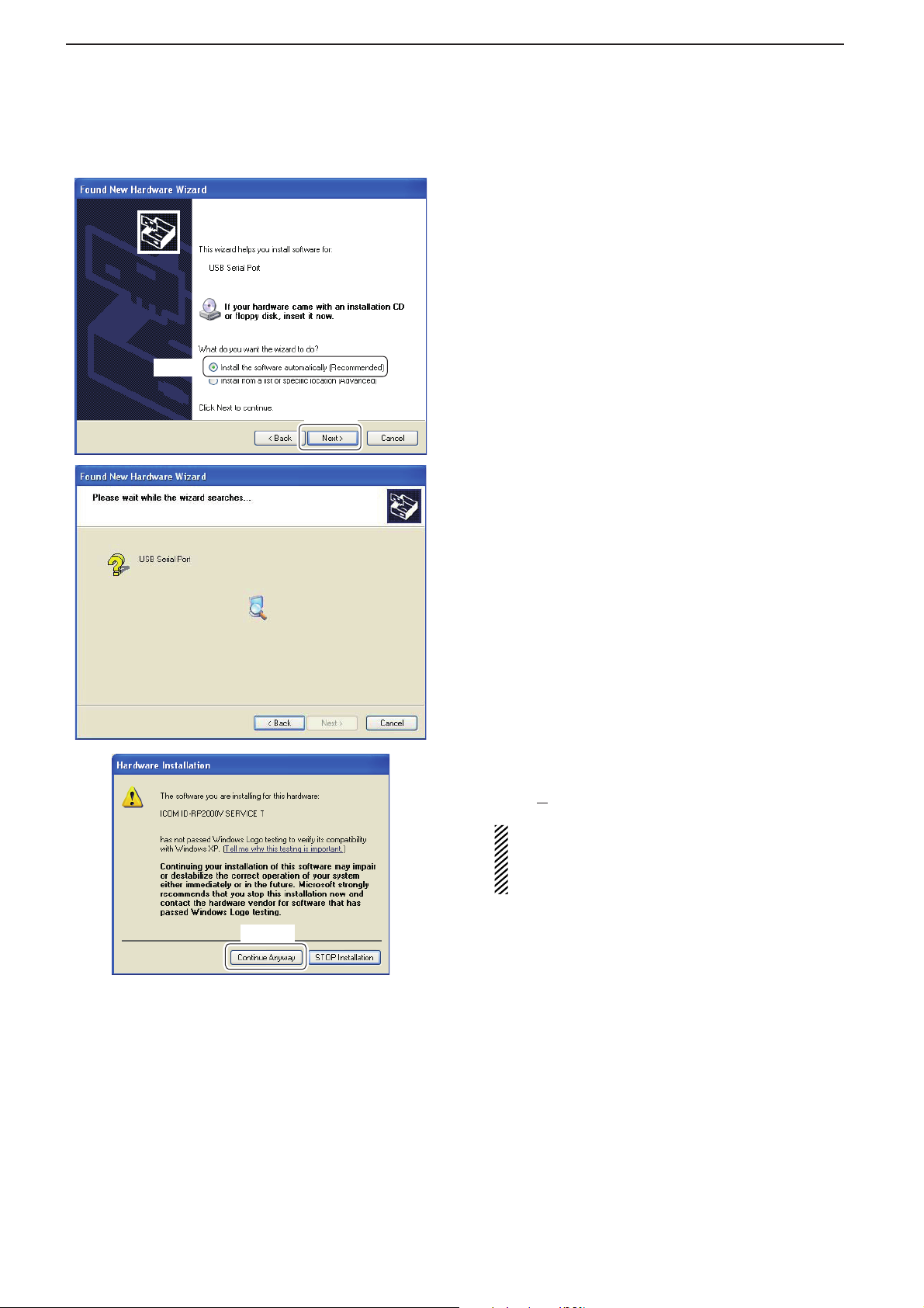
y When the dialog box as at left is displayed, select
“Install the software automatically (Recommended),” then click [Next>].
Select
Click
u The wizard starts searching for the driver and
shows the dialog as at left during search.
Click
i While searching the driver, the “Hardware Installa-
tion” dialog box appears as at left.
Click [Continue Anyway] to start the installation.
NOTE: If the dialog as at left does not appear,
select “Install from a list or specifi c location (Advanced)” in step y, then select the driver folder
in the CD.
7
DRIVER INSTALLATIONS
Click
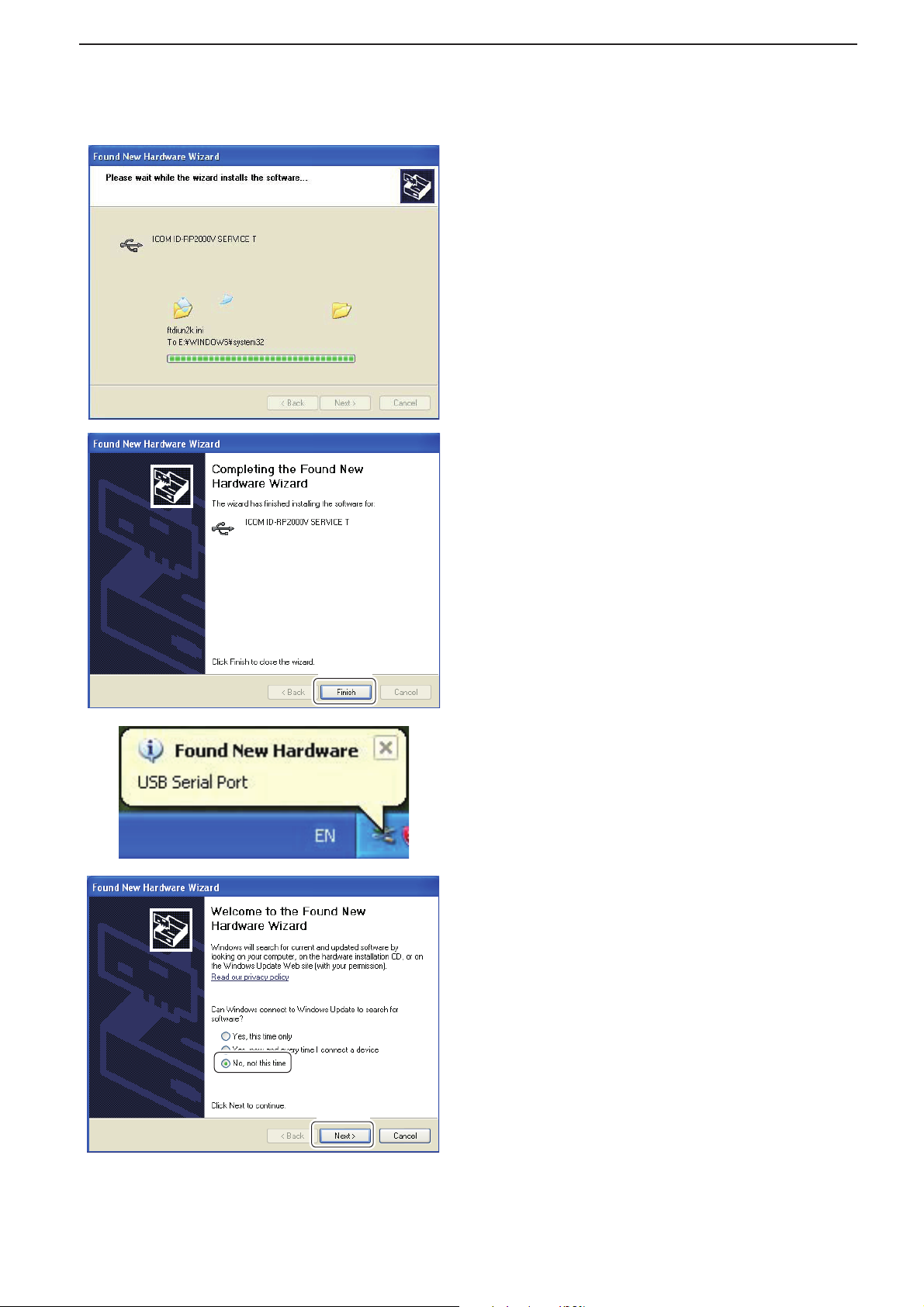
o Windows starts installing the USB driver.
!0 After the installation is completed, click [Finish].
4
Select
!1 After clicking [Finish], “Found New Hardware USB
Serial Port” appears as at left.
!2 The “Found New Hardware Wizard” will come up
as at left.
Select “No, not this time” then click [Next>].
Click
☞ Continue to the next page.
8
4
DRIVER INSTALLATIONS
■ Microsoft® Windows® XP (Service Pack 2)— continued
!3 Select “Install the software automatically (Recom-
mended),” then click [Next>].
Select
Click
!4 The wizard starts searching for the driver and
shows the dialog as at left during search.
Click
!5 While searching the driver, the “Hardware Installa-
tion” dialog box appears as at left.
Click [Continue Anyway] to start the installation.
NOTE: If the dialog as at left does not appear,
select “Install from a list or specifi c location (Advanced)” in step !3, then select the driver folder
in the CD.
9
 Loading...