

Icom ID-4100A, ID-4100E Advanced Manual

ADVANCED MANUAL
DUAL BAND TRANSCEIVER
ID-4100A
ID-4100E
INTRODUCTION
1 MEMORY OPERATION
2 SCAN OPERATION
3 PRIORITY WATCH
4 D-STAR OPERATION
5 GPS OPERATION
6 USING A microSD CARD
7 VOICE MEMORY
8 REPEATER AND DUPLEX OPERATIONS
9 MENU SCREEN
10 OTHER FUNCTIONS
This manual describes instructions for advanced features and
instructions.
See the Basic manual and the D-STAR guide that come with the
transceiver for precautions, installations, and basic operations.
11 OPTIONS
12 Bluetooth® OPERATION
13 UPDATING THE FIRMWARE
INDEX

INTRODUCTION
Previous view
Thank you for choosing this Icom product. This product is designed and built with Icom’ s state of the art technology
and craftsmanship. With proper care, this product should provide you with years of trouble-free operation.
This product combines traditional analog technologies with the new digital technology, Digital Smart Technologies for
Amateur Radio (D-STAR), for a balanced package.
ABOUT THE CONSTRUCTION OF THE MANUAL (As of April 2017)
You can use the following manuals to understand and operate this transceiver.
L If necessary, you can download a glossary of HAM radio terms from the Icom website.
Basic manual (Comes with the transceiver)
Instructions for the basic operations, precautions,
installation, and connections.
D-STAR Guide (Comes with the transceiver)
Instructions for registering your call sign on a gateway
repeater, and the basic operations of D-STAR.
About the DV Gateway function (PDF type)
Instructions on the system requirements or operations
needed to use the DV Gateway function.
L The guide “About the DV Gateway function” can be
downloaded from the Icom website.
Advanced manual (This manual)
Instructions for advanced operations, as shown below.
• Memory operation <Advanced>*
• Scan operation <Advanced>*
• Priority watch operation
• D-STAR operation <Advanced>*
• GPS operation
• Using a microSD card
• Voice memory operation
• Repeater and duplex operations
• Menu screen <Advanced>*
• Other functions
• Options <Advanced>*
• Bluetooth operation
L This manual can be downloaded from the Icom
website.
*The basic instructions are described on the Basic manual.
Icom, Icom Inc. and the Icom logo are registered trademarks of Icom Incorporated (Japan) in Japan, the United States, the United Kingdom,
Germany, France, Spain, Russia, Australia, New Zealand, and/or other countries.
Adobe, Acrobat, and Reader are either registered trademarks or trademarks of Adobe Systems Incorporated in the United States and/or other
countries.
The Bluetooth word mark and logos are registered trademarks owned by the Bluetooth SIG, Inc. and any use of such marks by Icom Inc. is
under license. Other trademarks and trade names are those of their respective owners.
Android and the Android logo are trademarks of Google, Inc.
IOS is a trademark or registered trademark of Cisco in the U.S. and other countries and is used under license.
Apple, iPad, and iPhone are trademarks of Apple Inc., registered in the U.S. and other countries.
App Store is a service mark of Apple Inc.
The iPhone trademark is used under license from AiPhone Co., Ltd.
Galaxy and Galaxy S are registered trademarks of Samsung Electronics Co., Ltd.
Google, the Google Logo, Google Play, the Google Play logo,
All other products or brands are registered trademarks or trademarks of their respective holders.
i

INTRODUCTION
Previous view
TABLE OF CONTENTS BY TOPIC
Controller
Attaching/Installing .................... Basic manual (sec. 1)
Front panel ................................ Basic manual (sec. 2)
Display ....................................... Basic manual (sec. 2)
Power key .................................. Basic manual (sec. 3)
Microphone
Connecting ................................ Basic manual (sec. 1)
HM-207S ................................... Basic manual (sec. 2)
Main unit
Connecting to a DC power source
............................................ Basic manual (sec. 1)
Installing in a vehicle ................. Basic manual (sec. 1)
Installing an antenna ................. Basic manual (sec. 1)
Front/Rear panel........................ Basic manual (sec. 2)
Bluetooth
Installing the UT-137..................Basic manual (sec. 1)
Details of Bluetooth operation ...............................12-2
microSD card
Inserting/Removing.................... Basic manual (sec. 7)
Saving the setting data ............................................6-4
Saving with a different le name ..............................6-9
Loading the saved data les that are on a
microSD card ...........................................................6-5
Backing up the data saved on a microSD card
onto a PC.................................................................6-6
Importing or Exporting a CSV formatted le ............6-8
MENU screen/Quick Menu
Quick Menu window .................. Basic manual (sec. 7)
MENU screen ..........................................................9-2
Memory channels
Memory channels ....................................................1-2
Manage Memory screen description .......................1-3
Memory name display ...........................................1-12
Scan
Scan operation
Setting and clearing a Skip channel
Priority Scan operation
........................................................2-2
........................2-8
............................................3-2
GPS
GPS operation .........................................................5-2
Checking your GPS position....................................5-3
Checking GPS information (Sky view screen) ....... 5-11
Transmitting D-PRS data ............................. 5-12, 5-13
Transmitting NMEA data .............................. 5-12, 5-25
GPS Logger function .............................................5-34
GPS Auto transmission..........................................5-38
D-STAR
Register your call sign on a
gateway repeater
“FROM” (Access repeater) setting...........................4-3
“TO” (Destination) setting ........................................4-8
Connecting to a Reector ......................................4-13
Message operation ................................................4-17
Viewing the received call signs ..............................4-19
BK mode communication.......................................4-21
EMR communication .............................................4-22
Automatic DV detection .........................................4-23
Automatic Reply function .......................................4-24
Data communication ..............................................4-27
Digital call sign squelch/
Digital code squelch functions ...............................4-29
Viewing call signs ..................................................4-31
Repeater list ..........................................................4-32
Adding Repeater information
using the RX History ..............................................4-39
Skip setting for a DR scan .....................................4-40
Entering a repeater group name............................4-41
Repeater detail screen ..........................................4-42
Entering Your (destination) call sign ......................4-43
REPEATER AND DUPLEX OPERATIONS
Duplex operation .....................................................8-4
Auto repeater function .............................................8-5
Off band indication ...................................................8-5
VOICE MEMORY
Recording a QSO audio ..........................................7-2
Playing back the recorded audio .............................7-3
Changing the QSO recorder settings ......................7-4
Deleting the audio folder/le ....................................7-5
Viewing the le information ......................................7-6
Viewing the microSD card memory capacity ...........7-7
Playing back the recorded audio on the PC ............7-8
...................................D-STAR Guide
ii
INTRODUCTION
Previous view
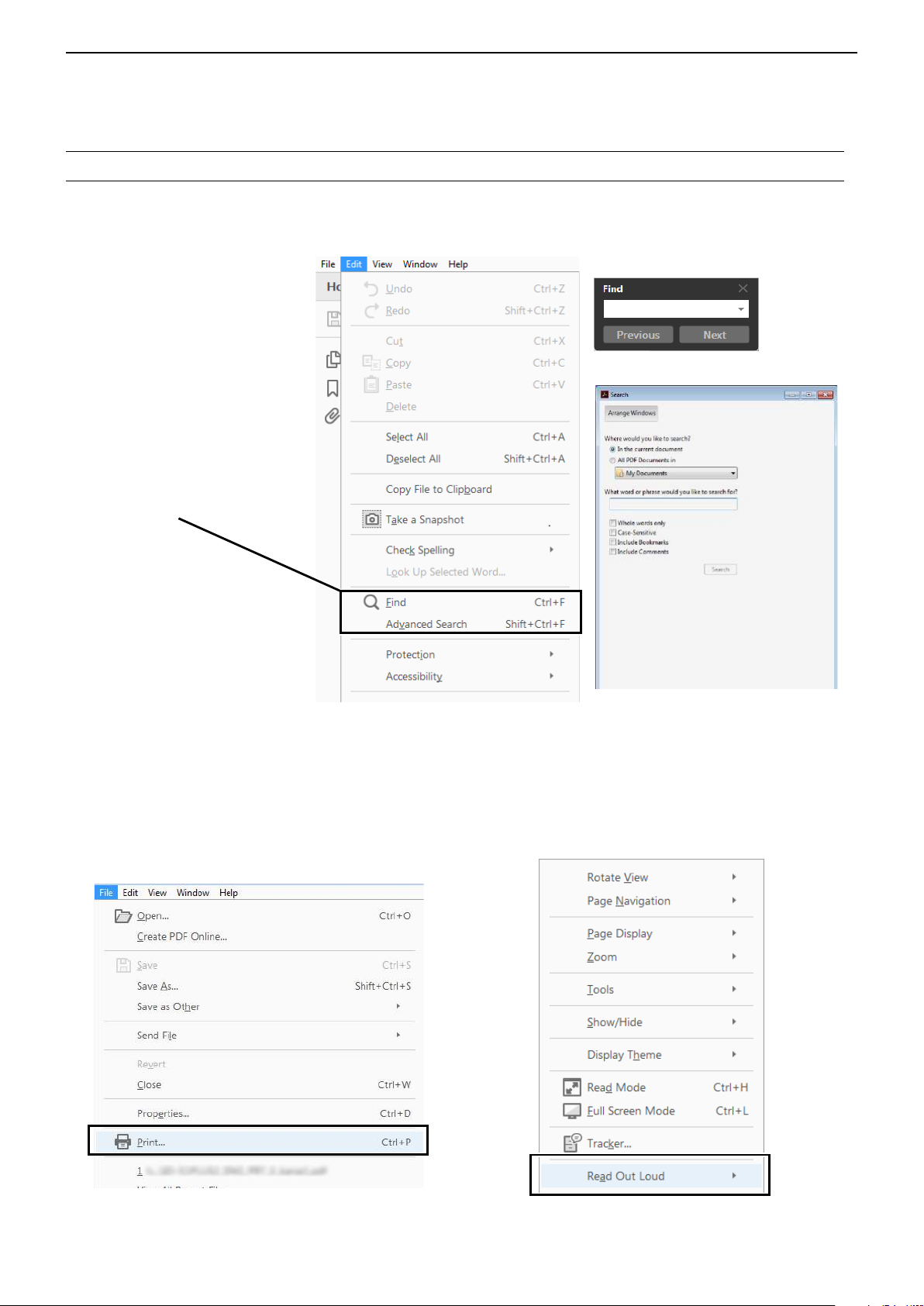
Functions and features of Adobe® Acrobat® Reader
The following functions and features can be used with Adobe® Acrobat® Reader®.
• Keyword search
Click “Find” (Ctrl+F) or “Advanced
Search” (Shift+Ctrl+F) in the Edit
menu to open the search screen.
This is convenient when search-
ing for a particular word or phrase
in this manual.
* The menu screen may differ,
depending on the Adobe
Reader® version.
®
Acrobat
®
Click to open the find or search
screen or advanced search screen.
• Find screen
• Advanced search screen
®
• Printing out the desired pages.
Click “Print” in the File menu, and then select the
paper size and page numbers you want to print.
* The printing setup may differ, depending on the
printer. Refer to your printer’s instruction manual
for details.
* Select "A4" size to print out the page in the original
manual size.
• Read Out Loud feature.
The Read Out Loud feature reads aloud the text in
this PDF.
Refer to the Adobe
®
Acrobat® Reader® Help for the
details.
( This feature may not be usable, depending on your
PC environment including the operating system.)
* The screen may differ, depending on the Adobe® Acrobat® Reader®
version.
iii
INTRODUCTION
Previous view
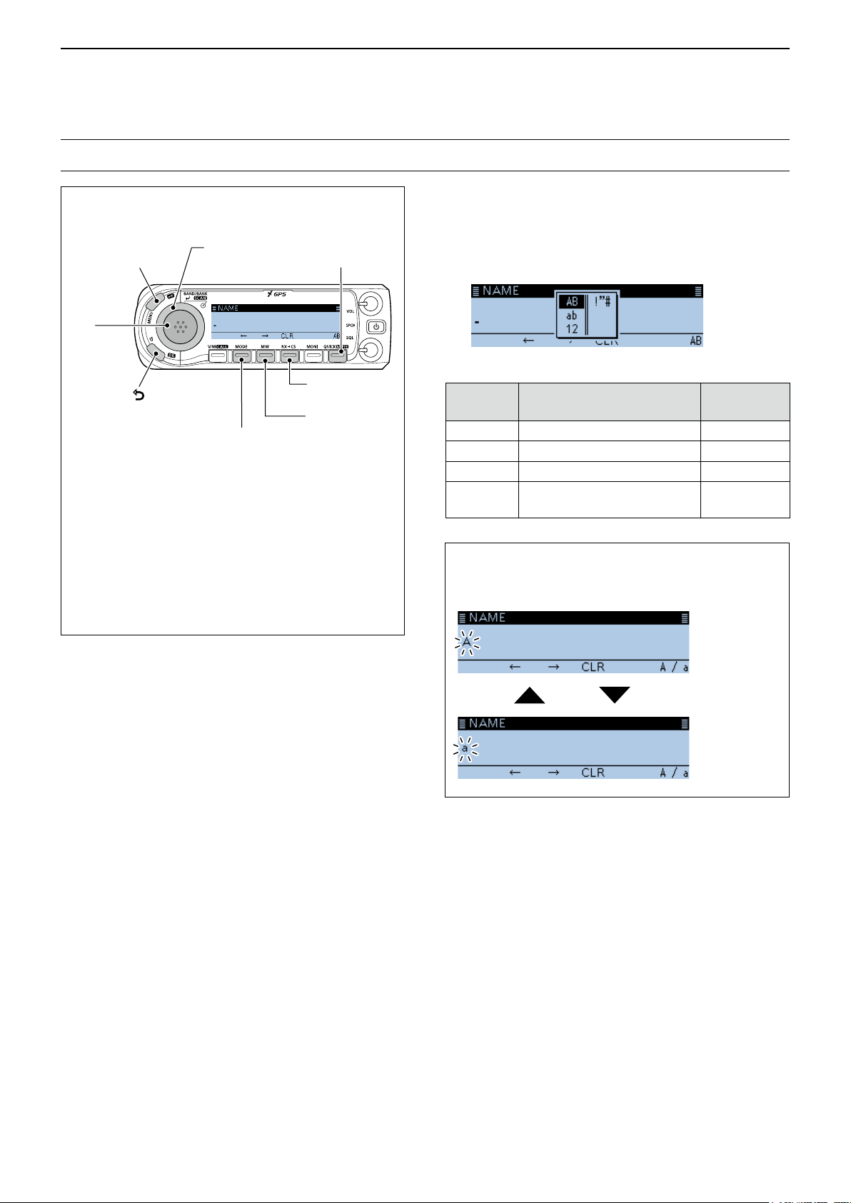
Entering and editing text
Controls used for text entry
[QUICK]
[MENU]
Cancels
[DIAL] (Rotate)
Selects
Selects the
character type
[ï]
Sets
[]
Cancels
[MODE]
Moves the
cursor to the left
[RX→CS]
Clears
[MW]
Moves the
cursor to the
right
• To insert a text, move the cursor to a place to
enter, then rotate [DIAL].
• To clear a character, push [RX→CS].
• To consecutively clear characters, continuously
hold down [RX→CS].
• When the character type is “AB” or “ab,” and while
entering a character, push [QUICK] to convert
between upper case and lower case letters.
To change the character type
1. When not selecting text, or an entered text is
selected, push [QUICK].
2. Rotate [DIAL] to select the character type, then
push [ï].
Character
type
AB
ab
12
!”#
Selectable characters
and symbols
A to Z, (space)
a to z, (space)
0 to 9, (space)
! " # $ % & ’ ( ) * + , - . / : ; < =
> ? @ [ \ ] ^ _ ` { | } ˜ (space)
Character
conversion
A/a
A/a
–
–
TIP: When the character type is “AB” or “ab,” and
while entering a character, push [QUICK] to convert
between upper case and lower case letters.
Push
[QUICK]
iv
INTRODUCTION
Previous view
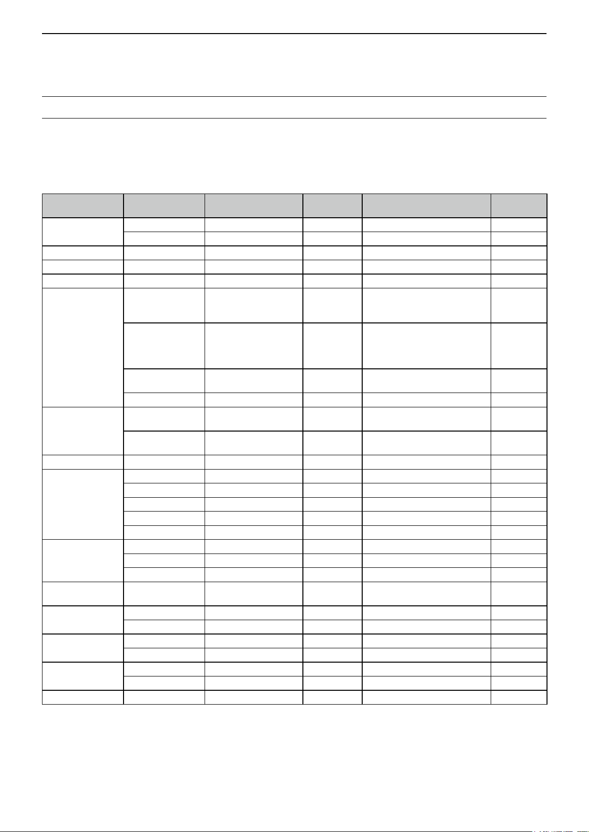
Entering and editing text (Continued)
DUsable characters
The usable characters and symbols, and the maximum characters differ, depending on the item.
See the following list for details.
L The usable characters and symbols for each character type are described at the bottom of the page.
Category Item Character type
Manage Memory
Program scan Scan name [AB] [ab] [12] [!”#] 16 – p. 2-9
P-LINK Scan Link name [AB] [ab] [12] [!”#] 16 – p. 9-20
My Station TX Message [AB] [ab] [12] [!”#] 20 – p. 4-17
GPS TX Mode
SD Card
Bluetooth Set Device name [AB] [ab] [12] [!”#] 8 Except for “ICOM BT-” p. 9-72
Repeater List
CS screen
My Call Sign Call sign A to Z, 0 to 9, /, space 12 (+1)
Your Call sign
GPS Memory
DR screen
DTMF Memory DTMF code 0 to 9, A, B, C, D, *, # 24 – p. 10-8
Memory name [AB] [ab] [12] [!”#] 16 – p. 1-10
Bank name [AB] [ab] [12] [!”#] 16 – p. 1-11
Unproto Address [AB] [ab] [12] [!”#] 56
Comment [AB] [ab] [12] [!”#] 43
Object Name
Item Name
GPS Message [AB] [ab] [12] [!”#] 20 – p. 5-26
Save Setting [AB] [ab] [12] [!”#] 20
Export [AB] [ab] [12] [!”#] 20
Group name [AB] [ab] [12] [!”#] 16 – p. 4-41
Repeater name [AB] [ab] [12] [!”#] 16 – p. 4-34
Sub name [AB] [ab] [12] [!”#] 8 – p. 4-34
Call sign A to Z, 0 to 9, /, space 8 – p. 4-34
GW Call sign A to Z, 0 to 9, /, space 8 – p. 4-34
UR A to Z, 0 to 9, /, space 8 – p. 9-41
R1 A to Z, 0 to 9, /, space 8 – p. 9-41
R2 A to Z, 0 to 9, /, space 8 – p. 9-41
Name [AB] [ab] [12] [!”#] 16 – p. 4-43
Call sign A to Z, 0 to 9, /, space 8 p. 4-43
Memory name [AB] [ab] [12] [!”#] 16 – p. 5-27
Group name [AB] [ab] [12] [!”#] 16 – p. 5-30
Direct Input (UR) A to Z, 0 to 9, /, space 8 – p. 4-11
Direct Input (RPT) A to Z, 0 to 9, /, space 8 – p. 4-12
[AB] [ab] [12] [!”#] 9 – p. 5-17
Maximum
characters
Information Reference
Normally 12 characters
(API410,DSTAR*)
The number of characters you
can enter differs, depending on
the data extension and altitude
settings.
Illegal characters:
/ : ; * < >
Illegal characters:
/ : ; * < >
Includes “/” between the Call
sign and Memo field.
p. 5-15
p. 5-17
p. 5-21
p. 5-16
p. 5-18
p. 5-22
p. 6-4
p. 6-9
p. 9-47
[AB]: A to Z, (space)
[ab]: a to z, (space)
[12]: 0 to 9, (space)
[!”#]: ! " # $ % & ’ ( ) * + , - . / : ; < = > ? @ [ \ ] ^ _ ` { | } ˜ (space)
v
INTRODUCTION
Previous view
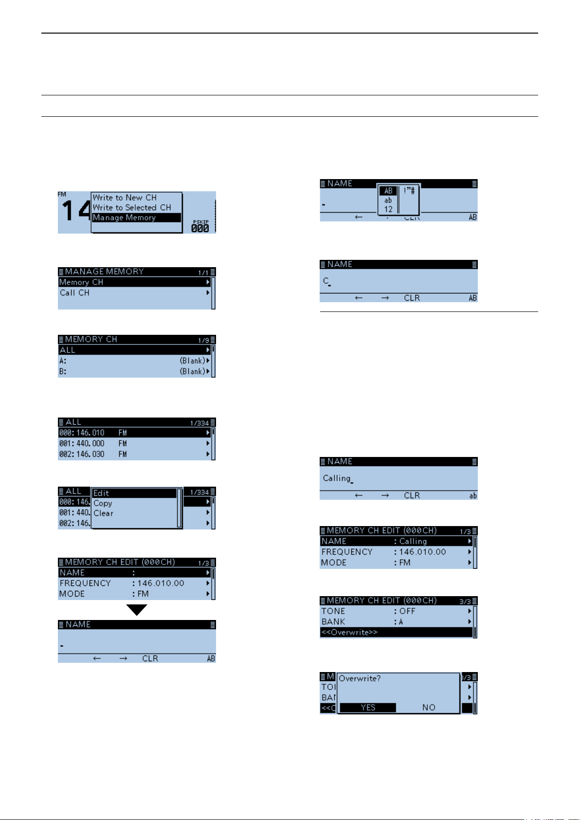
Entering and editing text (Continued)
DHow to enter
(Example: Entering “Calling” as a Memory name.)
1. Push [MW].
2. Rotate [DIAL] to select “Manage Memory,” then
push [ï].
8. Push [QUICK].
9. Select the character type, then push [ï].
• Displays the MANAGE MEMORY screen.
3. Select “Memory CH,” then push [ï].
4. Select “ALL,” then push [ï].
• Displays the ALL screen.
5. Rotate [DIAL] to select the Memory channel to
enter a name, then push [QUICK].
6. Select “Edit,” then push [ï].
10. Rotate [DIAL] to select a character, then push [ï].
(Example: C)
InformationL
• To move the cursor forward, push [MW].
• To move the cursor backward, push [MODE].
• To insert a text, move the cursor to a place to enter,
then rotate [DIAL].
• To clear a character, push [RX→CS].
• To consecutively clear characters, continuously hold
down [RX→CS].
• When the character type is “AB” or “ab,” and while
entering a character, push [QUICK] to convert
between upper case and lower case letters.
11. Repeat step 8 ~ 10 to enter a name.
(Example: Calling)
12. After entering, push [ï].
7. Select “NAME,” then push [ï].
• Enters the name entry mode.
13. Select “<<Overwrite>>,” then push [ï].
• The conrmation dialog “Overwrite?” is displayed.
14. Select <YES>, then push [ï].
• Beeps sound, and writes the entered name to the
channel.
vi

Section 1 MEMORY OPERATION
Previous view
General description ................................................................ 1-2
D The number of the Memory channel ............................... 1-2
D Memory channel content ................................................ 1-2
Manage Memory screen description ...................................... 1-3
D Tree view of the Manage Memory screen ....................... 1-3
D Displaying the Manage Memory screen ......................... 1-3
Selecting a Memory channel .................................................. 1-4
Selecting a Call channel ......................................................... 1-4
Writing to a Memory channel .................................................. 1-5
D Writing to the selected channel ....................................... 1-5
D Writing to a blank channel............................................... 1-5
D Overwriting to the selected channel ................................ 1-6
D Copying Memory content to the VFO ............................. 1-6
D Copying Memory content to another Memory channel ... 1-7
Memory bank setting .............................................................. 1-8
D Assigning a memory channel to a memory bank ............ 1-8
D Directly writing into a memory bank ................................ 1-9
D Selecting the Memory Bank mode .................................. 1-9
Entering a Memory or Bank name ....................................... 1-10
D Entering a Memory name ............................................. 1-10
D Entering a Bank name ...................................................1-11
Selecting a Memory name display........................................ 1-12
Clearing a Memory channel.................................................. 1-12
1-1

1
Previous view
MEMORY OPERATION
General description
The transceiver has a total of 1000 Memory channels
(100 channels in each of 26 memory banks, A ~ Z)
and two Call channels (C0/C1) each for the 144 and
430 MHz bands.
The Memory mode is useful to quickly select oftenused frequencies.
DThe number of the Memory channel
Memory Channels Descriptions
000 ~ 999 (Total of 1000) Regular Memory channels.
C0/C1
Two Call channels (C0/C1) each for the 144 and 430 MHz bands.
Instantly recalls a specied frequency.
DMemory channel content
The following information can be entered into the
Memory channels:
• Operating frequency
• Duplex direction (DUP+ or DUP–) and frequency
offset
• Memory name
• Scan skip setting
• Tuning step
• Operating mode
• Subaudible tone encoder, tone squelch or DTCS
squelch ON/OFF
• Subaudible tone frequency, tone squelch frequency
or DTCS code with polarity
• UR station call sign
• R1/R2 call signs
• Digital Call sign squelch or Digital code squelch ON/
OFF
• Digital code
• Memory bank
NOTE: Memory content may be accidentally
cleared by static electricity, electric transients,
and other causes. In addition, it may be cleared
by a malfunction, or during repairs. Therefore, we
recommend that you backup the memory content or
save it to a microSD card* or to a PC.
*User supplied
L The CS-4100 cloning software can also be used to
backup your memory data.
1-2
1
Previous view
MEMORY OPERATION
Manage Memory screen description
The MANAGE MEMORY screen enables you to easily
manage the Memory or Call channel content.
• Displays the Memory or Call channel content.
• Easy to assign to a bank, and displays the bank
content.
• Easy to add, edit, copy, or clear the Memory
channels.
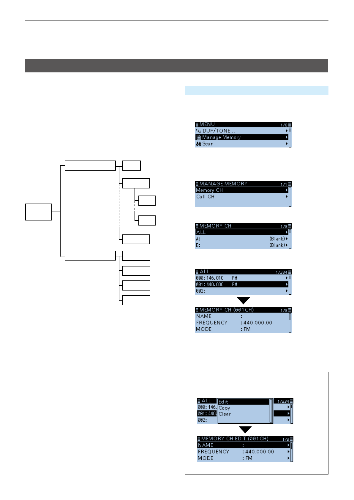
DTree view of the Manage Memory screen
Memory CH
Manage
Memory
ALL
Bank A
A00
A99
Bank Z
DDisplaying the Manage Memory screen
Manage Memory > Memory CH
1. Push [MENU].
2. Rotate [DIAL] to select “Manage Memory,” then
push [ï].
• Displays the MANAGE MEMORY screen.
L You can display the MANAGE MEMORY screen by
pushing [MW] on other than the DR screen.
3. Select “Memory CH,” then push [ï].
4. Select “ALL,” then push [ï].
Call CH
C0 144
C1 144
C0 430
C1 430
• Displays the ALL screen.
5. Select a channel, then push [ï].
• Displays the Memory content.
L Rotate [DIAL] to select the page.
6. Push [MENU].
• Returns to the standby screen.
TIP: To edit, copy or clear the memory content.
1. Push [QUICK] in step 5.
2. Select “Edit,” “Copy” or “Clear,” then push [ï].
(Example: When selecting “Edit.”)
1-3
1
Previous view
MEMORY OPERATION
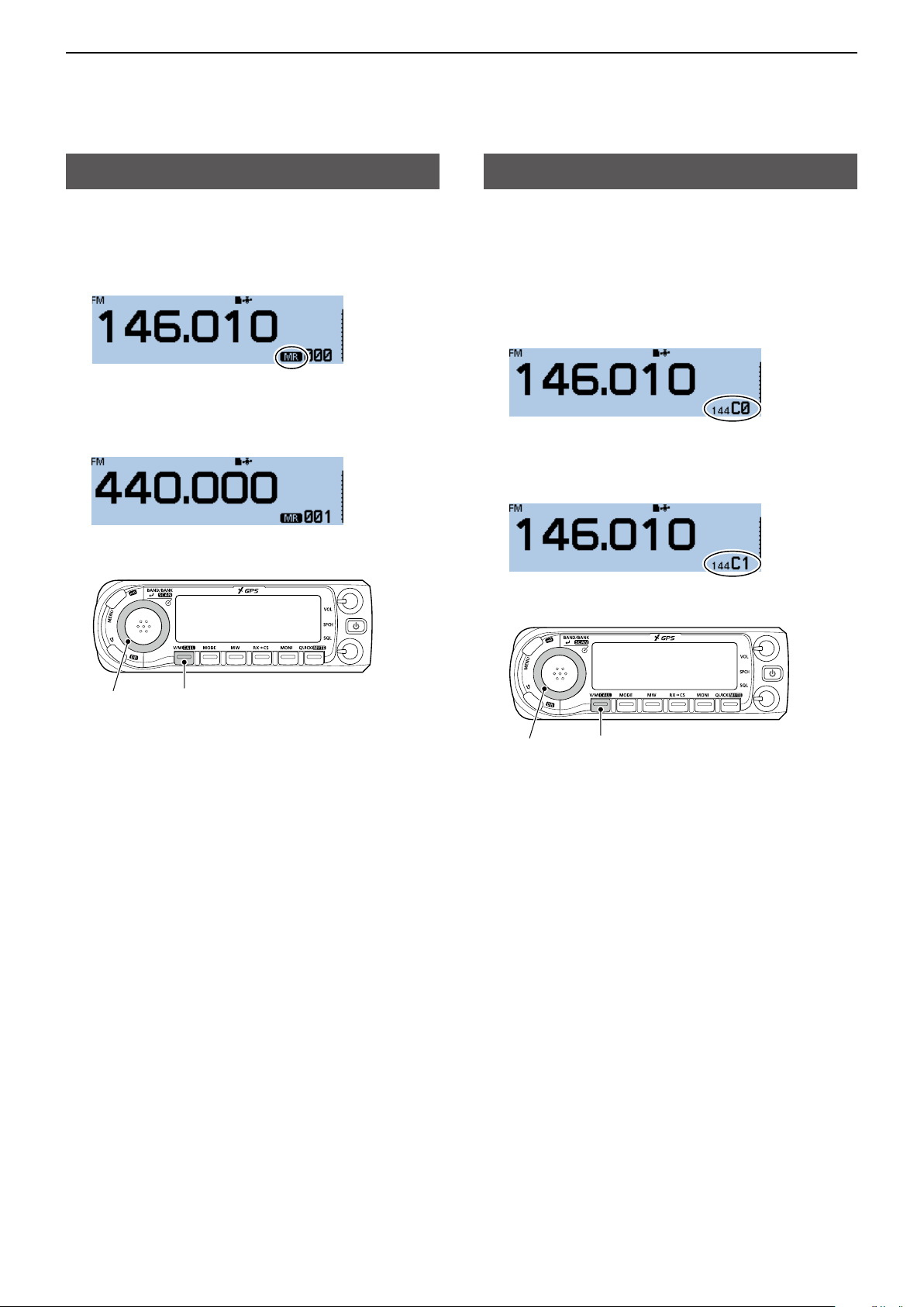
Selecting a Memory channel
In the Memory mode, you can select the Memory
channels by rotating [DIAL].
1. Push [V/M] several times until you enter the
Memory mode.
L Pushing [V/M] toggles between the VFO and Memory
modes.
2. Rotate [DIAL].
• Selects a Memory channel.
L Blank channels are not selectable.
Selecting a Call channel
Two Call channels (C0/C1) are selectable in each of
the 144 and 430 MHz bands.
Factory default frequencies and operating modes are
entered into the Call channels. Change these to suit
your operating needs.
1. Hold down [CALL] for 1 second.
• Enters the Call channel mode.
L Pushing [CALL] again cancels the Call channel
mode.
2. Rotate [DIAL].
• Selects a Call channel.
[DIAL]
[V/M]
[DIAL]
[CALL]
1-4
1
Previous view
MEMORY OPERATION
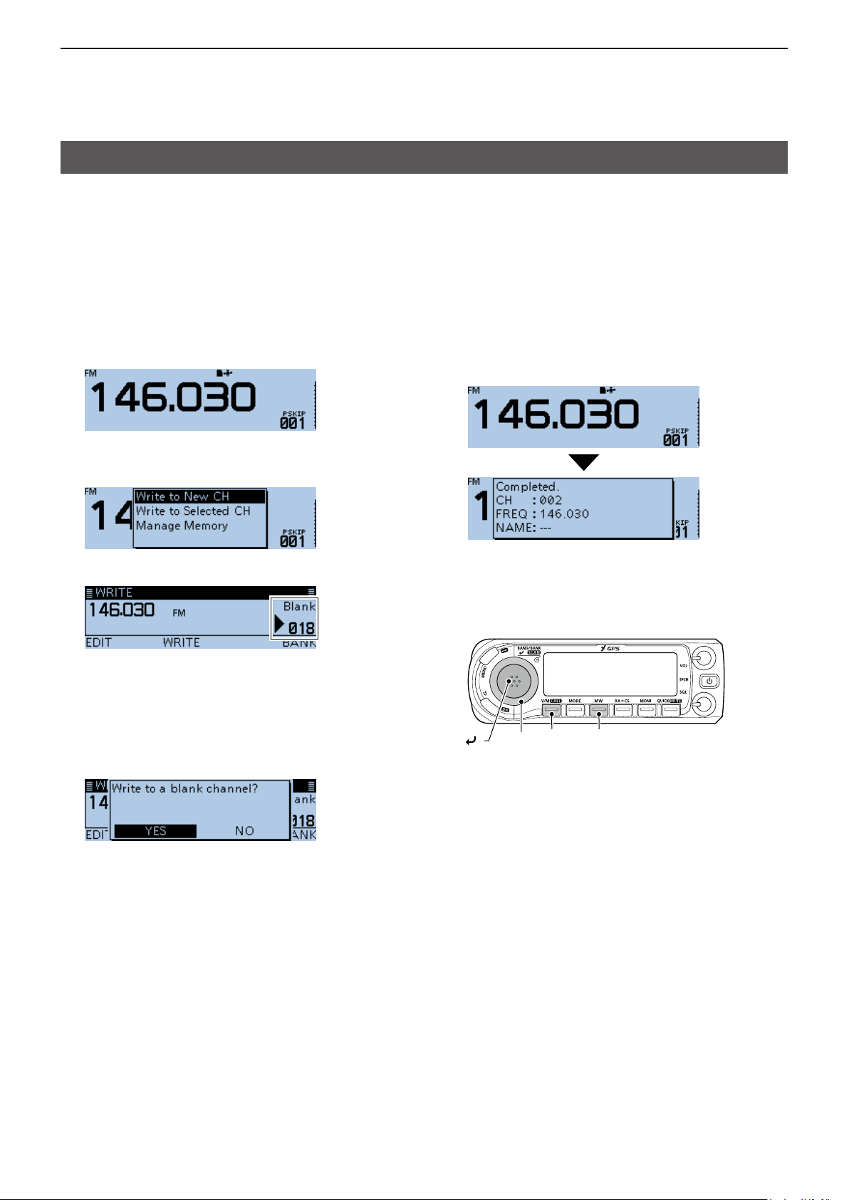
Writing to a Memory channel
After setting a frequency in the VFO mode, you can
write it to a selected channel or an automatically
selected blank channel.
Memory channels 002 to 999 are blank as the default.
DWriting to the selected channel
Example: Writing 146.030 MHz into Memory channel 18.
1. Push [V/M] several times until you enter the VFO
mode.
2. Rotate [DIAL] to select 146.030 MHz.
3. Push [MW].
4. Rotate [DIAL] to select “Write to New CH.”
5. Rotate [DIAL] to select the Memory channel “018.”
L If you select a pre-entered channel, the previous
channel content will be overwritten.
L The Call channels are also selectable.
6. Push [MW].
• The conrmation dialog “Write to a blank channel?” is
displayed.
7. Select <YES>, then push [ï].
DWriting to a blank channel
Example: Writing 146.030 MHz into a blank channel.
1. Push [V/M] several times until you enter the VFO
mode.
2. Rotate [DIAL] to set 146.030 MHz.
3. Hold down [MW] for 1 second.
• Beeps sound, and automatically writes into a blank
channel.
• Returns to the standby screen (VFO mode).
[V/M] [MW]
[DIAL]
[ ]
• Beeps sound, and writes into the selected Memory
channel.
• Returns to the standby screen (VFO mode).
1-5
1
Previous view
MEMORY OPERATION
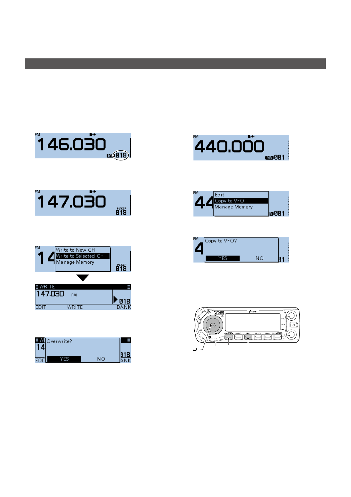
Writing to a Memory channel (Continued)
DOverwriting to the selected channel
You can write a frequency into a pre-entered channel.
Example: Writing 147.030 MHz into Memory channel
“018.”
1. Push [V/M] several times until you enter the
Memory mode.
2. Rotate [DIAL] to select the channel 18.
Destination channel
3. Push [V/M] to enter the VFO mode.
4. Rotate [DIAL] to set 147.030 MHz.
5. Push [MW].
6. Rotate [DIAL] to select “Write to Selected CH,”
then push [ï].
DCopying Memory content to the VFO
It is convenient when you want to operate on a
channel frequency near a Memory or Call channel.
Example: Copying Memory channel “001” to the VFO.
1. Push [V/M] several times until you enter the
Memory mode.
2. Rotate [DIAL] to select the channel 1.
3. Push [MW].
4. Rotate [DIAL] to select “Copy to VFO,” then push
[ï].
• The conrmation dialog “Copy to VFO?” is displayed.
5. Select <YES>, then push [ï].
7. Push [MW].
• The conrmation dialog “Overwrite?” is displayed.
8. Select <YES>, then push [ï].
• Beeps sound, and writes into the selected Memory
channel.
• Returns to the standby screen (VFO mode).
• Beeps sound, and copies the selected Memory
content to the VFO.
• Returns to the standby screen (VFO mode).
[V/M] [MW]
[DIAL]
[ ]
1-6
1
Previous view
MEMORY OPERATION
Writing to a Memory channel (Continued)
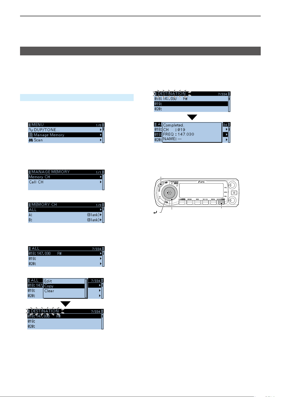
DCopying Memory content to another Memory channel
You can copy the memory content to another Memory
channel.
Example: Copying Memory channel “018” to Memory
channel “019”.
Manage Memory > Memory CH
1. Push [MENU].
2. Rotate [DIAL] to select “Manage Memory,” then
push [ï].
• Displays the MANAGE MEMORY screen.
L You can display the MANAGE MEMORY screen by
pushing [MW] on other than the DR screen.
3. Select “Memory CH,” then push [ï].
4. Select “ALL,” then push [ï].
7. Select the destination channel, then push [ï].
• Beeps sound, and copies to the destination channel.
L If you select a pre-entered channel, the previous
channel content will be overwritten.
[MENU]
[ ]
[DIAL]
[QUICK]
• Displays the ALL screen.
5. Rotate [DIAL] to select the Memory channel “018,”
then push [QUICK].
6. Select “Copy,” then push [ï].
• “DESTINATION” blinks at the top left of the screen.
1-7
1
Previous view
MEMORY OPERATION
Memory bank setting
The transceiver has a total of 26 banks (A ~ Z).
Regular memory channels 0 ~ 999 can be assigned
to any bank for easy memory management. Up to 100
channels can be assigned to a bank.
NOTE: The memory banks are only used to hold
memory channels. Therefore, if the original memory
channel content have been changed, the memory
bank content are also changed at the same time.
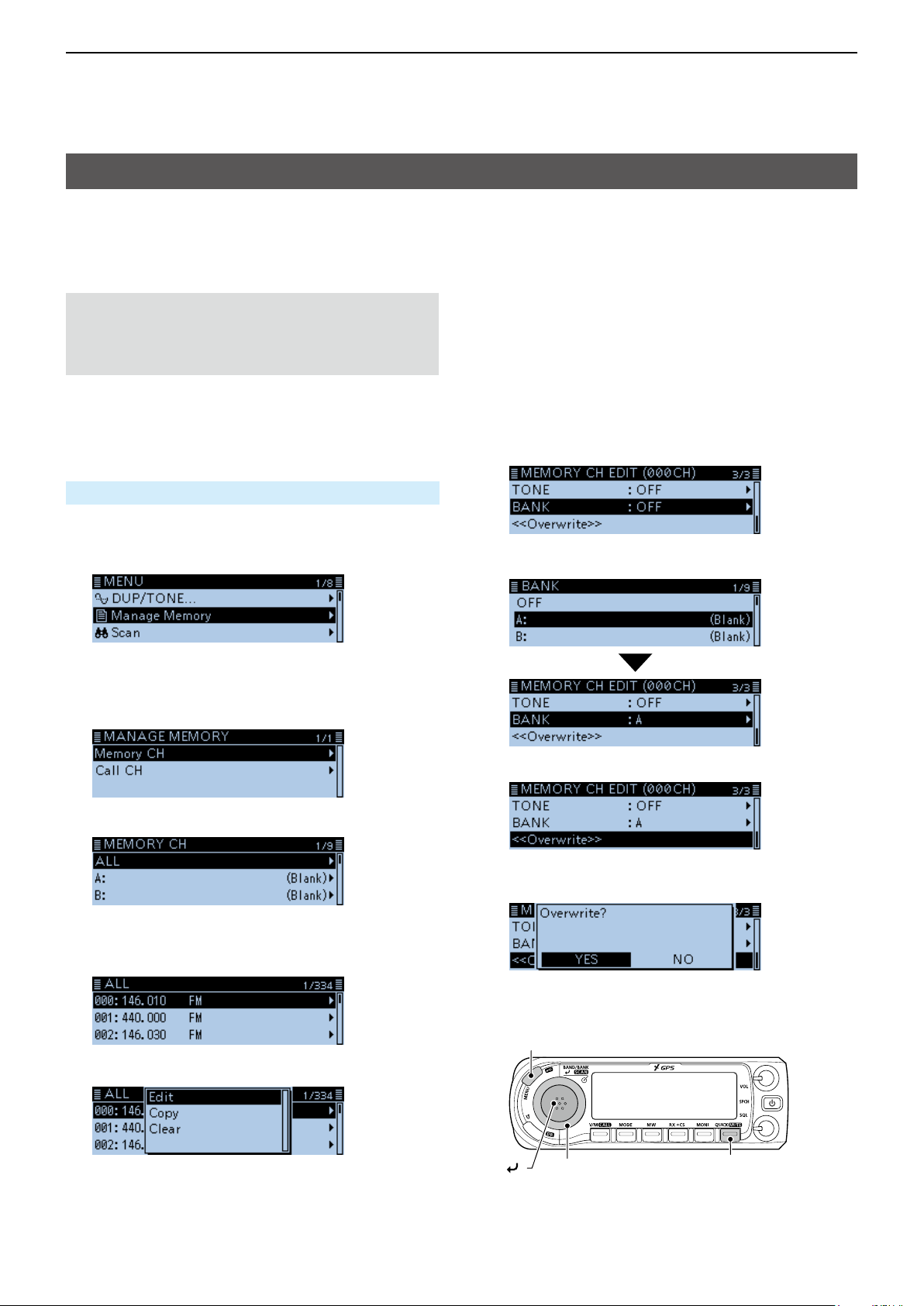
DAssigning a memory channel to a memory bank
Example: Assigning Memory channel “000” to the
bank “A”.
Manage Memory > Memory CH
1. Push [MENU].
2. Rotate [DIAL] to select “Manage Memory,” then
push [ï].
• Displays the MANAGE MEMORY screen.
L You can display the MANAGE MEMORY screen by
pushing [MW] on other than the DR screen.
3. Select “Memory CH,” then push [ï].
4. Select “ALL,” then push [ï].
• Displays the ALL screen.
5. Rotate [DIAL] to select the Memory channel to be
assigned to a bank, then push [QUICK].
7. Select “BANK,” then push [ï].
8. Select a bank to be assigned, then push [ï].
9. Select “<<Overwrite>>,” then push [ï].
• The conrmation dialog “Overwrite?” is displayed.
10. Select <YES>, then push [ï].
• Beeps sound, and assigns the selected memory
channel to the bank.
6. Select “Edit,” then push [ï].
1-8
[MENU]
[ ]
[DIAL]
[QUICK]
1
Previous view
MEMORY OPERATION
Memory bank setting (Continued)
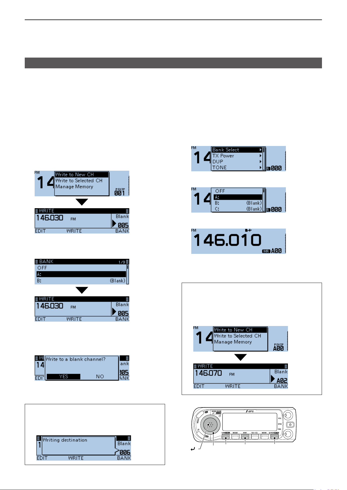
DDirectly writing into a memory bank
You can also write the memory content directly into
a memory bank channel. This way is a short cut to
creating a memory channel, and then assigning it to
a bank. In that case, the transceiver automatically
selects the lowest blank memory channel, to write.
Example: Writing 146.030 MHz into Bank A.
1. Push [V/M] several times until you enter the VFO
mode.
Rotate [DIAL] to set 146.030 MHz.
2.
3.
Push [MW].
4. Rotate [DIAL] to select “Write to New CH,” then
push [ï].
• Displays the WRITE screen.
5. Push [QUICK].
6. Select a bank, then push [ï].
DSelecting the Memory Bank mode
When you select the Memory Bank mode, rotating
[DIAL] selects only the entered bank channels in the
selected bank.
1. Push [V/M] several times until you enter the
Memory mode.
2. Push [QUICK].
3. Rotate [DIAL] to select “Bank Select,” then push
[ï].
4. Select a bank, then push [ï].
5. Rotate [DIAL] to select a bank channel.
L Only assigned bank channels are selectable.
L To return to the Memory mode, select “OFF” in step
4.
7. Push [MW].
• The conrmation dialog “Write to a blank channel?” is
displayed.
8. Select <YES>, then push [ï].
• Beeps sound, and writes the memory content to the
bank channel.
TIP: On the WRITE screen, you can select other
channel by rotating [DIAL].
L If you select a pre-entered channel, the previous
channel content will be overwritten.
TIP: After step 5, you can write the displayed content
to the bank channel.
1. After step 5, push [V/M] to enter the VFO mode.
2. Set the frequency, then push [MW].
3. Rotate [DIAL] to select “Write to New CH,” then
push [ï].
[V/M] [MW] [QUICK]
[DIAL]
[ ]
1-9
1
Previous view
MEMORY OPERATION
Entering a Memory or Bank name
You can enter an alphanumeric name for each
Memory, including Call channels, and Banks.
Names can be a maximum of 16 characters.
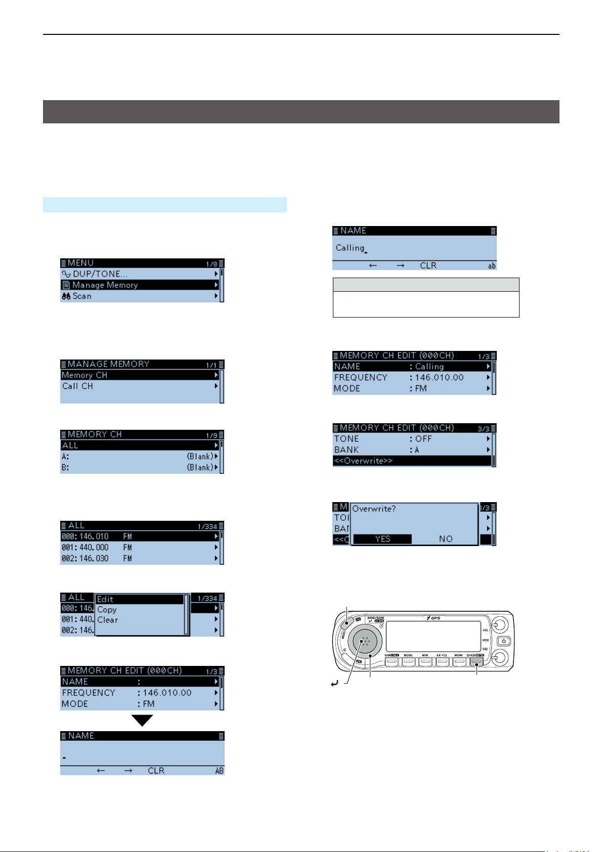
DEntering a Memory name
Manage Memory > Memory CH
1. Push [MENU].
2. Rotate [DIAL] to select “Manage Memory,” then
push [ï].
• Displays the MANAGE MEMORY screen.
L You can display the MANAGE MEMORY screen by
pushing [MW] on other than the DR screen.
3. Select “Memory CH,” then push [ï].
8. Enter a name of up to 16 characters.
(Example: Calling)
Selectable characters and symbols
A to Z, a to z, 0 to 9, ! " # $ % & ’ ( ) * +
, - . / : ; < = > ? @ [ \ ] ^ _ ` { | } ˜ (space)
L See “Entering and editing text” for details. (p. iv)
9. After entering, push [ï].
4. Select “ALL,” then push [ï].
• Displays the ALL screen.
5. Rotate [DIAL] to select the Memory channel to
enter a name, then push [QUICK].
6. Select “Edit,” then push [ï].
7. Select “NAME,” then push [ï].
10. Select “<<Overwrite>>,” then push [ï].
• The conrmation dialog “Overwrite?” is displayed.
11. Select <YES>, then push [ï].
• Beeps sound, and writes the entered name to the
channel.
[MENU]
[ ]
[DIAL]
[QUICK]
• Enters the name entry mode.
1-10
1
Previous view
MEMORY OPERATION
Entering a Memory or Bank name (Continued)
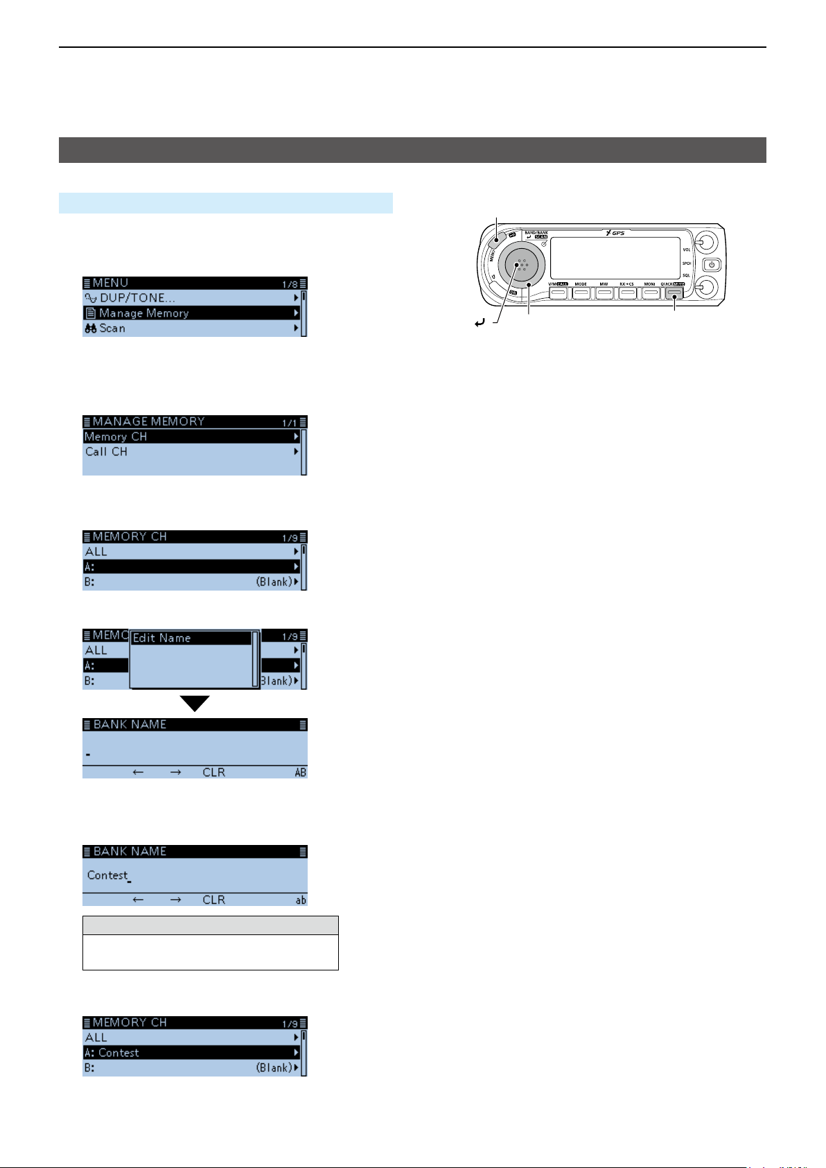
DEntering a Bank name
Manage Memory > Memory CH
1. Push [MENU].
2. Rotate [DIAL] to select “Manage Memory,” then
push [ï].
[MENU]
• Displays the MANAGE MEMORY screen.
L You can display the MANAGE MEMORY screen by
pushing [MW] on other than the DR screen.
3. Select “Memory CH,” then push [ï].
4. Select a bank group to enter a name, then push
[QUICK].
5. Select “Edit Name.”
[ ]
[DIAL]
[QUICK]
6. Enter a bank name of up to 16 characters.
7. After entering, push [ï].
• Enters the bank name entry mode.
(Example: Contest)
Selectable characters and symbols
A to Z, a to z, 0 to 9, ! " # $ % & ’ ( ) * +
, - . / : ; < = > ? @ [ \ ] ^ _ ` { | } ˜ (space)
L See “Entering and editing text” for details. (p. iv)
• Beeps sound, and writes the entered name to the
bank.
1-11
1
Previous view
MEMORY OPERATION
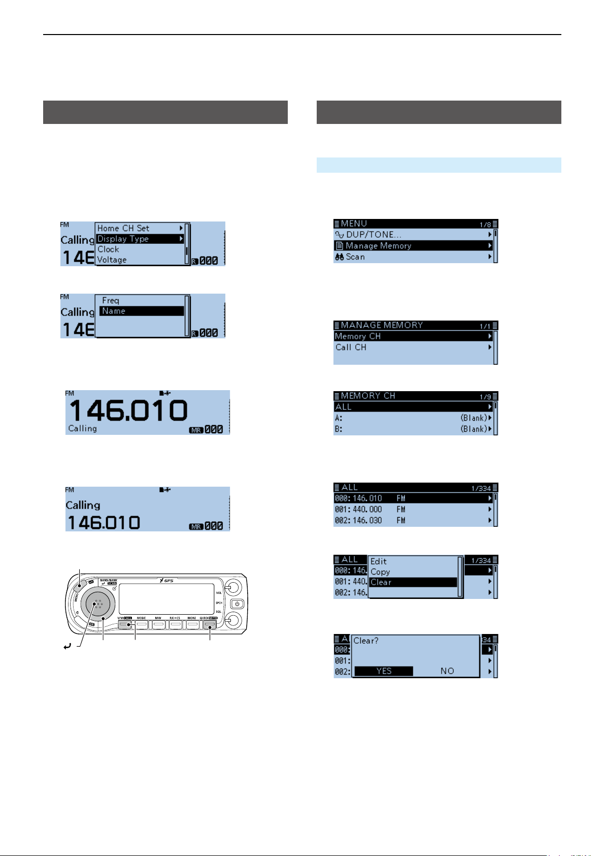
Selecting a Memory name display
The transceiver has two Memory name display types.
1. Push [V/M] several times until you enter the
Memory mode.
2. Push [QUICK].
3. Rotate [DIAL] to select “Display Type,” then push
[ï].
4. Select the display type, then push [ï].
• Freq:
Displays the large font sized frequency and small
font sized memory name.
Clearing a Memory channel
Entered memory content can be cleared.
Manage Memory > Memory CH
1. Push [MENU].
2. Rotate [DIAL] to select “Manage Memory,” then
push [ï].
• Displays the MANAGE MEMORY screen.
L You can display the MANAGE MEMORY screen by
pushing [MW] on other than the DR screen.
3. Select “Memory CH,” then push [ï].
4. Select “ALL,” then push [ï].
• Name:
Displays large font sized memory name and a
small font sized frequency.
[MENU]
[ ]
[DIAL]
[V/M] [QUICK]
• Displays the ALL screen.
5. Rotate [DIAL] to select the Memory channel to be
cleared, then push [QUICK].
6. Select “Clear,” then push [ï].
• The conrmation dialog “Clear?” is displayed.
7. Select <YES>, then push [ï].
• Beeps sound, and clears the memory content.
1-12

Section 2 SCAN OPERATION
Previous view
Scan ....................................................................................... 2-2
D About the scan function .................................................. 2-2
D VFO scan ........................................................................ 2-2
D Memory scan .................................................................. 2-2
D Memory bank scan ......................................................... 2-2
D [DIAL] operation during a scan ....................................... 2-3
D Squelch setting for a scan .............................................. 2-3
D Tuning step for a VFO scan ............................................ 2-3
D Skip function ................................................................... 2-3
D Temporary Skip timer ...................................................... 2-3
D Receive mode during a scan .......................................... 2-3
D When a signal is received ............................................... 2-3
D Scan Stop Beep function ................................................ 2-3
VFO mode scan...................................................................... 2-4
D Scan type ........................................................................ 2-4
D About a Scan name ........................................................ 2-5
D About a Program Link name ........................................... 2-5
D Setting the skip frequencies ............................................ 2-5
Memory scan .......................................................................... 2-6
D Scan type ........................................................................ 2-6
Memory Bank scan ................................................................. 2-7
D Scan type ........................................................................ 2-7
D About a Bank name ........................................................ 2-7
Setting and clearing the skip channel ..................................... 2-8
Entering scan edges .............................................................. 2-9
2-1
2
Previous view
SCAN OPERATION
Scan
Scanning is a versatile function that can automatically
search for signals. A scan makes it easier to locate
stations to contact or listen to, or to skip unwanted
channels or frequencies.
DAbout the scan function
In the VFO mode
The frequencies that are set as “PSKIP” are skipped
during a scan. (p. 2-5, 9-18)
In the Memory mode
Repeatedly scans all entered Memory channels.
The frequencies that are set as skip channels “PSKIP”
and “SKIP” are not scanned. (p. 2-8)
L Two or more Memory channels must be entered to start a
memory scan.
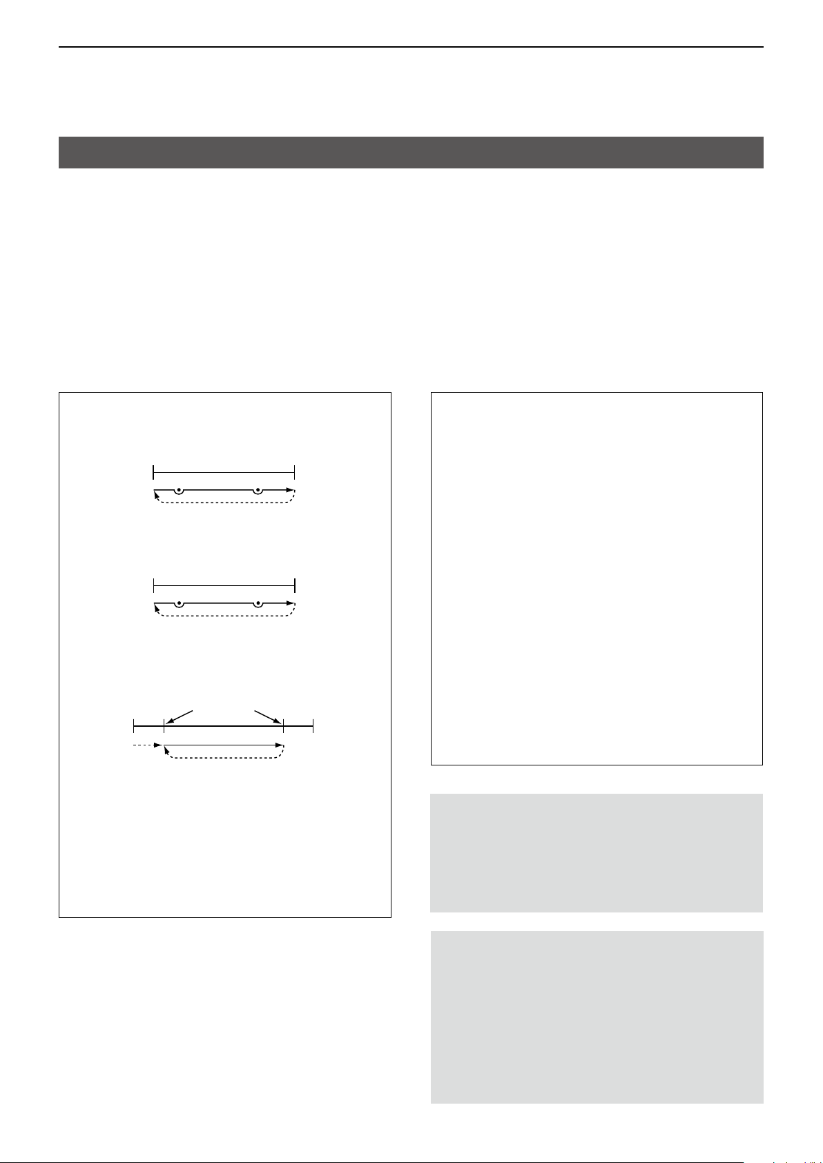
DVFO scan
ALL (Full scan)
Repeatedly scans the entire band.
118 MHz 550 MHz
Scan
P SKIP
Jump
BAND (Selected band scan)
Scans all frequencies over the entire selected band.
Band edge Band edge
Scan
P SKIP
PROG 0 ~ 24 (Program scan)
Scans the Program scan edge ranges.
(Scan > Program Scan Edge) (p. 2-9, 9-18)
Band
edge
Jump
Lower
freq.
Scan edges
L At least one Program scan edge range must be
entered to start a Program scan.
P-LINK0–9 (Program link scan)
Sequentially scans the Program scan edge ranges
which are set to link on the MENU screen.
(p. 9-19)
(Scan > Program Link)
Jump
Scan
Jump
P SKIP
P SKIP
Higher
freq.
Band
edge
DMemory scan
ALL (Memory full scan)
Scans all Memory channels.
BAND (Selected band memory scan)
Scans all Memory channels on the same frequency
band as the selected channel.
MODE (Mode memory scan)
Scans Memory channels which are entered with
the same receiving mode as the currently selected
mode.
DMemory bank scan
ALL (Full bank scan)
Scans all banks.
BANK-LINK (Bank link scan)
Sequentially scans the banks which are set to link
on the MENU screen. (p. 9-18)
(Scan > Bank Link)
BANK-A–Z (Bank scan)
Scans the Memory channels in the selected bank.
Duplex (DUP) scan
The Duplex scan searches for both TX and RX
frequencies which are used in duplex operation.
(p. 8-4)
L “D–” or “D+” is displayed in the Duplex mode.
L A Duplex scan does not start when the frequency
offset is set to “0.000 MHz.”
Tone scan
The Tone scan searches for tone frequencies or
DTCS codes that are used by stations using the
Tone Squelch function.
L A Tone scan is usable in any VFO, Memory, or
Call channel mode.
L During a scan, rotate [DIAL] to change the scan
direction.
See “Tone Squelch function” or “DTCS code
Squelch function” for details. (pp. 10-11, 10-12)
2-2

2
Previous view
SCAN OPERATION
Scan (Continued)
D[DIAL] operation during a scan
• Rotate [DIAL] to change the scan direction during a
scan.
• When the scan is paused, rotate [DIAL] to resume
the scan.
DSquelch setting for a scan
You can change the squelch level to suit your
operating needs. Set the squelch level to open the
squelch, according to the received signal strength.
During a scan, rotate [SQL] to adjust the squelch
level.
DTuning step for a VFO scan
The selected tuning step is applied to the scan.
For a Program scan or Program Link scan, set the
tuning step in the Program Scan Edge ranges.
(p. 2-9)
DSkip function
The skip function speeds up scanning by not scanning
those frequencies set as skip channels. (pp. 2-5, 2-8)
TIP: When “Program Skip” is set to OFF, you cannot
use the Scan Skip function. (p. 9-18)
(Scan > Program skip)
DWhen a signal is received
When a signal is received, the scan pauses for
approximately 10 seconds (default), then resumes.
The scan resumes approximately 2 seconds (default)
after the signal disappears.
To manually resume the scan, rotate [DIAL].
L These settings can be changed on the MENU
screen. (p. 9-18)
(Scan > Pause Timer)
(Scan > Resume Timer)
The S-meter displays the
received signal strength.
DScan Stop Beep function
The Scan Stop Beep function sounds a beep when a
signal is received.
This function can be turned ON or OFF on the MENU
screen. (p. 9-66)
(Sounds > Scan Stop Beep)
When receiving a signal
DTemporary Skip timer
The Temporary Skip function temporarily skips
unwanted frequencies during a scan, for the set
period of time.
• These settings can be changed on the MENU
screen. (p. 9-18)
(Scan > Temporary Skip Timer)
DReceive mode during a scan
• The VFO scan uses the selected receive mode.
L For a Program scan or Program Link scan, set the
tuning step in the Program Scan Edge ranges. (p. 2-9)
• During a Memory or Bank scan, the mode entered
into the channel is used.
Scanning in the FM mode
Displays the scan type
Beeps
2-3
2
Previous view
SCAN OPERATION
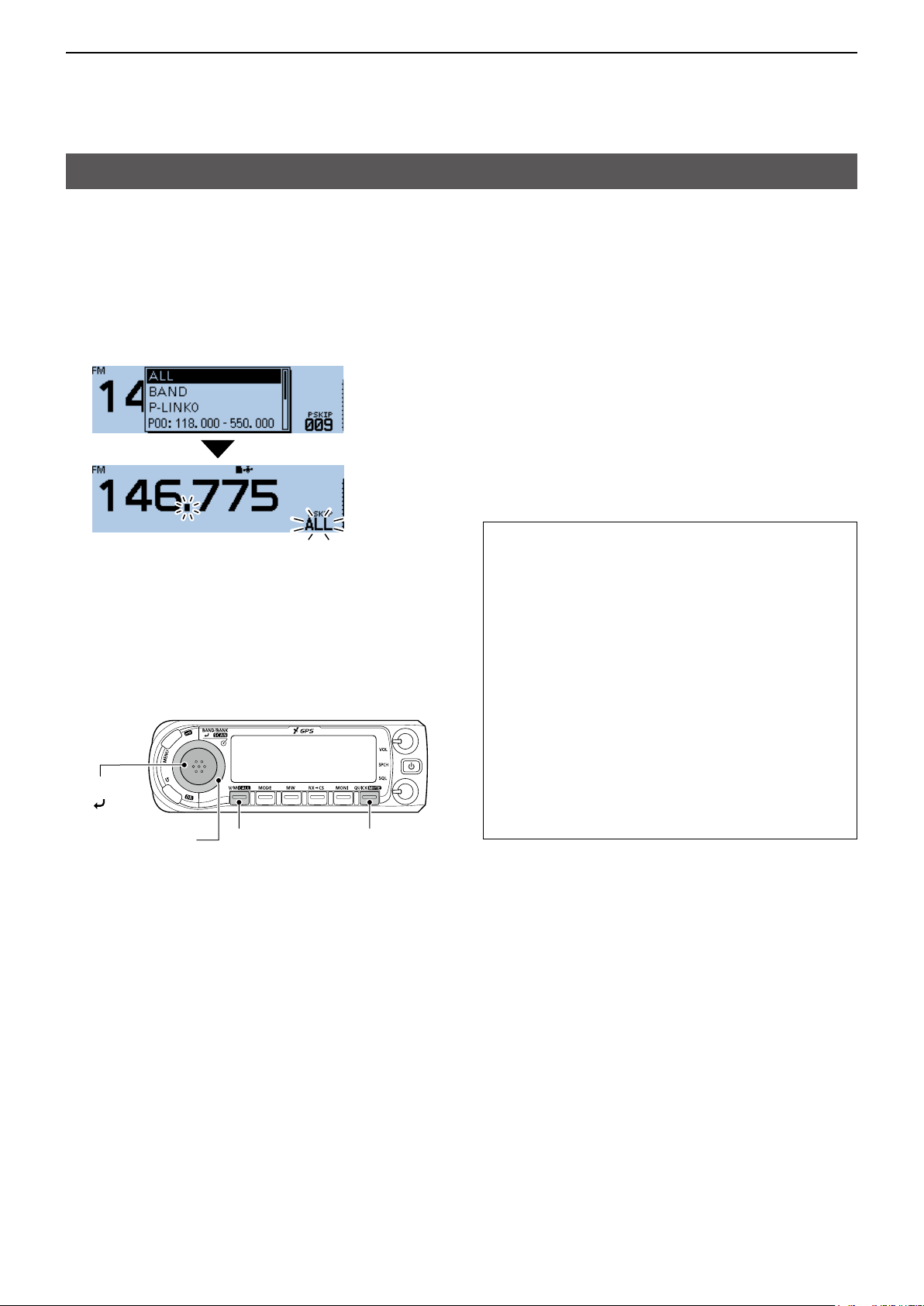
VFO mode scan
1. Push [V/M] several times until you enter the VFO
mode.
2. Hold down [SCAN] for 1 second.
• Opens the Scan Type Select window.
L If you hold down [SCAN] for 3 seconds, the last
selected scan starts.
3. Rotate [DIAL] to select a scan type, then push
[ï].
• The scan starts.
L The decimal point and the selected scan type icon
blink.
L When receiving a signal, the S-meter displays the
received signal strength.
4. Push [SCAN].
• Cancels the scan.
[SCAN]
[ ]*
[DIAL]
[QUICK][V/M]
DScan type
The VFO mode scan has 6 scan types.
• ALL: Full scan
• BAND: Band scan
• P-LINK0 ~ 9: Program link scan
• P00 ~ 24: Program scan
• DUP: Duplex scan
(Displayed only when duplex is set.)
• TONE: Tone scan
(For the Tone Squelch scanning)
L The frequencies that are set as a Skip channel (PSKIP)
are skipped during a scan. (p. 2-8)
L When “Program Skip” is set to “OFF,” the Skip channel
frequencies are not skipped. (p. 9-18)
(Scan > Program Skip)
TIP:
• During a scan, rotating [DIAL] changes the
scanning direction.
• During a scan, you can change the operating
band, scan edge, and so on, in the Quick Menu
window.
• The scan continuously runs, even if you push
[MENU] or [QUICK] during a scan.
• You can set the tuning step and the operating
mode used for a Program scan or Program Link
scan. (p. 2-9)
• The transceiver can receive on the AIR, 144 MHz,
230 MHz, 300 MHz, and 430 MHz bands.*
* Selectable band differs, depending on the transceiver’s
version.
L You can transmit on only the amateur band
frequencies.
*The key operation may differ,
depending on the operating status.
2-4
2
Previous view
SCAN OPERATION
VFO mode scan (Continued)
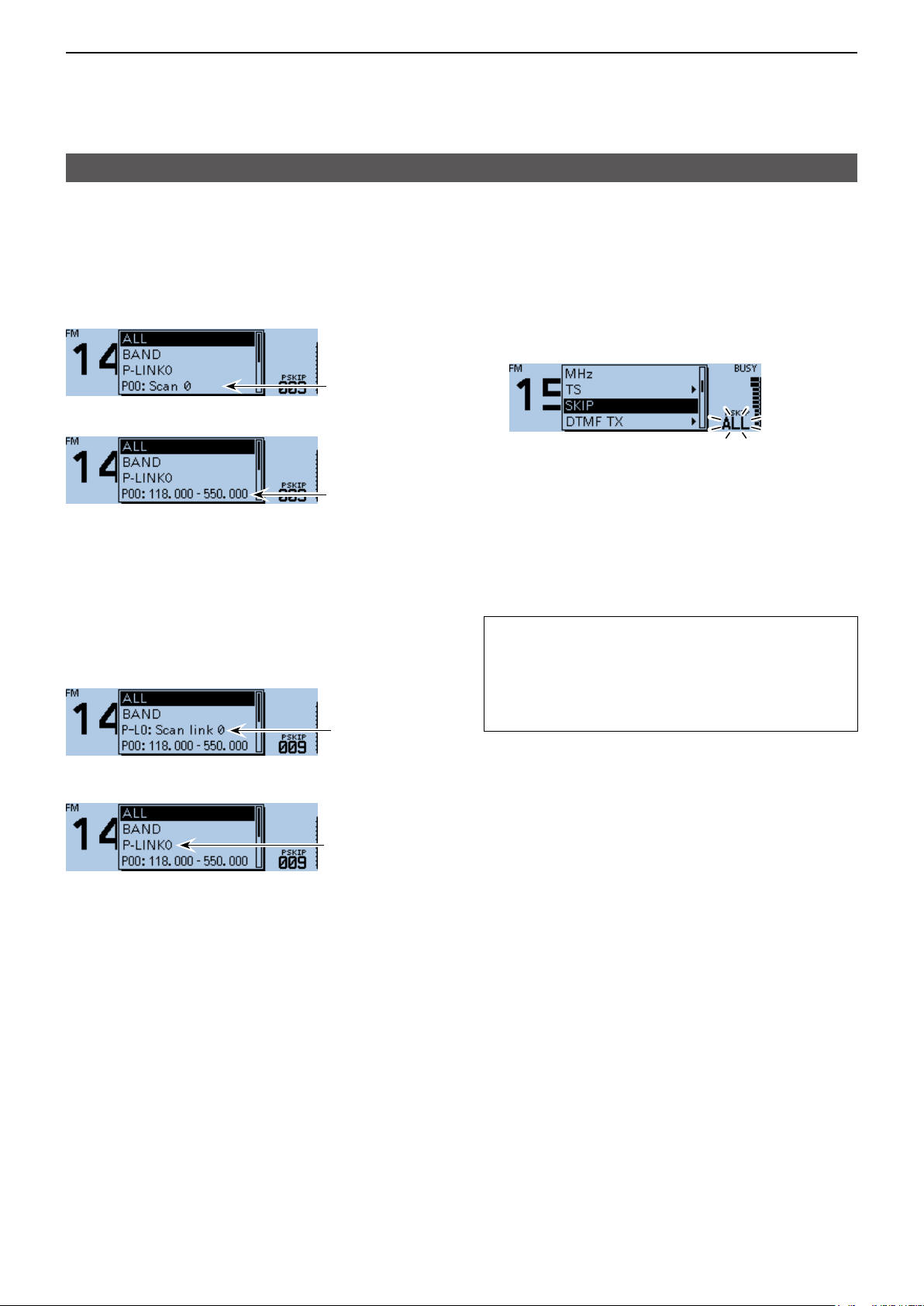
DAbout a Scan name
When a Scan name is assigned, the name is
displayed in the Scan Type Select window. (p. 2-4)
L The Scan name is not displayed during a scan.
L See page 2-9 to enter the scan name.
When the Scan name is assigned
Scan name
When the Scan name is not assigned
Scan edges
DAbout a Program Link name
When a Program Link name is assigned, the name is
displayed in the Scan Type Select window. (p. 2-4)
L The Program Link name is not displayed during a scan.
L See page 2-9 to enter the program link name.
When the Program Link name is assigned
Program
Link name
DSetting the skip frequencies
You can set unnecessary frequencies as Skip
channels (PSKIP) to be skipped during a scan. The
Skip function speeds up a scan.
1. Start the VFO scan.
• When a signal is received, the scan pauses.
2. Push [QUICK].
3. Rotate [DIAL] to select “SKIP.”
• Sets the frequency as a Skip channel into empty
Memory channel 999.
• The entered Memory channel number blinks.
L If channel 999 already has content, the transceiver
automatically searches for another blank channel to
use. If there is no blank channel, a beep sounds, and
the frequency is not set as a Skip channel.
4. After setting, the scan resumes.
TIP: Once frequencies are set as a Skip channel,
these frequencies are skipped until clearing the skip
setting. To clear the skip setting, see page 2-8 for
details.
L The skip setting is also cleared when the Memory
channel set as a Skip channel is cleared. (p. 1-12)
When the Program Link name is not assigned
Program link
2-5

2
Previous view
SCAN OPERATION
Memory scan
NOTE: Two or more Memory channels, which are
not set as Skip channels, must be entered to start a
Memory scan.
1. Push [V/M] several times until you enter the
Memory mode.
2. Hold down [SCAN] for 1 second.
• Opens the Scan Type Select window.
L If you hold down [SCAN] for 3 seconds, the last
selected scan starts.
3. Rotate [DIAL] to select a scan type, then push
[ï].
• The scan starts.
L The decimal point and blink.
L When receiving a signal, the S-meter displays the
received signal strength.
4. Push [SCAN].
• Cancels the scan.
DScan type
The Memory mode scan has 5 scan types.
• ALL: Full scan
• BAND: Band Memory scan
• MODE: Mode Memory scan
• DUP: Duplex scan
(Displayed only when duplex is set.)
• TONE: Tone scan
(For the Tone squelch scanning)
L When two or more Memory channels, which are not
set as Skip channels, are entered, the Memory scan is
usable.
L The channels that are set as a Skip channel (PSKIP or
SKIP) are skipped during a scan. (p. 2-8)
TIP:
• During a scan, rotating [DIAL] changes the
scanning direction.
• The scan continuously runs, even if you push
[MENU] or [QUICK] during a scan.
[SCAN]
[ ]*
[DIAL]
*The key operation may differ,
depending on the operating status.
[V/M]
2-6
2
Previous view
SCAN OPERATION
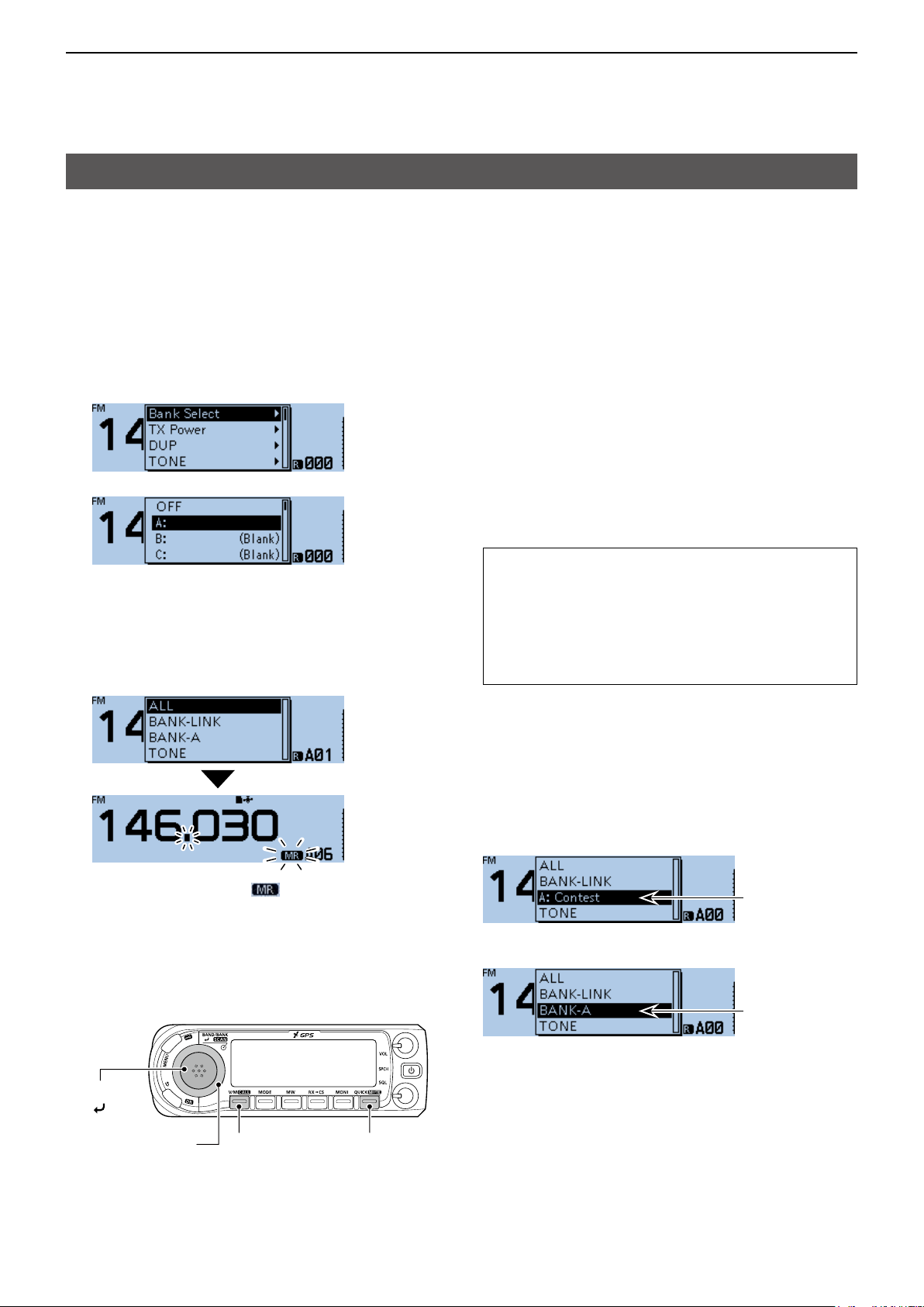
Memory Bank scan
A Memory Bank scan searches through the Memory
channels in the selected bank.
L Two or more Memory channels, which are not set as skip
channels, must be entered to start a Memory Bank scan.
(p. 1-8)
1. Push [V/M] several times until you enter the
Memory mode.
2. Push [QUICK].
3. Rotate [DIAL] to select “Bank Select,” then push
[ï].
4. Select a bank to be scanned, then push [ï].
5. Hold down [SCAN] for 1 second.
• Opens the Scan Type Select window.
L If you hold down [SCAN] for 3 seconds, the last
selected scan starts.
6. Rotate [DIAL] to select a scan type, then push
[ï].
• The scan starts.
DScan type
• ALL: Full bank scan
• BANK-LINK: Bank link scan
• BANK-A ~ Z: Bank scan
( Displays only banks which contain a
Memory channel.)
• DUP: Duplex scan
( Displayed only when duplex is set on
the channel.)
• TONE: Tone scan (For tone scanning)
L When all channels are set as “SKIP” or “PSKIP,” the bank
is skipped during a Bank Link scan. (p. 2-8)
L When all channels in the selected bank are set as “SKIP”
or “PSKIP,” the scan does not start.
L When two or more Memory channels, which are not set
as Skip channels, are entered in a bank, the Memory
bank scan is usable. (p. 2-7)
TIP:
• During a scan, rotating [DIAL] changes the
scanning direction.
• The scan continuously runs, even if you push
[MENU] or [QUICK] during a scan.
• During a scan, you can change the bank to be
scanned on the Quick Menu window.
L The decimal point and blink.
L When receiving a signal, the S-meter displays the
received signal strength.
7. Push [SCAN].
• Cancels the scan.
[SCAN]
[ ]*
[DIAL]
*The key operation may differ,
depending on the operating status.
DAbout a Bank name
When a Bank name is assigned, the name is
displayed on the Scan Type Select window.
L The scan name is not displayed during a scan.
L See page 1-11 to enter the Bank name.
When the Bank name is assigned
Bank name
When the Bank name is not assigned
Bank initial
[QUICK][V/M]
2-7
2
Previous view
SCAN OPERATION
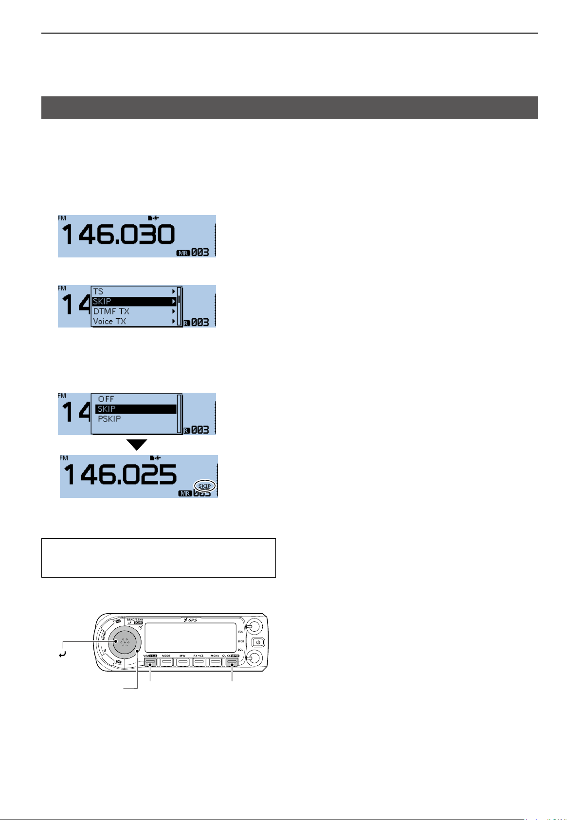
Setting and clearing the skip channel
You can set or clear a Skip channel setting.
The channels that are set as a Skip channel are
skipped during a scan.
1. Push [V/M] several times until you enter the
Memory mode.
2. Rotate [DIAL] to select the Memory channel.
3. Push [QUICK].
4. Rotate [DIAL] to select “SKIP,” then push [ï].
5. Select the option, then push [ï].
• OFF: Cancel the skip setting.
• SKIP: Skipped during a memory scan.
• PSKIP: Skipped during both VFO and memory
scans.
• When a Skip channel is set, “SKIP” or “PSKIP” is
displayed.
TIP: To clear the skip channel setting
To clear the skip channel setting, select “OFF” in
step 5, then push [ï].
[ ]
[DIAL]
[QUICK][V/M]
2-8
2
Previous view
SCAN OPERATION
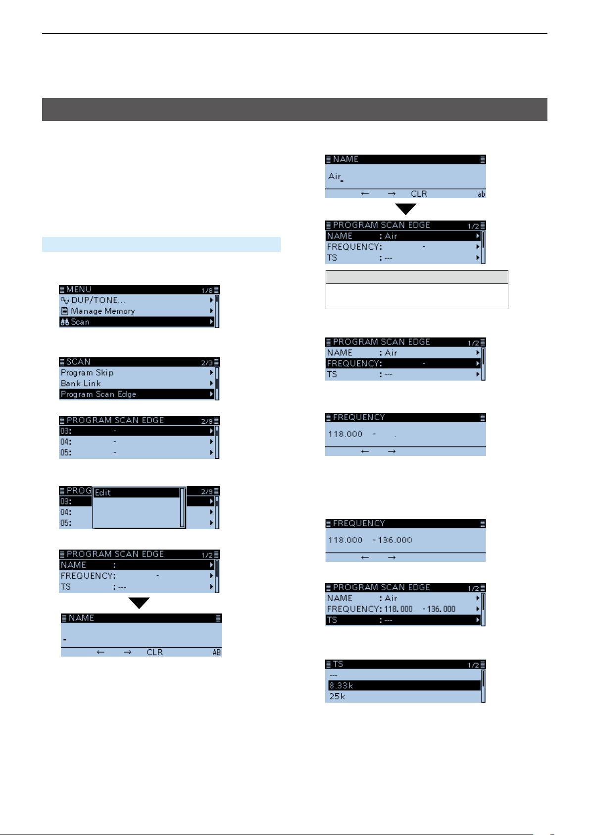
Entering scan edges
You can enter the upper and lower frequency edges to
the Program scan edge ranges for Program scans.
Each Program scan edge range has its own tuning
step and the receive mode.
The default setting is differ, depending on the
transceiver version.
You can enter a total of up to 25 Program scan edge
ranges.
Scan > Program Scan Edge
1. Push [MENU].
2. Rotate [DIAL] to select “Scan,” then push [ï].
• Displays the SCAN screen.
3. Select “Program Scan Edge,” then push [ï].
4. Select a scan edge channel.
8. Enter a name of up to 16 characters, then push
[ï]. (Example: Air)
Selectable characters and symbols
A to Z, a to z, 0 to 9, ! " # $ % & ’ ( ) * +
, - . / : ; < = > ? @ [ \ ] ^ _ ` { | } ˜ (space)
L See “Entering and editing text” for details. (p. iv)
9. Select “FREQUENCY,” then push [ï].
10. Rotate [DIAL] to set a lower frequency, then push
[ï]. (Example: 118000)
5. Push [QUICK].
6. Select “Edit,” then push [ï].
7. Select “NAME,” then push [ï].
• Enter the name entry mode.
L Push [MW] to move the cursor forwards, or push
[MODE] to move the cursor backwards to select a
digit to enter.
11. Set a higher frequency, then push [ï].
(Example: 136000)
12. Select “TS,” then push [ï].
• Displays the selectable tuning step.
13. Select the tuning step to be used during a scan.
L When you select “---,” the tuning step set in the VFO
mode is used during a scan.
☞ Continued on the next page
2-9
2
Previous view
SCAN OPERATION
Entering scan edges (Continued)
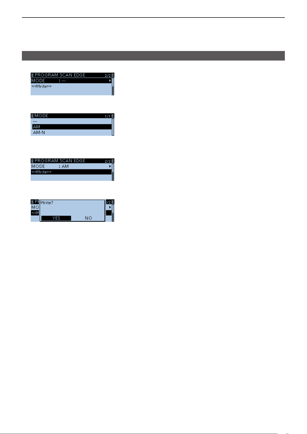
14. Select “MODE,” then push [ï].
• Displays the selectable mode.
15. Select the receive mode to be used during a scan.
L When you select “---,” the receive mode set in the
VFO mode is used during a scan.
16. Select “<<Write>>,” then push [ï].
• The conrmation dialog “Write?” is displayed.
17. Select <YES>, then push [ï].
• Beeps sound, and automatically writes into the
selected scan edge channel.
• Returns to the PROGRAM SCAN EDGE screen.
2-10

Section 3 PRIORITY WATCH
Previous view
Priority watch .......................................................................... 3-2
D Starting the Priority watch ............................................... 3-2
D Canceling the Priority watch ........................................... 3-2
VFO frequency and a Priority channel.................................... 3-3
D When a signal is received ............................................... 3-3
VFO frequency and a Memory/Bank scan.............................. 3-4
D When a signal is received ............................................... 3-4
VFO scan and a Priority channel ............................................ 3-5
D When a signal is received ............................................... 3-5
VFO scan and a Memory/Bank scan ...................................... 3-6
D When a signal is received ............................................... 3-6
Scanning “FROM” on the DR screen and a Priority channel .. 3-7
D When a signal is received ............................................... 3-7
DR scan and a Priority channel .............................................. 3-8
D When a signal is received ............................................... 3-8
3-1
 Loading...