

Page 1

ADVANCED MANUAL
DUAL BAND TRANSCEIVER
ID-4100A
ID-4100E
INTRODUCTION
1 MEMORY OPERATION
2 SCAN OPERATION
3 PRIORITY WATCH
4 D-STAR OPERATION
5 GPS OPERATION
6 USING A microSD CARD
7 VOICE MEMORY
8 REPEATER AND DUPLEX OPERATIONS
9 MENU SCREEN
10 OTHER FUNCTIONS
This manual describes instructions for advanced features and
instructions.
See the Basic manual and the D-STAR guide that come with the
transceiver for precautions, installations, and basic operations.
11 OPTIONS
12 Bluetooth® OPERATION
13 UPDATING THE FIRMWARE
INDEX
Page 2

INTRODUCTION
Previous view
Thank you for choosing this Icom product. This product is designed and built with Icom’ s state of the art technology
and craftsmanship. With proper care, this product should provide you with years of trouble-free operation.
This product combines traditional analog technologies with the new digital technology, Digital Smart Technologies for
Amateur Radio (D-STAR), for a balanced package.
ABOUT THE CONSTRUCTION OF THE MANUAL (As of April 2017)
You can use the following manuals to understand and operate this transceiver.
L If necessary, you can download a glossary of HAM radio terms from the Icom website.
Basic manual (Comes with the transceiver)
Instructions for the basic operations, precautions,
installation, and connections.
D-STAR Guide (Comes with the transceiver)
Instructions for registering your call sign on a gateway
repeater, and the basic operations of D-STAR.
About the DV Gateway function (PDF type)
Instructions on the system requirements or operations
needed to use the DV Gateway function.
L The guide “About the DV Gateway function” can be
downloaded from the Icom website.
Advanced manual (This manual)
Instructions for advanced operations, as shown below.
• Memory operation <Advanced>*
• Scan operation <Advanced>*
• Priority watch operation
• D-STAR operation <Advanced>*
• GPS operation
• Using a microSD card
• Voice memory operation
• Repeater and duplex operations
• Menu screen <Advanced>*
• Other functions
• Options <Advanced>*
• Bluetooth operation
L This manual can be downloaded from the Icom
website.
*The basic instructions are described on the Basic manual.
Icom, Icom Inc. and the Icom logo are registered trademarks of Icom Incorporated (Japan) in Japan, the United States, the United Kingdom,
Germany, France, Spain, Russia, Australia, New Zealand, and/or other countries.
Adobe, Acrobat, and Reader are either registered trademarks or trademarks of Adobe Systems Incorporated in the United States and/or other
countries.
The Bluetooth word mark and logos are registered trademarks owned by the Bluetooth SIG, Inc. and any use of such marks by Icom Inc. is
under license. Other trademarks and trade names are those of their respective owners.
Android and the Android logo are trademarks of Google, Inc.
IOS is a trademark or registered trademark of Cisco in the U.S. and other countries and is used under license.
Apple, iPad, and iPhone are trademarks of Apple Inc., registered in the U.S. and other countries.
App Store is a service mark of Apple Inc.
The iPhone trademark is used under license from AiPhone Co., Ltd.
Galaxy and Galaxy S are registered trademarks of Samsung Electronics Co., Ltd.
Google, the Google Logo, Google Play, the Google Play logo,
All other products or brands are registered trademarks or trademarks of their respective holders.
i
Page 3

INTRODUCTION
Previous view
TABLE OF CONTENTS BY TOPIC
Controller
Attaching/Installing .................... Basic manual (sec. 1)
Front panel ................................ Basic manual (sec. 2)
Display ....................................... Basic manual (sec. 2)
Power key .................................. Basic manual (sec. 3)
Microphone
Connecting ................................ Basic manual (sec. 1)
HM-207S ................................... Basic manual (sec. 2)
Main unit
Connecting to a DC power source
............................................ Basic manual (sec. 1)
Installing in a vehicle ................. Basic manual (sec. 1)
Installing an antenna ................. Basic manual (sec. 1)
Front/Rear panel........................ Basic manual (sec. 2)
Bluetooth
Installing the UT-137..................Basic manual (sec. 1)
Details of Bluetooth operation ...............................12-2
microSD card
Inserting/Removing.................... Basic manual (sec. 7)
Saving the setting data ............................................6-4
Saving with a different le name ..............................6-9
Loading the saved data les that are on a
microSD card ...........................................................6-5
Backing up the data saved on a microSD card
onto a PC.................................................................6-6
Importing or Exporting a CSV formatted le ............6-8
MENU screen/Quick Menu
Quick Menu window .................. Basic manual (sec. 7)
MENU screen ..........................................................9-2
Memory channels
Memory channels ....................................................1-2
Manage Memory screen description .......................1-3
Memory name display ...........................................1-12
Scan
Scan operation
Setting and clearing a Skip channel
Priority Scan operation
........................................................2-2
........................2-8
............................................3-2
GPS
GPS operation .........................................................5-2
Checking your GPS position....................................5-3
Checking GPS information (Sky view screen) ....... 5-11
Transmitting D-PRS data ............................. 5-12, 5-13
Transmitting NMEA data .............................. 5-12, 5-25
GPS Logger function .............................................5-34
GPS Auto transmission..........................................5-38
D-STAR
Register your call sign on a
gateway repeater
“FROM” (Access repeater) setting...........................4-3
“TO” (Destination) setting ........................................4-8
Connecting to a Reector ......................................4-13
Message operation ................................................4-17
Viewing the received call signs ..............................4-19
BK mode communication.......................................4-21
EMR communication .............................................4-22
Automatic DV detection .........................................4-23
Automatic Reply function .......................................4-24
Data communication ..............................................4-27
Digital call sign squelch/
Digital code squelch functions ...............................4-29
Viewing call signs ..................................................4-31
Repeater list ..........................................................4-32
Adding Repeater information
using the RX History ..............................................4-39
Skip setting for a DR scan .....................................4-40
Entering a repeater group name............................4-41
Repeater detail screen ..........................................4-42
Entering Your (destination) call sign ......................4-43
REPEATER AND DUPLEX OPERATIONS
Duplex operation .....................................................8-4
Auto repeater function .............................................8-5
Off band indication ...................................................8-5
VOICE MEMORY
Recording a QSO audio ..........................................7-2
Playing back the recorded audio .............................7-3
Changing the QSO recorder settings ......................7-4
Deleting the audio folder/le ....................................7-5
Viewing the le information ......................................7-6
Viewing the microSD card memory capacity ...........7-7
Playing back the recorded audio on the PC ............7-8
...................................D-STAR Guide
ii
Page 4
INTRODUCTION
Previous view
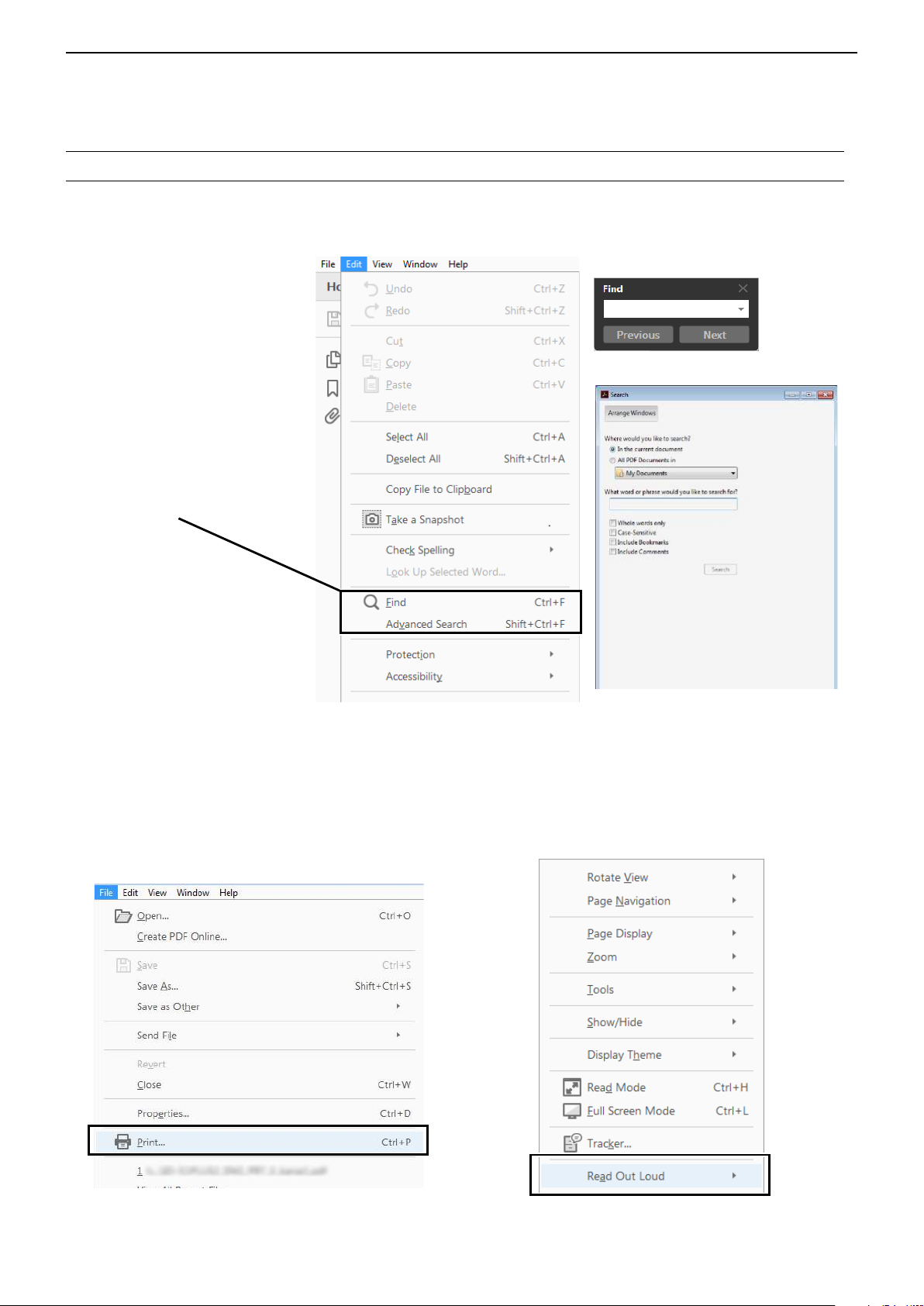
Functions and features of Adobe® Acrobat® Reader
The following functions and features can be used with Adobe® Acrobat® Reader®.
• Keyword search
Click “Find” (Ctrl+F) or “Advanced
Search” (Shift+Ctrl+F) in the Edit
menu to open the search screen.
This is convenient when search-
ing for a particular word or phrase
in this manual.
* The menu screen may differ,
depending on the Adobe
Reader® version.
®
Acrobat
®
Click to open the find or search
screen or advanced search screen.
• Find screen
• Advanced search screen
®
• Printing out the desired pages.
Click “Print” in the File menu, and then select the
paper size and page numbers you want to print.
* The printing setup may differ, depending on the
printer. Refer to your printer’s instruction manual
for details.
* Select "A4" size to print out the page in the original
manual size.
• Read Out Loud feature.
The Read Out Loud feature reads aloud the text in
this PDF.
Refer to the Adobe
®
Acrobat® Reader® Help for the
details.
( This feature may not be usable, depending on your
PC environment including the operating system.)
* The screen may differ, depending on the Adobe® Acrobat® Reader®
version.
iii
Page 5
INTRODUCTION
Previous view
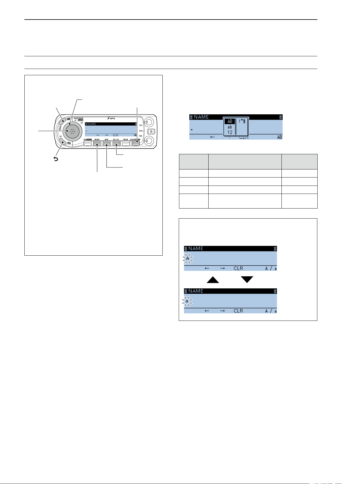
Entering and editing text
Controls used for text entry
[QUICK]
[MENU]
Cancels
[DIAL] (Rotate)
Selects
Selects the
character type
[ï]
Sets
[]
Cancels
[MODE]
Moves the
cursor to the left
[RX→CS]
Clears
[MW]
Moves the
cursor to the
right
• To insert a text, move the cursor to a place to
enter, then rotate [DIAL].
• To clear a character, push [RX→CS].
• To consecutively clear characters, continuously
hold down [RX→CS].
• When the character type is “AB” or “ab,” and while
entering a character, push [QUICK] to convert
between upper case and lower case letters.
To change the character type
1. When not selecting text, or an entered text is
selected, push [QUICK].
2. Rotate [DIAL] to select the character type, then
push [ï].
Character
type
AB
ab
12
!”#
Selectable characters
and symbols
A to Z, (space)
a to z, (space)
0 to 9, (space)
! " # $ % & ’ ( ) * + , - . / : ; < =
> ? @ [ \ ] ^ _ ` { | } ˜ (space)
Character
conversion
A/a
A/a
–
–
TIP: When the character type is “AB” or “ab,” and
while entering a character, push [QUICK] to convert
between upper case and lower case letters.
Push
[QUICK]
iv
Page 6
INTRODUCTION
Previous view
Entering and editing text (Continued)
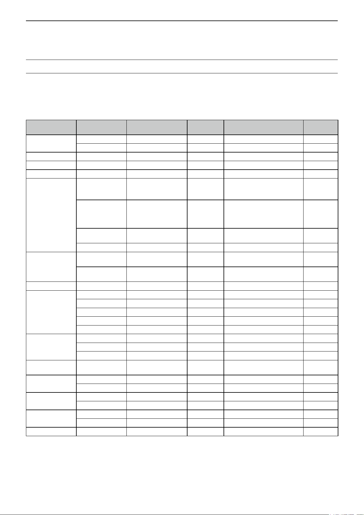
DUsable characters
The usable characters and symbols, and the maximum characters differ, depending on the item.
See the following list for details.
L The usable characters and symbols for each character type are described at the bottom of the page.
Category Item Character type
Manage Memory
Program scan Scan name [AB] [ab] [12] [!”#] 16 – p. 2-9
P-LINK Scan Link name [AB] [ab] [12] [!”#] 16 – p. 9-20
My Station TX Message [AB] [ab] [12] [!”#] 20 – p. 4-17
GPS TX Mode
SD Card
Bluetooth Set Device name [AB] [ab] [12] [!”#] 8 Except for “ICOM BT-” p. 9-72
Repeater List
CS screen
My Call Sign Call sign A to Z, 0 to 9, /, space 12 (+1)
Your Call sign
GPS Memory
DR screen
DTMF Memory DTMF code 0 to 9, A, B, C, D, *, # 24 – p. 10-8
Memory name [AB] [ab] [12] [!”#] 16 – p. 1-10
Bank name [AB] [ab] [12] [!”#] 16 – p. 1-11
Unproto Address [AB] [ab] [12] [!”#] 56
Comment [AB] [ab] [12] [!”#] 43
Object Name
Item Name
GPS Message [AB] [ab] [12] [!”#] 20 – p. 5-26
Save Setting [AB] [ab] [12] [!”#] 20
Export [AB] [ab] [12] [!”#] 20
Group name [AB] [ab] [12] [!”#] 16 – p. 4-41
Repeater name [AB] [ab] [12] [!”#] 16 – p. 4-34
Sub name [AB] [ab] [12] [!”#] 8 – p. 4-34
Call sign A to Z, 0 to 9, /, space 8 – p. 4-34
GW Call sign A to Z, 0 to 9, /, space 8 – p. 4-34
UR A to Z, 0 to 9, /, space 8 – p. 9-41
R1 A to Z, 0 to 9, /, space 8 – p. 9-41
R2 A to Z, 0 to 9, /, space 8 – p. 9-41
Name [AB] [ab] [12] [!”#] 16 – p. 4-43
Call sign A to Z, 0 to 9, /, space 8 p. 4-43
Memory name [AB] [ab] [12] [!”#] 16 – p. 5-27
Group name [AB] [ab] [12] [!”#] 16 – p. 5-30
Direct Input (UR) A to Z, 0 to 9, /, space 8 – p. 4-11
Direct Input (RPT) A to Z, 0 to 9, /, space 8 – p. 4-12
[AB] [ab] [12] [!”#] 9 – p. 5-17
Maximum
characters
Information Reference
Normally 12 characters
(API410,DSTAR*)
The number of characters you
can enter differs, depending on
the data extension and altitude
settings.
Illegal characters:
/ : ; * < >
Illegal characters:
/ : ; * < >
Includes “/” between the Call
sign and Memo field.
p. 5-15
p. 5-17
p. 5-21
p. 5-16
p. 5-18
p. 5-22
p. 6-4
p. 6-9
p. 9-47
[AB]: A to Z, (space)
[ab]: a to z, (space)
[12]: 0 to 9, (space)
[!”#]: ! " # $ % & ’ ( ) * + , - . / : ; < = > ? @ [ \ ] ^ _ ` { | } ˜ (space)
v
Page 7
INTRODUCTION
Previous view
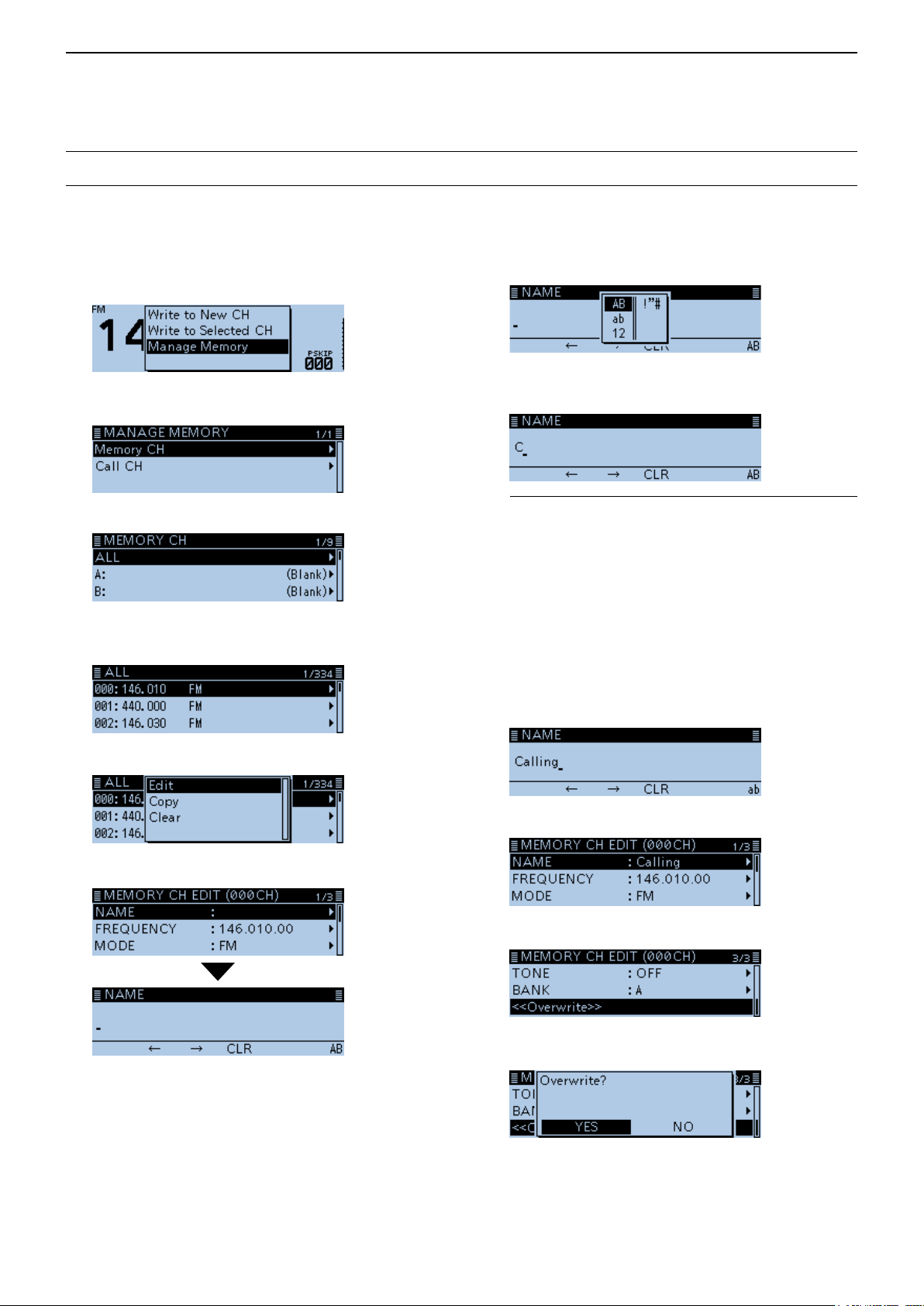
Entering and editing text (Continued)
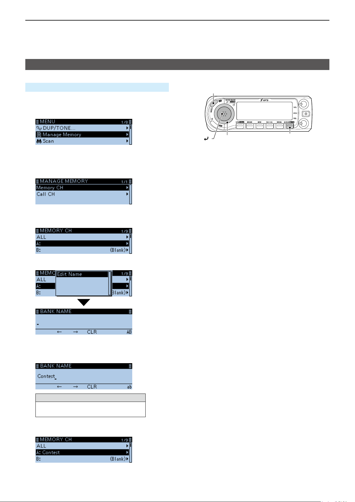
DHow to enter
(Example: Entering “Calling” as a Memory name.)
1. Push [MW].
2. Rotate [DIAL] to select “Manage Memory,” then
push [ï].
8. Push [QUICK].
9. Select the character type, then push [ï].
• Displays the MANAGE MEMORY screen.
3. Select “Memory CH,” then push [ï].
4. Select “ALL,” then push [ï].
• Displays the ALL screen.
5. Rotate [DIAL] to select the Memory channel to
enter a name, then push [QUICK].
6. Select “Edit,” then push [ï].
10. Rotate [DIAL] to select a character, then push [ï].
(Example: C)
InformationL
• To move the cursor forward, push [MW].
• To move the cursor backward, push [MODE].
• To insert a text, move the cursor to a place to enter,
then rotate [DIAL].
• To clear a character, push [RX→CS].
• To consecutively clear characters, continuously hold
down [RX→CS].
• When the character type is “AB” or “ab,” and while
entering a character, push [QUICK] to convert
between upper case and lower case letters.
11. Repeat step 8 ~ 10 to enter a name.
(Example: Calling)
12. After entering, push [ï].
7. Select “NAME,” then push [ï].
• Enters the name entry mode.
13. Select “<<Overwrite>>,” then push [ï].
• The conrmation dialog “Overwrite?” is displayed.
14. Select <YES>, then push [ï].
• Beeps sound, and writes the entered name to the
channel.
vi
Page 8

Section 1 MEMORY OPERATION
Previous view
General description ................................................................ 1-2
D The number of the Memory channel ............................... 1-2
D Memory channel content ................................................ 1-2
Manage Memory screen description ...................................... 1-3
D Tree view of the Manage Memory screen ....................... 1-3
D Displaying the Manage Memory screen ......................... 1-3
Selecting a Memory channel .................................................. 1-4
Selecting a Call channel ......................................................... 1-4
Writing to a Memory channel .................................................. 1-5
D Writing to the selected channel ....................................... 1-5
D Writing to a blank channel............................................... 1-5
D Overwriting to the selected channel ................................ 1-6
D Copying Memory content to the VFO ............................. 1-6
D Copying Memory content to another Memory channel ... 1-7
Memory bank setting .............................................................. 1-8
D Assigning a memory channel to a memory bank ............ 1-8
D Directly writing into a memory bank ................................ 1-9
D Selecting the Memory Bank mode .................................. 1-9
Entering a Memory or Bank name ....................................... 1-10
D Entering a Memory name ............................................. 1-10
D Entering a Bank name ...................................................1-11
Selecting a Memory name display........................................ 1-12
Clearing a Memory channel.................................................. 1-12
1-1
Page 9

1
Previous view
MEMORY OPERATION
General description
The transceiver has a total of 1000 Memory channels
(100 channels in each of 26 memory banks, A ~ Z)
and two Call channels (C0/C1) each for the 144 and
430 MHz bands.
The Memory mode is useful to quickly select oftenused frequencies.
DThe number of the Memory channel
Memory Channels Descriptions
000 ~ 999 (Total of 1000) Regular Memory channels.
C0/C1
Two Call channels (C0/C1) each for the 144 and 430 MHz bands.
Instantly recalls a specied frequency.
DMemory channel content
The following information can be entered into the
Memory channels:
• Operating frequency
• Duplex direction (DUP+ or DUP–) and frequency
offset
• Memory name
• Scan skip setting
• Tuning step
• Operating mode
• Subaudible tone encoder, tone squelch or DTCS
squelch ON/OFF
• Subaudible tone frequency, tone squelch frequency
or DTCS code with polarity
• UR station call sign
• R1/R2 call signs
• Digital Call sign squelch or Digital code squelch ON/
OFF
• Digital code
• Memory bank
NOTE: Memory content may be accidentally
cleared by static electricity, electric transients,
and other causes. In addition, it may be cleared
by a malfunction, or during repairs. Therefore, we
recommend that you backup the memory content or
save it to a microSD card* or to a PC.
*User supplied
L The CS-4100 cloning software can also be used to
backup your memory data.
1-2
Page 10
1
Previous view
MEMORY OPERATION
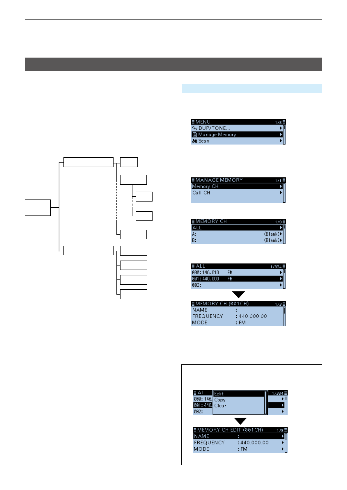
Manage Memory screen description
The MANAGE MEMORY screen enables you to easily
manage the Memory or Call channel content.
• Displays the Memory or Call channel content.
• Easy to assign to a bank, and displays the bank
content.
• Easy to add, edit, copy, or clear the Memory
channels.
DTree view of the Manage Memory screen
Memory CH
Manage
Memory
ALL
Bank A
A00
A99
Bank Z
DDisplaying the Manage Memory screen
Manage Memory > Memory CH
1. Push [MENU].
2. Rotate [DIAL] to select “Manage Memory,” then
push [ï].
• Displays the MANAGE MEMORY screen.
L You can display the MANAGE MEMORY screen by
pushing [MW] on other than the DR screen.
3. Select “Memory CH,” then push [ï].
4. Select “ALL,” then push [ï].
Call CH
C0 144
C1 144
C0 430
C1 430
• Displays the ALL screen.
5. Select a channel, then push [ï].
• Displays the Memory content.
L Rotate [DIAL] to select the page.
6. Push [MENU].
• Returns to the standby screen.
TIP: To edit, copy or clear the memory content.
1. Push [QUICK] in step 5.
2. Select “Edit,” “Copy” or “Clear,” then push [ï].
(Example: When selecting “Edit.”)
1-3
Page 11
1
Previous view
MEMORY OPERATION
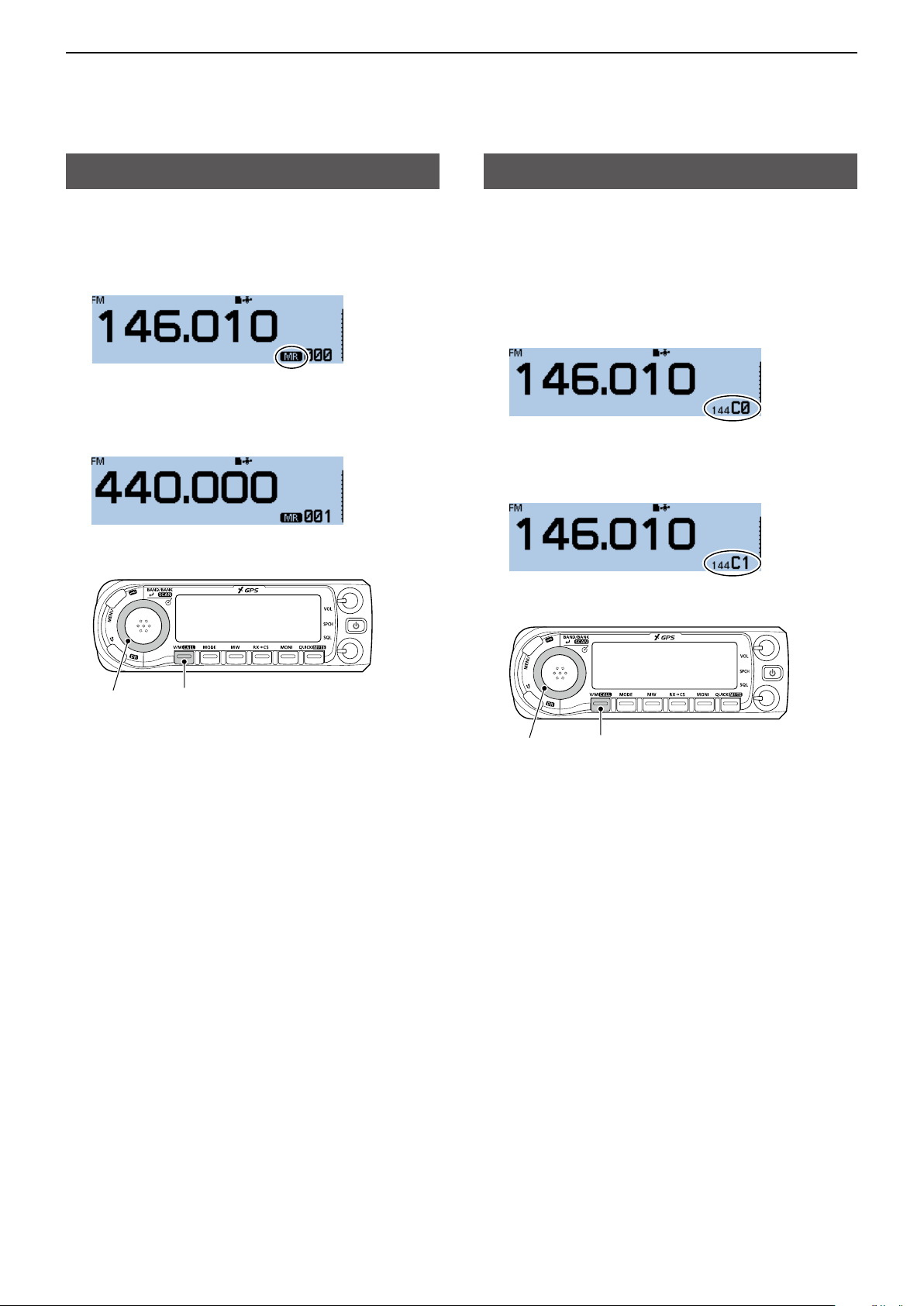
Selecting a Memory channel
In the Memory mode, you can select the Memory
channels by rotating [DIAL].
1. Push [V/M] several times until you enter the
Memory mode.
L Pushing [V/M] toggles between the VFO and Memory
modes.
2. Rotate [DIAL].
• Selects a Memory channel.
L Blank channels are not selectable.
Selecting a Call channel
Two Call channels (C0/C1) are selectable in each of
the 144 and 430 MHz bands.
Factory default frequencies and operating modes are
entered into the Call channels. Change these to suit
your operating needs.
1. Hold down [CALL] for 1 second.
• Enters the Call channel mode.
L Pushing [CALL] again cancels the Call channel
mode.
2. Rotate [DIAL].
• Selects a Call channel.
[DIAL]
[V/M]
[DIAL]
[CALL]
1-4
Page 12
1
Previous view
MEMORY OPERATION
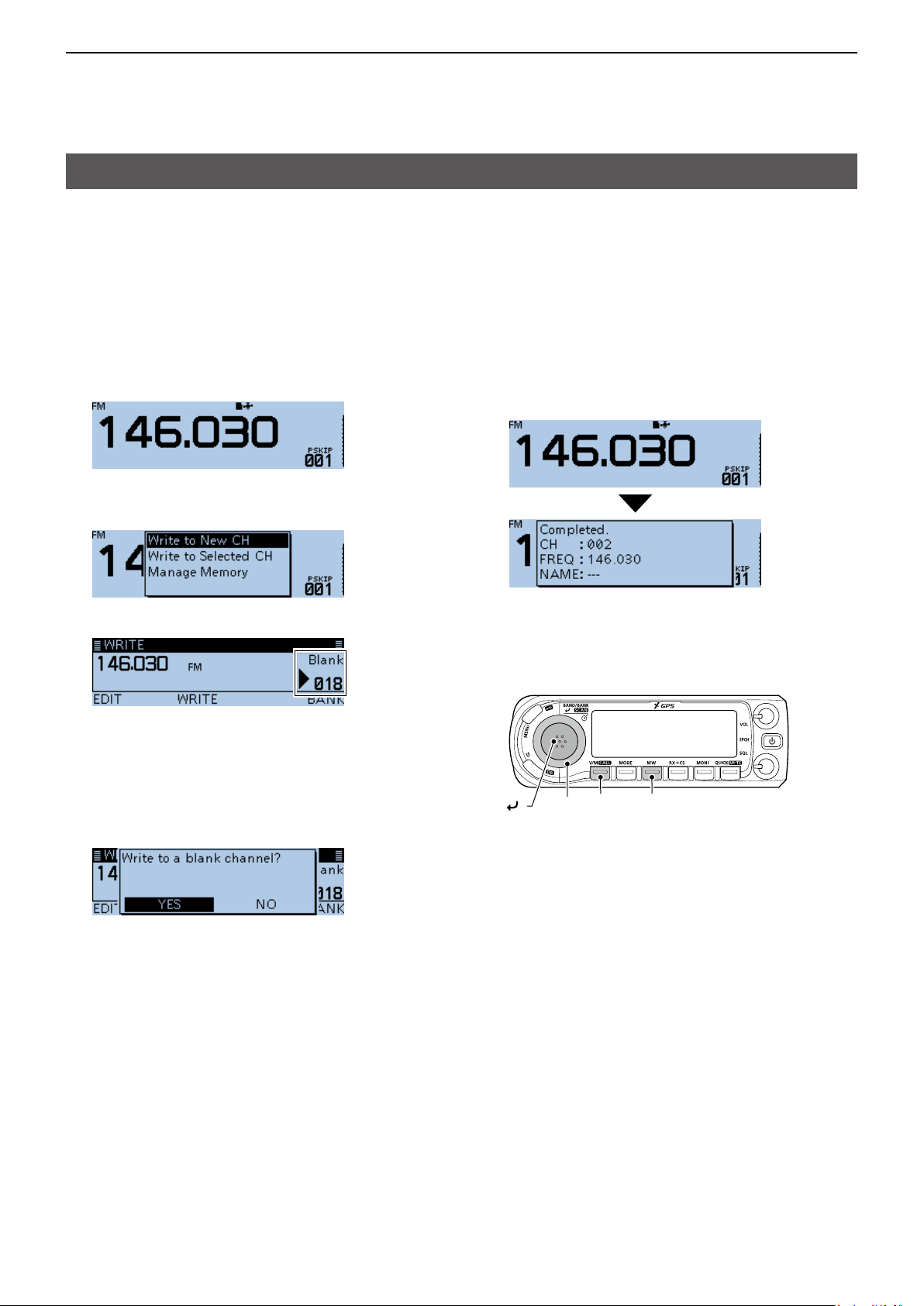
Writing to a Memory channel
After setting a frequency in the VFO mode, you can
write it to a selected channel or an automatically
selected blank channel.
Memory channels 002 to 999 are blank as the default.
DWriting to the selected channel
Example: Writing 146.030 MHz into Memory channel 18.
1. Push [V/M] several times until you enter the VFO
mode.
2. Rotate [DIAL] to select 146.030 MHz.
3. Push [MW].
4. Rotate [DIAL] to select “Write to New CH.”
5. Rotate [DIAL] to select the Memory channel “018.”
L If you select a pre-entered channel, the previous
channel content will be overwritten.
L The Call channels are also selectable.
6. Push [MW].
• The conrmation dialog “Write to a blank channel?” is
displayed.
7. Select <YES>, then push [ï].
DWriting to a blank channel
Example: Writing 146.030 MHz into a blank channel.
1. Push [V/M] several times until you enter the VFO
mode.
2. Rotate [DIAL] to set 146.030 MHz.
3. Hold down [MW] for 1 second.
• Beeps sound, and automatically writes into a blank
channel.
• Returns to the standby screen (VFO mode).
[V/M] [MW]
[DIAL]
[ ]
• Beeps sound, and writes into the selected Memory
channel.
• Returns to the standby screen (VFO mode).
1-5
Page 13
1
Previous view
MEMORY OPERATION
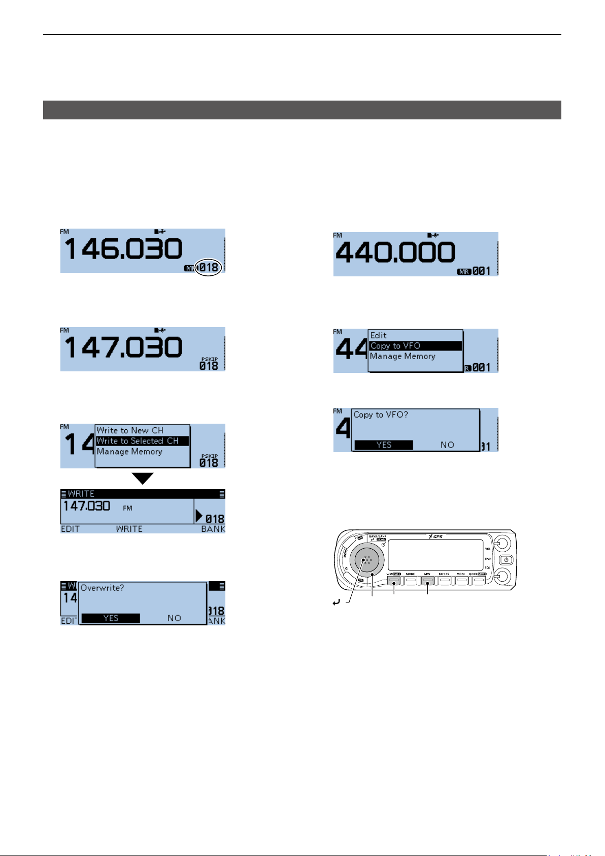
Writing to a Memory channel (Continued)
DOverwriting to the selected channel
You can write a frequency into a pre-entered channel.
Example: Writing 147.030 MHz into Memory channel
“018.”
1. Push [V/M] several times until you enter the
Memory mode.
2. Rotate [DIAL] to select the channel 18.
Destination channel
3. Push [V/M] to enter the VFO mode.
4. Rotate [DIAL] to set 147.030 MHz.
5. Push [MW].
6. Rotate [DIAL] to select “Write to Selected CH,”
then push [ï].
DCopying Memory content to the VFO
It is convenient when you want to operate on a
channel frequency near a Memory or Call channel.
Example: Copying Memory channel “001” to the VFO.
1. Push [V/M] several times until you enter the
Memory mode.
2. Rotate [DIAL] to select the channel 1.
3. Push [MW].
4. Rotate [DIAL] to select “Copy to VFO,” then push
[ï].
• The conrmation dialog “Copy to VFO?” is displayed.
5. Select <YES>, then push [ï].
7. Push [MW].
• The conrmation dialog “Overwrite?” is displayed.
8. Select <YES>, then push [ï].
• Beeps sound, and writes into the selected Memory
channel.
• Returns to the standby screen (VFO mode).
• Beeps sound, and copies the selected Memory
content to the VFO.
• Returns to the standby screen (VFO mode).
[V/M] [MW]
[DIAL]
[ ]
1-6
Page 14
1
Previous view
MEMORY OPERATION
Writing to a Memory channel (Continued)
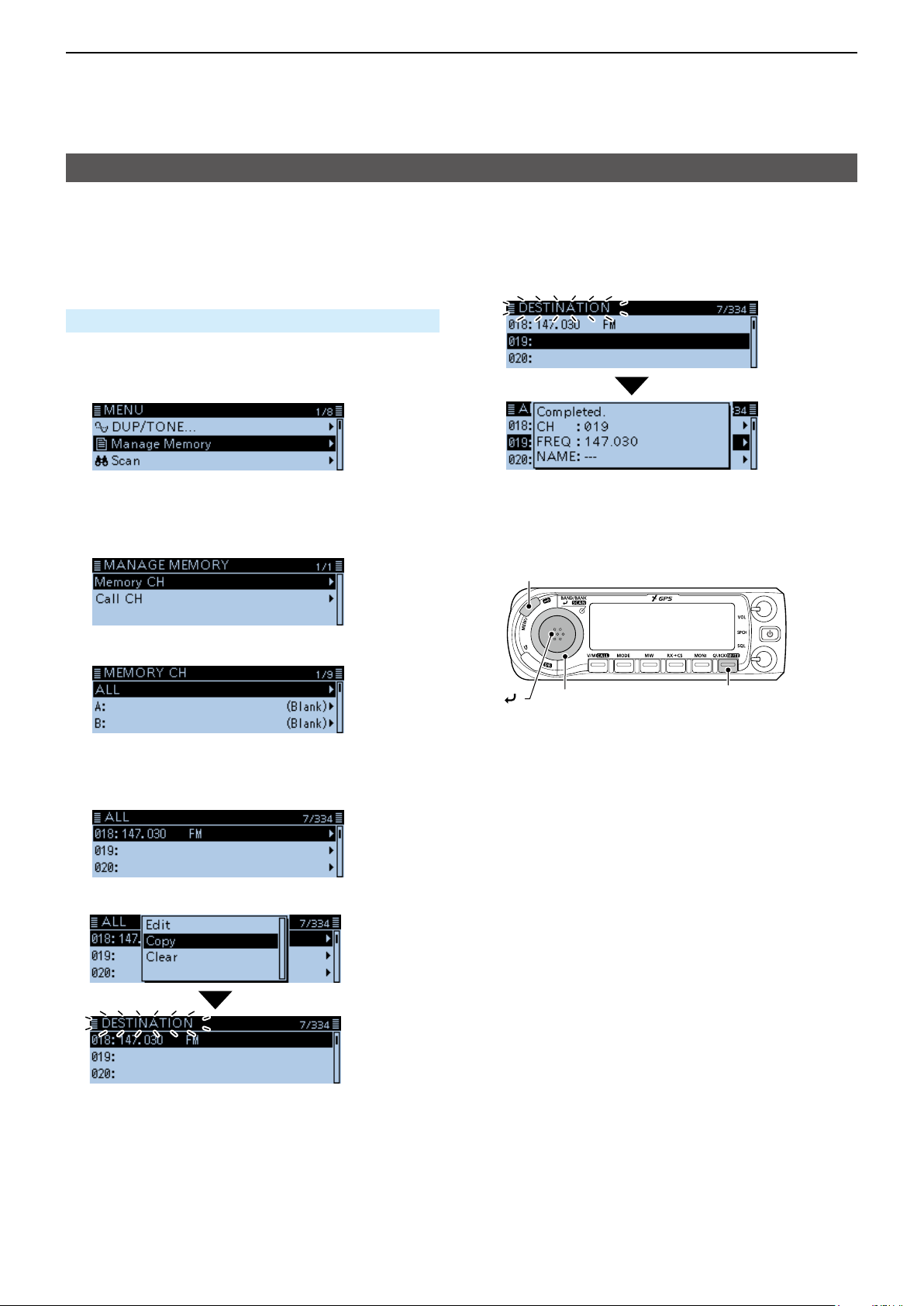
DCopying Memory content to another Memory channel
You can copy the memory content to another Memory
channel.
Example: Copying Memory channel “018” to Memory
channel “019”.
Manage Memory > Memory CH
1. Push [MENU].
2. Rotate [DIAL] to select “Manage Memory,” then
push [ï].
• Displays the MANAGE MEMORY screen.
L You can display the MANAGE MEMORY screen by
pushing [MW] on other than the DR screen.
3. Select “Memory CH,” then push [ï].
4. Select “ALL,” then push [ï].
7. Select the destination channel, then push [ï].
• Beeps sound, and copies to the destination channel.
L If you select a pre-entered channel, the previous
channel content will be overwritten.
[MENU]
[ ]
[DIAL]
[QUICK]
• Displays the ALL screen.
5. Rotate [DIAL] to select the Memory channel “018,”
then push [QUICK].
6. Select “Copy,” then push [ï].
• “DESTINATION” blinks at the top left of the screen.
1-7
Page 15
1
Previous view
MEMORY OPERATION
Memory bank setting
The transceiver has a total of 26 banks (A ~ Z).
Regular memory channels 0 ~ 999 can be assigned
to any bank for easy memory management. Up to 100
channels can be assigned to a bank.
NOTE: The memory banks are only used to hold
memory channels. Therefore, if the original memory
channel content have been changed, the memory
bank content are also changed at the same time.
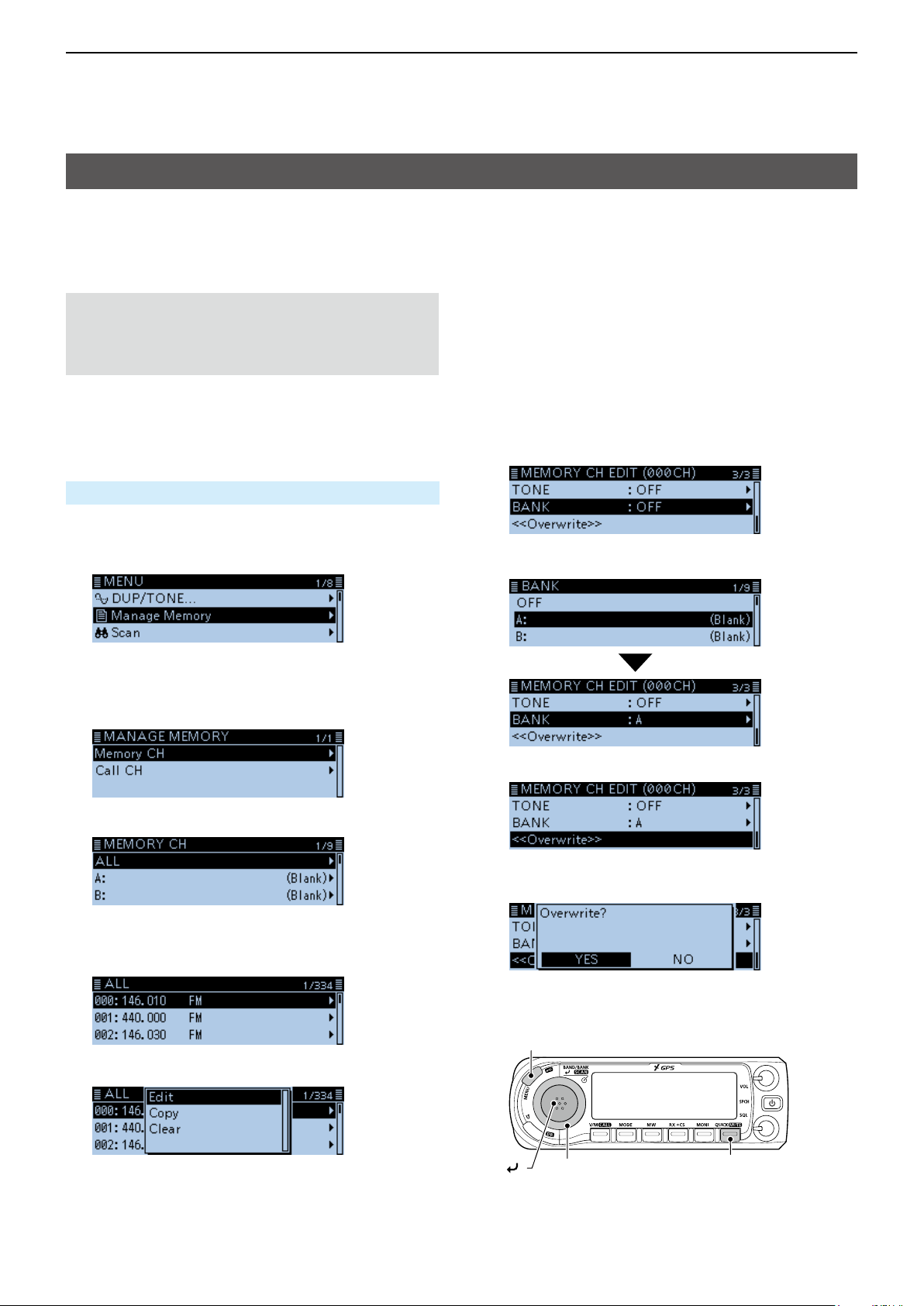
DAssigning a memory channel to a memory bank
Example: Assigning Memory channel “000” to the
bank “A”.
Manage Memory > Memory CH
1. Push [MENU].
2. Rotate [DIAL] to select “Manage Memory,” then
push [ï].
• Displays the MANAGE MEMORY screen.
L You can display the MANAGE MEMORY screen by
pushing [MW] on other than the DR screen.
3. Select “Memory CH,” then push [ï].
4. Select “ALL,” then push [ï].
• Displays the ALL screen.
5. Rotate [DIAL] to select the Memory channel to be
assigned to a bank, then push [QUICK].
7. Select “BANK,” then push [ï].
8. Select a bank to be assigned, then push [ï].
9. Select “<<Overwrite>>,” then push [ï].
• The conrmation dialog “Overwrite?” is displayed.
10. Select <YES>, then push [ï].
• Beeps sound, and assigns the selected memory
channel to the bank.
6. Select “Edit,” then push [ï].
1-8
[MENU]
[ ]
[DIAL]
[QUICK]
Page 16
1
Previous view
MEMORY OPERATION
Memory bank setting (Continued)
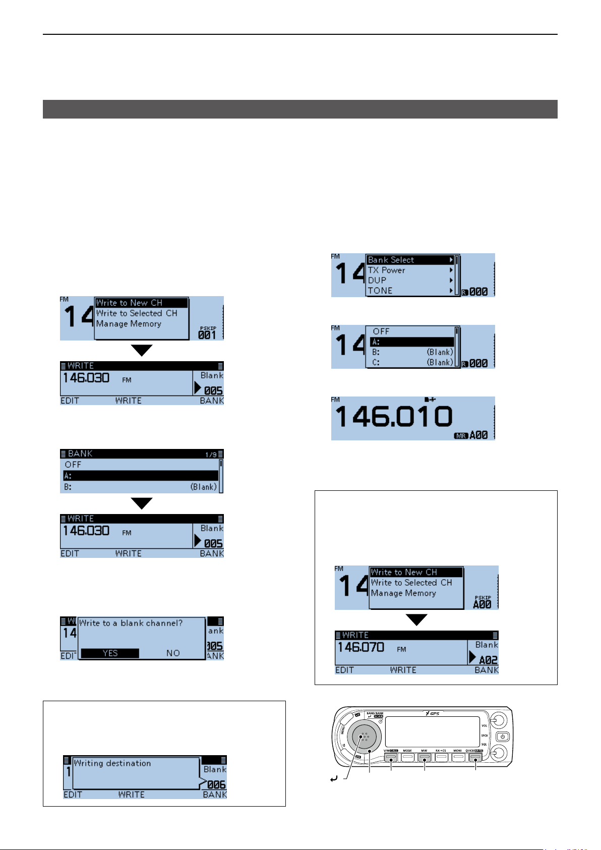
DDirectly writing into a memory bank
You can also write the memory content directly into
a memory bank channel. This way is a short cut to
creating a memory channel, and then assigning it to
a bank. In that case, the transceiver automatically
selects the lowest blank memory channel, to write.
Example: Writing 146.030 MHz into Bank A.
1. Push [V/M] several times until you enter the VFO
mode.
Rotate [DIAL] to set 146.030 MHz.
2.
3.
Push [MW].
4. Rotate [DIAL] to select “Write to New CH,” then
push [ï].
• Displays the WRITE screen.
5. Push [QUICK].
6. Select a bank, then push [ï].
DSelecting the Memory Bank mode
When you select the Memory Bank mode, rotating
[DIAL] selects only the entered bank channels in the
selected bank.
1. Push [V/M] several times until you enter the
Memory mode.
2. Push [QUICK].
3. Rotate [DIAL] to select “Bank Select,” then push
[ï].
4. Select a bank, then push [ï].
5. Rotate [DIAL] to select a bank channel.
L Only assigned bank channels are selectable.
L To return to the Memory mode, select “OFF” in step
4.
7. Push [MW].
• The conrmation dialog “Write to a blank channel?” is
displayed.
8. Select <YES>, then push [ï].
• Beeps sound, and writes the memory content to the
bank channel.
TIP: On the WRITE screen, you can select other
channel by rotating [DIAL].
L If you select a pre-entered channel, the previous
channel content will be overwritten.
TIP: After step 5, you can write the displayed content
to the bank channel.
1. After step 5, push [V/M] to enter the VFO mode.
2. Set the frequency, then push [MW].
3. Rotate [DIAL] to select “Write to New CH,” then
push [ï].
[V/M] [MW] [QUICK]
[DIAL]
[ ]
1-9
Page 17
1
Previous view
MEMORY OPERATION
Entering a Memory or Bank name
You can enter an alphanumeric name for each
Memory, including Call channels, and Banks.
Names can be a maximum of 16 characters.
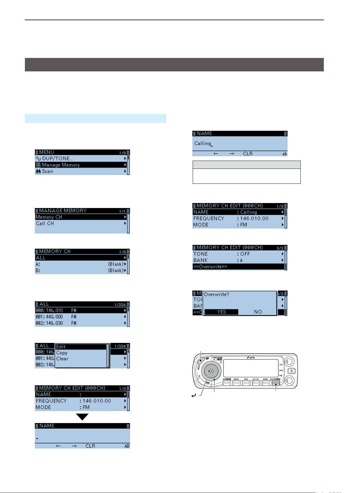
DEntering a Memory name
Manage Memory > Memory CH
1. Push [MENU].
2. Rotate [DIAL] to select “Manage Memory,” then
push [ï].
• Displays the MANAGE MEMORY screen.
L You can display the MANAGE MEMORY screen by
pushing [MW] on other than the DR screen.
3. Select “Memory CH,” then push [ï].
8. Enter a name of up to 16 characters.
(Example: Calling)
Selectable characters and symbols
A to Z, a to z, 0 to 9, ! " # $ % & ’ ( ) * +
, - . / : ; < = > ? @ [ \ ] ^ _ ` { | } ˜ (space)
L See “Entering and editing text” for details. (p. iv)
9. After entering, push [ï].
4. Select “ALL,” then push [ï].
• Displays the ALL screen.
5. Rotate [DIAL] to select the Memory channel to
enter a name, then push [QUICK].
6. Select “Edit,” then push [ï].
7. Select “NAME,” then push [ï].
10. Select “<<Overwrite>>,” then push [ï].
• The conrmation dialog “Overwrite?” is displayed.
11. Select <YES>, then push [ï].
• Beeps sound, and writes the entered name to the
channel.
[MENU]
[ ]
[DIAL]
[QUICK]
• Enters the name entry mode.
1-10
Page 18
1
Previous view
MEMORY OPERATION
Entering a Memory or Bank name (Continued)
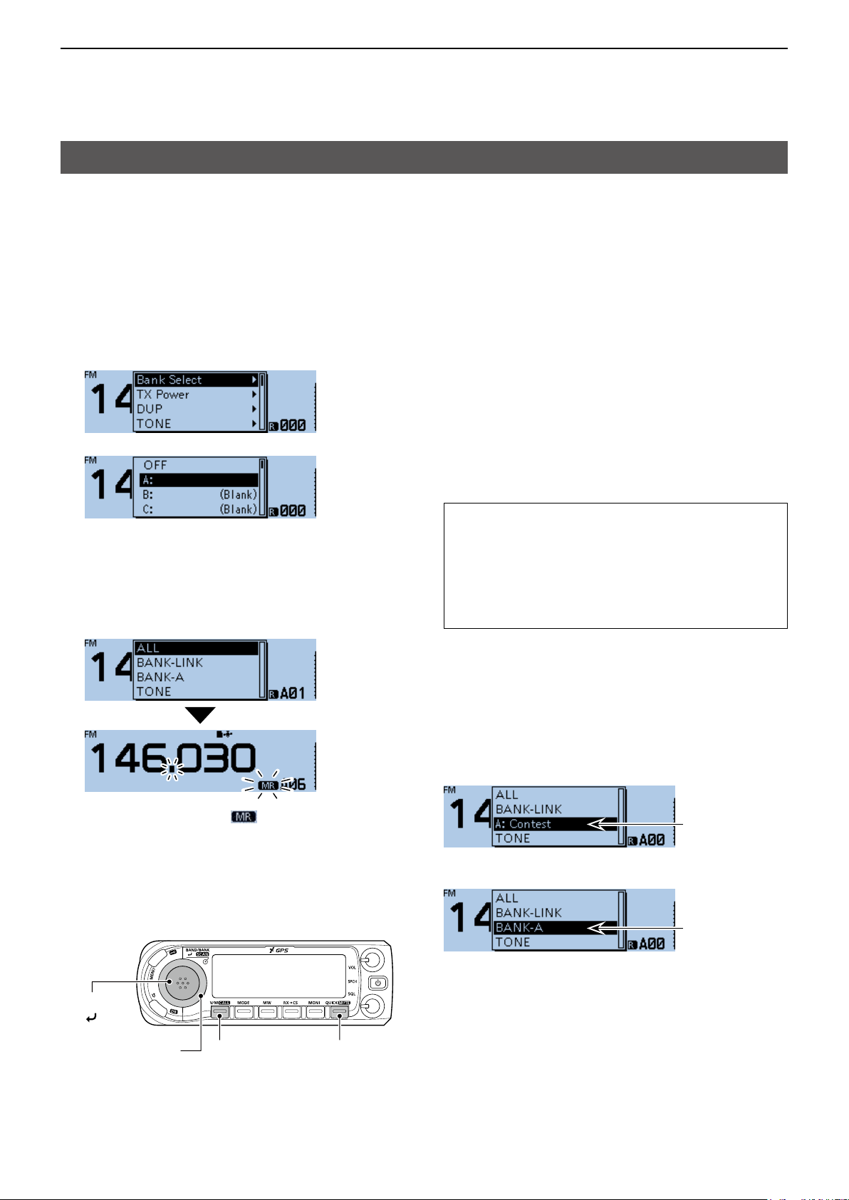
DEntering a Bank name
Manage Memory > Memory CH
1. Push [MENU].
2. Rotate [DIAL] to select “Manage Memory,” then
push [ï].
[MENU]
• Displays the MANAGE MEMORY screen.
L You can display the MANAGE MEMORY screen by
pushing [MW] on other than the DR screen.
3. Select “Memory CH,” then push [ï].
4. Select a bank group to enter a name, then push
[QUICK].
5. Select “Edit Name.”
[ ]
[DIAL]
[QUICK]
6. Enter a bank name of up to 16 characters.
7. After entering, push [ï].
• Enters the bank name entry mode.
(Example: Contest)
Selectable characters and symbols
A to Z, a to z, 0 to 9, ! " # $ % & ’ ( ) * +
, - . / : ; < = > ? @ [ \ ] ^ _ ` { | } ˜ (space)
L See “Entering and editing text” for details. (p. iv)
• Beeps sound, and writes the entered name to the
bank.
1-11
Page 19
1
Previous view
MEMORY OPERATION
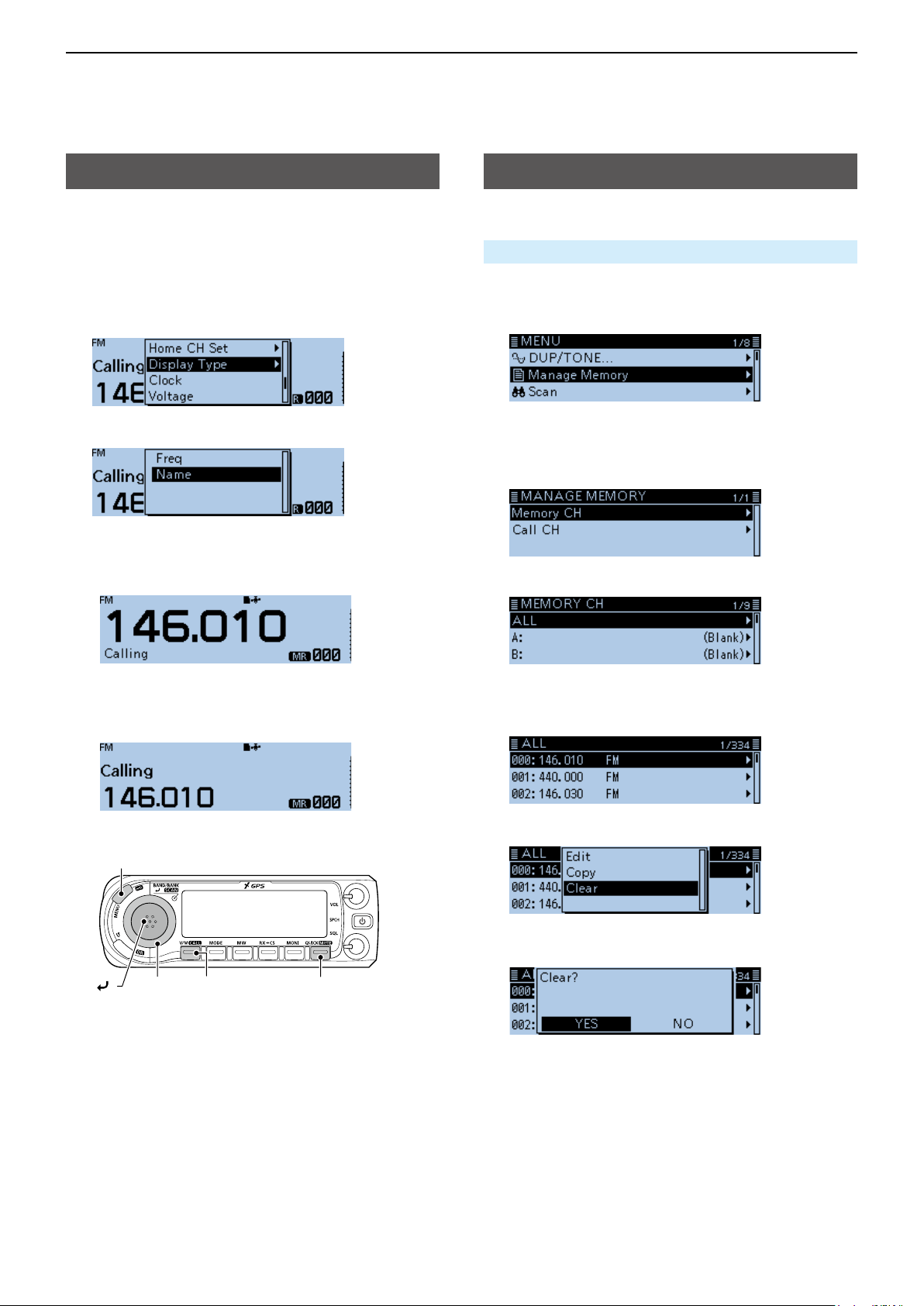
Selecting a Memory name display
The transceiver has two Memory name display types.
1. Push [V/M] several times until you enter the
Memory mode.
2. Push [QUICK].
3. Rotate [DIAL] to select “Display Type,” then push
[ï].
4. Select the display type, then push [ï].
• Freq:
Displays the large font sized frequency and small
font sized memory name.
Clearing a Memory channel
Entered memory content can be cleared.
Manage Memory > Memory CH
1. Push [MENU].
2. Rotate [DIAL] to select “Manage Memory,” then
push [ï].
• Displays the MANAGE MEMORY screen.
L You can display the MANAGE MEMORY screen by
pushing [MW] on other than the DR screen.
3. Select “Memory CH,” then push [ï].
4. Select “ALL,” then push [ï].
• Name:
Displays large font sized memory name and a
small font sized frequency.
[MENU]
[ ]
[DIAL]
[V/M] [QUICK]
• Displays the ALL screen.
5. Rotate [DIAL] to select the Memory channel to be
cleared, then push [QUICK].
6. Select “Clear,” then push [ï].
• The conrmation dialog “Clear?” is displayed.
7. Select <YES>, then push [ï].
• Beeps sound, and clears the memory content.
1-12
Page 20

Section 2 SCAN OPERATION
Previous view
Scan ....................................................................................... 2-2
D About the scan function .................................................. 2-2
D VFO scan ........................................................................ 2-2
D Memory scan .................................................................. 2-2
D Memory bank scan ......................................................... 2-2
D [DIAL] operation during a scan ....................................... 2-3
D Squelch setting for a scan .............................................. 2-3
D Tuning step for a VFO scan ............................................ 2-3
D Skip function ................................................................... 2-3
D Temporary Skip timer ...................................................... 2-3
D Receive mode during a scan .......................................... 2-3
D When a signal is received ............................................... 2-3
D Scan Stop Beep function ................................................ 2-3
VFO mode scan...................................................................... 2-4
D Scan type ........................................................................ 2-4
D About a Scan name ........................................................ 2-5
D About a Program Link name ........................................... 2-5
D Setting the skip frequencies ............................................ 2-5
Memory scan .......................................................................... 2-6
D Scan type ........................................................................ 2-6
Memory Bank scan ................................................................. 2-7
D Scan type ........................................................................ 2-7
D About a Bank name ........................................................ 2-7
Setting and clearing the skip channel ..................................... 2-8
Entering scan edges .............................................................. 2-9
2-1
Page 21
2
Previous view
SCAN OPERATION
Scan
Scanning is a versatile function that can automatically
search for signals. A scan makes it easier to locate
stations to contact or listen to, or to skip unwanted
channels or frequencies.
DAbout the scan function
In the VFO mode
The frequencies that are set as “PSKIP” are skipped
during a scan. (p. 2-5, 9-18)
In the Memory mode
Repeatedly scans all entered Memory channels.
The frequencies that are set as skip channels “PSKIP”
and “SKIP” are not scanned. (p. 2-8)
L Two or more Memory channels must be entered to start a
memory scan.
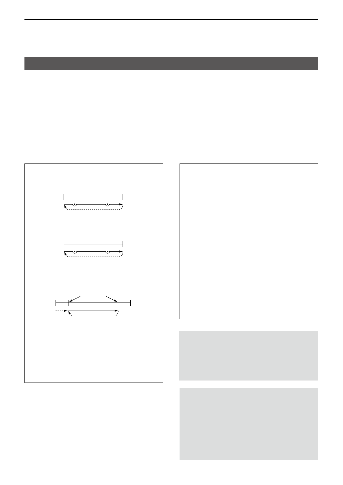
DVFO scan
ALL (Full scan)
Repeatedly scans the entire band.
118 MHz 550 MHz
Scan
P SKIP
Jump
BAND (Selected band scan)
Scans all frequencies over the entire selected band.
Band edge Band edge
Scan
P SKIP
PROG 0 ~ 24 (Program scan)
Scans the Program scan edge ranges.
(Scan > Program Scan Edge) (p. 2-9, 9-18)
Band
edge
Jump
Lower
freq.
Scan edges
L At least one Program scan edge range must be
entered to start a Program scan.
P-LINK0–9 (Program link scan)
Sequentially scans the Program scan edge ranges
which are set to link on the MENU screen.
(p. 9-19)
(Scan > Program Link)
Jump
Scan
Jump
P SKIP
P SKIP
Higher
freq.
Band
edge
DMemory scan
ALL (Memory full scan)
Scans all Memory channels.
BAND (Selected band memory scan)
Scans all Memory channels on the same frequency
band as the selected channel.
MODE (Mode memory scan)
Scans Memory channels which are entered with
the same receiving mode as the currently selected
mode.
DMemory bank scan
ALL (Full bank scan)
Scans all banks.
BANK-LINK (Bank link scan)
Sequentially scans the banks which are set to link
on the MENU screen. (p. 9-18)
(Scan > Bank Link)
BANK-A–Z (Bank scan)
Scans the Memory channels in the selected bank.
Duplex (DUP) scan
The Duplex scan searches for both TX and RX
frequencies which are used in duplex operation.
(p. 8-4)
L “D–” or “D+” is displayed in the Duplex mode.
L A Duplex scan does not start when the frequency
offset is set to “0.000 MHz.”
Tone scan
The Tone scan searches for tone frequencies or
DTCS codes that are used by stations using the
Tone Squelch function.
L A Tone scan is usable in any VFO, Memory, or
Call channel mode.
L During a scan, rotate [DIAL] to change the scan
direction.
See “Tone Squelch function” or “DTCS code
Squelch function” for details. (pp. 10-11, 10-12)
2-2
Page 22

2
Previous view
SCAN OPERATION
Scan (Continued)
D[DIAL] operation during a scan
• Rotate [DIAL] to change the scan direction during a
scan.
• When the scan is paused, rotate [DIAL] to resume
the scan.
DSquelch setting for a scan
You can change the squelch level to suit your
operating needs. Set the squelch level to open the
squelch, according to the received signal strength.
During a scan, rotate [SQL] to adjust the squelch
level.
DTuning step for a VFO scan
The selected tuning step is applied to the scan.
For a Program scan or Program Link scan, set the
tuning step in the Program Scan Edge ranges.
(p. 2-9)
DSkip function
The skip function speeds up scanning by not scanning
those frequencies set as skip channels. (pp. 2-5, 2-8)
TIP: When “Program Skip” is set to OFF, you cannot
use the Scan Skip function. (p. 9-18)
(Scan > Program skip)
DWhen a signal is received
When a signal is received, the scan pauses for
approximately 10 seconds (default), then resumes.
The scan resumes approximately 2 seconds (default)
after the signal disappears.
To manually resume the scan, rotate [DIAL].
L These settings can be changed on the MENU
screen. (p. 9-18)
(Scan > Pause Timer)
(Scan > Resume Timer)
The S-meter displays the
received signal strength.
DScan Stop Beep function
The Scan Stop Beep function sounds a beep when a
signal is received.
This function can be turned ON or OFF on the MENU
screen. (p. 9-66)
(Sounds > Scan Stop Beep)
When receiving a signal
DTemporary Skip timer
The Temporary Skip function temporarily skips
unwanted frequencies during a scan, for the set
period of time.
• These settings can be changed on the MENU
screen. (p. 9-18)
(Scan > Temporary Skip Timer)
DReceive mode during a scan
• The VFO scan uses the selected receive mode.
L For a Program scan or Program Link scan, set the
tuning step in the Program Scan Edge ranges. (p. 2-9)
• During a Memory or Bank scan, the mode entered
into the channel is used.
Scanning in the FM mode
Displays the scan type
Beeps
2-3
Page 23
2
Previous view
SCAN OPERATION
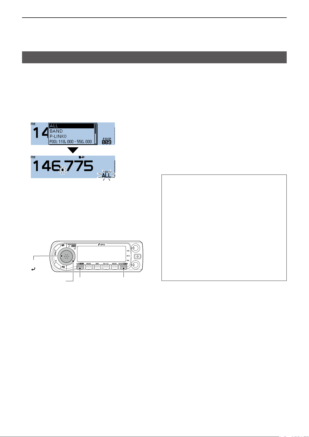
VFO mode scan
1. Push [V/M] several times until you enter the VFO
mode.
2. Hold down [SCAN] for 1 second.
• Opens the Scan Type Select window.
L If you hold down [SCAN] for 3 seconds, the last
selected scan starts.
3. Rotate [DIAL] to select a scan type, then push
[ï].
• The scan starts.
L The decimal point and the selected scan type icon
blink.
L When receiving a signal, the S-meter displays the
received signal strength.
4. Push [SCAN].
• Cancels the scan.
[SCAN]
[ ]*
[DIAL]
[QUICK][V/M]
DScan type
The VFO mode scan has 6 scan types.
• ALL: Full scan
• BAND: Band scan
• P-LINK0 ~ 9: Program link scan
• P00 ~ 24: Program scan
• DUP: Duplex scan
(Displayed only when duplex is set.)
• TONE: Tone scan
(For the Tone Squelch scanning)
L The frequencies that are set as a Skip channel (PSKIP)
are skipped during a scan. (p. 2-8)
L When “Program Skip” is set to “OFF,” the Skip channel
frequencies are not skipped. (p. 9-18)
(Scan > Program Skip)
TIP:
• During a scan, rotating [DIAL] changes the
scanning direction.
• During a scan, you can change the operating
band, scan edge, and so on, in the Quick Menu
window.
• The scan continuously runs, even if you push
[MENU] or [QUICK] during a scan.
• You can set the tuning step and the operating
mode used for a Program scan or Program Link
scan. (p. 2-9)
• The transceiver can receive on the AIR, 144 MHz,
230 MHz, 300 MHz, and 430 MHz bands.*
* Selectable band differs, depending on the transceiver’s
version.
L You can transmit on only the amateur band
frequencies.
*The key operation may differ,
depending on the operating status.
2-4
Page 24
2
Previous view
SCAN OPERATION
VFO mode scan (Continued)
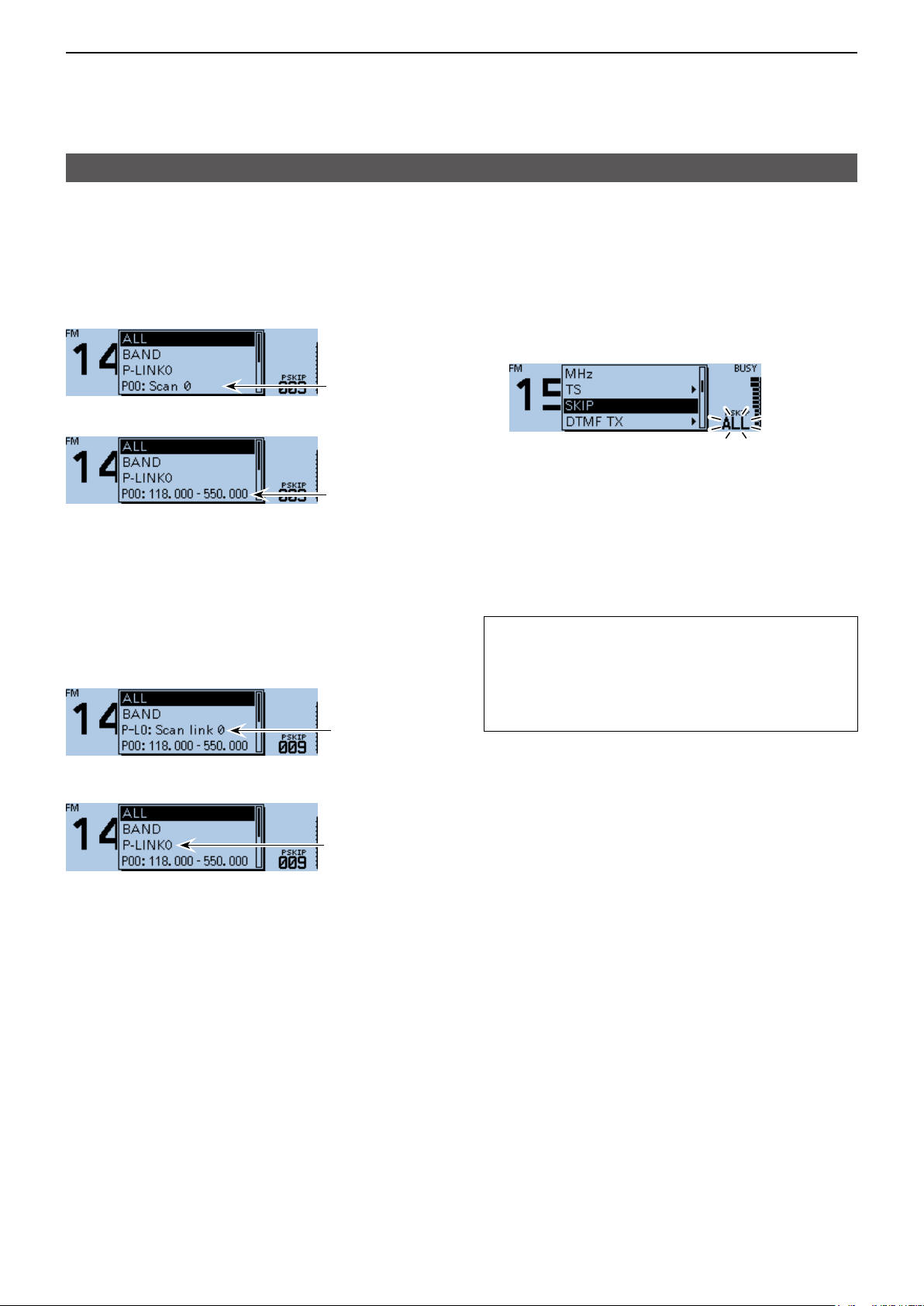
DAbout a Scan name
When a Scan name is assigned, the name is
displayed in the Scan Type Select window. (p. 2-4)
L The Scan name is not displayed during a scan.
L See page 2-9 to enter the scan name.
When the Scan name is assigned
Scan name
When the Scan name is not assigned
Scan edges
DAbout a Program Link name
When a Program Link name is assigned, the name is
displayed in the Scan Type Select window. (p. 2-4)
L The Program Link name is not displayed during a scan.
L See page 2-9 to enter the program link name.
When the Program Link name is assigned
Program
Link name
DSetting the skip frequencies
You can set unnecessary frequencies as Skip
channels (PSKIP) to be skipped during a scan. The
Skip function speeds up a scan.
1. Start the VFO scan.
• When a signal is received, the scan pauses.
2. Push [QUICK].
3. Rotate [DIAL] to select “SKIP.”
• Sets the frequency as a Skip channel into empty
Memory channel 999.
• The entered Memory channel number blinks.
L If channel 999 already has content, the transceiver
automatically searches for another blank channel to
use. If there is no blank channel, a beep sounds, and
the frequency is not set as a Skip channel.
4. After setting, the scan resumes.
TIP: Once frequencies are set as a Skip channel,
these frequencies are skipped until clearing the skip
setting. To clear the skip setting, see page 2-8 for
details.
L The skip setting is also cleared when the Memory
channel set as a Skip channel is cleared. (p. 1-12)
When the Program Link name is not assigned
Program link
2-5
Page 25

2
Previous view
SCAN OPERATION
Memory scan
NOTE: Two or more Memory channels, which are
not set as Skip channels, must be entered to start a
Memory scan.
1. Push [V/M] several times until you enter the
Memory mode.
2. Hold down [SCAN] for 1 second.
• Opens the Scan Type Select window.
L If you hold down [SCAN] for 3 seconds, the last
selected scan starts.
3. Rotate [DIAL] to select a scan type, then push
[ï].
• The scan starts.
L The decimal point and blink.
L When receiving a signal, the S-meter displays the
received signal strength.
4. Push [SCAN].
• Cancels the scan.
DScan type
The Memory mode scan has 5 scan types.
• ALL: Full scan
• BAND: Band Memory scan
• MODE: Mode Memory scan
• DUP: Duplex scan
(Displayed only when duplex is set.)
• TONE: Tone scan
(For the Tone squelch scanning)
L When two or more Memory channels, which are not
set as Skip channels, are entered, the Memory scan is
usable.
L The channels that are set as a Skip channel (PSKIP or
SKIP) are skipped during a scan. (p. 2-8)
TIP:
• During a scan, rotating [DIAL] changes the
scanning direction.
• The scan continuously runs, even if you push
[MENU] or [QUICK] during a scan.
[SCAN]
[ ]*
[DIAL]
*The key operation may differ,
depending on the operating status.
[V/M]
2-6
Page 26
2
Previous view
SCAN OPERATION
Memory Bank scan
A Memory Bank scan searches through the Memory
channels in the selected bank.
L Two or more Memory channels, which are not set as skip
channels, must be entered to start a Memory Bank scan.
(p. 1-8)
1. Push [V/M] several times until you enter the
Memory mode.
2. Push [QUICK].
3. Rotate [DIAL] to select “Bank Select,” then push
[ï].
4. Select a bank to be scanned, then push [ï].
5. Hold down [SCAN] for 1 second.
• Opens the Scan Type Select window.
L If you hold down [SCAN] for 3 seconds, the last
selected scan starts.
6. Rotate [DIAL] to select a scan type, then push
[ï].
• The scan starts.
DScan type
• ALL: Full bank scan
• BANK-LINK: Bank link scan
• BANK-A ~ Z: Bank scan
( Displays only banks which contain a
Memory channel.)
• DUP: Duplex scan
( Displayed only when duplex is set on
the channel.)
• TONE: Tone scan (For tone scanning)
L When all channels are set as “SKIP” or “PSKIP,” the bank
is skipped during a Bank Link scan. (p. 2-8)
L When all channels in the selected bank are set as “SKIP”
or “PSKIP,” the scan does not start.
L When two or more Memory channels, which are not set
as Skip channels, are entered in a bank, the Memory
bank scan is usable. (p. 2-7)
TIP:
• During a scan, rotating [DIAL] changes the
scanning direction.
• The scan continuously runs, even if you push
[MENU] or [QUICK] during a scan.
• During a scan, you can change the bank to be
scanned on the Quick Menu window.
L The decimal point and blink.
L When receiving a signal, the S-meter displays the
received signal strength.
7. Push [SCAN].
• Cancels the scan.
[SCAN]
[ ]*
[DIAL]
*The key operation may differ,
depending on the operating status.
DAbout a Bank name
When a Bank name is assigned, the name is
displayed on the Scan Type Select window.
L The scan name is not displayed during a scan.
L See page 1-11 to enter the Bank name.
When the Bank name is assigned
Bank name
When the Bank name is not assigned
Bank initial
[QUICK][V/M]
2-7
Page 27
2
Previous view
SCAN OPERATION
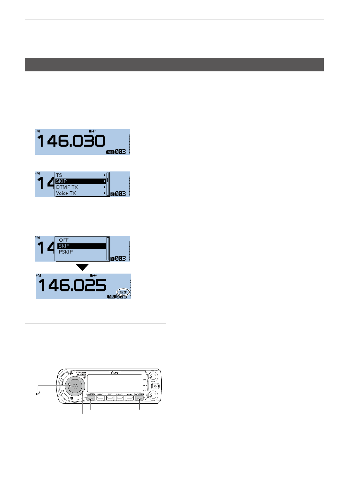
Setting and clearing the skip channel
You can set or clear a Skip channel setting.
The channels that are set as a Skip channel are
skipped during a scan.
1. Push [V/M] several times until you enter the
Memory mode.
2. Rotate [DIAL] to select the Memory channel.
3. Push [QUICK].
4. Rotate [DIAL] to select “SKIP,” then push [ï].
5. Select the option, then push [ï].
• OFF: Cancel the skip setting.
• SKIP: Skipped during a memory scan.
• PSKIP: Skipped during both VFO and memory
scans.
• When a Skip channel is set, “SKIP” or “PSKIP” is
displayed.
TIP: To clear the skip channel setting
To clear the skip channel setting, select “OFF” in
step 5, then push [ï].
[ ]
[DIAL]
[QUICK][V/M]
2-8
Page 28
2
Previous view
SCAN OPERATION
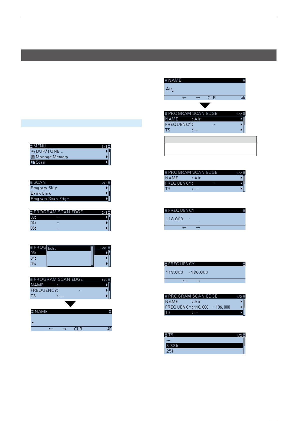
Entering scan edges
You can enter the upper and lower frequency edges to
the Program scan edge ranges for Program scans.
Each Program scan edge range has its own tuning
step and the receive mode.
The default setting is differ, depending on the
transceiver version.
You can enter a total of up to 25 Program scan edge
ranges.
Scan > Program Scan Edge
1. Push [MENU].
2. Rotate [DIAL] to select “Scan,” then push [ï].
• Displays the SCAN screen.
3. Select “Program Scan Edge,” then push [ï].
4. Select a scan edge channel.
8. Enter a name of up to 16 characters, then push
[ï]. (Example: Air)
Selectable characters and symbols
A to Z, a to z, 0 to 9, ! " # $ % & ’ ( ) * +
, - . / : ; < = > ? @ [ \ ] ^ _ ` { | } ˜ (space)
L See “Entering and editing text” for details. (p. iv)
9. Select “FREQUENCY,” then push [ï].
10. Rotate [DIAL] to set a lower frequency, then push
[ï]. (Example: 118000)
5. Push [QUICK].
6. Select “Edit,” then push [ï].
7. Select “NAME,” then push [ï].
• Enter the name entry mode.
L Push [MW] to move the cursor forwards, or push
[MODE] to move the cursor backwards to select a
digit to enter.
11. Set a higher frequency, then push [ï].
(Example: 136000)
12. Select “TS,” then push [ï].
• Displays the selectable tuning step.
13. Select the tuning step to be used during a scan.
L When you select “---,” the tuning step set in the VFO
mode is used during a scan.
☞ Continued on the next page
2-9
Page 29
2
Previous view
SCAN OPERATION
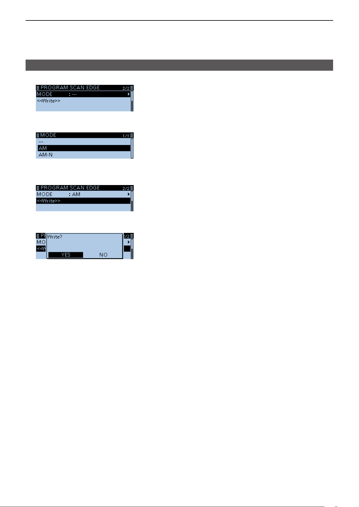
Entering scan edges (Continued)
14. Select “MODE,” then push [ï].
• Displays the selectable mode.
15. Select the receive mode to be used during a scan.
L When you select “---,” the receive mode set in the
VFO mode is used during a scan.
16. Select “<<Write>>,” then push [ï].
• The conrmation dialog “Write?” is displayed.
17. Select <YES>, then push [ï].
• Beeps sound, and automatically writes into the
selected scan edge channel.
• Returns to the PROGRAM SCAN EDGE screen.
2-10
Page 30

Section 3 PRIORITY WATCH
Previous view
Priority watch .......................................................................... 3-2
D Starting the Priority watch ............................................... 3-2
D Canceling the Priority watch ........................................... 3-2
VFO frequency and a Priority channel.................................... 3-3
D When a signal is received ............................................... 3-3
VFO frequency and a Memory/Bank scan.............................. 3-4
D When a signal is received ............................................... 3-4
VFO scan and a Priority channel ............................................ 3-5
D When a signal is received ............................................... 3-5
VFO scan and a Memory/Bank scan ...................................... 3-6
D When a signal is received ............................................... 3-6
Scanning “FROM” on the DR screen and a Priority channel .. 3-7
D When a signal is received ............................................... 3-7
DR scan and a Priority channel .............................................. 3-8
D When a signal is received ............................................... 3-8
3-1
Page 31

3
Previous view
PRIORITY WATCH
Priority watch
While operating on a VFO frequency, using the DR
function or while scanning, Priority watch checks for
signals on a selected frequency every 5 seconds.
DStarting the Priority watch
To start the Priority watch, select “ON” or “Bell,” as
described below.
1. Push [QUICK].
2. Rotate [DIAL] to select “PRIO Watch,” then push
[ï].
3. Select an option, then push [ï].
• ON: Starts Priority Watch.
When a signal is received on the Priority
channel, the channel is automatically
selected.
• Bell: Starts Priority Watch.
When a signal is received on the Priority
channel, the “S” icon blinks.
DCanceling the Priority watch
1. Push [QUICK].
2. Rotate [DIAL] to select “PRIO Watch OFF,” then
push [ï].
• “P” disappears, and the Priority watch is canceled.
• “P” is displayed, and the Priority watch starts.
3-2
Page 32

3
Previous view
PRIORITY WATCH
VFO frequency and a Priority channel
Checks the selected Priority channel every 5 seconds,
while receiving on a VFO frequency.
Step 1. Set the VFO frequency
(See Basic manual section 3)
1. Push [V/M] several times until you enter the VFO
mode.
2. Set the receive frequency and mode you want to
monitor.
Step 2. Set the Priority channel
To select a Memory channel (p. 1-4)
1. Push [V/M] to enter the Memory mode.
2. Rotate [DIAL] to select the Memory channel you
want to monitor.
To select a Bank channel (p. 1-9)
1. Push [V/M] to enter the Memory mode.
2. Push [QUICK].
3. Rotate [DIAL] to select “Bank Select,” then push [ï].
4. Rotate [DIAL] to select the Bank channel you want
to monitor.
To select a Call channel (p. 1-4)
1. Hold down [CALL] for 1 second to enter the Call
channel mode.
2. Rotate [DIAL] to select the Call channel you want
to monitor.
Step 3. Starts the Priority watch (p. 3-2)
1. Push [QUICK].
2. Rotate [DIAL] to select “PRIO Watch,” then push
[ï].
3. Select the Priority watch option, then push [ï].
• “P” is displayed, and the Priority watch starts.
VFO
frequency
Receiving
(5 seconds)
Priority
channel
Step 4. Canceling the Priority watch (p. 3-2)
1. Push [QUICK].
2. Rotate [DIAL] to select “PRIO Watch OFF,” then
push [ï].
• “P” disappears, and the Priority watch is canceled.
DWhen a signal is received
When “ON” is selected.
When a signal is received on the Priority channel, the
channel is automatically selected.
• The “P” icon blinks.
L The scan pause timer and resume settings are the same
as those for a normal scan. (p. 9-18)
Automatically selects
the Priority channel.
When “Bell” is selected.
When a signal is received on the Priority channel, the
display remains in the VFO mode.
• A beep sounds and the “S” icon blinks.
Remains in the VFO mode.
Example:
Checks Memory channel “002” while
receiving on 146.010 MHz.
Priority channel
Checks Memory channel “002”
every 5 seconds.
3-3
Page 33

3
Previous view
PRIORITY WATCH
VFO frequency and a Memory/Bank scan
Sequentially checks the Memory or Bank channels
every 5 seconds, while receiving on a VFO frequency.
Step 1. Set the VFO frequency
(See Basic manual section 3)
1. Push [V/M] several times until you enter the VFO
mode.
2. Set the receive frequency and mode you want to
monitor.
Step 2. Start a Memory or Bank scan
To start a Memory scan (p. 2-6)
1. Push [V/M] to enter the Memory mode.
2. Hold down [SCAN] for 1 second.
• Opens the Scan Type Select window.
3. Rotate [DIAL] to select a scan type, then push
[ï].
• The scan starts.
To start a Bank scan (p. 2-7)
1. Push [V/M] to enter the Memory mode.
2. Push [QUICK].
3. Rotate [DIAL] to select “Bank Select,” then push [ï].
4. Select a bank to be scanned, then push [ï].
5. Hold down [SCAN] for 1 second.
• Opens the Scan Type Select window.
6. Rotate [DIAL] to select a scan type, then push
[ï].
• The scan starts.
Step 3. Starts the Priority watch (p. 3-2)
1. Push [QUICK].
2. Rotate [DIAL] to select “PRIO Watch,” then push [ï].
3. Select the Priority watch option, then push [ï].
• “P” is displayed, and the Priority watch starts.
Example:
Sequentially checks the Memory channels
while receiving on 146.010 MHz.
VFO
mode
Receiving
(5 seconds)
When using a
Memory scan
SKIP
0
1
2
999
M-CH
VFO
mode
Receiving
(5 seconds)
When using a
Bank scan
SKIP
00
01
02
99
Bank CH
Step 4. Canceling the Priority watch (p. 3-2)
1. Push [QUICK].
2. Rotate [DIAL] to select “PRIO Watch OFF,” then
push [ï].
• “P” disappears, and the Priority watch is canceled.
L The Memory or Bank scan is also canceled.
DWhen a signal is received
When “ON” is selected.
When a signal is received on the Priority channel, the
channel is automatically selected.
• The “P” icon blinks.
L The scan pause timer and resume settings are the same
as those for a normal scan. (p. 9-18)
Automatically selects
the Priority channel.
When “Bell” is selected.
When a signal is received on the Priority channel, the
display remains in the VFO mode.
• A beep sounds and the “S” icon blinks.
Remains in the VFO mode.
The Memory channels
are sequentially checked.
Checks the Memory channels every 5 seconds.
3-4
Page 34

3
Previous view
PRIORITY WATCH
VFO scan and a Priority channel
Checks the selected Priority channel every 5 seconds,
during a VFO mode scan.
VFO
mode
Scan
(5 seconds)
Priority
channel
Step 1. Set the Priority channel
To select a Memory channel (p. 1-4)
1. Push [V/M] to enter the Memory mode.
2. Rotate [DIAL] to select the Memory channel you
want to monitor.
To select a Bank channel (p. 1-9)
1. Push [V/M] to enter the Memory mode.
2. Push [QUICK].
3. Rotate [DIAL] to select “Bank Select,” then push
[ï].
4. Rotate [DIAL] to select the Bank channel you want
to monitor.
To select a Call channel (p. 1-4)
1. Hold down [CALL] for 1 second to enter the Call
channel mode.
2. Rotate [DIAL] to select the Call channel you want
to monitor.
Step 2. Starts the Priority watch (p. 3-2)
1. Push [QUICK].
2. Rotate [DIAL] to select “PRIO Watch,” then push [ï].
3. Select the Priority watch option, then push [ï].
• “P” is displayed, and the Priority watch starts.
Step 3. Starts the VFO scan (p. 2-4)
1. In the VFO mode, hold down [SCAN] for 1 second.
• Opens the Scan Type Select window.
2. Rotate [DIAL] to select a scan type, then push
[ï].
• The scan starts.
Step 4. Canceling the Priority watch (p. 3-2)
1. Push [QUICK].
2. Rotate [DIAL] to select “PRIO Watch OFF,” then
push [ï].
• “P” disappears, and the Priority watch is canceled.
DWhen a signal is received
When “ON” is selected.
When a signal is received on the Priority channel, the
channel is automatically selected.
• The “P” icon blinks.
L The scan pause timer and resume settings are the same
as those for a normal scan. (p. 9-18)
Automatically selects the Priority channel.
When “Bell” is selected.
When a signal is received on the Priority channel, the
display remains in the VFO mode.
• A beep sounds and the “S” icon blinks.
Remains in the VFO mode.
Example: Checks
Memory channel “002” during a VFO
mode scan.
Checks Memory channel “002”
every 5 seconds.
3-5
Page 35

3
Previous view
PRIORITY WATCH
VFO scan and a Memory/Bank scan
Sequentially checks the
Memory or Bank
channels
every 5 seconds during a VFO mode scan.
A Memory scan or Bank scan can be selected.
Step 1. Start a Memory or Bank scan
To start a Memory scan (p. 2-6)
1. Push [V/M] to enter the Memory mode.
2. Hold down [SCAN] for 1 second.
• Opens the Scan Type Select window.
3. Rotate [DIAL] to select a scan type, then push
[ï].
• The scan starts.
To start a Bank scan (p. 2-7)
1. Push [V/M] to enter the Memory mode.
2. Push [QUICK].
3. Rotate [DIAL] to select “Bank Select,” then push [ï].
4. Select a bank to be scanned, then push [ï].
5. Hold down [SCAN] for 1 second.
• Opens the Scan Type Select window.
6. Rotate [DIAL] to select a scan type, then push [ï].
• The scan starts.
SKIP
00
01
02
99
Bank CH
0
SKIP
VFO
mode
Scan
(5 seconds)
When using VFO scan
and a Memory scan
1
2
999
M-CH
VFO
mode
Scan
(5 seconds)
When using VFO scan
and a Bank scan
Step 4. Canceling the Priority watch (p. 3-2)
1. Push [QUICK].
2. Rotate [DIAL] to select “PRIO Watch OFF,” then
push [ï].
• “P” disappears, and the Priority watch is canceled.
DWhen a signal is received
When “ON” is selected.
When a signal is received on the Priority channel, the
channel is automatically selected.
• The “P” icon blinks.
L The scan pause timer and resume settings are the same
as those for a normal scan. (p. 9-18)
Step 2. Starts the Priority watch (p. 3-2)
1. Push [QUICK].
2. Rotate [DIAL] to select “PRIO Watch,” then push [ï].
3. Select the Priority watch option, then push [ï].
• “P” is displayed, and the Priority watch starts.
Step 3. Starts the VFO scan (p. 2-4)
1. In the VFO mode, hold down [SCAN] for 1 second.
• Opens the Scan Type Select window.
2. Rotate [DIAL] to select a scan type, then push
[ï].
• The scan starts.
Example:
Sequentially checks the Memory channels
while
VFO scanning.
Automatically selects the Priority channel.
When “Bell” is selected.
When a signal is received on the Priority channel, the
display remains in the VFO mode.
• A beep sounds and the “S” icon blinks.
Remains in the VFO mode.
Sequentially checks the Memory
channels every 5 seconds.
3-6
Page 36

3
Previous view
PRIORITY WATCH
Scanning “FROM” on the DR screen and a Priority channel
Checks the selected Priority channel every 5 seconds,
while receiving a repeater or simplex frequency in
“FROM” of the DR screen.
Step 1. Set the Priority channel
To set the VFO frequency
(See Basic manual section 3)
1. Push [V/M] several times until you enter the VFO
mode.
2. Set the receive frequency and mode you want to
monitor.
To select a Memory channel (p. 1-4)
1. Push [V/M] several times until you enter the
Memory mode.
2. Rotate [DIAL] to select the Memory channel you
want to monitor.
To select a Bank channel (p. 1-9)
1. Push [V/M] several times until you enter the
Memory mode.
2. Push [QUICK].
3. Rotate [DIAL] to select “Bank Select,” then push
[ï].
4. Rotate [DIAL] to select the Bank channel you want
to monitor.
To select a Call channel (p. 1-4)
1. Hold down [CALL] for 1 second to enter the Call
channel mode.
2. Rotate [DIAL] to select the Call channel you want
to monitor.
Step 2. Select the repeater or simplex frequency in
the DR screen (p. 4-3, D-STAR guide)
1. Hold down [DR] for 1 second to display the DR
screen.
2. Select “FROM,” then push [ï].
• Displays the FROM SELECT screen.
L On the DR screen, pushing [DR] toggles between
“FROM” and “TO.”
3. Rotate [DIAL] to select a repeater or a simplex
frequency.
“From”
(DR screen)
Receiving
(5 seconds)
Example: Checks
Priority
channel
(Frequency/
Channel)
Memory channel “002”
every 5
seconds while receiving on a repeater
frequency.
Checks Memory channel “002”
every 5 seconds.
Step 4. Canceling the Priority watch (p. 3-2)
1. Push [QUICK].
2. Rotate [DIAL] to select “PRIO Watch OFF,” then
push [ï].
• “P” disappears, and the Priority watch is canceled.
DWhen a signal is received
When “ON” is selected.
When a signal is received on the Priority channel, the
channel is automatically selected.
• The “P” icon blinks.
L The scan pause timer and resume settings are the same
as those for a normal scan. (p. 9-18)
Automatically selects the Priority channel.
Step 3. Starts the Priority watch (p. 3-2)
1. Push [QUICK].
2. Rotate [DIAL] to select “PRIO Watch,” then push [ï].
3. Select the Priority watch option, then push [ï].
• “P” is displayed, and the Priority watch starts.
When “Bell” is selected.
When a signal is received on the Priority channel, the
display remains on the DR screen.
• A beep sounds and the “S” icon blinks.
Remains on the DR screen.
3-7
Page 37

3
Previous view
PRIORITY WATCH
DR scan and a Priority channel
Checks the selected Priority channel every 5 seconds,
during a DR scan.
Step 1. Set the Priority channel
To set the VFO frequency
(See Basic manual section 3)
1. Push [V/M] several times until you enter the VFO
mode.
2. Set the receive frequency and mode you want to
monitor.
To select a Memory channel (p. 1-4)
1. Push [V/M] several times until you enter the
Memory mode.
2. Rotate [DIAL] to select the Memory channel you
want to monitor.
To select a Bank channel (p. 1-9)
1. Push [V/M] several times until you enter the
Memory mode.
2. Push [QUICK].
3. Rotate [DIAL] to select “Bank Select,” then push
[ï].
4. Rotate [DIAL] to select the Bank channel you want
to monitor.
To select a Call channel (p. 1-4)
1. Hold down [CALL] for 1 second to enter the Call
channel mode.
2. Rotate [DIAL] to select the Call channel you want
to monitor.
DR
scan
Scan
(5 seconds)
Example: Checks
Priority
channel
Memory channel “002”
every 5
seconds during a DR scan.
Checks Memory channel “002”
every 5 seconds.
Step 4. Canceling the Priority watch (p. 3-2)
1. Push [QUICK].
2. Rotate [DIAL] to select “PRIO Watch OFF,” then
push [ï].
• “P” disappears, and the Priority watch is canceled.
Step 2. Start the DR scan (p. 4-5)
1. Hold down [DR] for 1 second to display the DR
screen.
2. Hold down [SCAN] for 1 second.
• Displays the DR scan setting window.
3. Rotate [DIAL] to select the scan type, then push
[ï].
• The selected scan starts.
Step 3. Starts the Priority watch (p. 3-2)
1. Push [QUICK].
2. Rotate [DIAL] to select “PRIO Watch,” then push [ï].
3. Select the Priority watch option, then push [ï].
• “P” is displayed, and the Priority watch starts.
DWhen a signal is received
When “ON” is selected.
When a signal is received on the Priority channel, the
channel is automatically selected.
• The “P” icon blinks.
L The scan pause timer and resume settings are the same
as those for a normal scan. (p. 9-18)
Automatically selects the Priority channel.
When “Bell” is selected.
When a signal is received on the Priority channel, the
display remains on the DR screen.
• A beep sounds and the “S” icon blinks.
Remains on the DR screen.
3-8
Page 38

Section 4 D-STAR OPERATION
Previous view
“FROM” (Access repeater) setting.......................................... 4-3
D Using your transceiver’s repeater list .............................. 4-4
D Using the DR scan .......................................................... 4-5
D Using the Near Repeater Search function ...................... 4-6
D Using the TX History ....................................................... 4-7
“TO” (Destination) setting ....................................................... 4-8
D Using the “Local CQ” (Local Area call) ........................... 4-9
D Using the “Gateway CQ” (Gateway call) ......................... 4-9
D Using “Your Call Sign” ................................................... 4-10
D Using the RX History .................................................... 4-10
D Using the TX History ......................................................4-11
D Directly entering (UR) ....................................................4-11
D Directly entering (RPT) ................................................. 4-12
Connecting to a Reector ..................................................... 4-13
D What is the reector? .................................................... 4-13
D Using a reector ............................................................ 4-13
D Linking to a reector ..................................................... 4-14
D Unlinking a reector ...................................................... 4-15
D Reector Echo Testing .................................................. 4-15
D Requesting repeater information .................................. 4-16
Message operation ............................................................... 4-17
D Entering a TX message ................................................ 4-17
D Transmitting a message ................................................ 4-17
D TX message deleting .................................................... 4-18
Viewing the received call signs ............................................ 4-19
D View the call signs in the RX History screen................. 4-19
BK mode communication...................................................... 4-21
EMR communication ............................................................ 4-22
D Adjusting the EMR AF level .......................................... 4-22
Automatic DV detection ........................................................ 4-23
Automatic Reply function ...................................................... 4-24
D Recording an Auto Reply message .............................. 4-25
D Auto Position Reply function ......................................... 4-26
Data communication ............................................................. 4-27
D Connection .................................................................... 4-27
D Data communication application setting ....................... 4-27
D Sending data ................................................................. 4-27
D DV Fast Data function ................................................... 4-28
Digital squelch functions ....................................................... 4-29
D The digital call sign squelch setting .............................. 4-29
D Digital call sign squelch function with a Pocket beep ... 4-29
D The digital code squelch setting ................................... 4-30
D Digital code squelch function with a Pocket beep ......... 4-30
Viewing call signs ................................................................. 4-31
Repeater list ......................................................................... 4-32
D Repeater list contents ................................................... 4-32
Entering new information into the Repeater List................... 4-33
D Required items for the communication cases ............... 4-33
D Entering new information into the repeater list ............. 4-34
Editing a repeater list ............................................................ 4-37
Deleting a repeater list.......................................................... 4-37
Rearranging the display order of the repeater ...................... 4-38
Adding the Repeater information using the RX History
........ 4-39
☞ Continued on the next page
4-1
Page 39

(Continued)
Previous view
Skip setting for the DR scan ................................................. 4-40
D Individual skip setting .................................................... 4-40
D Group skip setting ......................................................... 4-40
Entering the repeater group name........................................ 4-41
Repeater detail screen ......................................................... 4-42
Entering Your (destination) call sign ..................................... 4-43
Deleting Your (destination) call sign ..................................... 4-44
Rearranging the display order of Your (destination) call signs
. 4-45
Your setting is correct? ......................................................... 4-46
IMPORTANT!
• The repeater list, described in this manual, may differ from your transceiver’s preloaded contents.
• Although Japanese repeaters are used in the setting examples, the Japanese repeater node (port) letters are
different from other country’s.
Be sure to add the repeater node letter in the 8th digit of the call sign, according to the frequency band shown
below.
1200 MHz : A (B in Japan)
430 MHz : B (A in Japan)
144 MHz : C (no D-STAR repeaters in Japan)
To begin digital mode communication using other than the D-STAR Repeater (DR) function
To begin the digital mode communication using other
than the DR function, you can use the VFO mode,
Memory mode or Call channel mode.
This manual description focuses on the DR function
operation which can be set up easily. If you want to
use other than the DR function, see the procedures
For a Local area call or Gateway call:
1. Set the access repeater’s frequency. (p. 8-2)
2. Set the Duplex direction. (p. 8-4)
3. Set the frequency offset for the Duplex operation.
(p. 8 -4)
4. Set the call signs (UR/R1/R2). (p. 9-41)
as described to the right, or select the repeater in a
memory channel.
For a Simplex call:
1.
Set the operating frequency.
2. Set the UR call sign (for call sign squelch).
(p. 9 -41)
4-2
Page 40

4
Previous view
D-STAR OPERATION
“FROM” (Access repeater) setting
Your access repeater must be set in “FROM” when
you make a call on the DR screen.
You have ve ways to set the access repeater.
Setting by [DIAL]
Select the preset repeater by rotating [DIAL] on the DR screen.
• When you know your access repeater
From the repeater list (p. 4-4)
You can select your access repeater from the repeater list by
selecting the repeater area and name, if entered, or call sign.
Displayed
while rotating
[DIAL]
• When you do not know which repeater you can access.
Search for a repeater using the DR scan (p. 4-5)
The Normal DR scan searches for output repeater frequencies of
nearby repeaters. The scan will stop when a signal is detected.
• The scan will also stop on simplex signals.
The Near Repeater scan searches for output repeater frequencies of nearby repeaters that are within 160
kilometer (99.4 miles) from your location and the repeater’s location that is entered in the Repeater List. The
DR scan starts scanning and will stop when a signal is detected.
You can also nd only FM repeaters using the Near Repeater (FM) scan.
Search for near repeaters (p. 4-6)
Searches for near repeaters that are within 160 kilometer
(99.4 miles) from your location using your GPS location and the
repeater’s location that is entered in the Repeater List.
The nearest repeaters in your transceiver’s Repeater List are
displayed as selectable choices.
You can select the nearby DV only, FM only, or both repeater types.
• When the “FROM” data is saved in the TX History.
Setting from the TX History (p. 4-7)
Select a repeater that you have accessed before from the TX
History record.
Scan items
4-3
Page 41

4
Previous view
D-STAR OPERATION
“FROM” (Access repeater) setting (Continued)
DUsing your transceiver’s repeater list
When your access repeater is in your transceiver’s
repeater list, you can select it from the list. By only
selecting the repeater from the list, the call sign,
frequency, duplex and offset frequency settings are
automatically set for easy operation.
Example: Selecting the “Hirano” repeater in Japan
from the repeater list.
1. Hold down [DR] for 1 second to display the DR
screen.
2. Select “FROM,” then push [ï].
• Displays the FROM SELECT screen.
L On the DR screen, pushing [DR] toggles between
“FROM” and “TO.”
3. Rotate [DIAL] to select “Repeater List,” then push
[ï].
• Displays the REPEATER GROUP screen.
4. Select the repeater group where your access
repeater is listed, then push [ï].
(Example: “11: Japan”)
5. Select your access repeater, then push [ï].
(Example: “Hirano”)
• Returns to the DR screen, and the selected repeater
name is displayed in “FROM.”
L The repeater list, described in this manual, may
differ from your transceiver’s preloaded contents.
TIP:
When you select an FM repeater:
When an FM repeater is in your transceiver’s
repeater list, you can select it from the list.
When selecting an FM repeater, the “TO” setting is
not necessary and a “---” is displayed in “TO.”
When selecting an FM repeater.
(Sample)
How to change the repeater group:
To change the repeater
group on the DR screen,
push [QUICK], then select
“Group Select.”
4-4
Page 42

4
Previous view
D-STAR OPERATION
“FROM” (Access repeater) setting (Continued)
DUsing the DR scan
The DR scan scans frequencies to nd a signal on a
repeater or a simplex frequency.
You can use two kinds of DR scans, Normal scan and
Near Repeater scan.
Normal scan
To quickly nd a repeater, the Normal scan skips
repeaters that are not specied as an access repeater.
(The “USE (FROM)” setting is set to “NO” (SKIP is
set) on the repeater list.)
Near Repeater scan
The Near Repeater scan searches for up to 20 nearby
repeaters by using your location and the repeater’s
entered location, and then lists the repeaters.
L The Near Repeater scan will continue, even if you
turn OFF the power, and then turn it ON again
during the scan.
L If your own position is not being received, the last
received position is used.
NOTE: Even if your transceiver receives a repeater
signal, the repeater may not receive your signal,
because the repeater’s output power is higher than
your transceiver’s, and your signal doesn't reach the
repeater.
TIP: The DR scan scans the simplex frequencies in
the repeater list, in addition to a D-STAR repeaters.
Example: Selecting the “HamFair” repeater in Japan
using the DR scan.
1. Hold down [DR] for 1 second to display the DR
screen.
2.
Hold down [SCAN] for 1 second.
• Displays the DR scan setting window.
DR scan
setting window
3. Rotate [DIAL] to select the scan type.
• Normal:
Searches for repeaters whose “USE (FROM)”
setting is set to “YES.”
• Near Repeater (ALL):
Searches for up to 20 nearby DV or FM
repeaters. (Total 40 repeaters)
• Near Repeater (DV):
Searches for up to 20 nearby DV repeaters.
• Near Repeater (FM):
Searches for up to 20 nearby FM repeaters.
4. Push [ï].
• The selected scan starts.
The repeaters
are sequentially
While DR scanning
L While DR scanning, the repeaters are sequentially
displayed.
L The scan resumes the same as other scans.
(p. 9-18)
displayed.
5. When the transceiver receives a signal from a
repeater, the scan stops.
6. Push [SCAN].
• The DR scan is canceled, and the repeater is set to
“FROM.”
4-5
Page 43

4
Previous view
D-STAR OPERATION
“FROM” (Access repeater) setting (Continued)
DUsing the Near Repeater Search function
The transceiver searches for the nearest repeater
by using your location and the repeater’s entered
position.
The nearest repeater in your transceiver’s repeater list
is displayed as the available choices.
NOTE:
• When using the Repeater Search function, be sure
to rst receive your own position data, or manually
enter your position data.
• If no repeater is found within a 160 kilometer range,
“No Repeater Found” will be displayed.
• If the last received position can be used, “GPS
is invalid. Search by last valid position” will be
displayed.
Example: Selecting the “Icom Repeater” in Japan
from the Near Repeater list.
Step 2: Selecting the access repeater from the
Near Repeater list
1. Hold down [DR] for 1 second to display the DR
screen.
2. Select “FROM,” then push [ï].
• Displays the FROM SELECT screen.
L On the DR screen, pushing [DR] toggles between
“FROM” and “TO.”
3. Select “Near Repeater,” then push [ï].
• Displays the NEAR REPEATER screen.
4. Select the type of nearby repeater to display, then
push [ï].
Step 1: Receiving your own position from the GPS
satellite
L When it is difcult to receive signals indoors, even
if you are near a window, try going outdoors for
better reception.
Conrm the GPS receiver is receiving your position.
• The GPS icon blinks when searching for satellites.
➪ ➪ ➪
• The GPS icon stops blinking when the minimum needed
number of satellites is found.
L It may take only a few seconds to receive, or it may take
a few minutes, depending on your operating environment.
L If your own position is not being received, the last
received position is used.
• Near Repeater (ALL):
Displays up to 20 nearby DV and FM repeaters.
(A total 40 repeaters)
• Near Repeater (DV):
Displays up to 20 nearby DV repeaters.
• Near Repeater (FM):
Displays up to 20 nearby FM repeaters.
5. Select the repeater to select it as your access
repeater, considering the distance from your
position to the repeater, then push [ï].
(Example: “Icom Repeater”)
Repeater
call sign.
Displayed for
FM repeaters
• Returns to the DR screen, and the selected repeater is
set in “FROM.”
* When the position data accuracy level is set to
“Approximate,” the direction data is not displayed if the
distance to the repeater is less than 5 kilometers.
(p. 4-36)
Distance and direction
from your position to
the repeater*
4-6
Page 44

4
Previous view
D-STAR OPERATION
“FROM” (Access repeater) setting (Continued)
DUsing the TX History
Repeaters you transmitted on before are saved in
the TX History. You can select a repeater from the TX
History as your access repeater.
The TX History saves up to 10 of the latest “FROM”
(Access) repeaters.
Example: Selecting the “Hirano” repeater in Japan
from the TX History.
1. Hold down [DR] for 1 second to display the DR
screen.
2. Select “FROM,” then push [ï].
• Displays the FROM SELECT screen.
L On the DR screen, pushing [DR] toggles between
“FROM” and “TO.”
3. Rotate [DIAL] to select “TX History,” then push
[ï].
• Displays the TX HISTORY screen.
4. Select the TX history, then push [ï].
• TX History (DV): Displays the TX history of the
DV repeaters.
• TX History (FM): Displays the TX history of the
FM repeaters.
5. Select the repeater to use as your access
repeater, then push [ï]. (Example: “Hirano”)
• Returns to the DR screen, and the selected repeater is
set in “FROM.”
TIP: When you push [QUICK]
in step 5, you can display
the REPEATER DETAIL
screen, or delete the repeater
information from the TX
HISTORY screen.
4-7
Page 45

4
Previous view
D-STAR OPERATION
“TO” (Destination) setting
The destination repeater or station must be set in “TO”
when you make a call in the DV mode.
You have eight ways to set the destination.
Setting by rotating [DIAL]
Rotate [DIAL] to select the repeater or Your Call
Sign that is displayed on the DR screen. (This
operation is disabled when “CQCQCQ” is set.)
To make a Local Area CQ call
“Local CQ” setting (p. 4-9)
Set “CQCQCQ” in “TO” (Destination).
To make a Gateway CQ call
“Gateway CQ” setting (p. 4-9)
Select a repeater from the repeater list, if you want
to make a Gateway call.
To make a call to a specic station
“Your Call Sign” setting (p. 4-10)
Select the station call sign in the Your Call Sign
memory.
To make a call through a reector
TIP: After you receive the individual station or
repeater’s signal, the call sign can be captured by
holding down the Call Sign Capture key ([RX→CS]),
and you can quickly and easily reply to a call.
TO SELECT screen
TIP: How to change the
repeater group:
When “Local CQ” or “Gateway
CQ” is selected, you can change
the repeater group.
To change the repeater group on
the DR screen, push [QUICK],
then select “Group Select.”
“Reector” setting (p. 4-12)
Select a reector you want to call through.
To select from RX History
Setting from RX History (p. 4-10)
When you receive a call, the repeater or caller
station data is saved in RX History.
You can select the destination from the record.
To select from TX History
Setting from TX History (p. 4-11)
When you make a call, the destination repeater or
called station data is saved in TX History.
You can select the destination from the record.
To directly enter the destination station call sign
Direct Input (UR) (p. 4-11)
Directly enter the destination station’s call sign.
To directly enter the destination repeater call sign
Direct Input (RPT) (p. 4-12)
Directly enter the destination repeater’s call sign.
4-8
Page 46

4
Previous view
D-STAR OPERATION
“TO” (Destination) setting (Continued)
DUsing the “Local CQ” (Local Area call)
When “Local CQ” is selected on the TO SELECT
screen, “CQCQCQ” is set in “TO.”
Example: Making a Local area call by accessing the
“Hirano” repeater.
1. Hold down [DR] for 1 second to display the DR
screen.
2. Select “TO,” then push [ï].
• Displays the TO SELECT screen.
L On the DR screen, pushing [DR] toggles between
“FROM” and “TO.”
3. Select “Local CQ,” then push [ï].
• Returns to the DR screen, and “CQCQCQ” is
displayed in “TO.”
DUsing the “Gateway CQ” (Gateway call)
When “Gateway CQ” is selected on the TO SELECT
screen, you can select the repeater to make a
gateway call on the repeater list.
Example: Making a Gateway CQ call to the
“Hamacho” (Japan) repeater from the
“Hirano” repeater.
1. Hold down [DR] for 1 second to display the DR
screen.
2. Select “TO,” then push [ï].
• Displays the TO SELECT screen.
L On the DR screen, pushing [DR] toggles between
“FROM” and “TO.”
3. Select “Gateway CQ,” then push [ï].
• Displays the REPEATER GROUP screen.
4. Select the repeater group where your destination
repeater is listed, then push [ï].
(Example: “11: Japan”)
5. Select the destination repeater, then push [ï].
(Example: “Hamacho”)
• Returns to the DR screen, and “Hamacho” is displayed
in “TO.”
TIP: After selecting a destination repeater, you can
select another repeater preset in your repeater list
by rotating [DIAL].
4-9
Page 47

4
Previous view
D-STAR OPERATION
“TO” (Destination) setting (Continued)
DUsing “Your Call Sign”
The “Your Call Sign” memory saves the “UR”
(destination) call signs. When you select an individual
station call sign for the “TO” (Destination) setting using
“Your Call Sign,” you can make a Gateway call. When
you call the destination through a gateway, the signal
is automatically sent to the last repeater that the
station accessed. So, even if you do not know where
the station is, you can make a call.
NOTE: If the repeater, set in “FROM” (Access
Repeater) has no Gateway call sign, you cannot
make a gateway call.
Example: Selecting “Station1” from the “Your Call
Sign.”
1. Hold down [DR] for 1 second to display the DR
screen.
2. Select “TO,” then push [ï].
• Displays the TO SELECT screen.
L On the DR screen, pushing [DR] toggles between
“FROM” and “TO.”
3. Select “Your Call Sign,” then push [ï].
DUsing the RX History
When a call is received in the DV mode, the call data
is saved in the RX History.
Up to 50 Callers, and only the last Called call signs
can be saved.
Example: Selecting “Station1” in the RX History.
1. Hold down [DR] for 1 second to display the DR
screen.
2. Select “TO,” then push [ï].
• Displays the TO SELECT screen.
L On the DR screen, pushing [DR] toggles between
“FROM” and “TO.”
3. Select “RX History,” then push [ï].
• Displays the RX HISTORY screen.
4. Select the destination name or call sign, then
push [ï]. (Example: Station1)
• Displays the YOUR CALL SIGN screen.
4. Select the destination name or call sign, then
push [ï]. (Example: Station1)
• Returns to the DR screen, and “Station1” is displayed
in “TO.”
TIP: After selecting a destination, you can select
another station preset in your transceiver by rotating
[DIAL].
• Returns to the DR screen, and “Station1” is displayed
in “TO.”
TIP: To add the RX HISTORY data to memory, push
[QUICK], then select “Add To Your Memory.”
4-10
Page 48

4
Previous view
D-STAR OPERATION
“TO” (Destination) setting (Continued)
DUsing the TX History
The TX History saves the name and/or call sign of up
to 20 “TO” (Destination) settings that were used when
you made the calls.
NOTE: Until you make a call in the DV mode, you
cannot select “TO” (destination) from the TX History.
Example:
1. Hold down [DR] for 1 second to display the DR
2. Select “TO,” then push [ï].
3. Select “TX History,” then push [ï].
Selecting the “Hamacho” repeater in the TX
History.
screen.
• Displays the TO SELECT screen.
L On the DR screen, pushing [DR] toggles between
“FROM” and “TO.”
DDirectly entering (UR)
The destination station call sign can be directly
entered.
Example: Directly entering the call sign “JM1ZLK.”
1. Hold down [DR] for 1 second to display the DR
screen.
2. Select “TO,” then push [ï].
• Displays the TO SELECT screen.
L On the DR screen, pushing [DR] toggles between
“FROM” and “TO.”
3. Select “Direct Input (UR),” then push [ï].
• Displays the DIRECT INPUT (UR) screen.
4. Enter a call sign of up to 8 characters, including
spaces.
• Displays the TX HISTORY screen.
4. Select the destination name or call sign, then
push [ï]. (Example: “Hamacho”)
The Sub
name is
displayed.
• Returns to the DR screen, and “Hamacho” is displayed
in “TO.”
TIP: You can add the TX HISTORY data to memory,
or delete it from the TX HISTORY screen, push
[QUICK], then select the option.
L See “Entering and editing text” for details. (p. iv)
5. After entering, push [ï].
• Returns to the DR screen, and “JM1ZLK” is displayed
in “TO.”
L After entry, you can correct the call sign in the
DIRECT INPUT (UR) screen.
L The entered call sign remains on the DIRECT INPUT
(UR) screen, until you enter a new call sign.
TIP: If the entered call sign is duplicated in “Your
Call Sign” memory, the name is displayed. (Only
when the name has been entered.)
4-11
Page 49

4
Previous view
D-STAR OPERATION
“TO” (Destination) setting (Continued)
DDirectly entering (RPT)
The destination repeater call sign can be directly
entered.
Example: Directly entering the call sign “JP1YIU”
1. Hold down [DR] for 1 second to display the DR
screen.
2. Select “TO,” then push [ï].
• Displays the TO SELECT screen.
L On the DR screen, pushing [DR] toggles between
“FROM” and “TO.”
3. Select “Direct Input (RPT),” then push [ï].
• Displays the DIRECT INPUT (RPT) screen.
4. Enter a call sign of up to 8 characters, including
spaces.
L See “Entering and editing text” for details. (p. iv)
5. After entering, push [ï].
• Returns to the DR screen, and “JP1YIU” is displayed
in “TO.”
L After entry, you can correct the call sign in the
DIRECT INPUT (RPT) screen.
L The entered call sign remains on the DIRECT INPUT
(RPT) screen, until you enter a new call sign.
TIP:
• If the entered call sign is duplicated in the repeater
list, the name is displayed. (Only when the name
has been entered.)
• When “/” is entered, the repeater call sign can be
used for a Gateway call.
“/” is entered.
4-12
Page 50

4
Previous view
D-STAR OPERATION
Connecting to a Reector
DWhat is the reector?
A reector is a special server connected to the
Internet and running a version of dplus software. If the
dplus software is installed on your access repeater,
it provides various functions including gateway
and reector linking capabilities (It is known as the
D-STAR reector system). The D-STAR reector
system enables a number of D-STAR repeaters
anywhere to link to a reector. This means that when
you transmit through a D-STAR repeater linked to a
reector, your voice can be heard on other repeaters
linked to the reector, and you can hear other stations
that are connected to the reector.
D-STAR reector system
Access repeater
INTERNET
INTERNET
INTERNET
Reector
INTERNET
USA
DUsing a reector
1. Hold down [DR] for 1 second to display the DR
screen.
2. Select “TO,” then push [ï].
• Displays the TO SELECT screen.
L On the DR screen, pushing [DR] toggles between
“FROM” and “TO.”
3. Rotate [DIAL] to select “Reflector,” then push [ï].
• Displays the REFLECTOR screen.
CAN
UK
AUS
4. Select “Use Reector,” then push [ï].
• Returns to the DR screen, and “Use Reector” and
“CQCQCQ” are displayed in “TO.”
5. Hold down [PTT] to transmit.
• Displays while transmitting.
4-13
Page 51

4
Previous view
D-STAR OPERATION
Connecting to a Reector (Continued)
DLinking to a reector
If your repeater is not currently linked to a reector, or
you want to change to another reector, you can do so
following the steps below. Before linking to a reector,
be sure to unlink any current reector. (p. 4-15)
Direct entering a reector
Example: Directly entering “REF010BL.”
1. Hold down [DR] for 1 second to display the DR
screen.
2. Select “TO,” then push [ï].
• Displays the TO SELECT screen.
L On the DR screen, pushing [DR] toggles between
“FROM” and “TO.”
3. Rotate [DIAL] to select “Reflector,” then push [ï].
• Displays the REFLECTOR screen.
4. Select “Link to Reector,” then push [ï].
• Displays the “Link to Reector” screen.
5. Select “Direct Input,” then push [ï].
6. Rotate [DIAL] to select the reector number.
(Example: 010)
7. Push [MW](→) to move the cursor to the right box.
8. Rotate [DIAL] to select the module letter.
(Example: B)
Using the TX History
The TX History saves the up to 5 reectors that your
access repeater linked before.
Example: Selecting the “REF010BL” in the TX History.
1. Hold down [DR] for 1 second to display the DR
screen.
2. Select “TO,” then push [ï].
• Displays the TO SELECT screen.
L On the DR screen, pushing [DR] toggles between
“FROM” and “TO.”
3. Rotate [DIAL] to select “Reflector,” then push [ï].
• Displays the REFLECTOR screen.
4. Select “Link to Reector,” then push [ï].
• Displays the “Link to Reector” screen.
5. Select the reector that you want to link to.
(Example: “REF010BL”)
• Returns to the DR screen, and “Link to Reector” and
“REF010BL” are displayed in “TO.”
6. Hold down [PTT] to link to the reflector.
• Displays while transmitting.
9. Push [ï].
• Returns to the DR screen, and “Link to Reector” and
“REF010BL” are displayed in “TO.”
10. Hold down [PTT] to link to the reflector.
• Displays while transmitting.
4-14
Page 52

4
Previous view
D-STAR OPERATION
Connecting to a Reector (Continued)
DUnlinking a reector
Before trying to link to another reector, be sure to
unlink the current connected reector.
1. Hold down [DR] for 1 second to display the DR
screen.
2. Select “TO,” then push [ï].
• Displays the TO SELECT screen.
L On the DR screen, pushing [DR] toggles between
“FROM” and “TO.”
3. Rotate [DIAL] to select “Reflector,” then push [ï].
• Displays the REFLECTOR screen.
4. Select “Unlink Reector,” then push [ï].
• Returns to the DR screen, and “Unlink Reector” and
“U” are displayed in “TO.”
5. Hold down [PTT] to unlink the reector.
• Displays while transmitting.
DReector Echo Testing
You can transmit a short message, and after releasing
[PTT], your message will be played back. It is a
useful check of how well your signal is getting into
the repeater, and you can use it to verify that your
repeater is operating normally.
1. Hold down [DR] for 1 second to display the DR
screen.
2. Select “TO,” then push [ï].
• Displays the TO SELECT screen.
L On the DR screen, pushing [DR] toggles between
“FROM” and “TO.”
3. Rotate [DIAL] to select “Reflector,” then push [ï].
• Displays the REFLECTOR screen.
4. Select “Echo Test,” then push [ï].
• Returns to the DR screen, and “Echo Test” and “E” are
displayed in “TO.”
5. Hold down [PTT] and speak into the microphone.
• Displays while transmitting.
6. Release [PTT] to hear your message.
4-15
Page 53

4
Previous view
D-STAR OPERATION
Connecting to a Reector (Continued)
D Requesting repeater information
When you send the repeater information command,
an ID message is sent back.
1. Hold down [DR] for 1 second to display the DR
screen.
2. Select “TO,” then push [ï].
• Displays the TO SELECT screen.
L On the DR screen, pushing [DR] toggles between
“FROM” and “TO.”
3. Rotate [DIAL] to select “Reflector,” then push [ï].
• Displays the REFLECTOR screen.
4. Select “Repeater Information,” then push [ï].
• Returns to the DR screen, and “Repeater Information”
and “I” are displayed in “TO.”
5. Hold down [PTT] to send the repeater information
command.
• Displays while transmitting.
6. Release [PTT] to hear the repeater ID message.
4-16
Page 54

4
Previous view
D-STAR OPERATION
Message operation
You can save up to 5 short messages in memory, to
transmit in the DV mode.
Each message can be up to 20 characters long.
DEntering a TX message
Example: Entering “JAPAN TOM” into message
memory number 1.
My Station > TX Message
1. Push [MENU].
2. Rotate [DIAL] to select “My Station,” then push
[ï].
3. Select “TX Message,” then push [ï].
• Displays the TX MESSAGE screen.
4. Select a message memory number, then push
[QUICK].
5. Select “Edit,” then push [ï].
• Enters the TX Message entry mode.
6. Enter a message of up to 20 characters.
(Example: JAPAN TOM)
Selectable characters and symbols
A to Z, a to z, 0 to 9, ! " # $ % & ’ ( ) * +
, - . / : ; < = > ? @ [ \ ] ^ _ ` { | } ˜ (space)
L See “Entering and editing text” for details. (p. iv)
7. After entering, push [ï].
• Returns to the TX MESSAGE screen.
DTransmitting a message
You can transmit a pre-entered text message by
pushing [PTT]. First, select a TX message which also
turns ON the Message Transmission function.
My Station > TX Message
1. Push [MENU].
2. Rotate [DIAL] to select “My Station,” then push
[ï].
3. Select “TX Message,” then push [ï].
• Displays the TX MESSAGE screen.
4. Select a message memory, then push [ï].
(Example: 1: JAPAN TOM)
L To not transmit any message, select “OFF.”
5. Push [MENU].
• Returns to the standby screen.”
InformationL
• The message is transmitted each time you push
[PTT].
• The message is transmitted along with your voice
signal.
TIP: RX call sign and message display
As the default, the received call sign and message
are automatically displayed and scrolled on the LCD.
To not display and scroll them, set “RX Call Sign” to
“OFF.”
(Display > RX Call Sign)
8. Push [MENU].
Scrolls
• Returns to the standby screen.”
4-17
Page 55

4
Previous view
D-STAR OPERATION
Message operation (Continued)
DDeleting a TX message
You can delete the entered TX message.
Example: Deleting the entered TX message “JAPAN
TOM” from message memory number 1.
My Station > TX Message
1. Push [MENU].
2. Rotate [DIAL] to select “My Station,” then push
[ï].
3. Select “TX Message,” then push [ï].
• Displays the TX MESSAGE screen.
4. Select a message memory number to delete, then
push [QUICK].
5. Select “Clear,” then push [ï].
• The conrmation dialog “Clear?” is displayed.
6. Select <YES>, then push [ï].
• Clears the entered message.
7. Push [MENU].
• Returns to the standby screen.”
4-18
Page 56

4
Previous view
D-STAR OPERATION
Viewing the received call signs
When you receive a DV call, the calling station and
the repeater’s call signs are saved. Up to 50 calls can
be saved. Even if the transceiver is turned OFF, the
RX record is not deleted. When you receive the 51th
call, the oldest history will be deleted.
D View the call signs in the RX History screen
1. Push [QUICK].
2. Rotate [DIAL] to select “RX History,” then push
[ï].
• Displays the RX HISTORY screen.
3. Rotate [DIAL] to select an RX history memory.
InformationL
• The RX history number, the caller’s name (or call
sign), destination, RX message, RX date and time,
“GW,” and “GPS” are displayed on the screen.
• “GW” is displayed when the Gateway call is received.
• “GPS” is displayed when the received call includes the
position data.
• “UP” is displayed when the repeater uplink signal is
received.
• Hold down [RX→CS] for 1 second to temporary set
the received call sign to the “TO” eld (destination).
4. Push [ï].
• Displays the RX history detail screen.
RX HISTORY screen (RX01)
Displayed when a
Gateway call is received.
D-PRS TX
format icon*
First
page
Called station
( “CQCQCQ” is
displayed if you
received a CQ call.)
1
History
number
Caller station*
L A note may be
displayed after “/”.
Received
date and time
2
RX message
5. Rotate [DIAL].
• Selects the page.
<First page>
• CALLER: Displays the caller station’s name*2
and any note entered after the call
sign.
• CALLED: Displays the called station
’s name*2.
<Second page>
• RXRPT1: Displays the repeater
’s name*2 that
was accessed by the caller station. If
it was a call through a gateway and
the internet, this item displays the
gateway call sign of the repeater you
received the call from.
• Rx RPT2: Displays the repeater
’s name*2 you
received the call from.
L “FREQUENCY” is displayed instead of above
items when the call was not through a repeater
(Simplex call), to show the frequency that was
used.
<Third page>
• RX MESSAGE: Displays any message included in
the received call, if entered.
• RX TIME: Displays the date and time the
call was received.
1
*
The displayed icon differs, depending on the D-PRS TX
format.
GPS: Position OBJ: Object
ITEM: Item WX: Weather
2
*
When a name is not entered in the memory, call sign
is displayed. You can change the display type between
“Name Display” and “Call Sign Display” in the Quick menu
window. (Default: Name Display)
☞ Continued on the next page
4-19
Page 57

4
Previous view
D-STAR OPERATION
Viewing the received call signs
D View the call signs in the RX History screen (Continued)
<Fourth page>, <Fifth page>, <Sixth page>
Displays the position data of the caller station. If a
received signal has no data, then no position data
is displayed.
6. Push [MENU].
• Returns to the standby screen.
TIP: To delete the RX HISTORY data
On the RX HISTORY or the detail screen, push
[QUICK], then select “Delete.”
TIP: “RX RPT1” setting may differ, depending on the way the call was made.
Example: When a Local area call is received. Example: When a Gateway call is received.
JG3LUK calling
to JM1ZLK on
JP3YHH port A...
CALLED
RX RPT2
RX RPT1
GW
INTERNETINTERNET
JG3LUK calling to
JM1ZLK on
JP3YHH port A...
YOUR STATION
JG3LUK calling to
JM1ZLK on
JP3YHH port A...
CALLER
CALLED
JG3LUK calling
to JM1ZLK on
JP3YHH port A...
JG3LUK calling
to JM1ZLK on
JP3YHH port A...
RX RPT1RX RPT2
JG3LUK calling
to JM1ZLK on
JP3YHH port A...
CALLER
YOUR STATION
4-20
Page 58

4
Previous view
D-STAR OPERATION
BK mode communication
The BK (Break-in) function enables you to break
into a conversation, where the two other stations
are communicating with call sign squelch enabled.
(Default: OFF)
L The BK function is automatically turned OFF when
transceiver is turned OFF.
DV Set > BK
1. While two other stations are communicating in the
DV mode, hold down [RX→CS] for 1 second.
• The calling station’s call sign is set to “TO”
(Destination).
L When a call sign is not received correctly, error
beeps sound, and no call sign is set.
L After releasing, beeps sound and the calling station’s
call sign is announced. (RX→CS Speech function)
2. Push [MENU].
3. Rotate [DIAL] to select “DV Set,” then push [ï].
4. Select “BK,” then push [ï].
5. Select “ON,” then push [ï].
6. Push [MENU].
• Returns to the standby screen, and “BK” is displayed.
7. When both stations are in standby, push [PTT] to
transmit.
• Displays while transmitting.
L “BK” blinks when receiving the Break-in call.
L To cancel the BK mode, select “OFF” in step 5, or
turn OFF the transceiver.
How to use Break-in?
While using digital call sign squelch, the squelch never opens (no audio is heard) even if a call is received, unless
your own call sign is specied.
However, when a call including the “BK ON” signal (break-in call) is received, the squelch will open and audio is
heard even if the call is specied for another station.
Station C calling to Station A with “BK OFF”
Station A
and B are
communicating
using digital
call sign
squelch.
Station A Station B
Station C
Station B never hears that
Station C is calling Station A.
Station C calling to Station A with “BK ON”
Station A
and B are
communicating
using digital
call sign
squelch.
Station A Station B
Station C
Station B also hears that
Station C is calling Station A.
4-21
Page 59

4
Previous view
D-STAR OPERATION
EMR communication
The EMR (Enhanced Monitor Request)
communication function can be used in only the DV
mode. Using the EMR function, no call sign setting is
necessary.
All transceivers that receive an EMR signal
automatically open their squelch to receive the signal.
When an EMR signal is received, the audio (voice)
will be heard at the specied level, even if the volume
setting level is set to the minimum level, or the digital
call sign/digital code squelch is used. (Default: OFF)
L The EMR communication function is automatically
turned OFF when the transceiver is turned OFF.
Example: Transmitting from the “Hirano” repeater
using the EMR function.
DV Set > EMR
1. Push [MENU].
2. Rotate [DIAL] to select “DV Set,” then push [ï].
3. Select “EMR,” then push [ï].
DAdjusting the EMR AF level
The audio output level when an EMR signal is
received is adjustable between 0 and 32.
When an EMR signal is received, the audio will be
heard at the preset level, or the [VOL] control level,
whichever is higher.
To disable the setting, set it to “0.”
DV Set > EMR AF Level
1. Push [MENU].
2. Rotate [DIAL] to select “DV Set,” then push [ï].
3. Select “EMR AF Level,” then push [ï].
4. Rotate [DIAL] to adjust the EMR audio output level
between 0 (minimum) and 32 (maximum) in single
digit steps. (Default: 19)
5. Push [MENU].
• Returns to the standby screen.
4. Select “ON,” then push [ï].
5. Push [MENU].
• Returns to the standby screen, and “EMR” is
displayed.
6. Push [PTT] to transmit.
• Displays while transmitting.
L “EMR” blinks on a station that receives the EMR
signal. The audio (voice) will be heard at the
specied level, or the [VOL] control level, whichever
is higher.
L To cancel the EMR mode, select “OFF” in step 4, or
turn OFF the transceiver.
4-224-22
Page 60

4
Previous view
D-STAR OPERATION
Automatic DV detection
If you receive an FM signal while in the DV mode, the
“DV” and “FM” icons alternately blink to indicate the
received signal is FM.
When the DV Auto Detect function is turned ON, the
transceiver automatically selects the FM mode to
temporarily monitor the signal. (Default: OFF)
L Regardless of this setting, the “DV” and “FM” icons
alternately blink if you receive an FM signal while in
the DV mode.
TIP: When digital call sign squelch (DSQL) or digital
code squelch (CSQL) is set, the transceiver does not
receive FM signals, even if this function is ON. You
can silently wait for calls from others.
DV Set > DV Auto Detect
1. Push [MENU].
2. Rotate [DIAL] to select “DV Set,” then push [ï].
3. Select “DV Auto Detect,” then push [ï].
4. Select “ON,” then push [ï].
5. Push [MENU].
• Returns to the standby screen.
L When an FM signal is received while in the DV
mode, the “DV” and “FM” icons sequentially blink,
and the transceiver receives the signal in the FM
mode.
When an FM signal is received while in the DV mode
DV Auto Detect function: OFF
The “DV” and “FM” icons alternately blink, but the
audio cannot be heard.
These icons
alternately blink
• • •
The audio
cannot be heard.
DV Auto Detect function: ON
The “DV” and “FM” icons alternately blink, and the
audio can be heard.
These icons
alternately blink
Thanks for the
nice QSO• • •
The audio
can be heard.
4-23
Page 61

4
Previous view
D-STAR OPERATION
Automatic Reply function
When a call addressed to your own call sign is
received, the Automatic Reply function automatically
replies with your call sign. (Default: OFF)
Depending on the setting, a recorded message may
be transmitted with the call sign.
NOTE: The Automatic Reply function temporary sets
the received call sign to the destination call sign.
TIP: To record the Auto Reply message
You can record the Auto Reply message. See page
9-22 for details.
(Voice Memo > DV Auto Reply)
DV Set > Auto Reply
Push [MENU].
1.
2. Rotate [DIAL] to select “DV Set,” then push [ï].
3.
Select “Auto Reply,” then push [ï].
4. Select an option.
• ON: Automatically replies with your own call
sign. (No audio reply is sent)
• Voice: Automatically replies with your call
sign and an Auto Reply message
recorded on the microSD card (up to 10
seconds).
L If no card is inserted, or no message is
recorded, replies with your own call sign.
(No audio reply is sent)
• Position: Automatically replies with your own call
sign and your position data using the
internal or external GPS receiver.
L When “GPS Select” is set to “OFF” or
“Manual,” the internal GPS receiver is
temporarily turned ON.
When “GPS Select” is set to “External
GPS,” but if the external GPS receiver is
not connected, the internal GPS receiver
is temporarily turned ON.
5. Push [MENU].
• Returns to the standby screen, and displays “ .”
L When “ON” or “Voice” is selected, the Automatic
Reply function is automatically turned OFF, when you
push [PTT].
When “Position” is selected, the Automatic Reply
function remains ON, when you push [PTT].
Example: After receiving a call from “JM1ZLK,” the
transceiver automatically sends a reply call.
The “TO” setting does not change, but “UR:
JM1ZLK (Caller’s call sign)” is displayed.
4-24
Page 62

4
Previous view
D-STAR OPERATION
Automatic Reply function (Continued)
D Recording an Auto Reply message
You can record the Auto Reply message and saved on
a microSD card to reply to the call with your voice.
TIP: Be sure a microSD card is in the card slot.
Voice Memo > DV Auto Reply
1. Push [MENU].
2. Rotate [DIAL] to select “Voice Memo,” then push
[ï].
3. Select “DV Auto Reply,” then push [ï].
4. Push [MW].
• Starts recording.
DV AUTO REPLY screen operation
[MENU]
Returns to the standby screen
[ ]
Sets
[ ]
Returns to the
VOICE MEMO
screen
[V/M]
Selects the
microphone
[MODE]
Adjusts the
microphone gain
[MW]
Starts recording
[MONI]
Stops recording
[RX→CS]
Starts the playback
[QUICK]
Clears the
recorded message
L Maximum record time is 10 second
L Hold the microphone 5 to 10 cm (2 to 4 inches) from
your mouth, then speak at a normal voice level.
L Only one message can be recorded. The current
contents will be overwritten if you record again.
5. Push [MENU].
• Returns to the standby screen.
TIP:
• To delete the recorded message, push [QUICK] on
the DV AUTO REPLY screen, then select “Clear.”
• To record message with the optional VS-3
Bluetooth headset, push [V/M] on the DV AUTO
REPLY screen, then select “Bluetooth MIC.”
• Push [MONI] to stop recording.
• Push [RX→CS] to start the playback.
• Push [MODE] to display the microphone gain
adjustment bar.
Audio level
is displayed
Adjust the Mic gain so
that the REC Level does
not reach to this range
4-254-25
Page 63

4
Previous view
D-STAR OPERATION
Automatic Reply function (Continued)
DAuto Position Reply function
When you receive a call addressed to your own call
sign, but are in a situation that makes it difcult to
operate the transceiver, this function automatically
replies with your own call sign and transmits your
position data.
After receiving the Auto Position Reply call, the
position
data is displayed in a window.
L Only the Icom transceivers, ID-4100A/E, ID-
5100A/E, ID-51A/E PLUS, or ID-51A/E PLUS2,
displays the position after receiving a call. (As of
April 2017)
L You can turn OFF the caller’s position indication.
(Display > RX Position Display) (p. 9-63)
caller’s
2. Your position data is
automatically transmitted.
1. A call addressed to
Your station
3. After receiving,
the position data
is displayed in the
destination’s window.
your own call sign.
Destination
(ID-4100A/E)
When no valid position data is received
After receiving a call addressed to your own call sign,
the internal GPS receiver is temporarily turned ON for
approximately 5 minutes to receive your position data,
even if “GPS Select” is set to “OFF,” “External GPS,”
or “Manual.” Then, the transceiver automatically
replies with a message, as described below.
L When the internal GPS receiver is temporarily ON, and
valid position data is received, the transceiver transmits
your position data if a call addressed to your own call
sign is received again.
Reply message list when no valid position data is
received
Message Status
No Position When no position is received.
2 minutes or more has
Old Position
passed since receiving
position data.
The internal GPS receiver is
No Posi & GPS Start
temporarily turned ON, but
has not received your position
data yet.
The internal GPS receiver is
temporarily turned ON, and 2
Old Posi & GPS Start
minutes or more have passed
since receiving the position
data.
Scrolls your call sign or the TX
message.
L Your status message may be
displayed.
Scrolls your message
TIP:
• The position data is transmitted according to the
GPS TX mode. (p. 9-24)
• When the GPS TX mode settings are incorrect
for the Automatic Reply function, the transceiver
automatically corrects them to reply to a call.
• When the GPS transmission mode is OFF,
“D-PRS” is automatically selected.
4-264-26
Page 64

4
Previous view
D-STAR OPERATION
Data communication
In addition to digital voice communication, you can
send and receive data. And you can use the DV Fast
Data function for data communication.
The DV Fast Data function uses the data and the
audio frames to send data approximately 3.5 times
faster than the normal speed. So, no audio can be
sent. To send and receive data, the optional OPC2350LU and a data communication software (user
supplied) are required.
NOTE: Before staring data communication
“DV Data TX” is set to “Auto” as the default setting.
So, when you enter text data into your
communication software, the transceiver may
automatically transmit it, depending on the software
and the software settings.
DConnection
Connect the transceiver to your PC using the optional
OPC-2350LU, as shown below.
Transceiver
PC
To the
[DATA] jack
To the
USB port
DSending data
1. Set your own call sign, the UR call sign and the
repeater call sign.
2. Follow the instructions of your data
communication application software.
3. When you enter text data into your communication
software, the transceiver may automatically
transmit it, depending on the software and the
software settings.
L When “DV Data TX” is set to “PTT,” pushing [PTT]
transmits the text data and a voice signal. (p. 9-48)
(DV Set > DV Data TX)
L Before transmission, the transceiver sends
approximately 500 milliseconds of carrier sense.
NOTE:
• Only the ASCII code can be used for data
communication.
• The standard Message Transmission function also
transmits up to 20 characters. (pp. 4-17, 4-18)
• Depending on the combination of your PC and your
communication software, some data may be lost.
• While receiving voice or data through the internet,
some packets may be lost due to network error
(poor data throughput performance). In such a
case, an “L” is displayed on the screen to indicate
that packet loss has occurred.
OPC-2350LU
NOTE: Before you start sending data, be sure to
set the following items. (p. 9-24)
• Set “GPS SELECT” to other than “External GPS.”
(GPS > GPS Set > GPS Select)
• Set “GPS OUT (To DATA Jack)” to “OFF.”
(GPS > GPS Set > GPS Out (To DATA Jack))
• When “GPS TX Mode” is “D-PRS,” set “TX Format”
to other than “Weather.”
(GPS > GPS TX Mode > D-PRS > TX Format)
DData communication application setting
Set the communication software, as shown below.
• Port: The COM port number that is used by
the ID-4100A/E.*
• Baud rate: 4800/9600 bps*
• Data: 8 bit
• Parity: none
• Stop: 1 bit
• Flow control: Xon/Xoff
*1 Depending on the PC environment, the COM port number
used by the ID-4100A/E may be higher than 5. In that
case, use an application that can set it to higher than 5.
2
*
Set the baud rate in “Data Speed.” (p. 9-60)
(Function > Data Speed)
1
2
4-27
Page 65

4
Previous view
D-STAR OPERATION
Data communication (Continued)
DDV Fast Data function
To send data using the DV Fast Data function, do the
following.
L The DV Fast Data communication can be made by
only the following Icom transceivers: ID-4100A/E,
ID-5100A/E*, or ID-51A/E (PLUS, PLUS2, 50th
Anniversary model). (As of April 2017)
* Usable only when rmware versions CPU M 1.10, S
1.00, C 1.10, and DSP 1.10 or later are installed.
NOTE: When using DV Fast Data function, if you
want to send GPS data to other transceivers that can
receive only slow speed data, set “GPS Data Speed”
to “Slow.” (p. 9-49)
(DV Set > DV Fast Data > GPS Data Speed)
TIP: The DV Fast Data function can also be used
when you operating the transceiver through the RSMS1A or RS-MS1I remote control software.
L The optional UT-137 Bluetooth unit is required.
DV Set > DV Fast Data > Fast Data
1. Push [MENU].
2. Rotate [DIAL] to select “DV Set,” then push [ï].
3. Select “DV Fast Data,” then push [ï].
4. Select “Fast Data,” then push [ï].
UT-137
Bluetooth
Transceiver with
the Bluetooth unit
Android
or iOS
device
5. Select “ON,” then push [ï].
6. Push [MENU].
• Returns to the standby screen.
4-28
Page 66

4
Previous view
D-STAR OPERATION
Digital squelch functions
The digital squelch opens only when you receive a
signal addressed to your own call sign, or a signal that
includes a matching digital code.
You can silently wait for calls from others.
You can independently set the Digital squelch function
in the VFO mode, Memory mode, CALL channel
mode, or DR function.
DThe digital call sign squelch setting
1. Push [QUICK].
2. Rotate [DIAL] to select “DSQL,” then push [ï].
3. Select “DSQLS” or “DSQL,” then push [ï].
• DSQLS: Turns ON the digital call sign squelch
function with the Pocket beep.
L “DSQLS” is displayed.
• DSQL: Turns ON the digital call sign squelch
function.
L “DSQL” is displayed.
When the received signal includes a matching call
sign, the squelch opens and you can hear the audio.
L When the received signal does not include a matching
call sign, the digital call sign squelch does not open.
However, the S/RF meter displays the received signal
level.
D Digital call sign squelch function with a
Pocket beep
When a received signal is addressed to your own call
sign, the beeps sound for 30 seconds and an “S”
blinks. Within 30 seconds, push [PTT] to answer, or
operate the transceiver to stop the beeps and turn
OFF the Pocket beep function.
• “S” disappears.
L If you make no operation for 30 seconds, the beeps
automatically stop, but “S” continues to blink to
indicate that you received a call.
Beep, Beep, Beep...
NOTE:
• DO NOT use the digital call sign squelch function
when communicating with two or more stations,
because the digital call sign squelch function
opens only when receiving a signal addressed
to your own call sign. Thus the digital call sign
squelch function can be used when communicating
with only one station.
• Even if the squelch closes by the digital call sign
squelch function, you can receive data in the DV
mode.
4-29
Page 67

4
Previous view
D-STAR OPERATION
Digital squelch functions (Continued)
DThe digital code squelch setting
1. Push [QUICK].
2. Rotate [DIAL] to select “DSQL,” then push [ï].
3. Select “CSQLS” or “CSQL,” then push [ï].
• CSQLS: Turns ON the digital code squelch
function with the Pocket beep.
L “CSQLS” is displayed.
• CSQL: Turns ON the digital code squelch
function.
L “CSQL” is displayed.
D Digital code squelch function with a
Pocket beep
When a received signal matches your digital code,
beeps sound for 30 seconds and an “S” blinks.
Within 30 seconds, push [PTT] to answer, or operate
the transceiver to stop the beeps and turn OFF the
Pocket beep function.
• “S” disappears.
L If you make no operation for 30 seconds, the beeps
automatically stop, but “S” continues to blink to
indicate that you received a call.
Beep, Beep, Beep...
4. Push [MENU].
5. Select “DUP/TONE...,” then push [ï].
6. Select “Digital Code,” then push [ï].
7. Rotate [DIAL] to select the digital code.
8. Push [MENU].
• Returns to the standby screen.
When the received signal includes a matching code,
the squelch opens and you can hear the audio.
L When the received signal does not include a matching
code, the digital code squelch does not open. However,
the S/RF meter displays the signal level.
NOTE: Even if the squelch closes by the digital code
squelch function, you can receive data in the DV
mode.
4-30
Page 68

4
Previous view
D-STAR OPERATION
Viewing call signs
While in the DV mode, you can display the CALL
SIGN screen.
1. Push [MENU].
2. Rotate [DIAL] to select “Call Sign,” then push [ï].
• Displays the CALL SIGN screen.
3. Push [MENU].
• Returns to the standby screen.
CALL SIGN screen
Destination call sign
Access repeater call sign
Gateway repeater call sign
Your own call sign
4-31
Page 69

4
Previous view
D-STAR OPERATION
Repeater list
You can save repeater information for quick and
simple communication in up to 1500 repeater memory
channels (Repeater list) in up to 50 Groups.
Entering data into the repeater list is required to use
the DR function.
You can enter four types of frequencies into the
repeater list, as shown below:
• DV repeater
• DV simplex
• FM repeater
• FM simplex
TIP:
• For easy operation, the repeater list is preloaded
into your transceiver. However, if you do an All
Reset, the CPU clears all the setting data, the
memory channels, and the repeater list. We
recommend that you back up the memory data to
a microSD card or save it to a PC using the CS4100 cloning software.
• The repeater list can be downloaded from the Icom
website.
http://www.icom.co.jp/world/support/download/rm/
index.html
DRepeater list contents
The following contents are included in the repeater
list:
• TYPE: Frequency type (p. 4-34)
• NAME: Repeater name (p. 4-34)
• SUB NAME: Repeater sub name (p. 4-34)
• CALL SIGN: Repeater call sign and port letter
(p. 4-34)
• GW CALL SIGN: Gateway repeater’s call sign and
port “G” (p. 4-34)
• GROUP: Repeater group (p. 4-35)
• USE(FROM): Access repeater use (p. 4-35)
• FREQUENCY: Access repeater’s frequency
(p. 4-35)
• DUP: Duplex direction (p. 4-35)
• OFFSET FREQ: Frequency offset (p. 4-35)
• MODE: Operating mode (p. 4-35)
• TONE: Tone setting (p. 4-35)
• REPEATER TONE: Repeater tone (p. 4-35)
• POSITION: Position data accuracy level
(p. 4-36)
• LATITUDE: Latitude of the repeater (p. 4-36)
• LONGITUDE: Longitude of the repeater
(p. 4-36)
• UTC OFFSET: UTC Offset (p. 4-36)
Example: “Hamacho” repeater information
4-32
Page 70

4
Previous view
D-STAR OPERATION
Entering new information into the Repeater List
This section describes how to manually enter new
repeater information into the repeater list.
The required setting items differ, depending on your
communication usage. Conrm the required items, as
shown below.
NOTE: To enter repeater information into the
repeater list, the repeater’s call sign MUST be
entered rst.
D Required items for the communication cases
Repeater list
contents
TYPE DV Repeater DV Repeater DV Simplex FM Repeater FM Simplex
NAME
SUB NAME
CALL SIGN
GW CALL
SIGN
GROUP
USE(FROM)
FREQUENCY
DUP
OFFSET
FREQ
MODE N/A N/A N/A
TONE N/A N/A N/A
REPEATER
TONE
POSITION
LATITUDE
LONGITUDE
UTC OFFSET
Used as an
access repeater
● ●
●
(For a Gateway call)
●
●
●
●
N/A N/A N/A
Used as a
destination
repeater
●
Used for DV
simplex
N/A
N/A N/A N/A
● ● ●
● ● ●
N/A
N/A
Used as an FM
DR screen
repeater
●
●
Used for FM
simplex
N/A
N/A
N/A
●: Must be entered
: Possible to enter
N/A: Not Applicable
4-33
Page 71

4
Previous view
D-STAR OPERATION
Entering new information into the Repeater List (Continued)
DEntering new information into the repeater list
Step 1. Selecting the repeater group
DV Memory > Repeater List
1. Push [MENU].
2. Rotate [DIAL] to select “DV Memory,” then push
[ï].
3. Select “Repeater List,” then push [ï].
4. Select a repeater group to add a repeater to, then
push [ï].
(Example: 11: Japan)
• Displays the repeater list of the selected repeater
group.
5. Push [QUICK].
6. Select “Add,” then push [ï].
Step 4. Entering the repeater sub name
1. Select “SUB NAME,” then push [ï].
• Enters the repeater sub name entry mode.
2. Enter a sub name of up to 8 characters.
3. After entering, push [ï].
Step 5. Entering the repeater call sign
L When ‘Step 2. Selecting the communication type’ is
set to “DV Simplex” or “FM Simplex,” go to ‘Step 7.
Changing the repeater group.’
1. Select “CALL SIGN,” then push [ï].
• Enters the repeater call sign entry mode.
2. Enter the repeater call sign of up to 8 characters,
including spaces.
3. After entering, push [ï].
TIP: Be sure to add the repeater node letter in the
8th digit of the call sign, according to the frequency
band shown below. Note that there are almost
always different node letters between Japanese
D-STAR repeaters and repeaters in other countries.
Cross band operation between different nodes at the
same repeater site can be made.
• 1200 MHz: A (B in Japan)
• 430 MHz: B (A in Japan)
• 144 MHz: C (no D-STAR repeaters in Japan)
• The REPEATER LIST EDIT screen is displayed.
Step 2. Selecting the communication type
1. Select “TYPE,” then push [ï].
2. Select the communication type, then push [ï].
• DV Repeater: Repeater operation in the DV mode.
• DV Simplex: Simplex operation in the DV mode.
• FM Repeater: Repeater operation in the FM mode.
• FM Simplex: Simplex operation in the FM mode.
Step 3. Entering the repeater name
1. Select “NAME,” then push [ï].
• Enters the repeater name entry mode.
2. Enter a name of up to 16 characters.
Selectable characters and symbols
A to Z, a to z, 0 to 9, ! " # $ % & ’ ( ) * +
, - . / : ; < = > ? @ [ \ ] ^ _ ` { | } ˜ (space)
L See “Entering and editing text” for details. (p. iv)
3. After entering, push [ï].
Step 6. Entering the gateway repeater call sign
L This item is displayed when ‘Step 2. Selecting the
communication type’ is set to “DV Repeater.”
L The 8th digit in the call sign, entered in ‘Step 5.
Entering the repeater call sign,’ is automatically
set to “G” as the gateway port, so you can skip this
setting and go to the next item. To change it, follow
the steps, described below.
1. Select “GW CALL SIGN,” then push [ï].
• Enters the gateway repeater call sign entry mode.
2. Enter a gateway repeater call sign of up to 8
characters, including spaces.
L A space or “G” can be entered in the 8th digit.
3. After entering, push [ï].
4-34
Page 72

4
Previous view
D-STAR OPERATION
Entering new information into the Repeater List
D Entering new information into the repeater list (Continued)
Step 7. Changing the repeater group
L The repeater group that is selected in ‘Step 1.
Selecting the repeater group’ is displayed. You can
skip this setting and go to the next item. To change
the group, follow the steps, described below.
1. Select “GROUP,” then push [ï].
• Enters the repeater group selection mode.
2. Select the repeater group, 01 to 50, then push
[ï].
Step 8. Setting “USE(FROM)” to be used as an
Access repeater
L You can use the entered repeaters as an access
repeater when using the DR function. When not
using as an access repeater, select “NO,” and go to
‘15. Selecting the position data accuracy level.’ In
that case, the entered repeater is not displayed in
the “FROM” eld.
1. Select “USE(FROM),” then push [ï].
2. Select “YES” to use the repeater as an access
repeater, then push [ï].
Step 11. Entering the frequency offset
L When ‘Step 2. Selecting the communication type’
is set to “DV Simplex” or “FM Simplex,” this item is
not displayed.
L The offset value* is automatically set when the
access repeater frequency is entered in ‘Step 9.
Entering the access repeater frequency.’
* The default value differs, depending on the transceiver
version.
L If necessary, you can change the frequency offset.
1. Select “OFFSET FREQ,” then push [ï].
• Enters the frequency offset entry mode.
2. Rotate [DIAL] to enter the frequency offset
between 0.000.00 ~ 59.995.00 MHz, then push
[ï].
L Push [MW] to move the cursor forwards, or push
[MODE] to move the cursor backwards to select a
digit to enter.
Step 12. Setting the FM mode
L When ‘Step 2. Selecting the communication type’ is
set to “DV Repeater” or “DV Simplex,” this item is
not displayed.
Step 9. Entering the access repeater frequency
1. Select “FREQUENCY,” then push [ï].
• Enters the frequency entry mode.
2. Rotate [DIAL] to enter the repeater frequency,
then push [ï].
L Push [MW] to move the cursor forwards, or push
[MODE] to move the cursor backwards to select a
digit to enter.
Step 10. Selecting the duplex direction
L When ‘Step 2. Selecting the communication type’
is set to “DV Simplex” or “FM Simplex,” this item is
not displayed.
L “DUP–” is automatically set when the access
repeater frequency is entered in ‘Step 9. Entering
the access repeater frequency.’
L If necessary, you can change the duplex direction.
1. Select “DUP,” then push [ï].
2. Select a duplex direction, then push [ï].
• OFF: Turn the duplex function OFF.
• DUP–: The transmit frequency shifts down from the
receive frequency by the offset amount.
• DUP+: The transmit frequency shifts up from the
receive frequency by the offset amount.
1. Select “MODE,” then push [ï].
• Enters the operating mode setting mode.
2. Select “FM” or “FM-N,” then push [ï].
Step 13. Setting the tone
L When ‘Step 2. Selecting the communication type’ is
set to “DV Repeater” or “DV Simplex,” this item is
not displayed.
1. Select “TONE,” then push [ï].
• Enters the tone setting mode.
2. Select the option, then push [ï].
• OFF: Turn the tone function OFF.
• TONE: Select when the repeater requires an access
tone.
• TSQL: Select when you want to use the tone squelch
operation in simplex.
Step 14. Selecting the repeater tone frequency
L When ‘Step 2. Selecting the communication type’ is
set to “DV Repeater” or “DV Simplex,” this item is
not displayed.
L This setting is required when ‘Step 13. Setting the
tone’ is set to “TONE” or “TSQL.”
1.
Select “REPEATER TONE,” then push [ï].
• Enters the repeater tone setting mode.
2. Rotate [DIAL] to select the repeater tone
frequency, then push [ï].
4-35
Page 73

4
Previous view
D-STAR OPERATION
Entering new information into the Repeater List
D Entering new information into the repeater list (Continued)
Step 15. Selecting the position data accuracy level
L When the Near Repeater Search function is not
used, or the distance between your position and a
repeater is not displayed, select “OFF,” and go to
‘Step 18. Setting the UTC offset.’
1. Select “POSITION,” then push [ï].
2. Select the position data accuracy level, then push
[ï].
• None: Select when the repeater has no position
data.
• Approximate: Select when the entered position data is
approximate.
• Exact: Select when the entered position data is
exactly correct.
Step 16. Entering the latitude
L This item is displayed only when ‘Step 15.
Selecting the position data accuracy level’ is set to
“Approximate” or “Exact.”
1. Select “LATITUDE,” then push [ï].
• Enters the latitude data entry mode.
2. Rotate [DIAL] to enter the latitude.
L Push [MW] to move the cursor forwards, or push
[MODE] to move the cursor backwards to select a
digit to enter.
L To enter a north latitude, select “N,” and to enter a
south latitude, select “S.”
3. After entering, push [ï].
Step 18. Setting the UTC offset
L UTC (Universal Time Coordinated) offset is the
time difference between UTC and repeater local
time. This is a useful function to know the local time
of the destination repeater before you make a call.
(p. 4-42)
1. Select “UTC OFFSET,” then push [ï].
• Enters the UTC offset entry mode.
2. Rotate [DIAL] to set the time difference between
UTC and the local time, then push [ï].
Step 19. Saving the repeater list
1. Select “<<Add Write>>,” then push [ï].
• The conrmation dialog “Add Write?” is displayed.
2. Select <YES>, then push [ï].
• The entered contents are saved to the repeater list,
and the display returns to the selected repeater group
screen.
TIP: To cancel the entered data
1. Push [
] to display “Cancel edit?” window.
2. Select <YES>, then push [ï] to cancel entry
and return to the selected repeater group
screen.
Step 17. Entering the longitude
L This item is displayed only when ‘Step 15.
Selecting the position data accuracy level’ is set to
“Approximate” or “Exact.”
1. Select “LONGITUDE,” then push [ï].
• Enters the longitude data entry mode.
2. Rotate [DIAL] to enter the longitude.
L Push [MW] to move the cursor forwards, or push
[MODE] to move the cursor backwards to select a
digit to enter.
L To enter an east latitude longitude, select “E,” and to
enter a west longitude, select “W.”
3. After entering, push [ï].
4-36
Page 74

4
Previous view
D-STAR OPERATION
Editing a repeater list
This function edits a repeater’s data. This is useful
when already-entered data is incorrect, has changed,
or some data needs to be added to the list.
DV Memory > Repeater List
1. Push [MENU].
2. Rotate [DIAL] to select “DV Memory,” then push
[ï].
3. Select “Repeater List,” then push [ï].
4. Select a repeater group where the repeater you
want to edit is listed, then push [ï].
(Example: 11: Japan)
• Displays the repeater list of the selected repeater
group.
5. Select a repeater you want to edit, then push
[QUICK].
6. Select “Edit,” then push [ï].
Deleting a repeater list
The entered repeater contents can be deleted from
the repeater list.
DV Memory > Repeater List
1. Push [MENU].
2. Rotate [DIAL] to select “DV Memory,” then push
[ï].
3. Select “Repeater List,” then push [ï].
4. Select a repeater group where the repeater you
want to delete is listed, then push [ï].
(Example: 11: Japan)
• Displays the repeater list of the selected repeater
group.
5. Select the repeater to be deleted, then push
[QUICK].
6. Select “Delete,” then push [ï].
7. Select an item, then edit it.
L See pages 4-34 ~ 4-36 for details.
8. After editing, select “<<Overwrite>>.”
• The conrmation dialog “OverWrite?” is displayed.
9. Select <YES>, then push [ï].
• The edited contents are saved to the repeater list, and
returns to the selected repeater group screen.
10. Push [MENU].
• Returns to the standby screen.
• The conrmation dialog “Delete?” is displayed.
7. Select <YES>, then push [ï].
• The selected repeater contents are deleted from the
repeater list, and returns to the selected repeater
group screen.
8. Push [MENU].
• Returns to the standby screen.
4-37
Page 75

4
Previous view
D-STAR OPERATION
Rearranging the display order of the repeater
You can move the entered repeaters to rearrange their
display order in the selected repeater group.
The entered repeater cannot be moved out of their
assigned repeater group.
Example: Moving "Hamacho" above “Inage.”
DV Memory > Repeater List
1. Push [MENU].
2. Rotate [DIAL] to select “DV Memory,” then push
[ï].
3. Select “Repeater List,” then push [ï].
4. Select a repeater group where the repeater you
want to move is listed, then push [ï].
(Example: 11: Japan)
5. Select the repeater to be moved, then push
[QUICK].
6. Select “Move,” then push [ï].
• “DESTINATION” blinks at the top left of the screen.
7. Select the location to insert the repeater you want
to move, then push [ï].
8. Push [MENU].
• The selected repeater is inserted above the
destination repeater name.
L If “<<Move End>>” is selected, the repeater is moved
to the bottom of the group.
• Returns to the standby screen.
4-38
Page 76

4
Previous view
D-STAR OPERATION
Adding the Repeater information using the RX History
This section describes how to add new repeater
information to the repeater list using the RX history.
1. Push [QUICK].
2. Rotate [DIAL] to select “RX History,” then push
[ï].
• Displays the RX HISTORY screen.
3. Rotate [DIAL] to display the repeater you want to
add to the repeater list, then push [ï].
• Displays the RX history detail screen.
4. Rotate [DIAL] to display “RXRPT1” and
“RXRPT2.”
5. Push [QUICK].
6. Select “Add To RPT List,” then push [ï].
7. Select the repeater call sign that you want to add
to the repeater list, then push [ï].
• Displays the REPEATER LIST EDIT screen. The
selected repeater call sign is automatically entered.
L See pages 4-34 ~ 4-36 to edit the contents.
8. Select “<<Add Write>>,” then push [ï].
TIP: How to select the display type
The RX HISTORY screen has two display types,
Name Display and Call Sign Display.
(Default: Name Display)
9. Select <YES>, then push [ï].
• The conrmation dialog “Add Write?” is displayed.
• The repeater contents are added to the repeater list,
and the display returns to the RX HISTORY screen.
1. On the RX HISTORY screen, push [QUICK].
2. Select “Name Display” or “Call Sign Display,”
then push [ï].
L Even if “Name Display” is selected, the call sign is
displayed when a name is not entered in the DV
memory.
4-39
Page 77

4
Previous view
D-STAR OPERATION
Skip setting for the DR scan
You can set repeaters as scan skip repeaters. The
selected repeaters are skipped for faster scanning.
You can set the skip setting to all repeaters in the
selected repeater group, or to individual repeaters.
L When a repeater is specied as a skip repeater, its
“USE (FROM)” setting is automatically set to “NO.”
In that case, the repeater cannot be selected in
“FROM” eld (Access repeater).
DIndividual skip setting
DV Memory > Repeater List
1. Push [MENU].
2. Rotate [DIAL] to select “DV Memory,” then push
[ï].
3. Select “Repeater List,” then push [ï].
4. Select a repeater group where the repeater you
set the skip setting is listed, then push [ï].
(Example: 11: Japan)
• Displays the repeater list of the selected repeater
group.
5. Select the repeater to be skipped, then push
[QUICK].
6. Select “SKIP,” then push [ï].
• Displays “SKIP” on the selected repeater’s information
window.
L Select “SKIP” again to cancel the skip setting.
L Select “SKIP All ON” to set the skip setting to all
repeaters in the group.
DGroup skip setting
1. On the REPEATER GROUP screen, select a
repeater group, as described above.
2. Push [QUICK], then select “SKIP All ON” to skip
the repeaters in the group during the DR scan.
TIP:
• When you select “Repeater List” on the FROM
SELECT screen, you can set the skip setting as
described to the left.
• When “FROM” is selected, push [QUICK] to set
the skip setting, as shown below.
L Displays “SKIP” in the “FROM” field.
4-40
Page 78

4
Previous view
D-STAR OPERATION
Entering the repeater group name
DV Memory > Repeater List > Repeater Group
1. Push [MENU].
2. Rotate [DIAL] to select “DV Memory,” then push
[ï].
3. Select “Repeater List,” then push [ï].
4. Select a repeater group that you edit the name.
(Example: 22:)
5. Push [QUICK].
6. Select “Edit Name,” then push [ï].
7. Enter a group name of up to 16 characters.
Selectable characters and symbols
A to Z, a to z, 0 to 9, ! " # $ % & ’ ( ) * +
, - . / : ; < = > ? @ [ \ ] ^ _ ` { | } ˜ (space)
L See “Entering and editing text” for details. (p. iv)
8. After entering, push [ï].
9. Push [MENU].
• Returns to the standby screen.
4-41
Page 79

4
Previous view
D-STAR OPERATION
Repeater detail screen
According to the content, such as position data, UTC
offset, and so on, the distance between your position
and the repeater or the repeater time can be displayed
on the REPEATER DETAIL screen.
The detail screen can also be entered from the FROM
SELECT screen.
Example: Displaying the “Hamacho” repeater detail
screen
1. Hold down [DR] for 1 second to display the DR
screen.
2. Select “TO,” then push [ï].
The REPEATER DETAIL screen
Sub name
Repeater name
Direction from
your position*
Call sign
Repeater time
• Displays the TO SELECT screen.
L On the DR screen, pushing [DR] toggles between
“FROM” and “TO.”
3. Select “Gateway CQ,” then push [ï].
4. Select “11: Japan,” then push [ï].
5. Select “Hamacho,” then push [QUICK].
6. Select “Detail,” then push [ï].
• Displays the REPEATER DETAIL screen.
Distance
from your
position
* When the position data accuracy level is set to
“Approximate,” direction data is not displayed if the
distance to the repeater is less than 5 kilometers.
Group number
Duplex setting
Repeater
frequency
TIP: You can display the repeater details screen
when the DR screen is displayed:
When you set the repeater as shown below, push
[QUICK], then select “Repeater Detail.”
• Displays the REPEATER DETAIL screen.
7. Push [ï].
L If there is no position data, the distance and direction
from your position are not displayed.
(p. 5-3)
L When selecting the FM repeater, either of “FM” or
“FM-N” and the tone setting are displayed.
• Returns to the previous screen.
4-42
Page 80

4
Previous view
D-STAR OPERATION
Entering Your (destination) call sign
You can manually enter a Your (destination) call sign.
When a Your (destination) call sign is set to “TO,” you
can make a call to a station, even if you do not know
where the station is currently located.
Up to 300 Your call signs can be entered.
Example: Entering “Station 1/JM1ZLK” to the Your
Call Sign memory.
DV Memory > Your Call Sign
1. Push [MENU].
2. Rotate [DIAL] to select “DV Memory,” then push
[ï].
3. Select “Your Call Sign,” then push [ï].
4. Push [QUICK].
5. Select “Add,” then push [ï].
12. Select “<<Add Write>>,” then push [ï].
• The conrmation dialog “Add Write?” is displayed.
13. Select <YES>, then push [ï].
• Displays the YOUR CALL SIGN EDIT screen.
6. Select “NAME,” then push [ï].
• Enters the name entry mode.
7. Enter a name of up to 16 characters.
(Example: Station 1)
Selectable characters and symbols
A to Z, a to z, 0 to 9, ! " # $ % & ’ ( ) * +
, - . / : ; < = > ? @ [ \ ] ^ _ ` { | } ˜ (space)
L See “Entering and editing text” for details. (p. iv)
8. After entering, push [ï].
9. Select “CALL SIGN,” then push [ï].
• Enters Your call sign entry mode.
10. Enter Your call sign of up to 8 characters,
including spaces. (Example: JM1ZLK)
• “Station 1 JM1ZLK” is entered into the Your Call Sign
memory.
14. Push [MENU].
• Returns to the standby screen.
TIP:
To cancel the entered data
1. Push [] to display “Cancel edit?.”
2. Select “YES” to cancel the entry and the display
returns the YOUR CALL SIGN screen.
To edit the entered data:
To edit the entered data, select “Edit” in step 5.
This is useful when already-entered data is incorrect,
has changed or some data needs to be added to the
list.
11. After entering, push [ï].
4-43
Page 81

4
Previous view
D-STAR OPERATION
Deleting Your (destination) call sign
You can delete Your (destination) call signs from the
Your Call Sign memory.
DV Memory > Your Call Sign
1. Push [MENU].
2. Rotate [DIAL] to select “DV Memory,” then push
[ï].
3. Select “Your Call Sign,” then push [ï].
4. Push [QUICK].
5. Select “Delete,” then push [ï].
• The conrmation dialog “Delete?” is displayed.
6. Select <YES>, then push [ï].
• The selected call sign contents are deleted from the
Your call sign list, and the display returns to the YOUR
CALL SIGN screen.
7. Push [MENU].
• Returns to the standby screen.
TIP: You cannot delete the Your (destination) call
sign if it is selected on the DR screen. In that case,
the following screen is displayed.
4-44
Page 82

4
Previous view
D-STAR OPERATION
Rearranging the display order of Your (destination) call signs
You can move Your call signs to rearrange their
display order.
It is easy to nd stations that you often communicate
with if the stations are moved to the top of the list.
Example: Moving “Station 1” above “Station 3.”
DV Memory > Your Call Sign
1. Push [MENU].
2. Rotate [DIAL] to select “DV Memory,” then push
[ï].
3. Select “Your Call Sign,” then push [ï].
4. Select a Your (destination) call sign to be moved,
then push [QUICK].
5. Select “Move,” then push [ï].
• “DESTINATION” blinks at the top left of the screen.
6. Select the location to insert the call sign you want
to move, then push [ï].
• The selected call sign is inserted to above the
destination.
L If “<<Move End>>” is selected, the call sign is moved
to the bottom of the list.
7. Push [MENU].
• Returns to the standby screen.
4-45
Page 83

4
Previous view
D-STAR OPERATION
Your setting is correct?
If you make a local area call with a gateway setting
still selected in “TO,” the destination repeater will be
busy while you transmit.
So the stations that use that repeater as their Access
repeater cannot access it, as shown below.
BE SURE to set CQCQCQ in “TO” when you intend to
make a local call, or after you nish a Gateway call.
Example: JM1ZLK wants to make a Local area call.
JM1ZLK listening
on JP1YIU port A
for a local call...
Caller
(JM1ZLK)
JM1ZLK’s setting
The destination (“TO”) setting is incorrect.
Hamacho repeater
JM1ZLK listening
on JP1YIU port A
for a local call...
Hamacho area
Hirano repeater
His setting is incorrect!
I cannot access the
repeater!
JM1ZLK listening
on JP1YIU port A
for a local call...
Called
Hirano area
NOTE: With this setting, the Local area call can be
made, but the destination repeater, selected in “TO,”
is also busy while you transmit.
So the station that uses the destination repeater as
their Access repeater cannot access it.
Correct setting
To make a Local area call, set the
destination (“TO”) to “CQCQCQ.”
See page 4-9 for details.
4-46
Page 84

Section 5 GPS OPERATION
Previous view
GPS operation ........................................................................ 5-2
D Conrming the GPS signal receiving .............................. 5-2
D When a received signal contains position data ............... 5-2
Checking your location ........................................................... 5-3
D Displaying Position Data ................................................. 5-3
D Displayed items .............................................................. 5-5
D TX format: D-PRS Position (Mobile) ............................... 5-6
D TX format: D-PRS Position (Base) ................................. 5-6
D TX format:
D TX format:
D TX format: D-PRS
D TX mode: NMEA ............................................................. 5-8
D Changing the GPS memory or alarm .............................. 5-9
D About the Grid Locator .................................................... 5-9
D Changing the Compass Direction ................................. 5-10
D Saving your own or a received position data ................ 5-10
Checking GPS information (Sky view screen) .......................5-11
Transmitting GPS data (D-PRS and NMEA) ........................ 5-12
D Type of position data ..................................................... 5-12
Transmitting D-PRS data ...................................................... 5-13
D D-PRS ........................................................................... 5-13
D Operating in the D-PRS mode ...................................... 5-13
D Displayed items ............................................................ 5-14
D Setting D-PRS Position (Mobile/Base) ......................... 5-15
D Setting D-PRS Object/Item ........................................... 5-17
D Setting D-PRS Weather ................................................ 5-21
D Weather station transmission ........................................ 5-23
D Conrming the weather data input ................................ 5-23
D Application setting ......................................................... 5-23
D About the weather data content .................................... 5-23
D Displaying your location using a mapping software ...... 5-24
Transmitting NMEA data ....................................................... 5-25
D Setting the GPS data sentence .................................... 5-25
D Entering a GPS message ............................................. 5-26
Adding or editing GPS memory ............................................ 5-27
D GPS memory ................................................................ 5-27
D Add a GPS memory ...................................................... 5-27
D Entering the GPS Memory group name ........................ 5-30
D Deleting GPS memory .................................................. 5-30
D Rearranging the display order of the GPS data ............ 5-31
D Setting the GPS alarm .................................................. 5-32
GPS Logger function ............................................................ 5-34
D GPS Logger operating outline ...................................... 5-34
D GPS Logger operation .................................................. 5-34
D Setting the GPS record interval .................................... 5-34
D Setting the GPS record sentence ................................. 5-35
D Viewing the log data on a PC Map................................ 5-36
GPS Auto transmission for only Simplex .............................. 5-38
D Setting the GPS automatic transmission ...................... 5-38
D-PRS Object ................................................ 5-7
D-PRS Item .................................................... 5-7
Weather ............................................. 5-8
5-1
5-1
Page 85

5
Previous view
GPS OPERATION
GPS operation
NOTE: The built-in GPS receiver cannot calculate
its position data if it cannot receive signals from the
GPS satellites.
The transceiver has a built-in internal GPS receiver.
The GPS receiver’s position data can be received in
any mode. Also, a NMEA format compatible external
GPS receiver can be connected to the transceiver
through the [DATA] jack.
To receive signals from an external GPS source,
connect an external NMEA format compatible receiver
to the transceiver according to the instructions, shown
to the right.
Position data can be transmitted in only the DV mode.
DConrming the GPS signal receiving
Conrm the GPS receiver is receiving your position
data.
The GPS icon blinks when searching for satellites.
➪ ➪ ➪
The GPS icon stops blinking when the minimum
needed number of satellites is found.
L It may take only a few seconds to receive, or it may take
a few minutes, depending on your operating environment.
If you have difculties receiving, we recommend that you
try a different location.
L When the “GPS Select” item is set to “Manual,” the icon
is not displayed.
(GPS > GPS Set > GPS Select) (p. 9-24)
Connection
To the
[DATA] jack
Cable
To the
RS-232C port
GPS
Receiver
D When a received signal contains
position data
When a received signal contains position data, the
caller’s position data is displayed in the RX position
window.
See page 5-3 for details.
Example: When the signal from JM1ZLK contains
position data.
When you receive the signal, the RX
position data is displayed in the RX
position window.
After a few seconds, the window disappears.
When the received signal contains
position data, the RX position icon is
displayed as shown above.
L You can turn OFF the caller’s position data
indication. (p. 9-63)
(Display > RX Position Display)
L You can turn OFF the RX position icon indication.
(p. 9-63)
(Display > RX Position Indicator)
Terminal information
q
2.5 mm
(0.1 in) (d)
w
e
q Tip: RXD
w Ring: TXD
e Sleeve: GND
5-2
Page 86

5
Previous view
GPS OPERATION
Checking your location
You can check your current location.
This section is described using received position data.
DDisplaying Position Data
1. Push [QUICK].
2. Select “GPS Position,” then push [ï].
• Displays the GPS POSITION screen.
3. Rotate [DIAL] to select the screen.
• My screen (MY), the received screen (RX), the GPS
Memory channel screen (MEM), and the GPS Alarm
channel screen (ALM) are selectable.
• MY: Displays your location in latitude and longitude,
grid locator, altitude, speed*, time, compass
heading* and course direction*.
* Does not displayed when “GPS Select” is set
to “Manual.” (p. 9-24)
(GPS > GPS Set > GPS Select)
• RX:
Displays the caller station’s location in latitude
and longitude, grid locator, altitude, distance/
direction from your location, SSID, course,
speed, TX power level, height, antenna gain,
antenna direction, temperature, rainfall, wind
direction, wind speed, barometric pressure,
humidity, Time stamp, D-PRS symbol, and call
sign.
Depending on the received signal, some data
may not be displayed. (p. 5-5)
• MEM: Displays the GPS memory channel’s location
in latitude and longitude, grid locator, and
distance/direction from your location.
• ALM: Displays the GPS alarm memory channel
location in latitude and longitude, grid locator,
and distance/direction from your location.
4. Push [].
• Returns to the standby screen.
TIP: If you transmit with the GPS POSITION screen
open, the screen is temporarily canceled. To check
the position data while transmitting, push [QUICK],
then select “GPS Position” while transmitting.
NOTE: Latitude, longitude, and altitude data may
differ, depending on your GPS.
[About the GPS Position screen]
<MY>
Your course
heading is
East.
Compass direction
top is North.
Displays
My location
Your course
direction is
90° degrees.
Latitude
Grid
locator
Longitude
Altitude
Speed
Time
<RX>
When the caller’s TX format is D-PRS Position (Mobile
station)
Direction from
your location
Caller is
south of you.
The course
heading of the
caller is 95
degrees.
Displays received
position screen
Caller’s call sign with SSID
Distance from
your location
D-PRS symbol
Displays the time the caller
acquired the position data
<MEM>
Direction from
your location
The location is
East of you.
Displays the GPS
Memory position screen
*
Distance from
your location
<ALM>
Direction from
your location
The location is
East of you.
Displays the GPS
alarm position screen
*
Distance from
your location
Your station
Course: 90 degrees
Speed: 21.2 mph
78.0 ml
GPS memory:
Tokyo Skytree
236 ml
Caller station (D-PRS: mobile)
Course: 95 degrees
Speed: 7.8 mph
GPS alarm:
Tokyo Big Sight
236 ml
This is an
example for
the GPS data
screens
When a name is not entered in the Memory channel, date
*
and time are displayed instead of the name.
5-3
Page 87

5
Previous view
GPS OPERATION
Checking your location (Continued)
GPS position data has two transmit modes, D-PRS
and NMEA. Moreover, with the D-PRS mode data,
ve position formats, Position (Mobile station/Base
station), Object, Item and Weather, are selectable.
D-PRS
Position (Mobile)
Position (Base)
Object
Item
Weather
• D-PRS: D-PRS is a function which simultaneously
sends position data received from the
internal or external GPS receiver, using the
slow speed data packet space, along with
voice.
• Mobile: A station operating from a vehicle, a
vessel, or other location, away from it's
normal base location.
• Base: A station operating at home or in any
building.
• Object: Transmitting Object data such as an
earthquake information, satellite track
information, and so on.
An Object contains a time stamp.
• Item: Transmitting Item data such as a trafc
accident, lighthouse, antenna, or DV
access point location, and so on.
An Item does not contain a time stamp.
• Weather: A station transmitting a weather information
received from the weather device.
• NMEA: A station transmitting position data
(NMEA0183) received from the internal or
an external GPS receiver.
NMEA
Example: When the caller’s TX format is D-PRS
Position (Mobile)
TIP: For users who have a D-STAR transceiver
model prior to the ID-4100A/E:
The GPS TX mode, “GPS (DV-G)” and “GPS-A (DVA),” are now called “NMEA” and “D-PRS.”
• GPS (DV-G) NMEA
• GPS-A (DV-A) D-PRS
5-4
Page 88

5
Previous view
GPS OPERATION
Checking your location (Continued)
DDisplayed items
Depending on the caller’s transmit mode or transmit format, the displayed items differ.
D-PRS
Position Object Item
Compass
Latitude
Longitude
Grid locator
Altitude
Distance
Course
Speed
Power
Height
Gain
Directivity
Temperature
Rainfall
Wind direction
Wind speed
Barometric pressure
Humidity
Symbol
Time stamp
Call sign
NMEA
Mobile
Base
Data extension: OFF
Data extension: Course/Speed
Data extension: Power/Height/Gain/Directivity
Data extension: OFF
Data extension: Course/Speed
Data extension: Power/Height/Gain/Directivity
✓ ✓ ✓ ✓ ✓ ✓ ✓ ✓ ✓ ✓
✓ ✓ ✓ ✓ ✓ ✓ ✓ ✓ ✓ ✓
✓ ✓ ✓ ✓ ✓ ✓ ✓ ✓ ✓ ✓
✓ ✓ ✓ ✓ ✓ ✓ ✓ ✓ ✓ ✓
✓ ✓ ✓ ✓ ✓ ✓ ✓ ✓ ✓
✓ ✓ ✓ ✓ ✓ ✓ ✓ ✓ ✓ ✓
✓ ✓ ✓ ✓
✓ ✓ ✓ ✓
✓ ✓ ✓
✓ ✓ ✓
✓ ✓ ✓
✓ ✓ ✓
✓ ✓ ✓ ✓ ✓ ✓ ✓ ✓ ✓
✓ ✓ ✓ ✓ ✓ ✓ ✓
✓ ✓ ✓ ✓ ✓ ✓ ✓ ✓ ✓ ✓
Weather
✓
✓
✓
✓
✓
✓
✓: Displayed
5-5
Page 89

5
Previous view
GPS OPERATION
Checking your location (Continued)
DTX format: D-PRS Position (Mobile)
Displays the following items when the caller’s TX
format is D-PRS Position (Mobile).
Compass
Latitude Displays the caller’s latitude
Longitude Displays the caller’s longitude
GL
ALT Displays the caller’s altitude
DST
COURSE
SPEED Displays the caller’s speed
Symbol
GPS Time Stamp
Call sign
Displays the caller’s direction
from your location
Displays the grid locator based
on the caller’s latitude and
longitude.
Displays the caller’s distance
from your location
Displays the caller’s course over
ground
Displays the caller’s D-PRS
symbol
Displays the time that the caller
acquired the position data.
Displays the caller’s call sign
(with SSID)
DTX format: D-PRS Position (Base)
Displays the following items when the caller’s TX
format is D-PRS Position (Base).
Compass
Latitude Displays the caller’s latitude
Longitude Displays the caller’s longitude
GL
ALT Displays the caller’s altitude
DST
POWER
HEIGHT
GAIN
DIRECT
Symbol
GPS Time Stamp
Call sign
Displays the caller’s direction
from your location
Displays the grid locator based
on the caller’s latitude and
longitude.
Displays the caller’s distance
from your location
Displays the caller’s TX power
level
Displays the height of the caller’s
antenna
Displays the gain of
antenna
Displays the direction the caller’s
antenna was pointing
Displays the caller’s D-PRS
symbol
Displays the time that the caller
acquired the position data.
Displays the caller’s call sign
(with SSID)
the
caller’s
5-6
Page 90

5
Previous view
GPS OPERATION
Checking your location (Continued)
DTX format:
Displays the following items when the caller’s TX
format is D-PRS Object.
Compass
Latitude Displays the Object’s latitude
Longitude
GL
ALT Displays the Object’s altitude
DST
COURSE
SPEED Displays the Object’s speed
POWER
HEIGHT
GAIN
DIRECT
Symbol
GPS Time Stamp
Call sign
L When the
displayed.
D-PRS Object
Displays the Object’s direction
from your location
Displays the
Displays the grid locator based on
the
Object’s
Displays the Object’s distance
from your location
Displays the Object’s course
over ground
Displays the Object’s TX power
level
Displays the height of Object’s
antenna
Displays the gain of Object’s
antenna
Displays the direction that the
Object’s antenna was pointing
Displays the Object’s D-PRS
symbol
Displays the time that the caller
sent the Object’s data.
Displays the caller’s call sign
(with SSID)
Object’s status is nished, “KILLED” is
Object’s
latitude and longitude
longitude
DTX format:
Displays the following items when the caller’s TX
format is D-PRS Item.
Compass
Latitude Displays the Item’s latitude
Longitude Displays the Item’s longitude
GL
ALT Displays the Item’s altitude
DST
COURSE
SPEED Displays the Item’s speed
POWER
HEIGHT
GAIN
DIRECT
Symbol
Call sign
L When the Item’s status is nished, “KILLED” is
displayed.
D-PRS Item
Displays the Item’s direction from
your location
Displays the grid locator based
on the Item’s latitude and
longitude
Displays the Item’s distance from
your location
Displays the Item’s direction over
ground
Displays the Item’s TX power
level
Displays the height of Item’s
antenna
Displays the gain of Item’s
antenna
Displays the direction that the
Item’s antenna was pointing
Displays the Item’s D-PRS
symbol
Displays the caller’s call sign
(with SSID)
5-7
Page 91

5
Previous view
GPS OPERATION
Checking your location (Continued)
DTX format: D-PRS
Displays the following items when the caller’s TX
format is D-PRS Weather.
Compass
Latitude Displays the caller’s latitude
Longitude Displays the caller’s longitude
GL
DST
TEMP
RAIN
WDIR
WSPD
BARO
HUMI
Symbol
GPS Time Stamp
Call sign
Weather
Displays the caller’s direction
from your location
Displays the grid locator based
on the caller’s latitude and
longitude
Displays the caller’s distance
from your location
Displays the temperature of the
caller’s area
Displays the rainfall of the
caller’s area
Displays the wind direction of the
caller’s area
Displays the wind speed of the
caller’s area
Displays the barometric pressure
of the caller’s area
Displays the humidity of the
caller’s area
Displays the caller station’s
D-PRS symbol
Displays the time that the caller
acquired the weather data.
Displays the caller’s call sign
(with SSID)
DTX mode: NMEA
Displays the following items when the caller’s TX
mode is NMEA.
Compass
Latitude Displays the caller’s latitude
Longitude Displays the caller’s longitude
GL
ALT Displays the caller’s altitude
DST
COURSE
SPEED Displays the caller’s speed
GPS Time Stamp
Call sign Displays the caller’s call sign
Displays the caller’s direction
from your location
Displays the grid locator based
on the caller’s latitude and
longitude
Displays the caller’s distance
from your location
Displays the caller’s direction
over ground
Displays the time that the caller
acquired the position data.
5-8
Page 92

5
Previous view
GPS OPERATION
Checking your location (Continued)
DChanging the GPS memory or alarm
You can change the GPS memory or GPS alarm in
the GPS POSITION screen.
1.
Push [QUICK].
2. Rotate [DIAL] to select “GPS Position,” then push
[ï].
• Displays the GPS POSITION screen.
3. Rotate [DIAL] to display the MEM screen or ALM
screen.
4.
Push [QUICK].
5. When the MEM screen is displayed in step 3,
select “GPS Memory Select,” or when the ALM
screen is displayed in step 3, select “Alarm
Select.”
MEM screen
DAbout the Grid Locator
Grid Locator (GL) is a location compressed into a 6
character code, calculated by the longitude and the
latitude.
The locator is simply calculated by dividing the earth
surface into squares.
It is used to nd the area of a radio station.
Field
PM74SO
Square
Subsquare
• The grid locator map of Japan
ALM screen
6. Select the GPS memory or GPS alarm to display
on the GPS POSITION screen.
L See “Adding or editing GPS memory” or “Setting the
GPS alarm” for details. (pp. 5-27, 5-32)
44
43
42
52
41
40
50
49
59
48
58
47
57
46
56
45
55
PM
44
54
43
53
42
52
41
51
54
64
53
63
62
PN
51
61
60
69
68
67
66
65
64
63
62
61
140°
74
84
73
83
72
82
71
81
70
80
79
89
78
88
77
87
76
86
75
85
74
84
73
83
72
82
71
81
94
04
93
03
92
02
91
90
99
98
97
96
95
94
93
92
91
14
13
12
QN
01 11 21
00
10
09
19
08
18
07
17
06
16
05
15
04
14
QM
03
13
02
12
01
11
24
23
22
20
29
28
27
40°
26
25
24
23
22
21
5-9
Page 93

5
Previous view
GPS OPERATION
Checking your location (Continued)
DChanging the Compass Direction
You can change the compass direction between
Heading Up, North Up, and South Up.
Heading Up North Up South Up
1. Push [QUICK].
2. Rotate [DIAL] to select “GPS Position,” then push
[ï].
• Displays the GPS POSITION screen.
3. Push [QUICK].
4. Select “Compass Direction,” then push [ï].
5. Select the compass direction.
• Heading Up: The compass always points to your
heading course direction.
• North Up: The top is always north.
• South Up: The top is always south.
D Saving your own or a received position
data
You can save the position data of your station from
wherever you are, and also the position data of the
caller station.
The GPS Memory has a total of 300 channels, and
the channels can be assigned into one of 27 banks, A
~ Z, and (No Group).
1. Push [QUICK].
2. Rotate [DIAL] to select “GPS Position,” then push
[ï].
• Displays the GPS POSITION screen.
3. Select the screen that you want to save.
L To save your own position data: MY screen
L To save a received position data: RX screen
4. Push [QUICK].
5. Select “Add To GPS Memory,” then push [ï].
When you select “South Up.”
L See pages 5-27 ~ 5-29 for entering details.
6. Select “<<Add Write>>,” then push [ï].
• The conrmation dialog “Add write?” is displayed.
L To select the destination group to be saved, select
“GROUP.”
7. Select <YES>, then push [ï].
• Saves the data in the GPS memory, then returns to
the GPS POSITION screen.
8. Push [].
• Returns to the standby screen.
TIP: The position data is saved in the selected
group with the "GROUP" item.
(GPS > GPS memory)
5-10
Page 94

5
Previous view
GPS OPERATION
Checking GPS information (Sky view screen)
This screen is used to view GPS satellite information
when the GPS icon does not stop blinking for a long
time.
GPS Information displays the quantity, signal power
and location of the GPS satellites.
The sky view screen displays the location of GPS
satellites. The screen also displays the direction,
elevation angle, satellite numbers, and their receiving
signal strength status.
1. Push [QUICK].
2. Rotate [DIAL] to select “GPS Information,” then
push [ï].
• Displays the GPS INFORMATION screen.
Sky
view
screen
Signal strength graph
Meaning of each icon
• (): Untracking satellite.
• (01): Tracking satellite with a weak signal,
shown by the satellite number.
• (‚1): Tracking satellite with a strong signal,
shown by the satellite number.
• (SAT): The quantity of tracking satellites.
• Altitude: The altitude of your station.
The altitude is only displayed when 4
or more satellites are tracked. When 3
or less satellites are tracked, “------ft”
is displayed.
• Longitude/Latitude:
Longitude and Latitude of your
station.
• Signal strength graph:
Signal strength of the satellites
: Tracking satellite with a strong
signal
: Tracking satellite with a weak
signal
: Untracking satellite
3. Push [].
• Returns to the standby screen.
Altitude Longitude
satellite
quantity
North
Satellite
number 7’s
signal is
strong.
• The image of the satellite number 7
Elevation angle 90
degree line (Zenith)
Elevation angle
60 degree line
N
Satellite
number 7
LatitudeTracking
Untracking
satellite
Satellite
number 16’s
signal is weak.
Elevation angle
0 degree line
Elevation angle
30 degree line
Elevation angle
60 degree line
Elevation angle
90 degree line
(Zenith)
Elevation angle
E
30 degree line
Elevation angle
0 degree line
S
W
5-11
Page 95

5
Previous view
GPS OPERATION
Transmitting GPS data (D-PRS and NMEA)
DType of position data
GPS position data has two types of TX mode, D-PRS
and NMEA. Moreover, in the D-PRS mode, you can
select a TX format from Position (Mobile station/Base
station), Object, Item and Weather.
Type of position data for transmission
D-PRS (p. 5-13)
Position (Mobile) (p. 5-15)
Position (Base) (p. 5-15)
Object (p. 5-17)
Item (p. 5-17)
Weather (p. 5-21)
• D-PRS: D-PRS is a function that simultaneously
sends position data received from the
internal or external GPS receiver, using the
slow speed data packet space, along with
voice.
• Mobile: A station operating from a vehicle, a vessel,
or other location, away from it's normal
base location.
You can transmit direction and speed
information.
• Base: A station operating at home or in a building.
You can transmit the TX power level,
height, antenna gain and antenna direction
information.
• Object: Transmitting Object data such as an
earthquake information, satellite track
information, and so on.
An Object contains a time stamp.
• Item: Transmitting Item data such as a trafc
accident, lighthouse, antenna, or DV
access point location, and so on.
An Item does not contain a time stamp.
• Weather: A station transmitting weather information
received from a weather device.
• NMEA: A station transmitting position data
(NMEA0183) received from the internal or
external GPS receiver.
NMEA (p. 5-25)
For users who have a D-STAR transceiver model
prior to the ID-4100A/E:
The GPS TX mode, “GPS (DV-G)” and “GPS-A (DVA),” are now called as “NMEA” and “D-PRS.”
• GPS (DV-G) NMEA
• GPS-A (DV-A) D-PRS
For users who have one of the following models:
( ID-800H, IC-91AD/E91, IC-U82, IC-V82, IC-7100,
ID-51A/E, ID-31A/E, IC-9100, IC-80AD/E80D, ID-
880H/E880, IC-92AD/E92D, IC-2820H/E2820)
When you receive a D-PRS position (Base),
Object, Item or Weather signal, position data is not
displayed.
5-12
Page 96

5
Previous view
GPS OPERATION
Transmitting D-PRS data
When D-PRS is selected as GPS TX mode, you can
transmit D-PRS data.
When operating in the D-PRS mode, the following
codes are transmitted to the PC.
D-PRS code is based on APRS® code.
(APRS®: Automatic Packet Reporting System).
DD-PRS
D-PRS is a mode that simultaneously sends position
data received from the internal or external GPS
receiver, using the slow speed data packet space,
along with voice in the DV mode.
In an analog mode, you can transmit or receive
only voice or data at one time. However a D-PRS
capable radio can transmit or receive message data
or GPS position data at the same time voice is being
transmitted or received.
I-GATE is required to send position data to the APRS
server.
The image of D-PRS
<Using a repeater>
Voice, Messages and
D-PRS positions
D-STAR
repeater
NOTE:
• If “GPS select” is set to “Manual,” the manually
entered position data in “Manual Position” is
change to the D-PRS data format to transmit.
(p. 9-24)
(GPS > GPS Set > Manual Position)
• Please note that if “GPS Auto TX” is set to any
other setting than “OFF,” the data is transmitted
according to the set time. (p. 9-40)
(GPS > GPS Auto TX)
Information from an APRS network
D-PRS positions
I-GATE
Voice, Messages and
D-PRS positions
<Simplex>
Voice, Messages and
D-PRS positions
Voice, Messages and
D-PRS positions
I-GATE
DOperating in the D-PRS mode
To transmit in D-PRS, follow the steps below, and
for more details, see the pages listed along with the
steps.
1. “MY” (Your own call sign) entering (p. 9-47)
2. Receiving GPS data (p. 5-2)
3. Set “GPS TX mode” to “D-PRS.” (p. 5-15)
L Set transceivers prior to the ID-4100A/E to “GPS-A
(DV-A).”
4. Set TX information (pp. 5-15 ~ 5-22)
L You must set SSID and symbol.
( GPS > GPS TX Mode > D-PRS > TX Format >
Position, Object, item or Weather > SSID, Symbol)
Complete (You can transmit in the D-PRS mode.)
D-PRS positions
TIP: In the D-PRS mode, you can transmit
earthquake or weather information, in addition to
position data.
(GPS > GPS TX mode > TX format)
TX format of D-PRS
Used to transmit position data.
5-13
JA3YUA-Z
D-PRS
positions
APRS server
PC
You can check the
location on a map site.
• Position (Mobile/Base):
• Object: Used to transmit specic position data.
(Contains a time stamp.)
• Item: Used to transmit specic position data.
(Does not contain a time stamp.)
• Weather: Used to transmit weather information.
Page 97

5
Previous view
GPS OPERATION
Transmitting D-PRS data (Continued)
DDisplayed items
Depending on the TX format, the setting items and displayed order of the items differ.
D-PRS
Position Object Item
Unproto Address
Comment
Altitude
Object Name/Item
Name
Data Type
Position information
( Latitude/Longitude/
Altitude)
Data Extension
Course
Speed
Power
Height
Gain
Directivity
Symbol
SSID
Time stamp
Mobile
Base
Data extension: OFF
Data extension: Course/Speed
Data extension: Power/Height/Gain/Directivity
Data extension: OFF
Data extension: Course/Speed
Data extension: Power/Height/Gain/Directivity
✓ ✓ ✓ ✓ ✓ ✓ ✓ ✓ ✓
✓ ✓ ✓ ✓ ✓ ✓ ✓ ✓ ✓
✓ ✓
✓ ✓ ✓ ✓ ✓ ✓
✓ ✓ ✓ ✓ ✓ ✓
✓ ✓ ✓ ✓ ✓ ✓
✓ ✓ ✓ ✓ ✓ ✓ ✓ ✓
✓ ✓
✓ ✓
✓ ✓ ✓
✓ ✓ ✓
✓ ✓ ✓
✓ ✓ ✓
✓ ✓ ✓ ✓ ✓ ✓ ✓ ✓ ✓
✓ ✓ ✓ ✓ ✓ ✓ ✓ ✓ ✓
✓ ✓ ✓ ✓ ✓ ✓
Weather
✓: Displayed
5-14
Page 98

5
Previous view
GPS OPERATION
Transmitting D-PRS data (Continued)
DSetting D-PRS Position (Mobile/Base)
Set to transmit as a D-PRS Position.
1. Setting the GPS TX Mode to D-PRS
GPS > GPS TX Mode
1. Push [MENU].
2. Rotate [DIAL] to select “GPS,” then push [ï].
3. Select “GPS TX Mode,” then push [ï].
4. Select “D-PRS,” then push [ï].
TIP: If the TX information setting has been done, you
can easily turn ON the GPS TX mode by pushing
[MENU] after step 4.
• Returns to the standby screen, then displays “ .”
2. Checking the Unproto Address
You should use the default address, and editing is not
recommended.
1. Select “Unproto Address,” then push [ï].
L The default setting is “API410,DSTAR*.”
2. Push [].
• Returns to the previous screen.
3. Setting the TX format to “Position”
1. Select “TX Format,” then push [ï].
2. Select “Position,” then push [ï].
• Displays the POSITION screen.
5. Setting the SSID
To assist in identifying a station’s type, the displayed
®
APRS
(Automatic Packet Reporting System) based
SSID is added after the D-PRS data call sign.
The way to add SSID’s differs, depending on whether
you enter a space in your call signs or not.
1. Select “SSID,” then push [ï].
2. Select the SSID, then push [ï].
• ---: The space in call sign is converted
to “-.” If no text is entered after the
space, the space will be deleted, and
the space is not converted to “-.”
Example: JA3YUA A > JA3YUA-A
• (-0): No SSID is added. If a call sign
includes a space, any text or digit
after the space will be deleted.
• -1~-15: Adds an SSID of -1 to -15 to your call
sign.
Example:
SSID is “-9.”
JA3YUA A → JA3YUA-9
• -A~-Z:
Adds an SSID of -A to -Z to your call
sign.
Example:
SSID is “-Z.”
JA3YUA A → JA3YUA-Z
4. Setting the Symbol
Select the symbol that indicates your operating
situation. The selected symbol channel’s symbols
(1~4) are transmitted along with the position data.
1. Select “Symbol,” then push [ï].
2. Select the symbol channel, then push [QUICK].
3. Select “Edit Symbol,” then push [ï].
4. Select the symbol, then push [ï].
L 1:Car, 2: Van, 3: Truck, and 4:House QTH (VHF) are
set as defaults.
L See page 9-24 to directly edit a symbol.
5. Select the symbol channel, then push [ï].
• Returns to the POSITION screen.
About the SSID
To assist in identifying a station’s type, designated
call sign SSIDs are used in D-PRS (APRS®),
according to a common guideline. The guideline may
be changed when the infrastructure environment,
such as a product or network, is changed. Please
check the latest guideline in the web site related to
D-PRS and APRS®, and correctly set.
☞ Continued on the next page.
5-15
Page 99

5
Previous view
GPS OPERATION
Transmitting D-PRS data
D Setting D-PRS Position (Mobile/Base) (Continued)
6. Entering a comment
Enter a comment, and transmit it with the D-PRS
position data.
The number of characters you can enter differs,
depending on the data extension and altitude settings.
(See to the right.)
Data Extension
OFF OFF
OFF ON
Course/Speed
Course/Speed
Power/Height/Gain/Directivity
Power/Height/Gain/Directivity
Altitude
OFF
ON
OFF
ON
Characters
entered (Max.)
43 (Default)
35
36
28
36
28
1. Select “Comment,” then push [ï].
2. Select the comment number 1 ~ 4, then push
[QUICK].
3. Select “Edit,” then push [ï].
• Enters the Comment entry mode.
4. Enter a comment.
Selectable characters and symbols
A to Z, a to z, 0 to 9, ! " # $ % & ’ ( ) * +
, - . / : ; < = > ? @ [ \ ] ^ _ ` { | } ˜ (space)
L See “Entering and editing text” for details. (p. iv)
L The symbol “
range. Please note that the characters that exceed
the range will not be transmitted.
¬
” shows the transmittable comment
5. After entering, push [ï].
6. Select the entered comment number, then push
[ï].
7. Setting the Time Stamp
Set the time stamp function to transmit the received
time data in UTC (Universal Time Coordinated) time.
1. Select “Time Stamp,” then push [ï].
2. Select the time stamp, then push [ï].
• OFF: Does not transmit the time information.
• DHM: Transmits the time stamp in the Day, Hour,
and Minute format.
• HMS: Transmits the time stamp in the Hour,
Minute, and Second format.
8. Setting the Altitude
Set the altitude data transmission.
1. Select “Altitude,” then push [ï].
2. Select “ON,” then push [ï].
NOTE: If you transmit with the altitude setting ON,
the character string is included in a comment on the
products that cannot display the altitude. (IC-9100,
IC-80AD, IC-E80D, ID-880H, ID-E880, IC-92AD, ICE92D, IC-U82, IC-V82)
9. Setting the Data Extension
Set the data extension of your station’s information.
1. Select “Data Extension,” then push [ï].
2. Select the option to transmit, then push [ï].
• OFF: Does not transmit any
information.
• Course/Speed:
Transmits the course and speed
data along with the position data.
• Power/Height/Gain/Directivity:
Transmits the TX power level,
height, antenna gain and antenna
direction,
along with
the position
data.
10. Setting the TX power
L This item is displayed when “9. Setting Data
Extension” is set to “Power/Height/Gain/Directivity.”
Select the TX power level of the base station, to
transmit
along with
the position data.
1. Select “Power,” then push [ï].
2. Select the option, then push [ï].
• Options: Set to between 0, 1, 4, 9, 16, 25, 36,
49, 64, and 81W.
11. Setting the antenna height
L This item is displayed when “9. Setting Data
Extension” is set to “Power/Height/Gain/Directivity.”
Select the height of the base station’s antenna, to
transmit along with the position data.
1. Select “Height,” then push [ï].
2. Select the option, then push [ï].
• Options: Set to between 10, 20, 40, 80, 160,
320, 640, 1280, 2560, and 5120 feet.
L You can change the unit to “meter.” (p. 9-64)
☞ Continued on the next page.
5-16
Page 100

5
Previous view
GPS OPERATION
Transmitting D-PRS data
D Setting D-PRS Position (Mobile/Base) (Continued)
12. Setting the antenna gain
L This item is displayed when “9. Setting Data
Extension” is set to “Power/Height/Gain/Directivity.”
Select the gain of the base station’s antenna, to
transmit along with the position data.
1. Select “Gain,” then push [ï].
2. Select the option, then push [ï].
• Options: Set to between 0 and 9 dB.
13. Setting the antenna directivity
L This item is displayed when “9. Setting Data
Extension” is set to “Power/Height/Gain/Directivity.”
Select the direction the base station’s antenna was
pointing, to transmit along with the position data.
1. Select “Directivity,” then push [ï].
2. Select the option, then push [ï].
• Options: Set to between Omni, 45ºNE, 90ºE,
135ºSE, 180ºS, 225ºSW, 270ºW,
315ºNW and 360ºN.
14. Exiting the MENU screen
Push [MENU].
• Returns to the standby screen, then displays “ .”
DSetting D-PRS Object/Item
Set to transmit as a D-PRS Object or Item.
1. Setting the GPS TX Mode to D-PRS
GPS > GPS TX Mode
1. Push [MENU].
2. Rotate [DIAL] to select “GPS,” then push [ï].
• Displays the GPS screen.
3. Select “GPS TX Mode,” then push [ï].
4. Select “D-PRS,” then push [ï].
TIP: If the TX information setting has been done, you
can easily turn ON the GPS TX mode by pushing
[MENU] after step 4.
• Returns to the standby screen, then displays “ .”
2. Checking the Unproto Address
You should use the default address, and editing is not
recommended.
1. Select “Unproto Address,” then push [ï].
L The default setting is “API410,DSTAR*.”
2. Push [].
• Returns to the previous screen.
3. Setting the TX format to “Object” or “Item”
1. Select “TX Format,” then push [ï].
2. Select “Object” or “Item,” then push [ï].
• Displays the OBJECT or ITEM screen.
4. Entering Object name or Item name
Enter an Object or Item name, such as an event
information or location.
1. Select “Object Name” or “Item Name,” then push
[ï].
• Displays the “Object Name” or “Item Name” screen.
2. Enter an Object or Item name of up to 9
characters.
Selectable characters and symbols
A to Z, a to z, 0 to 9, ! " # $ % & ’ ( ) * +
, - . / : ; < = > ? @ [ \ ] ^ _ ` { | } ˜ (space)
L See “Entering and editing text” for details. (p. iv)
3. After entering, push [ï].
☞ Continued on the next page.
5-17
 Loading...