

Page 1
V90
Operating Manual
ENGLISH
bandg.com
Page 2

Page 3

Preface
Copyright © 2014 Navico. All rights reserved.
B&G® is a registered trademark of Navico
No part of this manual may be copied, reproduced, republished,
transmitted or distributed for any purpose, without prior written
consent of B&G Electronics. Any unauthorized commercial distribution
of this manual is strictly prohibited.
B&G Electronics may find it necessary to change or end our policies,
regulations, and special offers at any time. We reserve the right to do
so without notice. All features and specifications subject to change
without notice.
All screens in this manual are simulated.
For free owner’s manuals and the most current information on this
product, its operation and accessories, visit our web site:
www.bandg.com
Navico Holding AS is not responsible for any changes or modifications
to the radio not expressly approved by Navico AS as the responsible
entity for its compliance. Modifications could void the user’s authority
to operate the radio.
Compliance statements
DISCLAIMER: It is the owner’s sole responsibility to install and use
the instrument and peripheral components in a manner that will
not cause accidents, personal injury or property damage. The user
of this product is solely responsible for observing safe boating
practices.
NAVICO HOLDING AS. AND ITS SUBSIDIARIES, BRANCHES AND
AFFILIATES DISCLAIM ALL LIABILITY FOR ANY USE OF THIS PRODUCT
IN A WAY THAT MAY CAUSE ACCIDENTS, DAMAGE OR THAT MAY
VIOLATE THE LAW.
Governing Language: This statement, any instruction manuals,
user guides and other information relating to the product
(Documentation) may be translated to, or has been translated from,
another language (Translation). In the event of any conflict between
any Translation of the Documentation, the English language
version of the Documentation will be the official version of the
Documentation.
V90 Operating Manual
| 3
Page 4

This manual represents the V90 as at the time of printing. Navico
Holding AS. and its subsidiaries, branches and affiliates reserve the
right to make changes to specifications without notice.
IMPORTANT
1. DSC functions will not operate on the V90 until your MMSI has been
entered.
2. The radio channels installed into this B&G VHF radio may vary from
country to country depending upon the model and government or
national communications authority regulations.
3. Navico recommends that you check the radio operating licensing
requirements of your country before using this B&G VHF radio. The
operator is solely responsible for observing proper radio installation
and usage practices.
4. A DSC warning label is supplied with this B&G VHF radio. To comply
with FCC regulations, this label must be affixed in a location that is
clearly visible from the operating controls of this radio. Make sure
that the chosen location is clean and dry before applying this label.
5. This radio is designed to generate a digital maritime distress call to
facilitate search and rescue. To be effective as a safety device, this
radio must be used only within the geographic range of a shorebased VHF marine Channel 70 distress and safety watch system.
The geographic range may vary but under normal conditions is
approximately 20 nautical miles.
4 |
MMSI and license information
You must obtain a user MMSI (Maritime Mobile Service Identity)
and enter it into your V90 radio in order to use the DSC functions.
Similarly for the Automatic Transmitter Identification System (ATIS)
MMSI. Contact the appropriate authorities in your country. If you are
unsure who to contact, consult your B&G dealer.
The user MMSI is a unique nine digit number, similar to a personal
telephone number. It is used on marine transceivers that are
capable of using DSC (Digital Select Calling).
Depending upon your location, you may need a radio station
license for the V90 You may also need an individual operator’s
license.
B&G recommends that you check the requirements of your national
radio communications authorities before operating DSC functions.
V90 Operating Manual
Page 5

RF emissions notice
This equipment complies with FCC radiation exposure limits set
forth for an uncontrolled environment. This device’s antenna must
be installed in accordance with provided instructions; and it must
be operated with minimum 96 cm spacing between the antennas
and all person’s body (excluding extremities of hands, wrist and feet)
during operation. Further, this transmitter must not be co-located or
operated in conjunction with any other antenna or transmitter.
FCC statement
This device complies with Part 15 of the FCC Rules. Operation
is subject to the following two conditions: (1) this device may
not cause harmful interference, and (2) this device must accept
any interference received, including interference that may cause
undesired operation.
¼ Note: This equipment has been tested and found to comply with
the limits for a Class B digital device, pursuant to Part 15 of the FCC
Rules. These limits are designed to provide reasonable protection
against harmful interference in a normal installation. This equipment
generates, uses and can radiate radio frequency energy and, if not
installed and used in accordance with the instructions, may cause
harmful interference to radio communications. However, there is no
guarantee that interference will not occur in a particular installation.
If this equipment does cause harmful interference to radio or
television reception, which can be determined by turning the
equipment off and on, the user is encouraged to try to correct the
interference by one or more of the following measures:
• Reorient or relocate the receiving antenna.
• Increase the separation between the equipment and receiver.
• Connect the equipment into an output on a circuit different from
that to which the receiver is connected.
• Consult the dealer or an experienced technician for help.
• A shielded cable must be used when connecting a peripheral to the
serial ports.
V90 Operating Manual
| 5
Page 6

Industry Canada statement
This device complies with Industry Canada license-exempt RSS
standard(s).
Operation is subject to the following two conditions: (1) this device
may not cause interference, and (2) this device must accept any
interference, including interference that may cause undesired
operation of the devise.
Le présent appareil est conforme aux CNR d’industrie Canada
applicables aux appareils radio exempts de licence.
L’exploitation est autorisée aux deux conditions suivantes : (1)
l’appareil ne doit pa produire de brouillage, et (2) l’utilisateur de
l’appareil doit accepter tout brouillage radioélectrique subi, même si
le brouillage est susceptible d’en compromettre le fonctionnement.
Under Industry Canada regulations, this radio transmitter may
only operate using an antenna of a type and maximum (or lesser)
gain approved for the transmitter by Industry Canada. To reduce
potential radio interference to other users, the antenna type and its
gain should be so chosen that the equivalent isotropically radiated
power (e.i.r.p.) is not more than that necessary for successful
communication.
Conformément à la réglementation d’Industrie Canada, le présent
émetteur radio peut fonctionner avec une antenne d’un type et
d’un gain maximal (ou inférieur) approuvé pour l’émetteur par
Industrie Canada. Dans le but de réduire les risques de brouillage
radioélectrique à l’intention des autres utilisateurs, il faut choisir
le type d’antenne et son gain de sorte que la puissance isotrope
rayonnée quivalente (p.i.r.e.) ne dépassepas l’intensité nécessaire à
l’établissement d’une communication satisfaisante.
6 |
Notice specic to the H50 handset
This ISM device complies with Canadian ICES-001.
Maintain a minimum separation of 2.5 cm (1 inch) from the face.
Cet appareil ISM est conforme à la norme NMB-001 du Canada.
Maintenir une distance minimum de 2,5 cm (1 inch) de la surface.
V90 Operating Manual
Page 7
CE compliance statement
This product complies with CE under R&TTE directive 1999/5/EC.
The relevant Declaration of Conformity is available in the following
website under the model documentation section:
http://www.bandg.com
Important safety information
Read carefully before installation and use
Warning: Indicates a potentially hazardous situation that could result
in death or serious injury.
Caution: Indicates a potentially hazardous situation that could result in
minor or moderate injury.
V90 Operating Manual
| 7
Page 8

Contents
11 About this manual
12 System overview
12 Introduction
13 V90 Transceiver
14 System overview diagram
16 Getting started
16 Handsets
19 Handset control buttons
20 Keys
21 Switching on and off
23 The standby screen
23 Modes
24 Changing channel
26 Adjusting the volume
26 Adjusting squelch
27 Setting transmission power
27 PTT key
28 Using the menus
28 Shortcut keys
29 Entering data
29 Warning messages
29 Alert tones
8 |
30 Operating procedures
30 Making a routine radio call
30 Calling a buddy
31 Making a channel 16/9 distress call
31 Making a DSC distress call
32 Receiving weather alerts (US model only)
32 Receiving SAME alerts (US model only)
33 Favorite channel (non-US models)
34 Three favorite channels 3CH
34 Scanning channels
37 Using the hailer
38 Using the fog horn
Contents | V90 Operating Manual
Page 9

39 Using the intercom
39 Using the announce function
40 Using the voice recorder
40 Sharing NMEA 2000 data
41 Waypoint procedures
41 Adding a new waypoint
42 Editing a waypoint
42 Deleting a waypoint
43 Navigating to a waypoint
45 DSC procedures
45 Introduction to DSC
47 DSC distress calls
51 Sending routine DSC calls
63 Receiving DSC calls
69 ATIS
70 AIS procedures
71 List of nearby vessels
71 PPI display
72 T/CPA screen
73 AIS target information
74 Setup
74 Wireless handset setup
75 Buddy list setup
77 Radio setup
84 DSC setup
91 AIS setup
94 GPS setup
97 General setup
99 Appendices
99 Appendix 1 - Troubleshooting
100 Appendix 2 - Keys reference
103 Appendix 3 - Shift keys
104 Appendix 4 - Screen symbols
105 Appendix 5 - Beep tones and call alerts
105 Appendix 6 - Warning messages
Contents | V90 Operating Manual
| 9
Page 10

106 Appendix 7 - Features
108 Appendix 8 - DSC information
108 Appendix 9 - AIS information
110 Appendix 10 - Technical specification
114 Appendix 11 - US and ROW VHF marine channel charts
122 Appendix 12 - EU VHF marine channel charts
128 Appendix 13 - MMSI and license information
10 |
Contents | V90 Operating Manual
Page 11

1
About this manual
This manual describes the operation of the B&G V90 marine VHF
radio.
For instructions on installing the radio, please see the separate
manual: B&G V90 Marine VHF radio Installation Manual.
This manual is organized as follows:
• System Overview
Describes the components and main features of the VHF radio.
• Getting started
Explains how to use the equipment, including handsets and menus.
• Operating procedures
Explains common radio operations, such making a VHF call to a
shore station or another vessel.
• Waypoints
DSC
AIS
These sections explain how to use these more advanced features.
• Setup
Tasks you need to do initially when setting up, and thereafter from
time to time when you need to change a setting.
• Appendices
Reference sections, including trouble shooting guide, VHF channel
frequencies and technical data.
¼ Note: Different configurations of the V90 marine VHF radio are
provided for different countries, depending on the VHF radio
regulations of each country.
About this manual | V90 Operating Manual
| 11
Page 12

2
System overview
Introduction
The B&G V90 VHF radio is a comprehensive solution for marine VHF
radio applications.
The radio comprises:
• V90 VHF transceiver.
• One wired handset as standard, and optionally up to 3 more
wired handsets. (Maximum of 4 wired handsets in total.)
• Up to 2 optional wireless handsets.
• Up to 4 optional external speakers.
In addition to routine ship-to-ship or ship-to-shore VHF
communications, the V90 has many advanced features, including:
• NMEA 2000 and NMEA 0183 network connectivity, which allows the
radio to share information with other onboard devices, such as a
GPS antenna, a chartplotter or a multi-function display.
• Digital Selective Calling (DSC) for automated distress calls, and for
calling individual vessels using their Maritime Mobile Service Identity
(MMSI). Also includes a track buddy function.
• Automatic Identification System (AIS) for monitoring nearby vessels
(receive only).
• Automatic Transmitter Identification System (ATIS) function for
controlled VHF communications in European inland waterways (EU
models).
• Automatic weather alert using TONE and SAME systems (US models).
• Monitoring multiple VHF channels simultaneously (country specific).
• Intercom calls between handsets.
• Voice recording.
• Fog horn and loud-hailer modes.
• Horn button connection.
• Up to three instant favorite channel selections.
12 |
For detailed features and specifications, see “Appendix 10 -
Technical specification” on page 110.
System overview | V90 Operating Manual
Page 13

V90 Transceiver
System overview | V90 Operating Manual
| 13
Page 14
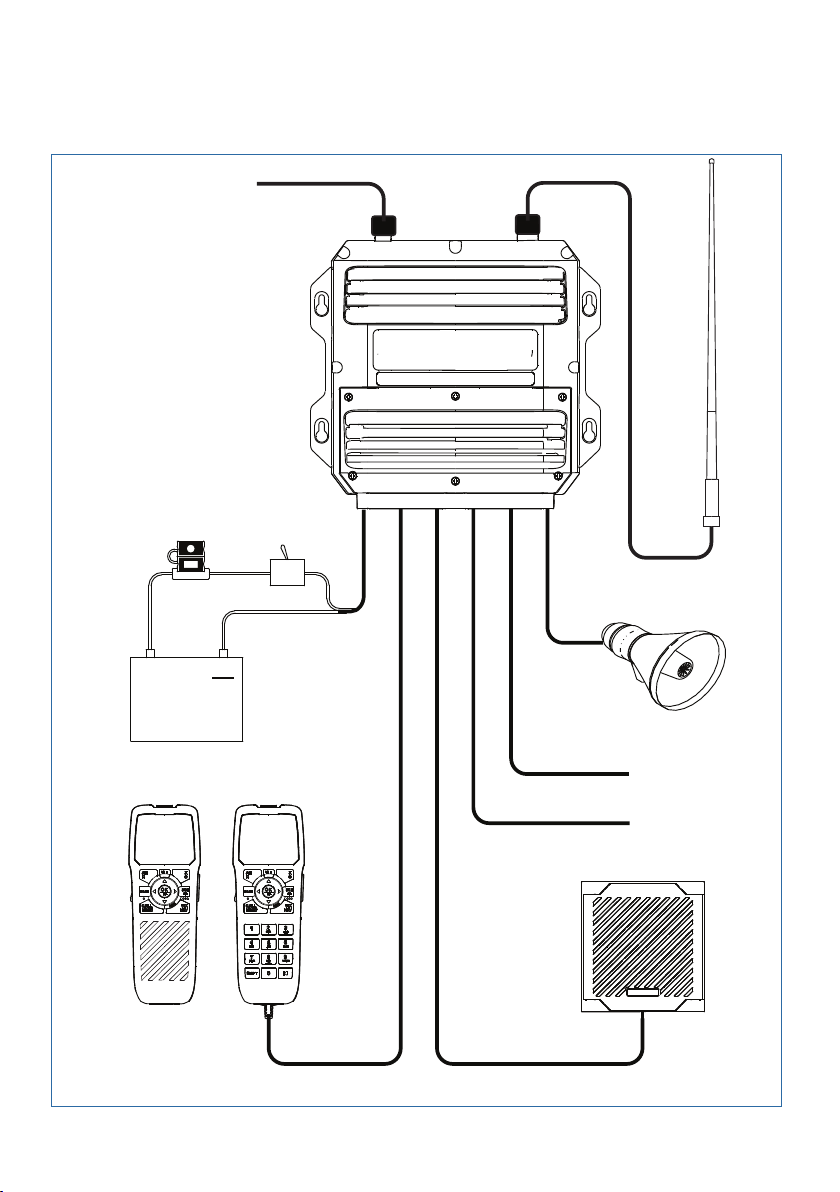
System overview diagram
+
12 VDC
10
9
1
2
8
14 |
7
6
4
5
3
System overview | V90 Operating Manual
Page 15

System overview diagram - legend
1 V90 VHF radio transceiver
2 12 VDC power supply
3 Wireless handset
4 Wired handset
5 External loudspeaker
6 NMEA 0183 GPS and horn button
7 AIS data output
8 Loud hailer speaker
9 VHF antenna
10 NMEA 2000 network connection
System overview | V90 Operating Manual
| 15
Page 16

3
Getting started
Caution: Under extreme operating conditions, the
Handsets
All the operating functions of the V90 are carried out using the
handsets. Each handset contains a microphone, a small internal
loudspeaker and various buttons for controlling the radio.
Two types of handset are available:
• Up to four wired handsets can be connected. There must be at
• Up to two wireless handsets can be installed. The wireless
When there are multiple handsets, they are synchronized so that
there is no conflict of operation and they each display the same
information on their screens.
temperature of the rear heat-sink on this radio may
exceed normal surface temperatures.
Caution is advised to prevent possible skin burns.
least one wired handset connected to the station one terminal in
the installation.
handsets communicate with the transceiver by 2.4 GHz radio
communication. The wireless handsets are powered by internal
rechargeable batteries, and are charged by inductive charging
when on the cradle.
16 |
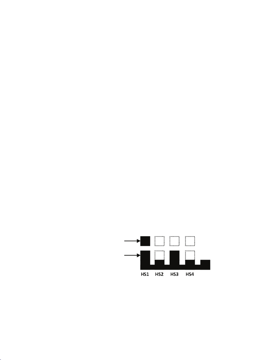
Handset naming
Handset names appear on screen at times—for example, when
another handset has control of the radio.
Wired handsets HS1, HS2, HS3, HS4
The above handsets—1 standard and 3 optional—are connected to
the transceiver. The volume controls on these handsets control the
corresponding external speakers.
Getting started | V90 Operating Manual
Page 17

Handset parts
1
3
4
2
5
6
1 Red distress cover with button beneath
2 Screen
3 PTT button
4 Volume control
5 Function keys
6 Keypad (wired handsets only).
Subscribing a wireless handset
At installation time, wireless handsets must be registered in the
transceiver. For instructions, see “Subscribing a wireless handset” on
page 74.
Getting started | V90 Operating Manual
| 17
Page 18

Charging a wireless handset
When a wireless handset is not in use, it should be placed on its
cradle for charging.
18 |
Locate the bottom of the handset onto the cradle first, and then
press the top of the handset inwards until it clicks into the top lugs.
Handset operation priority
If you want to use HS1, but it displays “HS# IN USE,” it means that
another handset is operating.
To shift control to HS1:
1. Press [X].
2. The display shows “Take Control?”
• Press [OK] to take over control.
• Or, [X] to leave the other handset in control.
Getting started | V90 Operating Manual
Page 19

Handset control buttons
10
1
2
3
4
5
9
1 Short press for AIS menu.
Long press for Hailer mode.
2
Press to select the priority channel.
3 Short press for Exit key.
Long press for power on/off.
4 Squelch keys. Also used for moving cursor left/right.
5
Three favorite channel key.
6 Short press for weather station (US models).
Long press for Navigation mode.
7
Change channel, or scroll menu options.
8 Short press for [OK] key.
Long press to toggle high/low power.
9 Short press for DSC menu.
Long press for menu.
10 Short press to start dual-watch or tri-watch mode.
Long press to start scanning channels.
8
7
6
For more information on keys, see “Appendix 2 - Keys reference” on
page 100.
Getting started | V90 Operating Manual
| 19
Page 20

Keys
16
Some keys on the handsets have more than one function,
depending on what mode the radio is in. For example, [OK] for
accepting input and [H/L] for selecting high or low transmission
power are activated using the same key. To activate the lower
function on the key label, press and hold the key until the radio
responds.
A complete reference to keys is given in “Appendix 2 - Keys
reference” on page 100.
Softkeys
A softkey is a name that appears at the bottom of the screen, and
that can be selected using the [SCAN] and/or [OK] and/or [3CH]
keys during DSC operations.
Dot symbols on the handset keys and just under the display screen
indicate which keys correspond to the softkeys as follows:
• • • • • •
[SCAN] key [OK] key [3CH] key
20 |
Hi
DSC
C
ROUTINE FROM
SUNBIRD
NO AUTO S W
CH09 REQUEST
NEW-CH ABLE
CIS
01:15
PRI
ASU
In the illustration above, you would press [SCAN] for NEW-CH
(request new channel), or [OK] for ABLE (accept proposed channel).
The use of these keys is further explained in the DSC section of this
manual.
Getting started | V90 Operating Manual
Page 21

Switching on and o
Switching on the system
The VHF radio is switched on from a wired handset.
To switch on the radio:
1. Press and hold [X] on a wired handset until the startup screen
showing version numbers appears.
2. When prompted, press [X] to exit the startup screen and display the
main operating screen.
This switches on the transceiver and the wired handset.
¼ Note: A wireless handset can only switch itself on and off. See
“Switching on a wireless handset” on page 22.
Switching o the system
The system is switched off by holding down the [X] key on a wired
handset until the display shows “Release the key to power off.”
Just one handset
1. In standby mode, press [X] on the wired handset until the display
shows “Release key to power off.”
2. Release the [X] key.
More than one wired handset
HS1 (handset 1) has a power-off menu. All the other handsets
simply power themselves off.
Handset 1 power-off menu:
• SYSTEM
Turns off all handsets and the transceiver.
• HS1
Turns off the handset itself.
Displays “SYSTEM IS WORKING” with no backlight.
¼ Note: You can ignore the power-off menu and keep holding down
[X] until the display shows “Release the key to power off.”
Getting started | V90 Operating Manual
| 21
Page 22
Switching on a wireless handset
• Press and hold [X] until the display illuminates.
The display shows “Searching,” then “Connecting,” and then the
current operating screen.
¼ Notes:
• This only switches on the individual wireless handset, not the
transceiver.
• If the transceiver is off, the wireless handset continues to display
“Searching.”
• At install time, wireless handsets must be subscribed. See
“Subscribing a wireless handset” on page 74.
Switching o a wireless handset
¼ Note: This procedure only switches off the wireless handset. It does
not switch off any other handsets or the transceiver.
1. Press and hold [X] until the following message appears:
“Release key to power off.”
2. Release the [X] key.
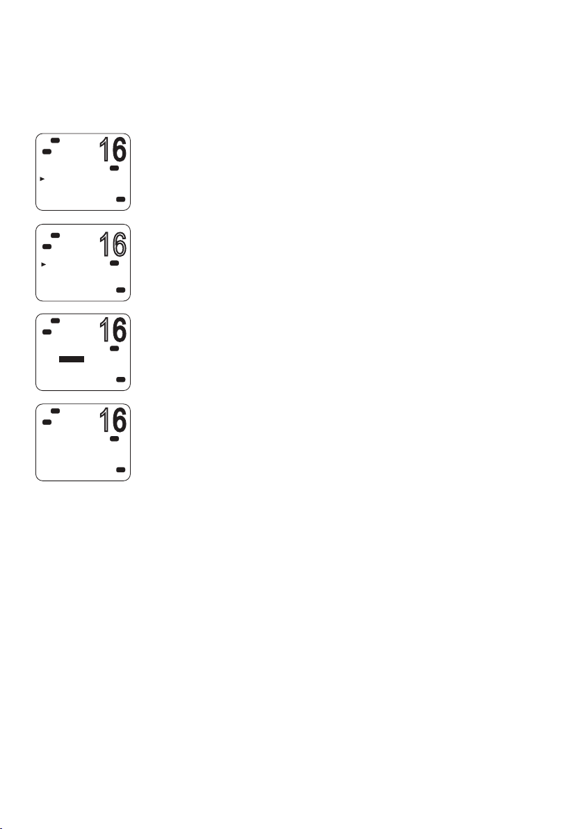
Handset status display
22 |
A small icon located on the lower right of the screen shows the
status of all connected handsets.
This handset is
Handset online
Wireless
The above example shows that handset 1 and handset 3 are online
and this handset is handset 1.
Getting started | V90 Operating Manual
Page 23

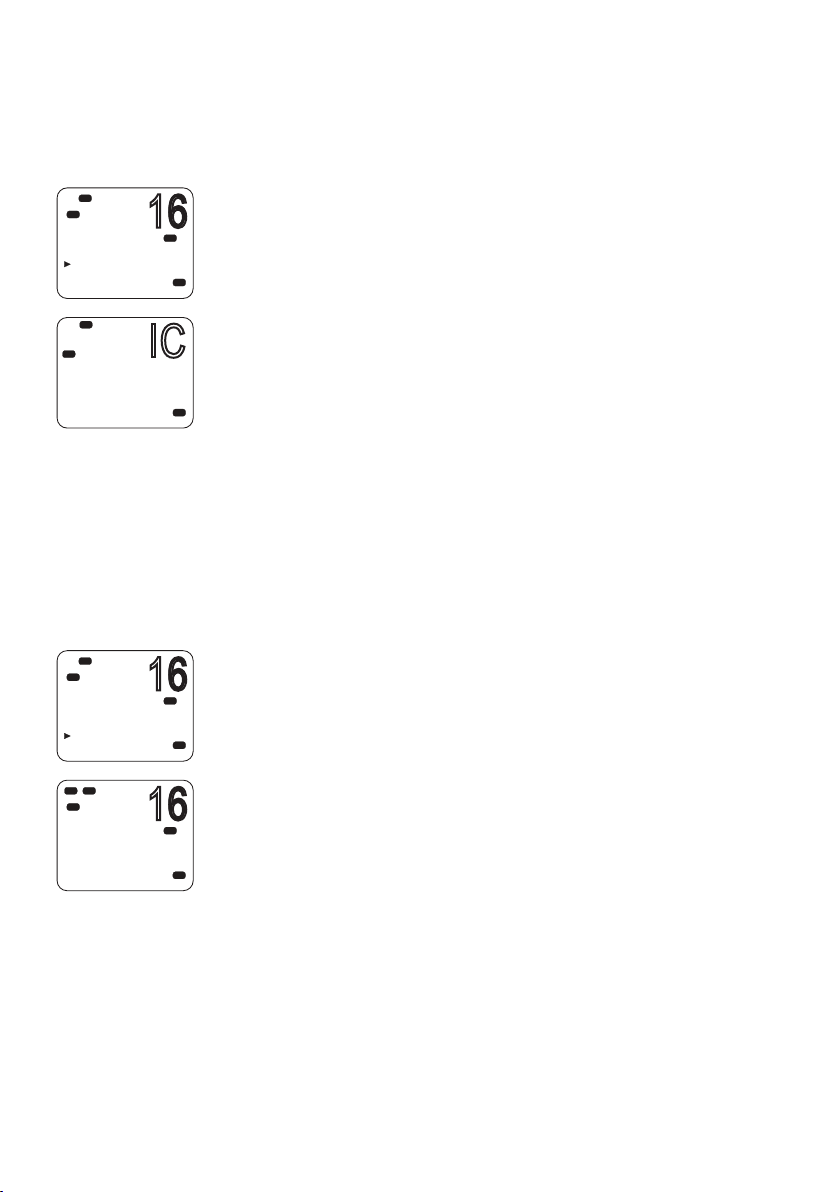
The standby screen
16
The following illustration shows a typical operating screen in
standby mode. The radio is in standby mode when it is waiting to
send or receive calls.
DSC
Hi
DISTRESS
14:43
128
012
HARBR
The above screen shows:
• The radio is tuned to channel 16, which has been designated as
• In this unit, Channel 16 has been named “DISTRESS.”
• Transmitting power is set to high (Hi).
• DSC is enabled.
• The time is 14:43 UTC.
• The current course is 128° true and speed over ground is 5.0
• The current latitude is 55°33.122’N and longitude 012°42.408’E.
• The channel bank selected is International (INT).
• The name of the destination waypoint is HARBR. It is 8 nautical
UTC
5
Kt
t
8.00
N
E
n
m
0.00
33.122
55
42.408
t
275
the priority channel (PRI).
knots.
miles away at a bearing of 275° true.
PRI
INT
Modes
The V90 has several different modes of operation. The main mode
is standby mode, during which the radio is ready to send or receive
VHF calls. Generally, pressing the [X] key will exit any special mode
and return to standby mode.
Getting started | V90 Operating Manual
| 23
Page 24

Scanning mode
In scanning mode, the radio scans selected channels for radio
activity.
Navigation mode
Navigation mode displays distance and bearing to a selected
waypoint.
Hailer mode
Hailer mode allows you to use the radio to hail other vessels or deck
crew through a connected loud-hailer speaker.
Fog horn mode
Fog horn mode allows you to use the radio to sound a fog horn
tone through a connected loud-hailer speaker.
Intercom mode
Intercom mode allows you to use the handsets to communicate
from one handset to the others in your vessel.
Standby Mode
In standby mode, the V90 displays the main operating screen on
the handset(s) and is ready to send or receive calls on the selected
channel.
24 |
Changing channel
Different jurisdictions in the world have allocated different sets
of VHF radio channels for different purposes. These sets are
known as channel banks. The available channel banks and their
corresponding channels are given in “Appendix 11 - US and ROW
VHF marine channel charts” on page 114.
Normally the radio should be left tuned to the priority channel
(CH16 or CH09) in case an emergency call is broadcast on that
channel. The V90 can also be set to monitor several channels at the
same time. In this case, the radio continuously scans the selected
channels and, if activity is heard on a channel, it will switch to that
channel while the activity continues. Then it will revert to scanning.
See “Scanning channels” on page 34.
Getting started | V90 Operating Manual
Page 25

You can use one of the following methods to change channel:
• Press [16/9] to switch immediately to the priority channel (see
“Priority channels” below).
• Press ▲ or ▼ until you reach the required channel number.
• Press and hold ▲ or ▼ to rapidly scroll through the channel
numbers. When the number you require is displayed, release the key.
• Input the number on the keypad (wired handset only), and when
the required channel number is flashing on screen, press [OK], or
wait for 2 seconds for the number to be accepted automatically.
When entering a single-digit channel number, prefix the channel
number with 0.
• Repeat press [3CH] to scroll through your three favorite channels.
See “Three favorite channels 3CH” on page 34.
• Press [WX] and then ▲ or ▼ to tune to a weather station (US model
only). See “Receiving weather alerts (US model only)” on page 32.
• Press [WX] to go directly to a set favorite channel (EU models only).
Priority channels
Channel 16 is the international emergency priority channel.
On Channel 16, operators must give priority to any emergency
calls occurring on that frequency. In the US, Channel 9 is also an
emergency priority channel.
To switch directly to Channel 16 (or Channel 9 if congured):
• Press the 16/9 button.
16 / 9
¼ Note: The default emergency channel is CH16. On US models of
the radio, you can change the default emergency channel to CH9
by holding down 16/9 until the unit beeps and displays 09. Repeat
the procedure to change back to CH16 as the default emergency
channel.
Getting started | V90 Operating Manual
| 25
Page 26

Special channel A/B
Certain USA channels have ‘A’ or ‘B’ suffixes.
“A” indicates simplex use of the ship station transmit side of an
international duplex channel, and that operations are different than
international operations on that channel. “A” channels are generally
only used in the United States, and use is normally not recognized
or allowed outside the U.S. “B” indicates simplex use of the coast
station transmit side of an international duplex channel. The U.S.
does not currently use “B” channels for simplex communications in
this band.
Adjusting the volume
The volume control on the right hand side of the handset provides
up and down control of the handset speaker volume and the
external speaker volume.
Adjusting squelch
The squelch adjustment allows you to adjust the sensitivity of
the radio so that background noise is minimized. In areas of high
static noise, such as close to large cities, you can improve quality of
reception by adjusting the squelch.
• Use the ◄ and ►keys to adjust the level up or down respectively.
• Adjust the level until the background noise just disappears.
26 |
¼ Notes:
• You can also adjust the sensitivity of the VHF receiver using the
Local/Distance setting. See “Radio sensitivity” on page 97.
• The ◄ and ►keys are also used for moving the cursor when
entering data on a wired handset.
Getting started | V90 Operating Manual
Page 27

Setting transmission power
The V90 has two transmission power settings:
High 25 W
Low 1 W
To change the power setting:
Press and hold [H/L] until the Hi or Lo icon on the display changes.
¼ Notes:
• Channel 16 always remains in high transmission power.
• Some channels allow only low-power transmissions. If you try to
change to high power, the V90 will sound an error beep.
• Some channels allow only low power transmissions initially, but can
be forced to high power by holding down [H/L] and PTT at the same
time.
• See “Appendix 11 - US and ROW VHF marine channel charts” on
page 114 for a list of channel data.
PTT key
The Push to Talk (PTT) key activates the microphone and transmits
your voice over the selected channel.
¼ Notes:
• Pressing PTT while a menu is displayed will exit the menu without
making any selection.
• DSC transmission has higher priority than PTT voice transmission.
• During PTT transmission, the radio cannot receive a DSC call.
• If PTT gets stuck or accidentally held in the talk position, a built-in
timer sounds an error beep and shuts down the transmission after 5
minutes.
Getting started | V90 Operating Manual
| 27
Page 28

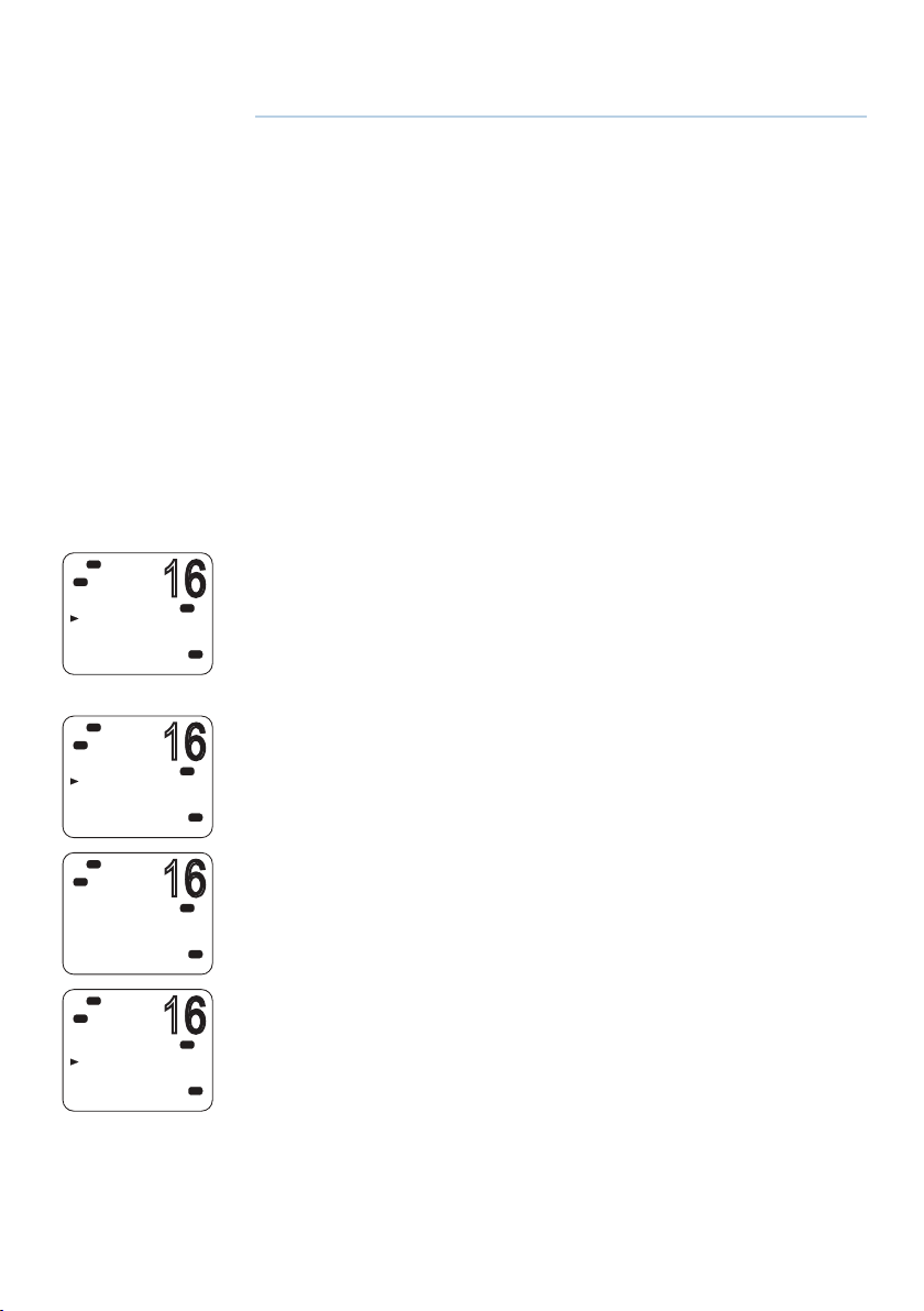
Using the menus
16
16
Hi
DSC
C
DSC SETUP
USER MMSI
GROUP SETUP
INDIV REPLY
DSC FUNC
Hi
DSC
C
MENU SELECT
WAYPOINT
N2K D ATA
VOICE REC
BACKLIGHT
The [CALL/MENU] button provides access to two different menus as
PRI
follows:
• Short press to access the DSC menu.
USA
• Long press (press and hold) to access the main menu.
To use the menus:
PRI
USA
• Use ▼ or ▲ to scroll to the option you want.
• Press [OK] to select a menu option, or
• Press [X] to go back without selecting an option.
¼ Note: If the radio is left in menu mode, after a default time of
10 minutes, it beeps a warning and then automatically returns to
standby mode.
Shortcut keys
The V90 wired handset keypad includes a SHIFT key that modifies
the function of some keys.
• Press [SHIFT] to display the shift icon (S), and then press the number
key to access the required function.
Some menu items can be accessed via shortcut keys.
For a list of shortcut keys, see “Appendix 3 - Shift keys” on page 103.
28 |
Getting started | V90 Operating Manual
Page 29

Entering data
Entering data with a wired handset
Enter data using the keypad. The first press of a key inputs the
number corresponding to the key; subsequent presses input letters
of the alphabet as indicated on the key. For example, 2, A, B, and C
are typed using the same key.
After a short pause, the cursor automatically jumps to the
next space; or, you can press [OK] to move to the next space
immediately.
¼ Note: Characters can only be entered in upper case.
To replace a character:
• Use the ◄ and ►keys to move the cursor to the character. You can
then type over the character.
To nish entering data:
Press [OK] repeatedly to reach the end of the line. The cursor will
then move to the next input required, or a save/cancel option will
be displayed for you to select as required.
¼ Note: You can press [X] at any time to go back one step.
Entering data with a wireless handset
Use the ▲and ▼keys to scroll through the available characters, and
then press [OK] to select the required character.
Warning messages
See “Appendix 6 - Warning messages” on page 105.
Alert tones
See “Appendix 5 - Beep tones and call alerts” on page 105.
Getting started | V90 Operating Manual
| 29
Page 30

4
Operating procedures
Making a routine radio call
Making a routine ship to ship or ship to shore call.
1. Select a calling channel.
See “Changing channel” on page 24.
2. Listen to make sure that there is no traffic on the channel.
3. Hold down [PTT] and announce the station you want to contact
and your own vessel’s details. When you have finished speaking, say
“Over” and then release [PTT].
4. When you receive a reply on the calling channel, agree a working
channel.
5. Change to the working channel.
6. Continue the conversation:
• Hold down [PTT] while you are speaking.
• Release [PTT] while you are listening.
7. When finished, press [16/9] to return to the radio watch channel.
¼ Note: When you call a coast station, the coast station operator
normally states a suitable working channel.
30 |
Calling a buddy
You can call a buddy using their MMSI on the DSC system. For
further information, see “Introduction to DSC” on page 45.
Operating procedures | V90 Operating Manual
Page 31

Making a channel 16/9 distress call
1. If not already on the priority channel, press the [16/9] key.
16 / 9
2. Listen to make sure there is no traffic on the channel.
3. Hold down [PTT] and announce your distress call.
4. Say your call sign, details of your vessel, its position and the nature of
the distress.
5. Say “over” and then release [PTT] when you have finished speaking.
6. Allow a short time for a reply.
7. If you don’t hear a reply, repeat the distress call (steps 3 to 6 as
above).
8. When you receive a reply, continue the conversation:
• Hold down [PTT] while you are speaking.
• Release [PTT] while you are listening.
You may be asked to change to a working channel.
¼ Notes
• In the USA, you can toggle between Channel 16 and Channel 9 as
the priority channel. Hold down [16/9] until a beep sounds and the
required priority channel is displayed.
• This feature needs to be setup in the radio settings (“Setting the
priority channel” on page 79).
Making a DSC distress call
Using the DSC system (where available) you can make a distress
call by pressing a single Distress button. For further information, see
“Introduction to DSC” on page 45.
Operating procedures | V90 Operating Manual
| 31
Page 32

Receiving weather alerts (US model only)
The National Oceanic and Atmospheric Administration (NOAA)
provides several weather forecast channels on USA and Canadian
channel banks. If severe weather is forecast, the NOAA broadcasts a
weather alert on 1050 Hz.
To access weather alerts:
1. Short press [WX] to enter WX mode.
2. Press ▲ or ▼ to change WX channel.
3. If WX TONE ALERT setting is ON (see “Setting up weather tone alert”
on page 80), the radio will monitor the WX channel you select.
If an alert tone is broadcast from the NOAA weather station, the
weather alert is picked up automatically and the V90 alarm sounds.
Press any key to cancel the alarm and to hear the weather alert
message.
4. When finished, press [WX] again or [X] to exit WX mode.
¼ Note: In WX mode, the Wx icon appears on screen.
Receiving SAME alerts (US model only)
The NOAA All Hazards Weather Radio Service (NWR) works in
conjunction with the Emergency Alert System (EAS) to issue
weather alerts for specific geographic areas or weather warnings.
It uses a digital encoding system known as Specific Area Message
Encoding (SAME) to broadcast these alerts.
32 |
Each transmitter in the NWR network is identified with a unique
6-digit SAME code.
If SAME is enabled and the 6-digit country IDs you want to monitor
have been entered, the radio will sound the weather alarm when it
detects a weather alert on the selected weather channel.
For SAME alert setup, see “Setting up SAME alert” on page 81.
Operating procedures | V90 Operating Manual
Page 33

Receiving a SAME ALERT
If SAME ALERT is ON and an NWR or EAS alert for your geographic
area is broadcast, the V90 detects the alert signal and sounds the
alarm.
Press any key to cancel the alarm.
• If the alert is being sent by NOAA NWR, the radio automatically
tunes to the designated frequency so that you can listen to the
alert.
• If the alert is being sent by the EAS, the nature of the alert is shown
on screen as WARNING, WATCH, ADVISORY, or TEST.
Press any key to show the nature of the alert.
¼ Note: The list of alerts is shown in “Appendix 5 - Beep tones and
call alerts” on page 105.
Receiving SAME TEST messages
In addition to the WARNING, WATCH and ADVISORY alerts, the
EAS also send out TEST messages so that you can check that your
WX ALERT setup is working correctly. The TEST message is usually
transmitted between 1000 and 1200 (10.00AM and noon) every
Wednesday.
If your WX ALERT setup is working correctly, the alert sounds and
TEST is displayed on screen, followed by a broadcast message
from the National Weather Service.
¼ Note: If there is a threat of severe weather, the test will be
postponed until the next fine weather day.
Favorite channel (non-US models)
In standby mode, press [WX] to access your favorite channel, press
again or [X] to go back to the last working channel.
¼ Notes:
• To set up the favorite channel, see “Setting up a favorite channel”
on page 80.
• You can store just one channel as the favorite channel. It can, for
example, be a weather reporting station.
Operating procedures | V90 Operating Manual
| 33
Page 34

Lo
03
16
DSC
OVER WRITE
CH3?
YES
NO
Hi
DSC
3CH MODE
DELETE CH1?
YES
NO
Three favorite channels 3CH
• Once set up, you can use the three favorite channels in two ways:
• Repeat press [3CH] to toggle between your three favorite
channels, or
• Scan the three channels and the priority channel.
To add a favorite channel:
• To add a favorite channel for the first time, select that channel then
hold 3CH to store it in the CH1 location.
• You can repeat the procedure to store two more favorite channels in
A
USA
D
CH1
USA
the CH2 and CH3 locations respectively.
• Once the three locations are full, if you try to add another favorite
channel, the radio will overwrite the CH3 location after prompting
you to confirm.
To delete a favorite channel:
• Select that channel and then hold down [3CH]. The radio will
remove that favorite channel after prompting you to confirm.
To toggle between your three favorite channels:
• Press [3CH] to enter 3CH mode.
• The radio displays “3CH MODE” and CH1, CH2, or CH3 to show which
of your favorite channels is currently selected.
• Repeat press [3CH] to switch between the three channels.
34 |
To exit 3CH mode:
• Press [X].
Scanning channels
The V90 can automatically monitor more than one channel at the
same time. It scans a selected range of channels, and when a valid
signal is received, the radio stops scanning and remains on that
channel so that you can hear the communication. However, if the
signal from the channel ceases for more than 5 seconds, the scan
automatically restarts.
Four scan modes are provided:
• All scan
Scans all available channels in sequence, but also checks the priority
channel every 2 seconds.
Operating procedures | V90 Operating Manual
Page 35

• Dual watch scan
Scans the selected channel and channel 16.
• 3CH scan
Scans your three favorite channels and the priority channel.
• Tri watch scan (US models only)
Scans the current channel, channel 16 and channel 9.
ALL SCAN mode
Hold down [SCAN] for about 3 seconds to start ALL SCAN mode.
The radio displays the SCAN icon and “ALL SCAN.” You will see the
channel numbers changing.
• If you hear a communication of interest, press [SCAN] or [PTT] to
stop at the currently scanned channel.
• Press [X] to quit scan mode and return to the previously selected
channel.
¼ Notes:
• Scan is not allowed in some EU countries.
• If TONE ALERT or SAME is enabled (US models only), the weather
channel is also scanned.
Skipping busy channels
If one channel is always busy with traffic, you can set the radio to
skip that channel during scanning.
To skip a channel:
• While the channel is displayed during scan, press [OK] to skip over it.
To resume scanning a skipped channel:
• With scanning OFF, as you scroll up and down through channels, the
SKIP icon will be displayed when you are on a skipped channel. With
the SKIP channel selected, press [OK] to cancel the SKIP function.
¼ Notes:
• You cannot skip the priority channel.
• The SKIP icon will disappear when the radio is powered OFF/ON.
Operating procedures | V90 Operating Manual
| 35
Page 36

3CH scan mode
• With any of your favorite channels selected (by pressing the 3CH
key), hold down [SCAN] to start scanning your favorite channels and
the priority channel.
• Press [SCAN] again to stop at the broadcast channel.
• During scanning, press [X] to cancel 3CH scanning and return to the
previously selected channel.
• Press SCAN or PTT to stop at the currently scanned channel.
• To scan only one of your favorite channels, press 3CH then
immediately press and release SCAN.
For further information on 3CH, see “Making a routine radio call” on
page 30.
¼ Note: 3CH scan functionality is limited in some European countries
and, if ATIS is enabled, the 3CH scan mode will be disabled.
Dual watch scan
Dual watch scan monitors the current working channel and the
priority channel.
To enter dual watch scan:
• Short press [SCAN].
The DW icon will be displayed on screen.
36 |
To exit dual watch scan:
• Press [SCAN] or [X].
¼ Notes:
• For US models, you can select Channel 9 as the priority channel
(see “Priority channels” on page 25 ).
• To scan both channel 16 and channel 9, see “Tri watch scan”
below.
Operating procedures | V90 Operating Manual
Page 37

16
Hi
16
16
DSC
C
HAILER
HAILER
FOG HORN
INTERCOM
ANNOUNCE
Hi
DSC
HAILER
OUTPU T
VOL
LO HI
Tri watch scan
(US models only)
Tri watch monitors the current working channel, Channel 16 and
Channel 9.
For tri watch, you need to enable both channel 16 and channel 9 as
priority channels. See “Setting the priority channel” on page 79.
To enter tri watch scan:
• Short press [SCAN].
The TRI icon will be displayed on screen.
To exit tri watch scan:
• Press [SCAN] or [X].
Using the hailer
If the V90 is connected to a suitable public address (PA) speaker, you
PRI
USA
PRI
USA
can use the Hailer function to hail other vessels or deck crew. The
Hailer function also features a listen-back mode, which uses the PA
speaker as a microphone to listen for a response.
1. Press and hold [AIS/IC] until the HAILER menu appears.
2. Select HAILER.
3. Press [PTT] to talk.
4. Release [PTT] to listen for a response.
Hi
DSC
DSC
HAILER
LISTEN
5. When finished, press [X] to exit Hailer mode.
PRI
¼ Note: While pressing [PTT], you can change the volume of the PA
speaker using the volume control on the side of the handset.
USA
Operating procedures | V90 Operating Manual
| 37
Page 38
16
Hi
16
16
16
DSC
C
HAILER
HAILER
FOG HORN
INTERCOM
ANNOUNCE
Lo
Hi
DSC
FOG HORN
HORN
UNDERWAY
STOP
SAIL
Hi
DSC
DSC
HORN
OUTPU T
VOL
LO HI
Hi
DSC
HORN
LISTEN
Using the fog horn
If the V90 is connected to a suitable public address (PA) speaker,
you can use the Fog Horn function to sound certain international
standard fog horn tones through the PA speaker.
1. Press and hold [AIS/IC] until the HAILER menu appears.
PRI
2. Select FOG HORN.
USA
PRI
USA
PRI
USA
PRI
USA
There are 8 internationally recognized fog horn signals available:
HORN Manual operation
UNDERWAY One long tone
STOP Two long tone
SAIL One long, two short
ANCHOR One long warble
TOW One long, three short
AGROUND Warble sequence
SIREN Manual operation
3. Select the required signal, then press [OK] to start.
• Press [OK] to sound the HORN or SIREN.
• The other signals will sound automatically approximately every
two minutes until you press [X] to cancel.
4. When finished, press [X] to exit horn mode.
¼ Notes:
38 |
• When the fog horn is not sounding, it is in Listen mode.
• While pressing [PTT], you can change the volume of the PA
system using the volume control on the side of the handset.
• In Horn mode, you can press [PTT] to talk through the PA
speaker.
• If a horn button has been installed, you can press the button for
a momentary sounding of the horn.
Operating procedures | V90 Operating Manual
Page 39
Using the intercom
16
IC
16
16
When two or more handsets (wired or wireless) are installed, you
can use the radio to communicate between handsets.
Lo
Hi
DSC
HAILER
HAILER
FOG HORN
INTERCOM
ANNOUNCE
Lo
DSC
INTERCOM
PUSH TO TALK
Hi
DSC
HAILER
HAILER
FOG HORN
INTERCOM
ANNOUNCE
Lo
Hi
TX
DSC
MAN
ANNOUNCING
1. Press and hold [AIS/IC].
2. Select INTERCOM from the menu.
PRI
3. Press [PTT] to talk.
USA
4. When finished, press [X] to quit Intercom mode.
¼ Notes:
• Intercom mode only works when one or two wireless handsets are
installed. While the intercom is being used, the VHF radio is disabled,
USA
except for incoming DSC calls.
• The intercom system is half duplex; you cannot receive and transmit
at the same time; you must release the [PTT] key to listen.
• The receiving handset(s) can adjust their volume controls.
Using the announce function
You can use the handset to make announcements to the other
handsets and any external speakers that are connected.
1. Press and hold [AIS/IC] until the HAILER menu appears.
2. Select ANNOUNCE.
PRI
3. Press [PTT] to talk.
USA
4. When finished, press [X] to exit Announce mode.
¼ Notes:
• The Announce function does not listen for a response.
PRI
• During Announce mode, if a voice signal is received on a VHF
USA
channel, an Rx icon appears on screen.
• If an alert such as ATIS, AIS, DSC or WX is received, or the [DISTRESS]
key is pressed or a DSC call received, the radio will exit Announce
mode and handle the alert or DSC call.
Operating procedures | V90 Operating Manual
| 39
Page 40

Using the voice recorder
When activated, the voice recorder function records all received and
transmitted voice communications.
If memory is full, it will overwrite previous recordings.
Recording
Long press the voice recorder key to access the recording menu.
Select RECORDER and then ON’ to enable the recording function.
¼ Note: Voice recording is ON by default.
Playback
Press the voice recorder key to play the recording. A playback icon
will be displayed on lower right of the screen. During playback,
select ‘FWD 5S’ from the menu to fast forward 5 seconds.
When finished playing back, the radio will return to standby mode.
Sharing NMEA 2000 data
NMEA 2000 (N2K) is a communications network standard used for
connecting marine electronic devices. It is the successor to NMEA
0183.
40 |
¼ Note: The V90 also supports NMEA 0183.
Various devices can be connected via a network cable and can share
data on the network. This allows the devices to work together and,
for example, one display unit can show information from different
sources.
The V90 uses N2K to share the following data:
• Waypoint data to a chartplotter. See “Sending waypoint data to a
chartplotter” on page 44.
• AIS
• Display navigation data received from other devices: Depth, speed,
course, heading and wind data.
Operating procedures | V90 Operating Manual
Page 41
5
16
16
16
16
Waypoint procedures
A waypoint refers to the latitude, longitude and name of a place that
you have entered into the radio. A waypoint can be a destination, a
point along a planned course, or any location useful for navigation,
such as a fishing spot.
You can use waypoints as follows:
• Display the coordinates, bearing and distance to a waypoint on
the standby screen. See “Navigating to a waypoint” on page
43.
• Output a waypoint’s coordinates and other details via NMEA
2000 for display on a chartplotter or other compatible device.
See “Sending waypoint data to a chartplotter” on page 44.
¼ Note: The V90 can store up to 200 waypoints.
Hi
DSC
C
MENU SELECT
WAYPOINT
N2K D ATA
VOICE REC
BACKLIGHT
Hi
DSC
C
WAYPOINT
WP LIST
NEAREST WP
Hi
DSC
C
WP LIST
NEW W P
Lo
Hi
DSC
C
SAV E
YES
NO
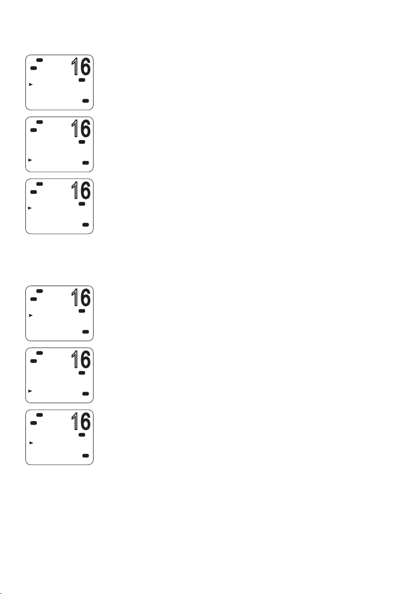
Adding a new waypoint
1. Select MENU → WAYPO IN T → W P LIS T.
PRI
Your waypoint list will be displayed.
USA
2. Press [OK].
NEW WP starts to flash.
3. Press [OK] again to add a new waypoint.
PRI
4. Enter a waypoint name (maximum 6 characters).
USA
5. Enter the latitude. Use ▲ or ▼ key to select N or S as required, and
then press [OK] to move to the longitude setting.
6. Enter the longitude. Press [OK] once you have selected E or W.
PRI
7. When prompted, select YES or NO to save the new waypoint.
USA
¼ Note: When the waypoint list is full, you must delete an entry before
you can create a new entry.
PRI
USA
Waypoint procedures | V90 Operating Manual
| 41
Page 42
Editing a waypoint
16
16
16
16
16
16
Hi
DSC
C
WAYPOINT
WP LIST
NEAREST WP
Hi
DSC
C
WP LIST
NEW W P
HARBR
FISH1
FISH2
Hi
DSC
C
HARBR
WP EDIT
DELETE
GO
TX WPT D ATA
Hi
DSC
C
WAYPOINT
WP LIST
NEAREST WP
Hi
DSC
C
WP LIST
NEW W P
HARBR
FISH1
FISH2
1. Select MENU → WAYPO IN T → W P LIS T.
PRI
USA
The display shows your list of waypoints.
2. Press [OK].
NEW WP starts to flash.
3. Scroll down to the entry you want to edit.
PRI
4. While the required waypoint is flashing, press [OK].
USA
5. To edit the waypoint, select WP EDIT.
6. Edit the waypoint name, latitude or longitude. You can press [OK]
PRI
repeatedly until the cursor moves to the required place.
7. When finished, press [OK] repeatedly if necessary to reach the SAVE
USA
prompt.
8. Select YES or NO to save the data as required.
Deleting a waypoint
1. Select MENU → WAYPO IN T → W P LIS T.
PRI
USA
PRI
USA
The display shows your list of waypoints.
2. Press [OK].
NEW WP starts to flash.
3. Scroll down to the entry you want to delete.
4. While the required waypoint is flashing, press [OK].
5. Select DELETE.
42 |
Hi
DSC
FISH2
WP EDIT
DELETE
GO
TX WPT D ATA
6. If you select YES at the prompt, the waypoint will be deleted
immediately.
PRI
USA
Waypoint procedures | V90 Operating Manual
Page 43
16
Hi
16
16
16
16
DSC
C
WAYPOINT
WP LIST
NEAREST WP
Hi
DSC
C
WP LIST
NEW W P
HARBR
FISH1
FISH2
Hi
DSC
C
FISH2
WP EDIT
DELETE
GO
TX WPT D ATA
Navigating to a waypoint
Navigating to a waypoint requires two steps:
• Selecting which waypoint you want to navigate to.
PRI
USA
PRI
USA
PRI
USA
• Pressing [NAV] to go to Navigation mode.
These steps are explained below.
Selecting a waypoint from your list
1. Select MENU → WAYPO IN T → W P LIS T.
2. Press [OK] and then scroll to the required waypoint and press [OK]
again.
3. Select GO.
4. When prompted, select YES.
When in Navigation mode (see below), the distance and bearing
from your current position to the selected waypoint will be
displayed on the bottom line of the standby screen.
Selecting the nearest waypoint
Hi
DSC
C
WAYPOINT
WP LIST
NEAREST W P
Hi
DSC
C
NEAREST W P
243
FISH1
075
FISH2
¼ Note: This option is only available when a valid signal from a GPS
device is present.
PRI
1. Select MENU → WAYPO IN T → N EA RE ST W P.
USA
The display shows your list of waypoints with the nearest at the top.
2. Scroll to the required waypoint and press [OK].
PRI
t
n
m
2
t
n
m
8
USA
When in Navigation mode, the distance and bearing to it from your
current position will be shown on the bottom line of the standby
screen.
Waypoint procedures | V90 Operating Manual
| 43
Page 44

16
Hi
16
DSC
C
FISH2
WP STOP
TX WPT D ATA
Entering navigation mode
• Long press [NAV] to enter navigation mode.
In navigation mode, the following details about the destination
waypoint will be displayed on the standby screen:
Name of waypoint
B: Bearing in degrees; ‘t’ for true
D: Distance
X: Cross track error
Cross track error is the distance the vessel is to one side of the
straight line between two waypoints.
Exiting navigation mode
• Long press [NAV] or press [X].
Stop navigating to a waypoint
1. Select MENU → WAYPO IN T → W P LIS T.
2. Press [OK] then scroll to the required waypoint and press [OK] again.
PRI
3. Select WP STOP.
USA
4. When prompted, select YES.
Sending waypoint data to a chartplotter
44 |
Hi
DSC
C
FISH2
WP EDIT
DELETE
GO
TX WPT D ATA
You can send waypoint data via NMEA 2000 to a compatible
chartplotter.
1. Select MENU → WAYPO IN T → WP LIST.
PRI
The display shows your list of waypoints.
2. Press [OK].
USA
3. Scroll to the required waypoint, and then press [OK].
4. Select TX WPT DATA to send the data to the chartplotter.
Waypoint procedures | V90 Operating Manual
Page 45

6
DSC procedures
Introduction to DSC
DSC (Digital Selective Calling) is part of the Global Maritime Distress
and Safety System. It allows radio stations to contact each other on
a dedicated digital channel (channel 70). The radios automatically
exchange the digital contact and acknowledgement messages
on channel 70, freeing up the other VHF channels for voice
communications.
Once they have established contact, both radios automatically
switch to a VHF working channel for the operators to carry out
normal voice communication.
Each DSC radio has a unique 9-digit number, known as a Maritime
Mobile Service Identity (MMSI), which is used to contact that
individual radio.
DSC radios continuously monitor channel 70 irrespective of what
other channels they are working on. If someone calls your vessel via
DSC, your radio will sound an alert tone for you to respond to the
call.
If the V90 radio is connected to a GPS system, it will automatically
send your location when calling other stations. This is especially
useful for distress calls.
DSC process
The calling and acknowledging process on channel 70 operates as
follows:
1. The calling radio transmits a DSC signal on channel 70.
2. Receiving radio(s) sound alert tones for their operators.
3. For individual, LL request and DSC test calls, the receiving radio
sends a DSC acknowledge signal on channel 70.
4. Both the calling and receiving radios switch to a working VHF
channel (except for LL request and DSC test calls).
5. Calling and receiving operators commence normal VHF voice
communications on the working channel.
6. Press [X] to return to standby mode.
DSC procedures | V90 Operating Manual
| 45
Page 46

Distress calls
DSC is particularly useful for sending distress signals to all stations.
The process is automated to the extent that if you are under stress,
you can simply press a single, dedicated distress button—the red
button beneath the red cover on top of the V90 handset.
When sending a distress call, the DSC radio automatically transmits
as much information as is available, including:
• The MMSI of the ship in distress;
• The position of the ship in distress; (If the radio is connected to a
GPS);
• The nature of the distress.
¼ Notes:
• Before the DSC functions can be used, you must enter a valid MMSI
into the V90 radio. See “Entering or viewing your individual MMSI”
on page 84.
• If the small DSC icon is not displayed on the standby screen,
DSC may have been turned off in settings. See “Enabling DSC
functionality” on page 87.
Softkeys
A softkey is a name that appears at the bottom of the screen and
provides additional functionality to the [SCAN] and/or [OK] and/or
[3CH] buttons during DSC operations.
46 |
Dot symbols on the handset keys and just under the display screen
indicate which keys correspond to the softkeys as follows:
• • • • • •
[SCAN] key [OK] key [3CH] key
The following table shows the softkeys that occur in DSC mode.
Key Label Function
ACK Acknowledge a call
ACCEPT Accept a channel request
NEW-CH Request a new channel
PAUSE Pause a call countdown sequence
RESEND Resend the call
SILENC Silence an audible alarm
DSC procedures | V90 Operating Manual
Page 47

DSC distress calls
DISTRESS
16
DISTRESS
16
DISTRESS
16
Initiating an UNDEFINED distress call immediately
1. Flip open the red cover on top of the handset.
2. Press and hold the red [DISTRESS] key for about 3 seconds.
Hi
DSC
C
DISTRES C ALL
UNDEFINED
HOLD DISTRES
3 SECONDS. .
Hi
DSC
C
DISTRES C ALL
UNDEFINED
FIRE
FLOODING
COLLISION
Hi
DSC
C
DISTRES C ALL
FIRE
HOLD DISTRES
3 SECONDS. .
The radio counts down the 3 seconds, and then:
• Beeps loudly,
PRI
USA
• Displays “DISTRESS CALL SENDING” on screen, and
• Sends out the UNDEFINED distress call to all stations on channel
70.
3. Release the [DISTRESS] key.
4. If you have time, observe any acknowledgement of your call and
follow up by sending a MAYDAY distress call on Channel 16. See
“Continuing a distress call” on page 48.
Initiating a distress call of specic nature
1. Flip open the red cover on top of the handset.
2. Press the red [DISTRESS] key briefly.
3. The radio will display a list for you to select the nature of the distress:
UNDEFINED
FIRE
PRI
USA
PRI
USA
FLOODING
COLLISION
GROUNDING
LISTING
SINKING
ADRIFT
ABANDONING
PIRACY
OVER BOARD
4. USE the ▲ and ▼ keys to reach the required nature of distress, and
then press and hold the [DISTRESS] key for about 3 seconds.
The radio counts down the 3 seconds, and then:
• Beeps loudly,
• Displays “DISTRESS CALL SENDING” on screen, and
• Sends out the specified distress call to all stations on channel 70.
5. Release the [DISTRESS] key.
DSC procedures | V90 Operating Manual
| 47
Page 48

Continuing a distress call
1. After you have initiated a distress call as above, the radio goes
into call repeat mode—it automatically repeats the distress call
approximately every 4 minutes, until the call is acknowledged by an
official search and rescue station.
The display shows the time remaining to the next resend.
You can press ▼ or ▲ to scroll through the transmitted Distress call
information.
2. You now have the following softkey options:
• RESEND
Displays “HOLD DISTRESS 3 SECONDS TO SEND.” You can then:
• Hold down the red [DISTRESS] key for 3 seconds to resend the
call, or
• Press the [EXIT] softkey to return to waiting for an
acknowledgement.
• PAUSE
Pauses the call repeat mode. You can then:
• Press the [EXIT] softkey to resume the same call.
• CANCEL
Displays “DISTRESS CALL SEND CANCEL.” You can then:
• Press the [NO] softkey to return to waiting for an
acknowledgement.
• Press the [YES] softkey to send the DISTRESS CANCEL signal.
• Press [PTT] and report your situation using the handset.
• When finished talking, press [X] to return to standby mode.
48 |
3. After receiving an acknowledgment, press the [SILENC] softkey.
4. Press [X] to quit the current distress acknowledgment.
¼ Notes:
• Prior to receiving an acknowledgement, you cannot terminate the
distress alert call. It can only be cancelled by completing the distress
call cancel process as described above.
• Call information is stored in the Distress Call Log. See “Calling using
the distress log” on page 57.
DSC procedures | V90 Operating Manual
Page 49

Receiving a distress call
When the radio receives a DSC distress call, it:
• Sounds a two-tone alarm through the handset(s) and speaker(s),
and
• Automatically switches to channel 16 after 10 seconds if there is
no user intervention.
If the two-tone distress alarm sounds on your radio:
1. Press the [SILENC] softkey to silence the alert.
You do not need to send a DSC acknowledgement; this will be done
by an official search and rescue station.
2. Maintain a listening watch on Channel 16 for voice communications
from ship and coast stations about the distress.
3. You can then:
• Press ▼ or ▲ to scroll through details of the distress call,
• Press [PTT] to talk, or
• Press [X] to exit the DSC session.
Distress acknowledgement (DISTRESS ACK)
or distress relay all ships (DISTRESS REL)
Only official Search and Rescue stations are permitted to send these
signals.
When your radio receives a Distress Acknowledgement signal it
does the following:
• Cancels any Distress Mode transmissions,
• Sounds a two-tone alert, and
• Automatically switches to channel 16 after 10 seconds if there is
no user intervention.
1. Press the [SILENC] softkey to silence the alert.
2. Press the [ACCEPT] softkey to switch to CH16 immediately.
3. Maintain a listening watch on CH16, and standby to give assistance.
4. You can:
• Press ▼ or ▲ to scroll through details of the call,
• Press PTT to talk to the coast station or other ship, or
• Press [X] to exit the DSC session.
DSC procedures | V90 Operating Manual
| 49
Page 50

Distress relay individual (INDIV DISTR RELAY)
When the radio receives an Individual Distress Relay call, it sounds
the alert tone and displays INDIV DISTR RELAY.
1. Press the [SILENC] softkey to silence the alarm.
2. You can then:
• Press ▼ or ▲ to scroll through details of the call.
• All models
Press the [ACCEPT] softkey to immediately accept the change to
CH16.
¼ Note: The radio automatically changes to CH16 after 10 seconds.
• US models
Press [ACK] softkey to ACK the call.
• Press [X] to quit the current DSC session.
50 |
DSC procedures | V90 Operating Manual
Page 51
Lo
08
16
AIS
DSC
SUNBIRD
INDIVIDUA L
ROUTINE
WAIT..00:10
X-->EXIT
Lo
AIS
DSC
C
SUNBIRD
SEND AGAIN
YES
NO
Sending routine DSC calls
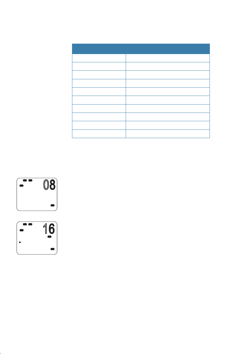
Briefly press [CALL / MENU] to access the DSC menu options:
Call type Page
INDIVIDUAL page 52
LAST CALL page 53
GROUP page 54
ALL SHIPS page 55
CALL LOG page 56
DISTR LOG page 57
SENT CALL page 58
LL REQUEST page 58
TRACK BUDDY page 59
DSC TEST page 62
The above functions are explained in the sections below.
To make a DSC Distress call, see “DSC distress calls” on page 47.
General usage
• When an alert sounds, press the [SILENC] softkey to stop the
beeping sound.
• When choosing a working channel, select INTER-SHIP; the radio will
USA
PRI
USA
automatically list suitable ship-to-ship (Simplex) channels that you
can use for a particular function. Duplex channels cannot usually
be called, however, if you wish to use a Duplex channel, select
MANUAL, and then select your channel of choice. If the call is to a
Coast Station the radio will recognize this and specify the correct
working channel.
• After sending an LL request, the radio waits for 30 seconds for an
acknowledgement before prompting you to send again.
DSC procedures | V90 Operating Manual
| 51
Page 52

16
Hi
16
16
08
08
08
DSC
DSC C ALL
INDIVIDUA L
LAST C ALL
GROUP
ALL SHIPS
Hi
DSC
C
INDIVIDUA L
ROUTINE
SAFETY
URGENCY
Lo
Hi
DSC
INDIVIDUA L
MANUA L NEW
SUNBIRD
KITIWAKE
Lo
DSC
C
CHOOSE CH:
INTER-SHIP
MANUA L
Lo
DSC
C
SUNBIRD
INDIVIDUA L
ROUTINE
SET INTER
Lo
DSC
C
SUNBIRD
INDIVIDUA L
ROUTINE
SEND?
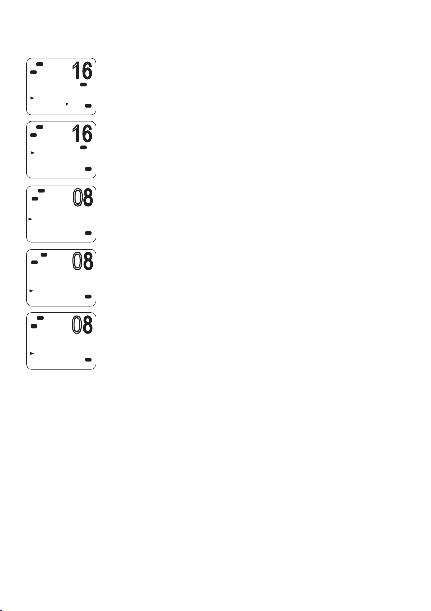
Sending an individual DSC call
1. Select DSC MENU → INDIVIDUAL.
2. Select the priority level: ROUTINE, SAFETY or URGENCY.
PRI
3. Select the buddy you want to call from the list, or
USA
• Select MANUAL NEW and enter the MMSI you want to call.
4. On the “CHOOSE CH” screen, select INTER-SHIP. (Or, select MANUAL
PRI
USA
PRI
A
USA
USA
USA
USA
to use a duplex channel—see point 2 of “General usage” on page
51.)
The display shows “SET INTER”
5. Use ▲ or ▼ to reach the working channel you want to specify and
press [OK].
6. When the SEND prompt appears.
• Press [OK] to send the call request on CH70, or
• Press [X] to exit without sending.
7. When you hear the acknowledgement alert tone,
• Press the [SILENC] softkey to silence the alert.
• Press [PTT] to commence voice communication.
8. If there is no reply within 30 seconds, the display shows: “SEND
AGAIN?”
You can then select:
• [YES] to send again, or
• [NO] to quit and return to standby mode.
¼ Note: For information on receiving an individual DSC call, see
“Receiving a DSC individual call” on page 65.
52 |
DSC procedures | V90 Operating Manual
Page 53

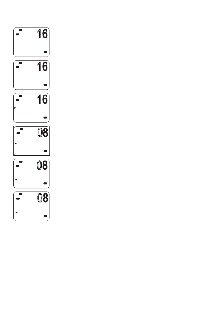
Calling the MMSI of the last call received
16
16
08
08
08
(This will send a ROUTINE, INDIVIDUAL call.)
Hi
DSC
C
DSC C ALL
INDIVIDUA L
LAST C ALL
GROUP
ALL SHIPS
Hi
DSC
C
SUNBIRD
INDIVIDUA L
ROUTINE
05:00
Lo
DSC
C
CHOOSE CH:
INTER-SHIP
MANUA L
Lo
DSC
C
SUNBIRD
INDIVIDUA L
ROUTINE
SET INTER
Lo
DSC
C
SUNBIRD
INDIVIDUA L
ROUTINE
SEND?
1. Select DSC MENU → LAST CALL.
2. The display shows the details of the most recent incoming call.
PRI
3. Press [OK] to display the “CHOOSE CH” screen.
USA
4. On the “CHOOSE CH” screen, select INTER-SHIP. (Or, select MANUAL
to use a duplex channel—see point 2 of “General usage” on page
PRI
51.)
The display shows “SET INTER”
USA
5. Use ▲ or ▼ to reach the working channel you want to specify and
press [OK].
6. When the SEND prompt appears.
USA
• Press [OK] to send the call request on CH70, or
• Press [X] to exit without sending.
7. When you hear the acknowledgement alert tone
• Press the [SILENC] softkey to silence the alert.
USA
• Press [PTT] to commence voice communication.
8. If there is no reply within 30 seconds, the display shows: “SEND
AGAIN?”
You can then select:
USA
• [YES] to send again, or
• [NO] to quit and return to standby mode.
DSC procedures | V90 Operating Manual
| 53
Page 54
Sending a group call
16
16
08
08
08
Lo
Hi
DSC
C
DSC C ALL
INDIVIDUA L
LAST C ALL
GROUP
ALL SHIPS
Hi
DSC
C
GROUP
MYGROUP1
MYGROUP2
Lo
DSC
C
CHOOSE CH:
INTER-SHIP
MANUA L
Lo
DSC
C
MYGROUP1
GROUP C ALL
SET INTER
Lo
DSC
C
MYGROUP1
GROUP C ALL
SEND?
A group MMSI is a shared MMSI. When a DSC call is transmitted by
one of the vessels in the group, all the radios that have the same
PRI
A
USA
MMSI entered will receive the message, and can reply on the chosen
channel if necessary.
To enter a group MMSI, see “Creating a group MMSI” on page 85.
¼ Notes:
PRI
USA
• Unlike the DSC or ATIS MMSI, a group MMSI can be changed at
any time.
• Group calls are always sent with ROUTINE priority.
• No DSC acknowledgement is required for a group call.
1. Select DSC MENU → GROUP.
USA
2. The display shows the names of your pre-programmed groups.
3. Select the group that you want to call.
4. On the “CHOOSE CH” screen, select INTER-SHIP. (Or, select MANUAL
to use a duplex channel—see point 2 of “General usage” on page
USA
51.)
The display shows “SET INTER”
5. Use ▲ or ▼ to reach the working channel you want to specify and
press [OK].
USA
6. When the SEND prompt appears.
• Press [OK] to send the call request on CH70, or
• Press [X] to exit without sending.
54 |
¼ Note: For information on receiving a group call, see “Receiving a DSC
group call” on page 66.
DSC procedures | V90 Operating Manual
Page 55

16
Hi
16
08
16
16
DSC
C
DSC C ALL
INDIVIDUA L
LAST C ALL
GROUP
ALL SHIPS
Hi
DSC
C
ALL SHIPS
SAFETY
URGENCY
Lo
DSC
C
CHOOSE CH:
INTER-SHIP
MANUA L
Lo
Hi
DSC
C
ALL SHIPS
SAFETY
SET INTER
Sending an all ships call
1. Select DSC MENU → ALL SHIPS.
PRI
2. Select one of the two call priorities:
USA
PRI
USA
USA
PRI
USA
• SAFET Y
Use to send safety information to all ships within range.
• URGENCY
Use when a serious situation or problem arises that could lead to
a distress situation.
3. On the “CHOOSE CH” screen, select INTER-SHIP. (Or, select MANUAL
to use a duplex channel—see point 2 of “General usage” on page
51.)
The display shows “SET INTER”
4. Use ▲ or ▼ to reach the working channel you want to specify and
press [OK].
5. When the SEND prompt appears,
• Press [OK] to send the call request on CH70, or
• Press [X] to exit without sending.
Lo
Hi
DSC
C
ALL SHIPS
SAFETY
SEND?
¼ Note: For information on receiving an all-ships call, see “Receiving a
DSC all-ships call” on page 66.
PRI
USA
Call logs
The call logs store details of the DSC calls as follows:
Call type Description
Last call Details of the last incoming call
Call log Details of the last 20 incoming calls
(does not include distress calls)
Distress log Details of the last 20 distress calls received
Sent calls log Details of the last 20 sent calls
You can use the call logs to call back a vessel that sent a call.
DSC procedures | V90 Operating Manual
| 55
Page 56
16
Hi
16
16
08
08
08
DSC
C
02 SUNBIRD
INDIVIDUA L
ROUTINE
05:00
Hi
DSC
C
02 SUNBIRD
INDIVIDUA L
ROUTINE
05:00
Hi
DSC
C
02 SUNBIRD
CALL BACK
DELETE
Lo
DSC
C
CHOOSE CH:
INTER-SHIP
MANUA L
Lo
DSC
C
SUNBIRD
INDIVIDUA L
ROUTINE
SET INTER
Lo
DSC
C
SUNBIRD
INDIVIDUA L
ROUTINE
SEND?
Calling using the call log
The call log contains the contact details for the 20 most recent
incoming calls, so that you can call one of them back quickly.
1. Select DSC MENU → CALL LOG.
USA
USA
USA
USA
USA
USA
The display shows the details of the most recent call.
2. Use ▲ and ▼ to find the caller you want to call back and press [OK].
3. Choose the option:
• CAll BACK — to send a DSC call request, or
• DELETE — to delete the call from the call log.
4. On the “CHOOSE CH” screen, select INTER-SHIP. (Or, select MANUAL
to use a duplex channel—see point 2 of “General usage” on page
51.)
The display shows “SET INTER”
5. Use ▲ or ▼ to reach the working channel you want to specify and
press [OK].
6. When the SEND prompt appears,
• Press [OK] to send the call request on CH70, or
• Press [X] to exit without sending.
7. When you hear the acknowledgement alert tone,
• Press the [SILENC] softkey to silence the alert.
• Press [PTT] to commence voice communication.
8. If there is no reply within 30 seconds, the display shows: “SEND
AGAIN?”
You can then select:
• [YES] to send again, or
• [NO] to quit and return to standby mode.
56 |
DSC procedures | V90 Operating Manual
Page 57

Calling using the distress log
16
16
16
The Distress Log contains the Distress Log data for the 20 most
recently received distress calls, so that you can call any of them
quickly. Always try to make voice contact on CH16 first, as follows:
Hi
DSC
C
DSC C ALL
GROUP
ALL SHIPS
CALL LOG
DISTR LOG
Hi
DSC
C
01 RENA
DISTRESS
UNDEFINED
CANCEL
OK-->OPTION
Hi
DSC
C
RENA
CALL BACK
DELETE
SAV E MMSI
INFO
1. Select DSC MENU → DIST LOG.
The display shows the details of the most recent call.
PRI
2. Use ▲ and ▼ to find the caller you want to call back and press [OK].
USA
3. Choose CALL BACK — to send a call request.
Other options are:
PRI
• DELETE — to delete the call from the distress log.
• SAVE MMSI — to save the caller’s MMSI.
USA
• INFO — to view more information about the distress call.
4. On the “CHOOSE CH” screen, select INTER-SHIP. (Or, select MANUAL
PRI
to use a duplex channel—see point 2 of “General usage” on page
51.)
USA
The display shows “SET INTER”
5. Use ▲ or ▼ to reach the working channel you want to specify and
press [OK].
6. When the SEND prompt appears,
• Press [OK] to send the call request on CH70, or
• Press [X] to exit without sending.
7. When you hear the acknowledgement alert tone,
• Press the [SILENC] softkey to silence the alert.
• Press [PTT] to commence voice communication.
8. If there is no reply within 30 seconds, the display shows: “SEND
AGAIN?”
You can then select:
• [YES] to send again, or
• [NO] to quit and return to standby mode.
DSC procedures | V90 Operating Manual
| 57
Page 58
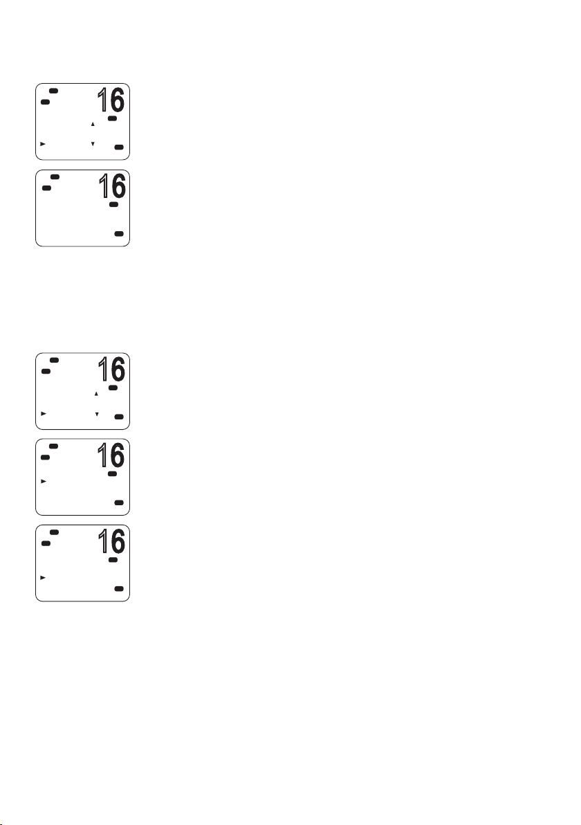
Viewing the sent call log
16
16
16
16
16
Hi
DSC
C
DSC C ALL
ALL SHIPS
CALL LOG
DISTR LOG
SENT C ALL
Hi
DSC
C
01 KITTIWAKE
INDIVIDUA L
ROUTINE
05:00
Hi
DSC
DSC C ALL
CALL LOG
DISTR LOG
SENT C ALL
LL REQUEST
Lo
Hi
DSC
LL REQUEST
SUNBIRD
KITTIWAKE
AXIOM
Hi
DSC
SUNBIRD
LL REQUEST
SEND?
The Sent Call log contains details for the 20 most recent calls sent
from your radio.
PRI
USA
You can review details of each call, and delete calls from the list as
required.
1. Select DSC MENU → SENT CALL.
The first entry in the call log is the most recent sent call.
PRI
2. Press ▲ or ▼ to scroll through the sent calls.
USA
3. With a particular call displayed, press [OK] to display the DELETE
prompt.
• Press DELETE to delete the entry from the sent call log, or
• Press [X] to exit without deleting.
Sending an LL request for the position of a buddy
The latitude and longitude request (LL request) function allows
you to send a DSC request to an MMSI on your buddy list and the
PRI
USA
PRI
USA
PRI
A
USA
response will contain the current latitude and longitude position
of the other vessel. In this way, you can check the location of your
buddy. This is also known as a “polled position request.”
¼ Note: You must first set up details of your buddy in the buddy list
(see “Buddy list setup” on page 75).
1. Press DSC MENU → LL REQUEST.
2. Select the buddy whose LL position you want to request.
3. When the “SEND?” prompt appears, press [OK] to send the LL
request.
4. If the buddy radio responds with a position, the V90 beeps.
• Press the [SILENC] softkey to silence the alert.
• Press ▲ or ▼ to view the LL information received.
58 |
5. If there is no reply within 30 seconds, the display shows: “SEND
AGAIN?”
You can then select:
• [YES] to send again, or
• [NO] to quit and return to standby mode.
DSC procedures | V90 Operating Manual
Page 59
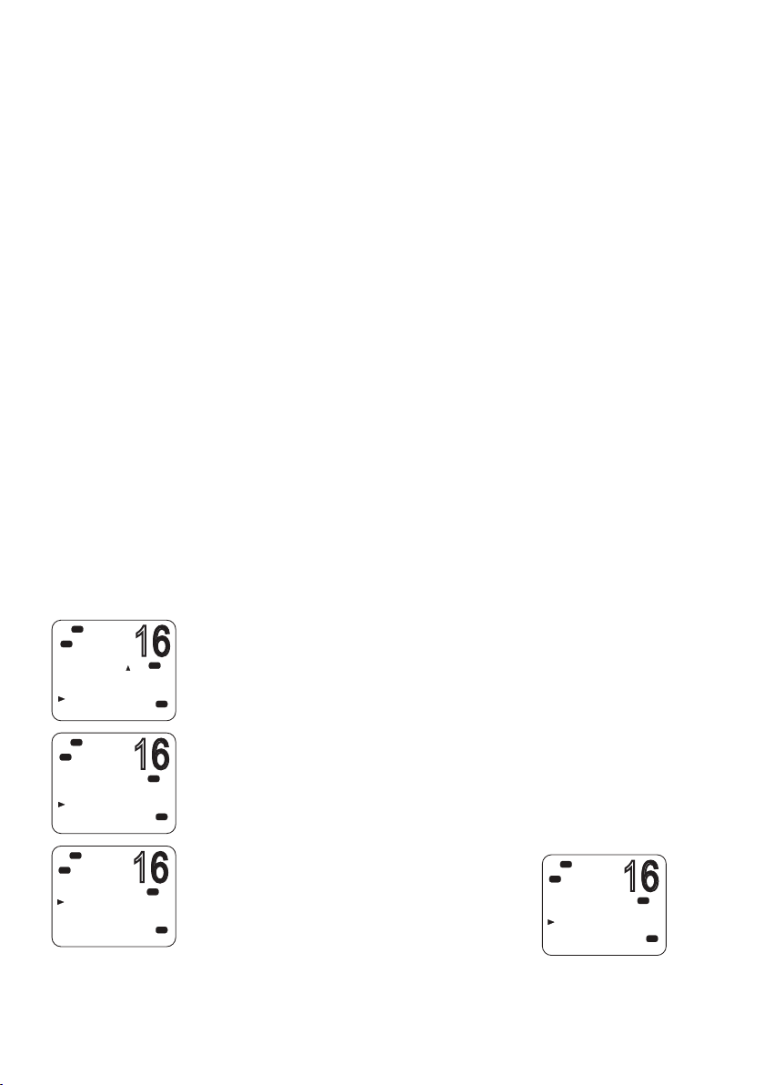
Tracking a buddy - introduction
16
16
16
16
You can select a buddy or list of buddies continuously track their
positions.
You can also start and stop tracking your buddy and add or remove
buddies from your buddy track list.
The radio sends an LL Request to each buddy in turn at a set time
interval and, if a response is received from a buddy, it displays the
buddy’s LL position on screen.
To set up buddy tracking, you need to:
1. Setup your buddies list. See “Buddy list setup” on page 75.
2. Create a tracking list of up to three buddies.
3. Set the tracking interval.
4. Select a buddy to track.
5. Start/stop tracking the buddy.
Steps 2 to 5 are explained below.
¼ Note: You can also send an individual DSC latitude and longitude
request to a buddy. See “Sending an LL request for the position of a
buddy” on page 58.
Hi
DSC
C
DSC C ALL
DISTR LOG
SENT C ALL
LL REQUEST
TRACK BUDD
Hi
DSC
C
TRACK BUDDY
STA RT TRACK
SET BUDDY
TRACKLIST
INTERVAL
Hi
DSC
C
TRACKLIST
ADD NEW
Creating your tracking list
1. Select DSC MENU → TRACK BUDDY.
PRI
2. Select TRACKLIST. Any buddies already on the tracking list will be
USA
PRI
USA
PRI
A
USA
listed.
3. To add a buddy to the tracking list, select ADD NEW to show your
list of buddies.
4. Select a buddy then press [OK] to add that buddy to the tracking list.
To delete a buddy from the tracking list:
Select that buddy then press [OK].
• Select YES to delete, or
• NO to keep the buddy in the list.
¼ Note: The tracking list is limited to
Hi
DSC
C
DEL TRKBUDDY
BLUEBIRD
YES
NO
three buddies.
DSC procedures | V90 Operating Manual
PRI
USA
| 59
Page 60

16
Hi
16
16
16
16
16
16
DSC
C
DSC C ALL
DISTR LOG
SENT C ALL
LL REQUEST
TRACK BUDD
Setting the track buddy update interval
You can set the interval at which the position requests are sent out.
1. Select DSC MENU → TRACK BUDDY.
PRI
2. Select INTERVAL.
USA
3. Select the required interval: 15, 30 or 60 minutes.
Hi
DSC
C
TRACK BUDDY
STA RT TRACK
SET BUDDY
TRACKLIST
INTERVAL
Hi
DSC
C
INTERVAL
15 MIN
30 MIN
1 HOUR
Hi
DSC
C
DSC C ALL
DISTR LOG
SENT C ALL
LL REQUEST
TRACK BUDD
Lo
Hi
DSC
C
TRACK BUDDY
STA RT TRACK
SET BUDDY
TRACKLIST
INTERVAL
Hi
DSC
C
SET BUDDY
BLUEBIRD
KITTIWAKE
OF F
OF F
4. Press [OK].
PRI
USA
PRI
USA
Selecting a buddy to track
1. Select DSC MENU → TRACK BUDDY.
2. Select SET BUDDY to show the tracking status of each buddy on
PRI
USA
PRI
A
USA
USA
your tracking list.
3. Select the buddy whose status you want to change.
4. Select ON or OFF as required to change the tracking status and press
[OK] to confirm.
60 |
Hi
DSC
C
SET BUDDY
BLUEBIRD
ON
OFF
PRI
USA
DSC procedures | V90 Operating Manual
Page 61

16
Hi
16
16
16
DSC
C
DSC C ALL
DISTR LOG
SENT C ALL
LL REQUEST
TRACK BUDD
Lo
Hi
DSC
C
TRACK BUDDY
STA RT TRACK
SET BUDDY
TRACKLIST
INTERVAL
Hi
DSC
C
START TRACK
BLUEBIRD
KITTIWAKE
Hi
DSC
C
STA RT TRACK
YES
NO
ON
OF F
Start or stop tracking a Buddy
Note: START TRACK will only track buddies on your TRACKLIST whose
PRI
USA
PRI
USA
USA
PRI
USA
status is ON.
1. Select DSC MENU → TRACK BUDDY.
2. Select START TRACK.
The display shows the status of each buddy on your tracking list (ON
or OFF).
3. Check that the status of the buddies that you want to track is ON,
and then press [OK].
4. When prompted:
• Select YES to start tracking, or
• NO to STOP tracking.
The radio sends an LL Request to each buddy in turn at the interval
time and, if a response is received from a buddy, displays the
buddy’s LL position on screen.
For information on receiving a response to an LL request, see
“Receiving a response to a DSC LL request” on page 67.
DSC procedures | V90 Operating Manual
| 61
Page 62
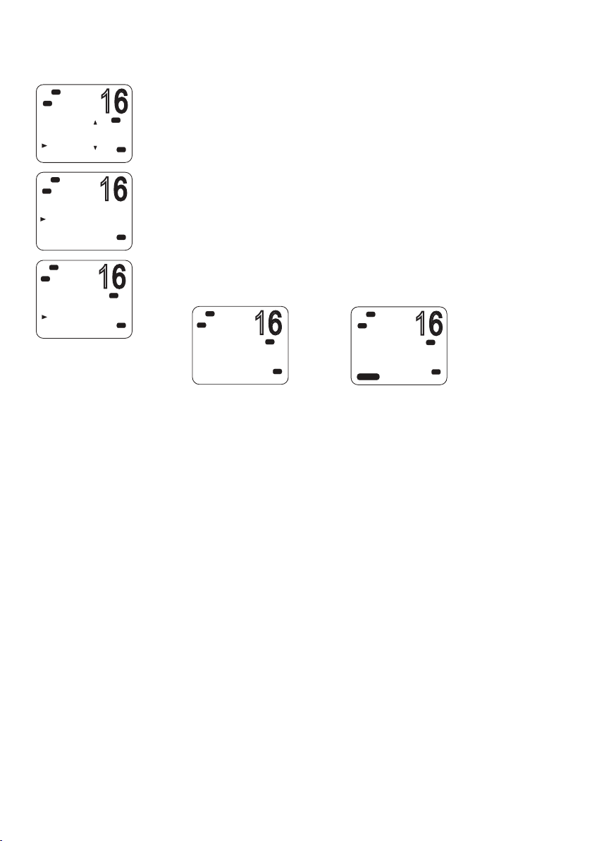
Sending a DSC test call
16
16
16
16
16
Hi
DSC
C
DSC CALL
SENT CALL
LL REQUEST
TRACK BUDDY
DSC TEST
Hi
DSC
C
DSC TEST
MANUA L NEW
SUNBIRD
KITTIWAKE
WANDERER
Hi
DSC
C
SUNBIRD
DSC TEST
SEND?
To make sure DSC is working correctly, you can send a test call to a
buddy or any other station equipped with a DSC radio.
PRI
1. Select DSC MENU → DSC TEST.
2. Select a buddy from your buddy list, or select MANUAL NEW to
USA
enter the MMSI you want to call.
3. When the SEND prompt appears,
A
USA
• Press [OK] to send the request on CH70, or
• Press [X] to exit without sending.
4. When you hear the acknowledgement alert tone,
PRI
USA
• Press the [SILENC] softkey to silence the alert.
Hi
DSC
C
SUNBIRD
DSC TEST
WAIT..00:10
X-->EXIT
PRI
USA
Hi
DSC
C
TEST
ACK FROM
SUNBIRD
--:--
SILENC
00:10
PRI
USA
5. If there is no reply within 30 seconds, the display shows: “SEND
AGAIN?”
You can then select:
• [YES] to send again, or
• [NO] to quit and return to standby mode.
62 |
¼ Note: For information on receiving a DSC test call, see “Receiving a
DSC test call” on page 68.
DSC procedures | V90 Operating Manual
Page 63
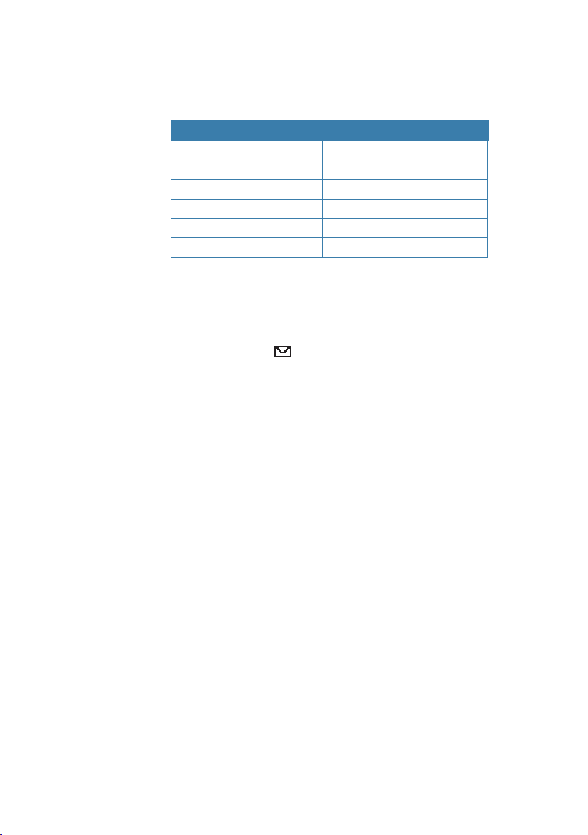
Receiving DSC calls
Several types of DSC calls can be received from vessels or coast
stations within range:
Call type Page
Distress page 65
Individual page 65
All ships page 65
Group page 66
Geographic page 67
DSC test call page 68
General process
When the radio receives a DSC call, it does several things as follows:
• Sounds the alert tone to notify you of the call.
• Displays a flashing
has been received and stored in the call log. When all call in the call
log and distress log have been viewed, the icon stops flashing. For
information on call logs, see “Calling using the call log” on page
56.
• Displays the MMSI (or name) of the calling station. You can press
▲ and ▼ to view more details of the call, including the requested
working channel.
• For individual calls, displays “AUTO SWITCH” or “NO AUTO SW,”
depending on the INDIV REPLY setting. It will automatically or
manually send an an acknowledgement to the calling radio and
switch to the requested channel.
• For Group or All-Ships calls, displays “AUTO SWITCH” or “NO AUTO
SW,” depending on the Auto Switch setting.
icon on screen, which indicates that a call
With Auto Switch set to ON, when receiving a Group or All-Ships
call, the radio will automatically switch to the requested channel
if not cancelled within 10 seconds. This might disrupt important
communications that are already in progress on the current working
channel. To avoid this, you can prevent the radio from automatically
switching channel by setting the AUTO SWITCH option to OFF.
For information on setting the auto switch option, see “Automatic
channel switch options” on page 88.
The procedures for receiving calls with Auto Switch either on or off
are described below.
DSC procedures | V90 Operating Manual
| 63
Page 64

AUTO SWITCH
16
16
16
16
16
08
DSC
C
ALL SHIP
SAFETY FROM
SUNBIRD
AUTO SWIT CH
SILENC
DSC
C
ALL SHIP
SAFETY FROM
SUNBIRD
AUTO SWIT CH
ACCEPT
DSC
C
D
INDIVIDUA L
ROUTINE FROM
SUNBIRD
NO AUTO S W
SILENC
DSC
C
INDIVIDUA L
ROUTINE FROM
SUNBIRD
NO AUTO S W
NEW-CH ABLE
DSC
C
ROUTINE FROM
SUNBIRD
NO AUTO S W
CH09 REQUEST
NEW-CH ABLE
DSC
C
INDIV ACK
CHANGE CHAN
SET CHANNEL
ABLE
64 |
Lo
Hi
Hi
L
Hi
CNS
Hi
Hi
CIS
Lo
01:15
00:08
01:15
01:15
01:15
(For Group or All-ships calls with AUTO SWITCH set to ON)
When the radio sounds the incoming DSC call alert:
PRI
1. Press the [SILENC] softkey to silence the alert.
USA
2. To see more details about the call, including the requested channel,
press ▲ or ▼.
3. You now have the following three options:
PRI
• Press [ACCEPT] to switch to the requested channel immediately,
USA
or
• Do nothing to allow the radio to automatically switch after 10
seconds, or
• Press [X] to cancel the automatic switch and remain on the
current channel.
4. When needed, press [PTT] to talk on the selected working channel.
AUTO ACK
(For Individual calls with INDIV REPLY set to Auto)
PRI
ASU
PRI
PRI
ASU
USA
When the radio sounds the incoming DSC call alert:
1. Press the [SILENC] softkey to silence the alert.
2. To see more details about the call, including the requested channel,
press ▲ or ▼.
3. You can then use one of the following three softkeys:
• [ABLE]
Acknowledge the call on the requested channel.
The radio will send the acknowledge signal and change to the
designated channel.
• [NEW-CH]
Acknowledge the call, but request a different channel:
• Press ▲ or ▼ to reach the channel you want to use, and then
press the [ABLE] softkey.
The radio will send a request for your preferred channel.
¼ Note: AUTO ACK is not allowed in some EU countries.
• [UNABLE]
Acknowledges the call, but signals that you are unable to use the
requested channel.
DSC procedures | V90 Operating Manual
Page 65

L
CNS
16
16
16
Hi
DSC
C
D
INDIVIDUA L
ROUTINE FROM
SUNBIRD
NO AUTO S W
01:15
SILENC
Hi
DSC
C
INDIVIDUA L
ROUTINE FROM
SUNBIRD
NO AUTO S W
01:15
NEW-CH ABLE
¼ Note: this option is not available for ROUTINE calls. If INDIV REPLY is
set to AUTO, the radio will automatically send an acknowledgement
to the caller if there is no user intervention within 10 seconds.
• When needed, press [PTT] to talk on the selected working
channel.
Receiving a DSC distress call
See “DSC distress calls” on page 47.
Receiving a DSC individual call
When the radio receives a DSC call, it sounds the alert tone for 2
PRI
ASU
PRI
minutes and displays the priority level and the calling MMSI (or
buddy name).
1. Press the [SILENC] softkey to silence the alert.
2. Press ▲ or ▼ to view further information about the call, including
the channel requested, or
• Press [X] to exit without acknowledging.
3. Use the procedures described in “AUTO ACK” on page 64 to
acknowledge the call, depending on your radio’s INDIV REPLY
settings.
4. The radio will send an acknowledge signal to the calling station.
Hi
DSC
C
INDIV ACK
SENT T O
SUNBIRD
RE-ACK
01:15
The radio displays the elapsed time since the incoming call (prior
to acknowledgment); or the elapsed time since acknowledgement
(after acknowledgment).
PRI
5. Press the RE-ACK softkey to send the acknowledgement at any time.
USA
6. The caller should respond to your acknowledgement by making
voice contact on the designated channel. If not, you can press PTT
to initiate voice contact yourself.
¼ Notes:
• The call data is stored in your Call Log (see “Calling using the call log”
on page 56).
• For information on sending a DSC individual call, see “Sending an
individual DSC call” on page 52.
DSC procedures | V90 Operating Manual
| 65
Page 66
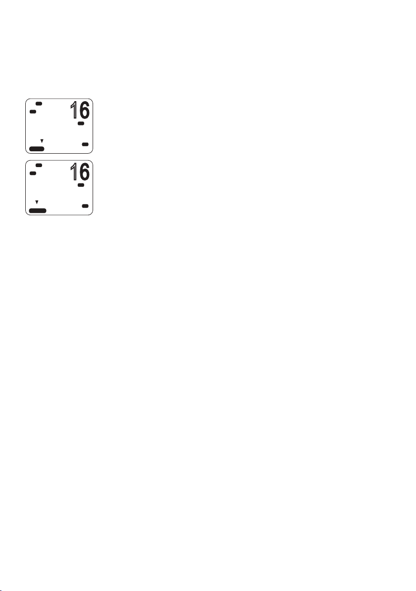
Receiving a DSC all-ships call
16
16
When the radio receives a DSC call, it sounds the alert tone for 2
minutes and displays the priority level and the calling MMSI (or
buddy name).
Lo
Hi
DSC
C
ALL SHIP
SAFETY FROM
SUNBIRD
AUTO SWIT CH
01:15
SILENC
Hi
DSC
C
ALL SHIP
SAFETY FROM
SUNBIRD
AUTO SWIT CH
00:08
ACCEPT
1. Press the [SILENC] softkey to silence the alert.
2. Press ▲ or ▼ to view further information about the call, including
PRI
USA
the channel requested, or
• Press [X] to exit without acknowledging.
3. Use the procedures described in “AUTO SWITCH” on page 64
to acknowledge the call, depending on your radio’s auto switch
PRI
USA
settings.
4. If appropriate, press PTT to talk on the currently displayed channel.
¼ Notes:
• The call data will be stored in your Call Log (see “Calling using the
call log” on page 56).
• For information on sending a DSC all-ships call, see “Sending an all
ships call” on page 55.
Receiving a DSC group call
When a DSC call is transmitted by one of the vessels in a group,
all the radios that have the same MMSI entered will receive the
message.
When the radio receives a DSC group call, it sounds the alert tone
for 2 minutes and displays the priority level (ROUTINE for a group
call) and the calling MMSI (or group name).
66 |
The radio may change to the requested channel depending on the
AUTO SWITCH setting.
1. Press the [SILENC] softkey to silence the alert.
2. Press ▲ or ▼ to view further information about the call.
3. You do not need to send an acknowledgement.
4. If appropriate, press PTT to talk on the designated channel.
DSC procedures | V90 Operating Manual
Page 67

¼ Notes:
• The call data is stored in your Call Log (see “Call logs” on page 55).
• For information on setting up your group MMSIs see “Creating a
group MMSI” on page 85.
• For further information, see “Sending a group call” on page 54.
Receiving a DSC geographic area call
A geographic call is received by vessels within a specific geographic
boundary area. The display shows the calling MMSI (or buddy
name).
When you receive notification of a GEOGRAPHIC call:
1. Press the [SILENC] softkey to silence the alert.
2. Press ▲ or ▼ to view further information about the call, including
the channel requested.
3. Listen to the working channel for an announcement from the calling
station.
Receiving a response to a DSC LL request
When you receive GPS data from a buddy in response to your LL
request you should make a written note of the position.
1. Press [SILENC] softkey to silence the alert.
2. Press ▲ or ▼ view further information about the call.
3. When finished, press [X].
¼ Notes:
• To send an LL request, see “Sending an LL request for the position of
a buddy” on page 58.
• LL request data is not stored on the V90.
DSC procedures | V90 Operating Manual
| 67
Page 68

Receiving a DSC test call
You can set up the radio to respond to incoming DSC TEST calls with
an automatic response or manual response. To change the option,
see “Setting up DSC test reply” on page 89.
Manual response
1. On receiving a DSC test request, the radio sounds a two-tone alert.
2. Press the [SILENC] softkey to silence the alert.
3. Press the [ACK] softkey to acknowledge the DSC Test Call.
Auto response
• On receiving a DSC test request, the radio automatically replies after
a 10 second delay with an ACK signal.
68 |
DSC procedures | V90 Operating Manual
Page 69

ATIS
EU models only.
The Automatic Transmitter Identification System (ATIS) is
mandatory for vessels navigating on some European waterways.
The system allows authorities to monitor and regulate VHF radio
communications by identifying any vessel that makes a VHF
transmission. Each vessel is required to have an ATIS-enabled radio
on board and is allocated a unique ATIS Maritime Mobile Service
Identity (MMSI).
Each time a radio operator finishes talking and releases the PTT key,
the radio transmits a short digital message, which includes the ATIS
MMSI. The receiving station can then look up details of the vessel,
saving time in communication on the busy VHF channels.
Unlike DSC, the ATIS signal is transmitted on the same VHF channel
as the voice transmission.
Before you can enable ATIS, you must enter the ATIS MMSI. See
“Entering or checking your ATIS MMSI” on page 86.
Before you can enable ATIS, DSC must be turned off. See ”Enabling
DSC functionality” on page 87. To enable ATIS, see “Enabling ATIS
functionality” on page 86.
¼ Notes:
• ATIS is disabled in US models.
• When ATIS is enabled, the ATIS icon appears on screen.
• In some European countries SCAN functionality is limited, and, if ATIS
is enabled, the 3CH SCAN and Dual scan modes will be disabled.
DSC procedures | V90 Operating Manual
| 69
Page 70

7
AIS procedures
The marine Automatic Identification System (AIS) is a vessel location
and information reporting system. It allows vessels to automatically
share information such as position, speed, course and identity via a
VHF radio link.
The received details of nearby vessels can be displayed on the
handset screen together with closest point of approach times and
distances. These details are also sent to the NMEA ports for display
on a chart plotter if one is connected.
Closest point of approach (CPA) is the calculated closest distance
between your vessel and a target vessel based on the current speed
and course.
Time to closest point of approach (T/CPA) is the calculated time for a
target vessel to arrive at the closest point of approach based on the
current speed and course. If the radio detects that another vessel
will come closer than the set CPA distance and within the set T/CPA
time, the CPA alarm will sound. Both conditions must be met for the
CPA alarm to sound.
For information on enabling AIS and setting the CPA time and
distance criteria, see “AIS setup” on page 91.
For general information about AIS, see “Appendix 9 - AIS
information” on page 108.
70 |
For information on how to configure your chart plotter or software
to make use of the V90 AIS data, see the manual provided with that
product.
¼ Notes:
• Before the AIS functions can be used, the V90 must receive its own
position from a GPS device, or manually entered data.
• The V90 VHF radio includes an AIS receiver but does not transmit.
To access the AIS displays:
• Press [AIS]
• Repeat press [AIS] to switch between the three available displays:
MMSI list (list of nearby vessels)
PPI display
T/CPA list
From any of the above displays, you can select an MMSI to display
details about the particular vessel.
AIS procedures | V90 Operating Manual
Page 71
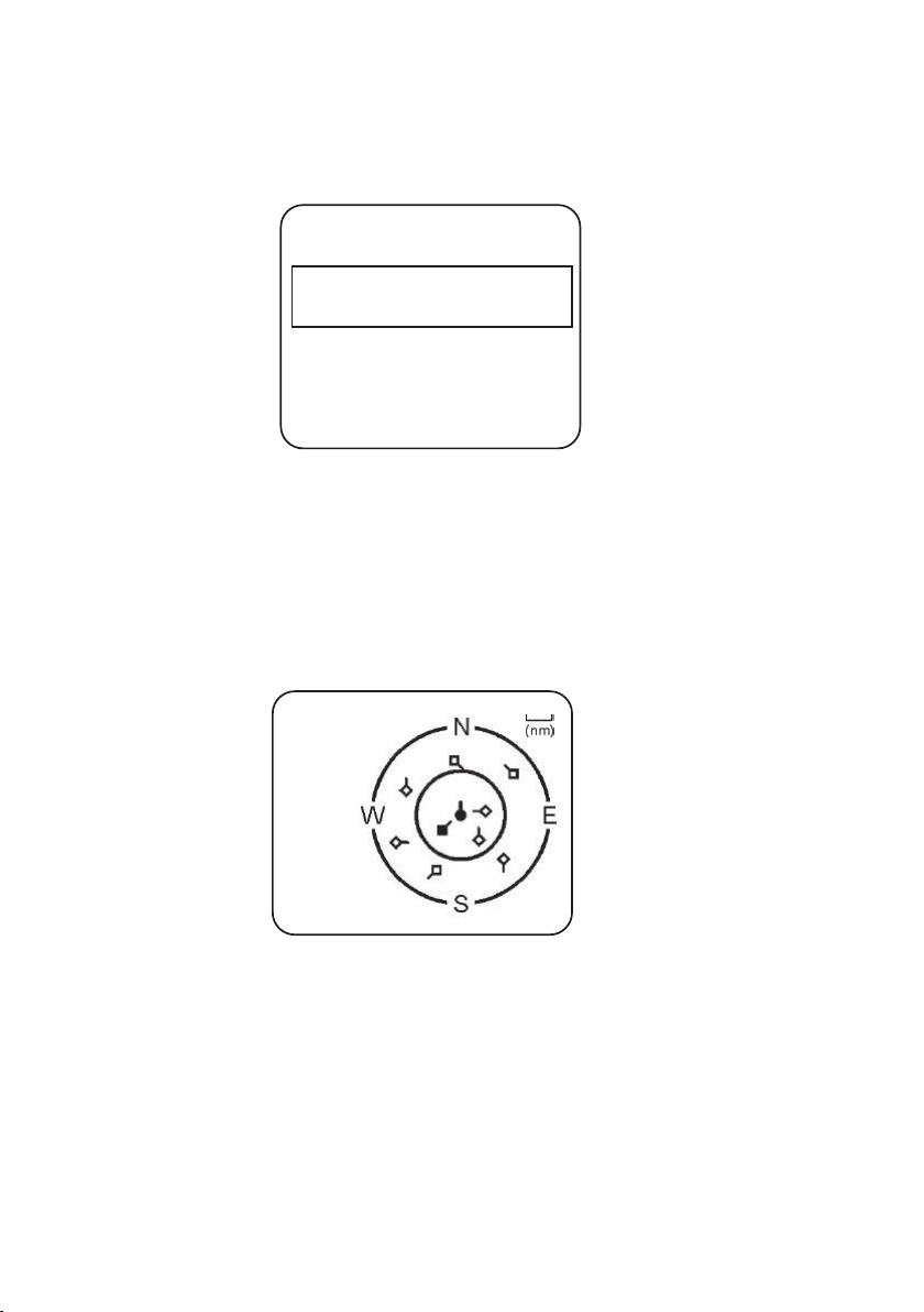
List of nearby vessels
The MMSI list displays a list of vessels within VHF range.
The list is arranged in ascending order; closest first.
8nMMMSI LIST 1/2
1 SEASPRAY
225 0.59nM
2 SUNBIRD
275 1.43nM
Each vessel’s MMSI (or name, depending on AIS setup) will be
displayed, together with its bearing and distance from your position.
PPI display
The Plan Position Indicator (PPI) shows the geographical location of
AIS targets with respect to your position, which is represented in the
centre of the circular display.
AIS CHART 1/9 8
Symbols
• The solid circle in the middle is your vessel.
• Hollow diamonds represent vessels that are within the current
zoom distance.
• The solid diamond is the selected target vessel.
• The tails represent course over ground.
¼ Note: Units on the PPI display are always nautical miles.
AIS procedures | V90 Operating Manual
| 71
Page 72

To zoom in or out:
• Press [3CH] to zoom in.
• Press [Scan] to zoom out.
Scales available are 1nm / 2 nm / 4 nm / 8 nm / 16 nm / 32 nm.
T/CPA screen
The Time and Closest Point of Approach (T/CPA) screen shows the
closest point of approach settings together with a list of vessels that
will approach within those criteria.
• CPA alert distance is set up in MENU → AIS SETUP → CPA. (See
“Setting up the CPA distance” on page 92.)
• T/CPA alert time is set up in MENU → AIS SETUP → TCPA. (See
“Setting up the T/CPA time” on page 93.)
The approaching AIS target’s details will be listed on the left of the
screen.
Once the vessel is within alert distance (CPA) and time (T/CPA), it will
be placed in the T/CPA list.
The alert sounds for every vessel within the criteria every time their
AIS signal is received.
72 |
T/CPA APPROACH
1/ 9 05:00 min 8 nM
• In the example above, the criteria are: 5:00 min and 8 nM.
¼ Notes:
• The scale on the T/CPA Approach screen is automatically set to the
optimum for the selected target. You cannot zoom in or out on this
screen.
• If the radio detects a T/CPA or CPA breach, the T/CPA Approach
screen will automatically popup with an alert tone. Press [X] to stop
the alert; otherwise, the alert will sound again after 1 minute.
AIS procedures | V90 Operating Manual
Page 73

AIS target information
From one of the AIS screens, you can display available detailed
information about a target vessel:
1. Press ▲ or ▼ to highlight the required target. (Hold down ▲ or ▼
to scroll rapidly.)
2. Press [OK] to view full details of the selected target, including:
• NAME:
MMSI:
TCPA: 4:39 s
CPA: 0.59nM
WIDTH: 26.0m
LENGTH: 158.0m
RECEIVED: 0m33s
CALL SIGN: MYHV6
DRAU GH T:
DIS T: 1.01nM
IMO:
BEAR: 155’
HEADING:
ROT: 72 5 . 6’/min
SOG: 0.0KTS
COG: 0.0’ 55’51.240’N, 012’49.991’E
TYPE: CARGO
NAV STATUS: NOT DEFINED
The display alternates between the first and next page every 5
seconds.
3. When finished, press [X] to exit.
AIS procedures | V90 Operating Manual
| 73
Page 74
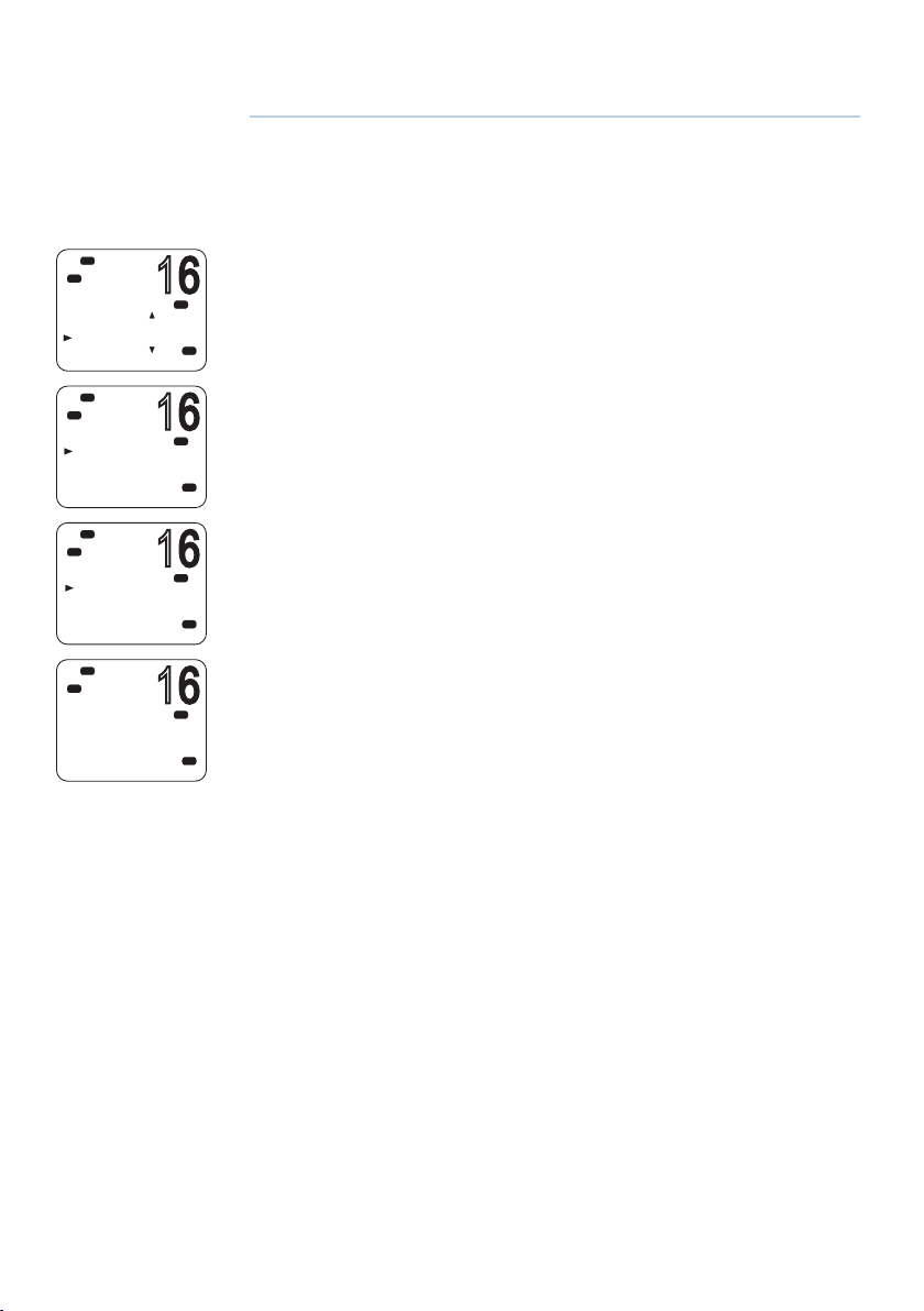
8
16
16
16
16
Hi
DSC
DSC
MENU SELECT
AIS SETUP
GPS SIM
WIRELESS HS
RESET
Hi
DSC
HS SETTING
SUBSCRIBE
REGISTERED
Lo
Hi
DSC
SUBSCRIBE
YES
NO
Hi
DSC
SUBSCRIBE
WAITING
X-->EXIT
Setup
Wireless handset setup
Subscribing a wireless handset
At installation time, wireless handsets need to be registered in the
PRI
USA
PRI
USA
PRI
A
USA
PRI
USA
V90 transceiver. Once registered, a handset automatically connects
to the transceiver when both are switched on. For information
about operating the handsets, see “Handsets” on page 16.
1. Make sure the wireless handset is charged and turned OFF.
2. Make sure any other wireless handsets are also turned OFF.
3. On the wired handset, Select MENU → WIRELESS HS → SUBSCRIBE.
4. Select YES. The radio will display WAITING.
5. Turn on the wireless handset. The display will show SEARCHING.
6. Press and hold the [SCAN] on the wireless handset until the display
shows REGISTER.
The display will soon show CONNECTING, and then the handset will
be registered in the transceiver.
74 |
Setup | V90 Operating Manual
Page 75
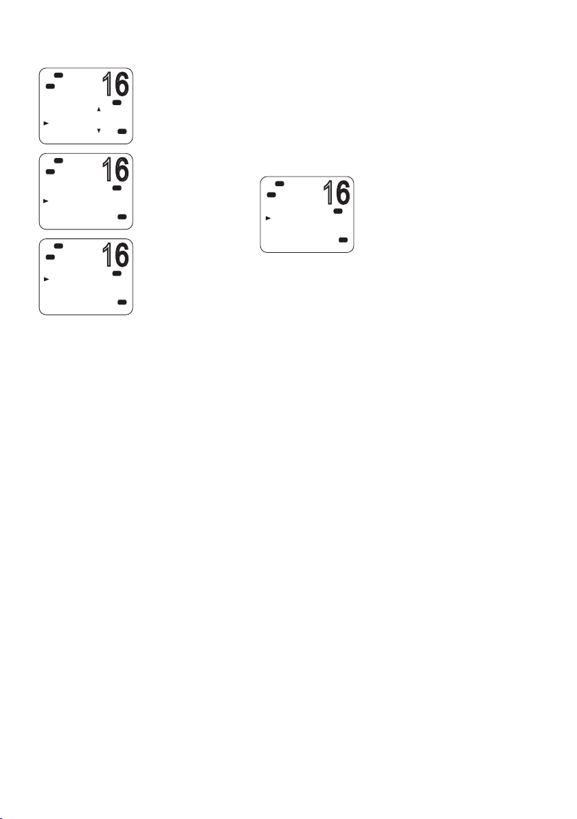
16
Hi
16
16
16
DSC
DSC
MENU SELECT
AIS SETUP
GPS SIM
WIRELESS HS
RESET
Hi
DSC
WIRELESS HS
SUBSCRIBE
REGISTERED
Hi
DSC
CLEAR
FIRST
SECOND
Unsubscribing a wireless handset
To delete an already registered handset:
PRI
1. Select MENU → WIRELESS HS → REGISTERED.
2. Select the handset you wish to remove.
USA
3. Select CLEAR <handset name>.
PRI
USA
PRI
USA
4. Select YES.
Hi
DSC
CLEAR 1ST
YES
NO
Buddy list setup
The buddy list stores up to 20 contact names and MMSIs. Contact
names are stored in the order of entry, with the most recent entry
shown first.
PRI
USA
Once set up, you can use the buddy list to:
• DSC call an individual buddy; see “Sending an individual DSC
call” on page 52.
• DSC request location of a buddy; see “Sending an LL request for
the position of a buddy” on page 58.
• DSC track selected buddies; see “Tracking a buddy -
introduction” on page 59.
• DSC Test call; see “Sending a DSC test call” on page 62.
Setup | V90 Operating Manual
| 75
Page 76
Add a new buddy
16
16
16
16
16
16
16
Hi
DSC
C
MENU SELECT
WAYPOINT
N2K D ATA
BACKLIGHT
BUDDY LIST
Hi
DSC
C
BUDDY LIST
MANUA L NEW
Hi
DSC
C
MENU SELECT
WAYPOINT
N2K D ATA
BACKLIGHT
BUDDY LIST
Hi
DSC
C
BUDDY LIST
MANUA L NEW
BLUEBIRD
KITTIWAKE
Hi
DSC
C
BLUEBIRD
EDIT
DELETE
You can enter a maximum of 20 buddy names.
1. Select MENU → BUDDY LIST → MANUAL NEW.
2. Enter the buddy name, one character at a time up to a maximum of
USA
11 alphanumeric characters.
3. Press [OK] repeatedly if necessary until the cursor moves to the
MMSI entry line.
4. Enter the MMSI number associated with the buddy name, then press
USA
[OK] repeatedly until STORE/CANCEL is displayed.
5. Scroll to STORE or CANCEL as required and then press [OK].
¼ Note: When the buddy list is full, you cannot make a new entry until
you have deleted an existing entry.
Edit or delete a buddy name
1. Select MENU → BUDDY LIS T.
2. Scroll to the required entry and press [OK].
3. To edit the buddy, select EDIT.
USA
USA
USA
• Edit the buddy name, or
• To edit only the MMSI, press [OK] repeatedly until the cursor
moves to the MMSI line.
• When finished editing, press [OK] repeatedly if necessary until
STORE/CANCEL appears.
• Scroll to STORE or CANCEL as required and then press [OK].
To delete a buddy:
• Select DELETE at step 3, and then YES. The buddy will be deleted
from the list immediately.
76 |
Hi
DSC
C
BLUEBIRD
EDIT
DELETE
USA
Setup | V90 Operating Manual
Hi
DSC
C
DELETE BUDDY
BLUEBIRD
YES
NO
USA
Page 77
Radio setup
16
16
16
16
16
16
16
Hi
DSC
MENU SELECT
LOCAL/DIST
CONTRAST
GPS/DATA
RADIO SETU
Hi
DSC
RADIO SETUP
UIC
CH NAME
RING VOLUME
KEY BEEP
Hi
DSC
UIC
‘
USA
INT L
CANADA
Hi
DSC
MENU SELECT
LOCAL/DIST
CONTRAST
GPS/DATA
RADIO SETU
Hi
DSC
RADIO SETUP
UIC
CH NAME
RING VOLUME
KEY BEEP
Lo
Hi
DSC
CH NAME
PORT OPS
Hi
DSC
PORT OPS
EDIT
DELETE
UIC
PRI
USA
PRI
USA
PRI
USA
US and AUS models only.
This option allows you to switch between USA, International, or
Canadian channel banks. The selected channel bank is displayed
on the LCD along with the last used channel. For details of channel
banks, see “Appendix 11 - US and ROW VHF marine channel charts”
on page 114.
1. Select MENU → RADIO SETUP → UIC.
2. Select the desired channel bank then press [OK].
Editing channel names
If a channel has been assigned a name, the name appears next to
the channel number on the standby screen. You can edit or delete
PRI
USA
PRI
A
USA
PRI
USA
PRI
USA
the channel names.
A list of default channel names is given in “Appendix 11 - US and
ROW VHF marine channel charts” on page 114 and “Appendix 12
- EU VHF marine channel charts” on page 122.
1. Select MENU → RADIO SETUP → CH NAME.
2. Use ▲ and ▼ to scroll to the one you want to change then press
[OK].
3. Select EDIT.
4. Enter the new name over the existing one.
5. Press [OK] repeatedly if necessary to display the YES/NO
confirmation.
6. Scroll to YES or NO as required and press [OK].
To delete a channel name:
Use a similar procedure to the above, but select DELETE at step 3.
Setup | V90 Operating Manual
| 77
Page 78
16
Hi
16
16
16
16
16
DSC
RADIO SETUP
UIC
CH NAME
RING VOLUME
KEY BEEP
Ring volume
PRI
USA
The radio sounds a two-tone alert when it detects an incoming DSC
call. You can change the volume level.
1. Select MENU → RADIO SETUP → RING VOLUME.
Hi
DSC
RING VOLUME
HIGH
LOW
Hi
DSC
RADIO SETUP
UIC
CH NAME
RING VOLUME
KEY BEEP
Hi
DSC
KEY BEEP
ON
OFF
Hi
DSC
RADIO SETUP
UNITS
EX T SPEAKER
WATC H MODE
WX ALERT
Hi
DSC
UNITS
METRIC
NAUTICA L
STATUTE
2. Scroll to HIGH or LOW as required, then press [OK].
PRI
USA
Key beep
You can change the key beep volume or turn the key beeps off
PRI
USA
completely.
1. Select MENU → RADIO SETUP → KEY BEEP.
2. Scroll to the required setting: ON or OFF, then press [OK].
¼ Note: The key beep setting is separate for each handset.
PRI
USA
Units
You can select your preferred measurement units for distance and
cross-track error (for waypoint navigation).
PRI
1. Select MENU → RADIO SETUP → UNITS.
USA
2. Scroll to the required measurement units: METRIC, NAUTICAL or
STATUTE, then press [OK].
PRI
¼ Note: Nautical Miles is the only unit available in AIS mode.
USA
78 |
Setup | V90 Operating Manual
Page 79
16
Hi
16
16
16
DSC
RADIO SETUP
UNITS
EX T SPEAKER
WATC H MODE
WX ALERT
Lo
Hi
DSC
EX T SPEAKER
ON
OFF
External speaker
You can switch the external speaker ON or OFF.
PRI
1. Select MENU → RADIO SETUP → EXT SPEAKER.
USA
2. Scroll to ON or OFF as required, and then press [OK].
PRI
A
USA
Setting the priority channel
Hi
DSC
RADIO SETUP
KEY BEEP
UNITS
EX T SPEAKER
WATC H MODE
Hi
DSC
WATC H MODE
ONLY 16CH
16CH+9CH
US model only.
If you are operating on the USA or Canadian channel banks, you can
PRI
USA
set the radio to scan CH16 and CH9 as well as the working channel.
1. Go to menu option RADIO SETUP → WATCH MODE.
2. Select one of the two options:
• 16CH to enable Channel 16 only, or
PRI
A
USA
• 16CH+9CH to enable both Channel 16 and Channel 9.
This setting affects Dual Watch and Tri watch modes.
When watch mode is only channel 16:
• The [16/9] key switches to channel 16.
• Short press [SCAN] enters dual-watch mode.
• Long press [SCAN] scans all available channels.
When watch mode is channel 16 and channel 09:
• Short press the [16/9] key switches to the current priority
channel.
• Long press the [16/9] key toggles the priority channel between
CH16 and CH09.
• Short press [SCAN] enters tri-watch mode.
• Long press [SCAN] scans all available channels.
For further information, see:
• “Priority channels” on page 25.
• “Dual watch scan” on page 36
• “Tri watch scan” on page 37
Setup | V90 Operating Manual
| 79
Page 80

Setting up a favorite channel
16
08
16
16
16
Hi
DSC
RADIO SETUP
KEY BEEP
UNITS
EX T SPEAKER
FAV CH SET
Hi
DSC
FAV CHANNEL
SELECT
SHIP SHIP
Hi
DSC
RADIO SETUP
UNITS
EX T SPEAKER
WATC H MODE
WX ALERT
Hi
DSC
WX ALERT
TONE ALER T
SAME ALER T
SAME CODE
Hi
DSC
TONE ALER T
ON
OFF
Non-US models only.
The WX key can be programmed to a channel of your choice so that
PRI
USA
you have quick access to that channel. For further information, see
“Favorite channel (non-US models)” on page 33.
1. Select MENU → RADIO SETUP → FAV CH SET.
2. Use the ▲ and ▼ keys to select the required channel, and then
PRI
USA
press [OK].
¼ Note:
• For US models, the WX key has a different purpose. See “Receiving
weather alerts (US model only)” on page 32.
• You can store just one favorite channel.
Setting up weather tone alert
US model only.
PRI
1. Select MENU → RADIO SETUP → WX ALERT → TONE ALERT.
2. Select ON or OFF as required.
USA
Tone alert ON.
• If an alert tone is broadcast from the NOAA weather station, the
PRI
USA
PRI
USA
weather alert is picked up automatically and the alarm sounds. Press
any key to cancel the alarm and to hear the weather alert message.
• The Weather alert symbol will be displayed on screen to show that
the weather alert tone setting is on.
Weather alert symbol:
Tone alert OFF
80 |
With this setting, the radio ignores weather alerts.
Setup | V90 Operating Manual
Page 81

16
Hi
16
16
16
16
16
DSC
RADIO SETUP
UNITS
EX T SPEAKER
WATC H MODE
WX ALERT
Hi
DSC
WX ALERT
TONE ALER T
SAME ALER T
SAME CODE
Hi
DSC
SAME ALER T
ON
OFF
Setting up SAME alert
US model only.
¼ Note: SAME ALERT works only after you have entered and selected a
SAME code for your geographic area (see “Entering a SAME code” on
page 81).
For usage, see “Receiving SAME alerts (US model only)” on page
PRI
USA
PRI
USA
PRI
USA
32.
1. Select MENU → RADIO SETUP → WX ALERT → SA ME ALERT.
2. Select On or OFF as required.
¼ Note: SCAN mode will operate up to 50% more slowly when SAME
ALERT is ON to allow time to decode the special warning code
transmissions.
SAME alert ON
• The radio will receive any local NWR or EAS alerts.
• The SAME icon will be displayed on screen to show that the SAME
alert setting is on.
SAME alert OFF
With this setting, the radio ignores SAME weather alerts.
Hi
DSC
RADIO SETUP
UNITS
EX T SPEAKER
WATC H MODE
WX ALERT
Hi
DSC
WX ALERT
TONE ALER T
SAME ALER T
SAME CODE
Hi
DSC
SAME CODE
NEW CODE
012011
Entering a SAME code
US model only.
PRI
USA
PRI
USA
PRI
USA
Before you can receive SAME weather alerts, you must enter and
then select a SAME code for your geographic area into the radio.
To find the SAME codes for your geographic area:
• Telephone 1-888-NWR-SAME (1-888-697-7263), or
• Visit www.nws.noaa.gov/nwr/indexnw.htm
1. Select MENU → RADIO SETUP → WX ALERT → SAME CODE.
If you have already entered some SAME codes, they will be listed.
2. Select NEW CODE. Enter the new SAME code along the dashed line,
one number at a time.
3. When prompted, select STORE and press [OK] to store the SAME
code.
Repeat if necessary to enter a maximum of 10 SAME codes.
Setup | V90 Operating Manual
| 81
Page 82
16
Hi
16
16
16
16
16
16
16
DSC
RADIO SETUP
UNITS
EX T SPEAKER
WATC H MODE
WX ALERT
Hi
DSC
WX ALERT
TONE ALER T
SAME ALER T
SAME CODE
Selecting a working SAME code
PRI
USA
PRI
USA
US model only.
In order to receive SAME weather alerts, you must select a SAME
code that you have previously entered into the radio.
1. Select RADIO SETUP then WX ALERT → SAME CODE.
2. If you have already entered some SAME codes, they will be listed.
3. Select the SAME code for your geographic area.
Hi
DSC
SAME CODE
NEW CODE
012011
Hi
DSC
012011
EDIT
DELETE CODE
SELECT CODE
Hi
DSC
RADIO SETUP
UNITS
EX T SPEAKER
WATC H MODE
WX ALERT
Hi
DSC
WX ALERT
TONE ALER T
SAME ALER T
SAME CODE
Hi
DSC
SAME CODE
NEW CODE
012011
Choose SELECT CODE. Then select YES.
PRI
USA
PRI
USA
Selected SAME codes are displayed with the word ‘ON’ next them in
the list
Editing or deleting a SAME code
PRI
USA
PRI
USA
PRI
USA
US model only.
1. Select RADIO SETUP → WX ALERT → SAME CODE.
2. If you have already entered some SAME codes, they will be listed.
3. Select the SAME code for your geographic area.
4. Select EDIT or DELETE as required.
82 |
Hi
DSC
012011
EDIT
DELETE CODE
SELECT CODE
PRI
USA
Setup | V90 Operating Manual
Page 83

16
Hi
16
DSC
GPS/DATA
MANUA L
SETTING
GPS SOURCE
Hi
DSC
GPS SOURCE
NMEA2000
LGC3000
Selecting the GPS source
The V90 radio can use either NMEA 0183 or NMEA 2000 protocol to
PRI
A
USA
PRI
USA
receive GPS data from a compatible GPS unit. Up to 4 sources can
be connected.
1. Select GPS/DATA →GPS SOURCE.
2. Select the required GPS source, and then press [OK].
¼ Note: NMEA 2000 SOURCE options will appear only if an NMEA 2000
network is connected to the radio and is operational.
Setup | V90 Operating Manual
| 83
Page 84

16
Hi
16
16
DSC
C
MENU SELECT
CONTRAST
GPS/DATA
RADIO SETUP
DSC SETUP
Hi
DSC
C
DSC SETUP
USER MMSI
GROUP SETUP
INDIV REPLY
DSC FUNC
DSC setup
Entering or viewing your individual MMSI
The user MMSI (Marine Mobile Service Identity) is a unique 9 digit
number, similar to a personal telephone number. It is used on
marine transceivers that are capable of using the DSC system.
Contact the appropriate authorities in your country to obtain your
user MMSI.
¼ Notes:
• Entering the MMSI is a once-only operation. You can display and
read your user MMSI at any time, but you can only enter it once.
• Enter the number carefully before pressing [OK] the second time.
PRI
USA
PRI
USA
If you make a mistake, the radio will have to be sent back to the
dealer to be reset.
• Your MMSI is also shown on the startup screen when you power
on the transceiver.
1. Select MENU → DSC SETUP → USER MMSI.
If you have already entered your MMSI, it will be shown on screen.
If you are entering your MMSI, a dashed line appears.
84 |
Hi
DSC
C
VIEW MMSI
XXXXXXXXX
2. Enter your MMSI along the dashed line, one number at a time.
3. Press [OK] to store your user MMSI.
PRI
A
4. Enter your user MMSI again as a password check, then press [OK] to
USA
permanently store the user MMSI.
Introduction to group MMSI
A group MMSI is a shared MMSI. When a DSC call is transmitted by
one of the vessels in the group, all the radios that have the same
MMSI entered will receive the message.
The V90 radio can store up to 20 group MMSIs. In other words, you
can be in 20 different groups.
A group MMSI always starts with 0.
For information on sending a DSC group call, see “Sending a group
call” on page 54.
Setup | V90 Operating Manual
Page 85
16
Hi
16
16
16
16
16
DSC
C
MENU SELECT
CONTRAST
GPS/DATA
RADIO SETUP
DSC SETUP
Lo
Hi
DSC
C
DSC SETUP
USER MMSI
GROUP SETUP
INDIV REPLY
DSC FUNC
Hi
DSC
C
GROUP S ETUP
MANUA L NEW
Hi
DSC
C
MENU SELECT
CONTRAST
GPS/DATA
RADIO SETUP
DSC SETUP
Lo
Hi
DSC
C
DSC SETUP
USER MMSI
GROUP SETUP
INDIV REPLY
DSC FUNC
Creating a group MMSI
1. Select MENU → DSC SETUP → GROUP SETUP.
2. Select MANUAL NEW.
PRI
USA
If this is the first time that you are entering a group name, a dashed
line appears.
3. Enter the group name along the dashed line. It can be a maximum
of 11 alphanumeric characters.
PRI
4. Press [OK] repeatedly if necessary to reach the MMSI line.
5. Enter the group MMSI. The first number is always a 0.
USA
6. Press [OK] repeatedly until STORE/CANCEL is displayed.
7. Select STORE or CANCEL as required.
PRI
USA
Editing or deleting a group MMSI
1. Select MENU → DSC SETUP → GROUP SETUP.
PRI
USA
PRI
USA
The display shows the list of existing group names.
2. Scroll to the group you want to edit and press [OK].
• To delete the group, select DELETE then YES. The group will be
deleted immediately.
• To edit the group, select EDIT.
3. Edit the group name as required.
Hi
DSC
C
GROUP S ETUP
MANUA L NEW
SAIL CLUB
FISH MATES
4. Press [OK] repeatedly if necessary until the cursor moves to the
MMSI line.
PRI
5. Edit the MMSI. (Note that the first number is always a 0.)
USA
6. Press [OK] repeatedly until STORE/CANCEL is displayed.
7. Scroll to STORE or CANCEL as required and press [OK].
Setup | V90 Operating Manual
| 85
Page 86
Entering or checking your ATIS MMSI
16
16
16
16
16
16
EU models only.
The ATIS MMSI is a special MMSI that is used on inland waterways
in Europe for identifying the ship or vessel that made a VHF radio
transmission. The MMSI is transmitted on the VHF channel each
time the radio operator finishes talking and releases the PTT key. For
further information, see “ATIS” on page 69.
Hi
DSC
C
MENU SELECT
CONTRAST
GPS/DATA
RADIO SETUP
DSC SETUP
Hi
DSC
C
DSC SETUP
USER MMSI
GROUP SETUP
ATIS MMSI
ATIS SELEC
Hi
DSC
C
INPUT ATIS
MMSI
9 - - - - - - - - -
Hi
DSC
C
MENU SELECT
CONTRAST
GPS/DATA
RADIO SETUP
DSC SETUP
Hi
DSC
C
DSC SETUP
USER MMSI
GROUP SETUP
ATIS MMSI
ATIS SELEC
Hi
DSC
C
ATIS SELECT
ON
OFF
DSC I S O N
¼ Notes:
• You can display and read your ATIS MMSI at any time, but you
PRI
USA
can only enter it once.
• Enter the number carefully before pressing [OK] the second time.
If you make a mistake, the radio will have to be sent back to the
dealer to be reset.
1. Select MENU → DSC SETUP → ATIS MMSI.
PRI
INT
If you have already entered your ATIS MMSI, it is shown on screen.
If you are entering a new ATIS MMSI, a dashed line appears.
2. Enter your ATIS MMSI along the dashed line, one number at a time.
PRI
INT
An ATIS MMSI always starts with the number 9.
3. Press [OK].
4. Enter your ATIS MMSI again as a password check, then press [OK] to
permanently store the ATIS MMSI.
Enabling ATIS functionality
PRI
USA
PRI
INT
PRI
INT
EU models only.
1. Select MENU → DSC SETUP → ATIS SELECT.
2. Scroll to ON or OFF as required and press [OK].
¼ Notes:
• Before you can enable ATIS, you must enter an ATIS MMSI. See
“Entering or checking your ATIS MMSI” above.
• Before you can enable ATIS, DSC must be turned off. See “Enabling
DSC functionality” on page 87.
• When ATIS is enabled, the ATIS icon is displayed on screen.
• In some European countries, SCAN functionality is limited, and, if
ATIS is enabled, the 3CH SCAN mode will be disabled.
86 |
Setup | V90 Operating Manual
Page 87

16
Hi
16
16
16
16
16
DSC
C
MENU SELECT
CONTRAST
GPS/DATA
RADIO SETUP
DSC SETUP
Lo
Hi
DSC
C
DSC SETUP
USER MMSI
GROUP S ETUP
INDIV REPLY
DSC FUNC
Hi
DSC
C
INDIV REPLY
MANUA L
AUTO
Individual DSC call - reply options
The reply to an incoming DSC individual call can be automatic or
PRI
manual.
• An automatic reply sends an acknowledgement and then sets the
USA
requested working channel, ready for a conversation.
• A manual reply prompts you to acknowledge the call.
1. Select MENU → DSC SETUP → INDIV REPLY.
PRI
2. Scroll to MANUAL or AUTO as required and press [OK].
USA
For information on receiving an individual DSC call, see “Receiving a
DSC individual call” on page 65.
PRI
USA
Enabling DSC functionality
Hi
DSC
C
MENU SELECT
CONTRAST
GPS/DATA
RADIO SETUP
DSC SETUP
Hi
DSC
C
DSC SETUP
USER MMSI
GROUP S ETUP
INDIV REPLY
DSC FUNC
Hi
DSC
C
DSC FUNC
ON
OFF
Warning: DSC is an important safety function; disabling
PRI
it is not recommended.
DSC is only available after a valid USER MMSI has been entered. For
USA
instructions on entering your MMSI, see “Entering or viewing your
individual MMSI” on page 84.
1. Select MENU → DSC SETUP → DSC FUNC.
PRI
2. Scroll to ON or OFF as required and press [OK]
USA
¼ Notes:
• It is not possible to have both ATIS and DSC on at the same time. If
you want to enable DSC, you must first switch ATIS off.
PRI
• When DSC functionality is selected, the DSC icon is displayed on
USA
screen.
Setup | V90 Operating Manual
| 87
Page 88

16
Hi
16
16
DSC
C
MENU SELECT
CONTRAST
GPS/DATA
RADIO SETUP
DSC SETUP
Hi
DSC
C
DSC SETUP
GROUP S ETU
INDIV REPLY
DSC FUNC
LL REPLY
Hi
DSC
C
LL REPLY
MANUA L
AUTO
OFF
LL polling calls - reply options
A DSC LL polling call is received by the radio when one of your
buddies sends a request for your position—latitude and longitude
request (LL request)—normally at regular intervals.
PRI
USA
For information on LL requests (polling) see “Sending an LL request
for the position of a buddy” on page 58.
You can set up the radio to respond to an LL polling request in one
of three ways:
PRI
• MANUAL
Reply manually to any incoming LL polling requests.
USA
• AUTO
Automatically reply to any incoming LL polling requests.
PRI
USA
• OFF
Ignore all incoming LL polling requests.
1. Select MENU → DSC SETUP → LL REPLY.
2. Scroll to MANUAL, AUTO or OFF as required and press [OK].
Automatic channel switch options
When a DSC call is received, it may include a request to change to a
specific channel for subsequent communications.
88 |
With Auto Switch set to ON, when receiving a DSC call, the radio
will automatically switch to the requested channel if not cancelled
within 10 seconds. This might disrupt important communications
that are already in progress on the current working channel. To
avoid this, you can prevent the radio from automatically switching
channel by setting the AUTO SWITCH feature to OFF.
If Auto Switch is set to OFF, the
icon will be displayed on screen
to remind you that this feature is set to off.
Additionally, the text “AUTO SW OFF” will be included in an All Ships
or Group call.
Setup | V90 Operating Manual
Page 89

16
Hi
16
16
16
16
16
DSC
C
MENU SELECT
CONTRAST
GPS/DATA
RADIO SETUP
DSC SETUP
Hi
DSC
C
DSC SETUP
INDIV REPL
DSC FUNC
LL REPLY
AUTO SWIT C
Hi
DSC
C
AUTO SWIT CH
ON
OFF
To enable or disable automatic channel switching:
1. Select MENU → DSC SETUP → AUTO SWITCH.
2. Scroll to ON or OFF as required and press [OK].
PRI
USA
PRI
USA
PRI
USA
Setting up DSC test reply
Hi
DSC
C
MENU SELECT
CONTRAST
GPS/DATA
RADIO SETUP
DSC SETUP
Hi
DSC
C
DSC SETUP
DSC FUNC
LL REPLY
AUTO SWIT CH
TEST REPLY
Hi
DSC
C
TEST REPLY
AUTO
MANUA L
You can set up the radio to respond to incoming DSC TEST calls with
an automatic or manual response.
PRI
1. Select MENU → DSC SETUP → TEST R E PLY.
USA
2. Scroll to AUTO or MANUAL as required and press [OK].
• AUTO
PRI
USA
On receiving a DSC TEST call, waits for 10 seconds, and then
automatically acknowledges the call.
• MANUAL
On receiving a DSC TEST call, requires you to press the [ACK]
softkey to acknowledge the call.
PRI
USA
For information on receiving a DSC test call, see “Receiving a DSC
test call” on page 68.
Setup | V90 Operating Manual
| 89
Page 90
16
Hi
16
16
16
16
16
16
DSC
C
MENU SELECT
CONTRAST
GPS/DATA
RADIO SETUP
DSC SETUP
Hi
DSC
C
DSC SETUP
LL REPLY
AUTO SWIT CH
TEST REPLY
TIMEOUT
Lo
Hi
DSC
C
TIMEOUT
AUTOMATED
NON AUTO
Hi
DSC
C
AUTOMATED
NON DISTR
DISTRESS
Setting up the DSC inactivity timer
The inactivity timer causes the radio to automatically exit a
PRI
USA
PRI
USA
PRI
USA
PRI
USA
procedure after a specified period of inactivity.
AUTOMATED
You can set the radio to exit any automated procedure after a
period of non-activity.
There are two categories:
• DISTRESS options: NO TIMEOUT, 5 MINS, or 10 MINS
• NON-DISTR options: NO TIMEOUT, 10 MINS, or 15 MINS
1. Select MENU → DSC SETUP → TIMEOUT → AUTOMATED.
2. Select NON DISTRESS or DISTRESS.
3. Scroll to the required timeout period, and then press [OK]
NON AUTO
90 |
Hi
DSC
C
DSC SETUP
LL REPLY
AUTO SWIT CH
TEST REPLY
TIMEOUT
Hi
DSC
C
TIMEOUT
AUTOMATED
NON AUTO
Hi
DSC
C
NON AUTO
NO TIMEOUT
10 MINS
15 MINS
You can set the radio to exit any non-automated procedure after a
PRI
period of non-activity.
1. Select MENU →DSC SETUP → TIMEOUT → NON AUTO.
USA
2. Scroll to the timeout period: NO TIMEOUT, 10 MINS or 15 MINS, then
press [OK]
PRI
A
USA
PRI
USA
Setup | V90 Operating Manual
Page 91

AIS setup
16
16
16
16
16
16
16
Hi
DSC
MENU SELECT
GPS/DATA
RADIO SETUP
DSC SETUP
AIS SETUP
Hi
DSC
AIS SETUP
AIS FUNC
AIS DISPLAY
BAUD RATE
GPS REDIR
Hi
DSC
AIS FUNC
ON
OFF
Hi
DSC
MENU SELECT
GPS/DATA
RADIO SETUP
DSC SETUP
AIS SETUP
Hi
DSC
AIS SETUP
AIS FUNC
AIS DISPLAY
BAUD RATE
GPS REDIR
¼ Note: The wired HS has a shortcut key to access AIS SETUP (Shift 2).
Enabling AIS functionality
USA
1. Select MENU → AIS SETUP → AIS FUNC.
2. Scroll to ON or OFF as required and press [OK].
¼ Note: When AIS functionality is enabled, the AIS icon is shown on
A
USA
A
USA
screen.
Setting up AIS display format
When viewing the PPI screen, AIS targets can be displayed with the
vessel’s name or MMSI.
1. Select MENU → AIS SETUP → AIS DISPLAY.
USA
2. Scroll to SHIP MMSI or SHIP NAME as required and press [OK].
A
USA
Hi
DSC
MENU SELECT
GPS/DATA
RADIO SETUP
DSC SETUP
AIS SETUP
Hi
DSC
AIS SETUP
AIS FUNC
AIS DISPLAY
BAUD RATE
GPS REDIR
Setting up AIS baud rate
AIS data can be output to a compatible chart plotter, multi-function
device (MFD) or PC via the NMEA port.
USA
A
USA
The NMEA port baud rate can be set to 4800 or 38400. The default
setting is 38400. If 4800 is selected, a warning that data may be lost
will be displayed.
1. Select MENU → AIS SETUP → BAUD RATE.
2. Scroll to 4800 or 38400 as required and press [OK].
Setup | V90 Operating Manual
| 91
Page 92

16
Hi
16
16
16
16
16
DSC
MENU SELECT
GPS/DATA
RADIO SETUP
DSC SETUP
AIS SETUP
Hi
DSC
AIS SETUP
AIS FUNC
AIS DISPLAY
BAUD RATE
GPS REDIR
Hi
DSC
GPS REDIR
NO
YES
Hi
DSC
MENU SELECT
GPS/DATA
RADIO SETUP
DSC SETUP
AIS SETUP
Hi
DSC
AIS SETUP
BAUD RATE
GPS REDIR
AIS A LARM
CPA
GPS REDIR
GPS redirection option set to output the GPS information to the
chart plotter, eliminating the need for an additional multiplexer.
1. Select MENU → AIS SETUP → GPS REDIR.
USA
2. Scroll to YES or NO as required and press [OK].
• If you select YES, the string $RMC will be redirected to the chart
A
USA
plotter once it is received.
¼ Note: The REDIR function will only redirect RMC and GLL messages
from NMEA 0183 input port to the AIS output port.
A
USA
Setting up the CPA distance
Closest point of approach (CPA) is the calculated closest distance
between you and a target vessel based on the current speed and
course.
If the radio detects that a target vessel will come closer than the set
USA
A
USA
distance and within the set T/CPA time, the CPA alarm will sound a
two-tone alert.
1. Select MENU → AIS SETUP → CPA .
2. Use the ▲ and ▼ keys to raise or lower the CPA distance limit.
3. Press [OK].
92 |
DSC
CPA
00.5NM
Hi
¼ Note: The CPA distance is always in nautical miles.
A
USA
Setup | V90 Operating Manual
Page 93

16
Hi
16
16
16
16
16
DSC
MENU SELECT
GPS/DATA
RADIO SETUP
DSC SETUP
AIS SETUP
Hi
CSD
AIS SETUP
GPS REDIR
CPAALARM
CPA
TC PA
Hi
DSC
AIS A LARM
OFF
ON
Enabling the CPA alarm
You can enable or disable the CPA alarm.
1. Select MENU → AIS SETUP → CPA ALARM.
2. Scroll to ON or OFF as required, and then press [OK].
USA
USA
A
USA
Setting up the T/CPA time
Hi
DSC
MENU SELECT
GPS/DATA
RADIO SETUP
DSC SETUP
AIS SETUP
Lo
Hi
CSD
AIS SETUP
GPS REDIR
CPA ALARM
CPA
TC PA
Hi
CSD
TC PA
05:00Min
Time to closest point of approach (T/CPA) is the calculated time for a
target vessel to arrive at the closest point of approach based on the
current speed and course.
USA
If the radio detects that a vessel will arrive at the closest point of
approach within the set time and the CPA distance, the CPA alarm
will sound a two-tone alert.
1. Select MENU → AIS SETUP → TCPA.
2. Use the ▲ and ▼ keys to raise or lower the T/CPA time limit.
USA
3. Press [OK].
USA
Setup | V90 Operating Manual
| 93
Page 94
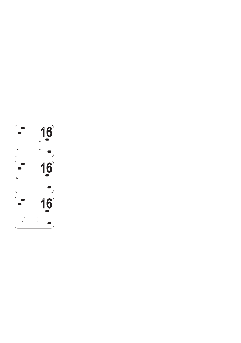
16
Hi
16
16
DSC
DSC
MENU SELECT
BUDDY LIST
LOCAL/DIST
CONTRAST
GPS/DATA
Hi
DSC
GPS/DATA
MANUA L
SETTING
GPS SOURCE
Hi
DSC
RESTRICTED
12:28 LOC
M27 56.020 N
082
50.190 W
GPS setup
If a GPS receiver is connected to the NMEA port of the V90, the radio
will automatically receive the vessel’s position and local time from
the GPS.
If GPS data is not available for some reason, the radio will sound the
NO GPS alert for 2 minutes (or until you press any key).
If the GPS data becomes older than 4 hours, the NO GPS alert will
sound, and it can only be silenced manually or by the reception or
manual entry of new GPS data.
If the vessel’s GPS data is older than 23.5 hours, the data will be
erased and the NO GPS alert will sound.
Manually entering position and UTC time
¼ Note: This function is only shown when there is no GPS receiver
PRI
USA
PRI
USA
PRI
A
USA
connected.
1. Select MENU → GPS/ DATA → MANUAL.
2. Enter the latitude, then the longitude, then the UTC.
When you have finished, the latitude, longitude and UTC time will
be shown on the standby screen. The prefix M indicates a manual
entry.
¼ Notes:
• Manual entries are cancelled if a real GPS position is received.
• A warning will be displayed after 4 hours to remind you that the
current position information was manually entered.
94 |
Setup | V90 Operating Manual
Page 95
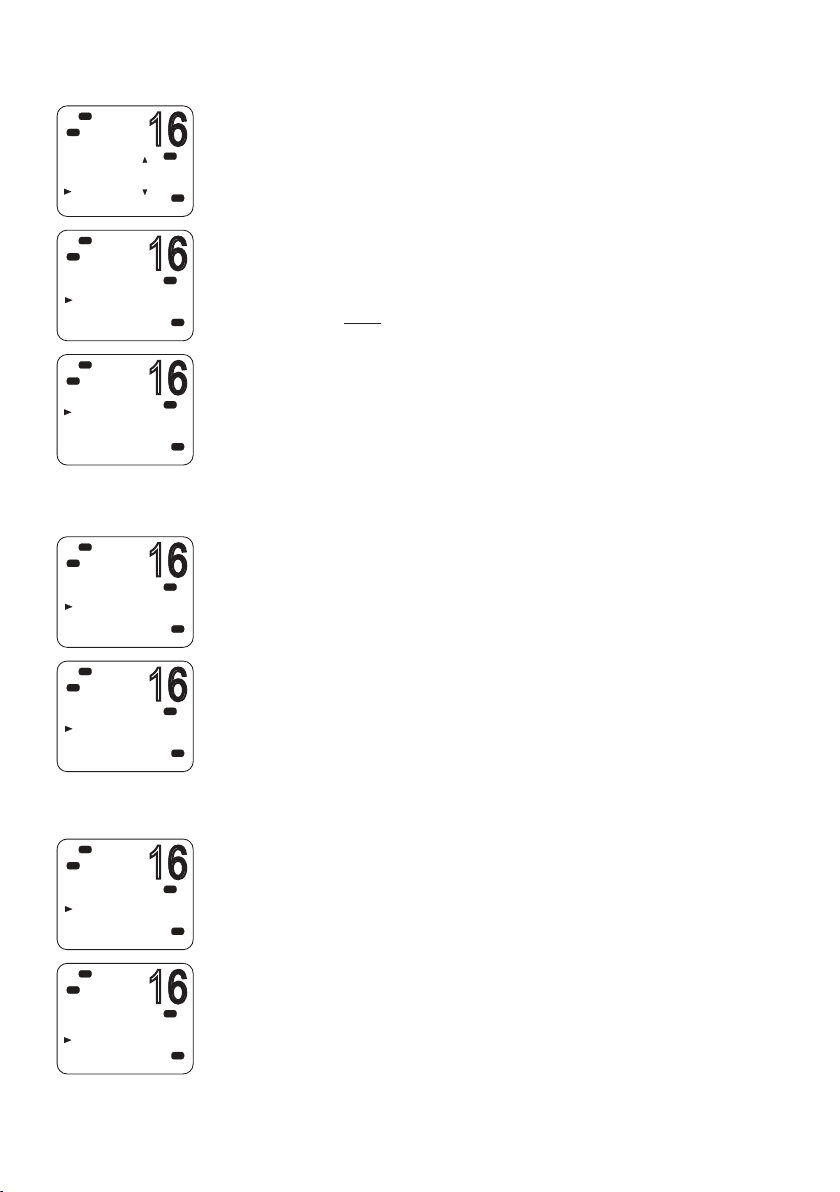
Setting up local time oset
16
16
16
16
16
16
16
Hi
DSC
DSC
MENU SELECT
BUDDY LIST
LOCAL/DIST
CONTRAST
GPS/DATA
Hi
DSC
GPS/DATA
MANUA L
SETTING
GPS SOURCE
Hi
DSC
SETTING
TIME OFF SET
TIME FORMAT
TIME DISPLY
LL DISPLY
Hi
DSC
GPS/DATA
MANUA L
SETTING
GPS SOURCE
Hi
DSC
SETTING
TIME OFF SET
TIME FORMAT
TIME DISPLY
LL DISPLY
If your position and time data are being updated through a GPS
PRI
USA
receiver, you can enter the time difference between UTC and local
time. Then the local time will be displayed on the screen.
1. Select MENU → GPS/ DATA → SETTING → TIME OFFSET
2. Enter the difference between UTC and local time.
You can set in quarter-hour increments up to a maximum offset of
PRI
USA
±13 hours.
¼ Note: When local time is being displayed, LOC is displayed after the
time on the standby screen.
PRI
USA
Time format options
Time can be shown in 12 or 24 hour format.
1. Select MENU → GPS/ DATA → SETTING → TIME FORMAT.
PRI
2. Select 12- or 24-hour as required.
USA
¼ Note: When the 12-hour format has been selected, the time is
displayed with an AM or PM suffix.
PRI
USA
Hi
DSC
GPS/DATA
MANUA L
SETTING
GPS SOURCE
Hi
DSC
SETTING
TIME OFF SET
TIME FORMAT
TIME DISPLY
LL DISPLY
Time display options
You can toggle on or off the time display on the handset screens.
PRI
1. Select MENU → GPS/ DATA → SETTING → TIME DISPLY.
2. Select ON or OFF as required.
USA
PRI
USA
Setup | V90 Operating Manual
| 95
Page 96

16
Hi
16
16
16
16
16
DSC
GPS/DATA
MANUA L
SETTING
GPS SOURCE
Lo
Hi
DSC
SETTING
TIME OFF SET
TIME FORMAT
TIME DISPLY
LL DISPLY
Position display options
You can display or hide your vessel’s position on screen.
PRI
1. Select MENU → GPS/ DATA → SETTING → LL DISPLY.
USA
2. Select ON or OFF as required.
PRI
USA
Course and speed display options
Hi
DSC
GPS/DATA
MANUA L
SETTING
GPS SOURCE
Lo
Hi
DSC
SETTING
TIME FORMAT
TIME DISPLY
LL DISPLY
COG/SOG
Hi
DSC
GPS/DATA
MANUA L
SETTING
GPS SOURCE
Lo
Hi
DSC
SETTING
TIME DISPLY
LL DISPLY
COG/SOG
GPS ALERT
If position and time are being updated through a GPS navigation
receiver, you can display or hide your course over ground (COG) and
PRI
USA
speed over ground (SOG) data on screen.
1. Select MENU → GPS/ DATA → SETTING → COG/SOG.
2. Select ON or OFF as required.
PRI
USA
GPS alert options
If the GPS Alert setting is ON and no GPS signal is received for a
period of 10 minutes, the alarm will sound for 2 minutes.
1. Select MENU → GPS/ DATA → SETTING → GPS ALERT.
PRI
2. Select ON or OFF as required.
USA
¼ Note: The default setting is ON for the V90 EU and OFF for the V90
US.
PRI
USA
96 |
Setup | V90 Operating Manual
Page 97

General setup
16
16
16
16
Radio sensitivity
Lo
Hi
DSC
DSC
MENU SELECT
N2K D ATA
BACKLIGHT
BUDDY LIST
LOCAL/DIST
Hi
DSC
SENSITIVITY
DISTANT
LOCA L
Hi
DSC
MENU SELECT
RADIO SETU
DSC SETUP
AIS SETUP
GPS SIM
Hi
DSC
GPS SIM
ON
OFF
LOCAL/DIST allows you to set the sensitivity of the radio as follows:
PRI
A
USA
• LOCAL
Recommended for use in areas of high radio noise; for example,
close to cities. It is not recommended for open sea conditions.
Local is displayed on the handset screen.
• DIS TAN T
PRI
USA
Recommended for open sea conditions.
1. Select MENU → LOCAL/DIST.
2. Scroll to DISTANT or LOCAL as required.
3. Press [OK].
¼ Note: See also “Adjusting squelch” on page 26.
Display contrast level
Select MENU → CONTRAST.
1. Use the ▲ or ▼ keys to raise or lower the contrast.
2. Press [OK] to accept the setting.
GPS simulator
The GPS simulator creates GPS data for test purposes.
1. Select MENU → GPS SIM.
PRI
2. Select ON or OFF as required.
¼ Notes:
• The GPS simulator is set to OFF whenever the radio is turned on or
PRI
USA
whenever real GPS data is available through the COM port.
• The radio will be blocked from sending DSC calls while the GPS
simulator is on.
Setup | V90 Operating Manual
| 97
Page 98

16
Hi
16
16
16
16
DSC
MENU SELECT
AIS SETUP
GPS SIM
HS SETTING
RESET
Hi
DSC
RESET RADIO
ARE YOU SURE
YES
NO
Hi
DSC
C
MENU SELECT
WAYPOINT
N2K D ATA
BACKLIGHT
BUDDY LIST
Hi
DSC
C
BACKLIGHT
LEVEL
N2K GROUP
Hi
DSC
C
BACKLIGHT
LO H I
PRESS O K
Reset to factory defaults
PRI
USA
PRI
USA
This option returns every setting in the V90 to factory default values.
However, MMSI settings and entries in your buddy list are preserved.
1. Select MENU → RE SET.
2. Select YES to confirm and reset the radio, or NO to exit without
resetting.
Backlight level
This option sets the brightness of the LCD screen and keypad.
1. Select MENU → BACKLIGHT → LEVEL.
2. Use the ▲ and ▼ keys to set the level required.
USA
3. Press [OK] to enable the setting and return to the menu.
¼ Notes:
• The DISTRESS key backlight cannot be turned down.
USA
• If the backlight setting is set to level 0 (off), the backlight will
automatically turn ON at level 1 if the radio detects any DSC activity,
or any buttons are pressed. The backlight will return to level 0 (off)
after 10 seconds of inactivity.
USA
98 |
Setup | V90 Operating Manual
Page 99

9
Appendices
Appendix 1 - Troubleshooting
1. The radio will not power up.
A fuse may have blown or there is no voltage getting to the
transceiver.
Check the power cable for cuts, breaks, or squashed sections.
After checking the wiring, replace the 10 Amp fuse.
Check the battery voltage. This must be at least 10.5V.
2. The transceiver blows the fuse when the power is switched on.
The power wires may have been reversed.
Check that the red wire is connected to the positive battery
terminal, and the black wire is connected to the negative battery
terminal.
3. The speaker makes popping or whining noises when the vessel’s
engine is running.
Electrical noise may be interfering with the transceiver.
Re-route the power cables away from the engine.
Add a noise suppressor to the power cable.
Use resistive spark plug wires and/or use an alternator whine filter.
4. No sound from the external speaker.
Check that the external speaker is enabled in Setup. See “External
speaker” on page 79.
Check that the external speaker cable is physically connected.
Check the soldering of the external speaker cable.
5. Transmissions are always on low power, even when high (Hi) power
is selected.
The antenna may be faulty.
Test the transceiver with a different antenna.
Have the antenna checked out.
Appendices | V90 Operating Manual
| 99
Page 100

6. Battery symbol is displayed.
The power supply is too low.
Check the battery voltage. This should be at least 10.5 V ± 0.5 V DC.
Check the alternator on the vessel.
7. GPS alarm sounds and LCD shows: Please check GPS link! The NO
GPS symbol is shown.
GPS data has been lost. This sequence will repeat every 4 hours
until GPS data from an operational GPS receiver is available. The GPS
cable may faulty or the GPS setting may be incorrect:
Check that the GPS cable is physically connected.
Check the polarity of the GPS cable.
Check the baud rate setting of the GPS if applicable. The baud rate
setting should be 4800. Parity should be set to NONE.
Appendix 2 - Keys reference
VOL
The volume control is on the side of V90 handset
This key also adjusts the volume of an external speaker, if connected.
16 / 9
100 |
Press [16/9] to immediately switch to the priority channel.
Press again to return to your original channel. The default Priority
Channel is CH16.
In the USA, you can toggle between Channel 16 and Channel 9 as
the priority channel. Hold down [16/9] until a beep sounds and the
required priority channel is displayed.
DISTRESS
The red [DISTRESS] key on top of the handset sends a DSC distress
call.
DSC must be switched on and an MMSI must have been entered
into the radio.
For more information about distress calls, see “Introduction to DSC”
on page 45.
Appendices | V90 Operating Manual
 Loading...