


Pascal Villeneuve, VA2PV, va2pv@arrl.org
Product Review
Icom IC-V3500 FM VHF Transceiver
Reviewed by Rick Palm, K1CE
k1ce@arrl.net
The Icom IC-V3500 is a basic but multi-featured, highpower, compact (1.6 × 5.5 × 4.6 inches), simple-to-operate FM VHF transceiver that has
a large heatsink on the bottom and back
panel that helps ensure stable output during high-power transmissions (see Table 1
and Figure 1). Power settings are switchable: 65, 25, 10, and 5 W. While the
IC-V3500 transmits from 144 – 148 MHz,
the receiver covers 136 – 174 MHz,
home to a variety of other radio services
— such as aeronautical, satellite, and space
services, as well as the marine channels.
The radio features 207 alphanumeric memory channels, which include 200 regular channels, one call
channel, and three pairs of scan edge memories
(1 A/B, 2 A/B, and 3 A/B).
The Icom IC-V3500 radio is built and tested to US military speci cations, MIL-STD 810G. For more information about the method and procedure, you can download the product brochure at www.icomamerica.com/
en/downloads/DownloadDocument.aspx?Docu
ment=1132.
Out of the box, the front panel features a white, easyto-read, uncluttered LCD screen, with large characters.
Radio function labels along the bottom of the screen
create identi ers for the front panel function pushbuttons in low light and during nighttime operation.
AF output is about 4.5 W to a top- ring loudspeaker.
The manufacturer’s literature states that both the frequency response and opening slits have been
improved from similar models. It also states that setup
presets exist to raise, lower, or mute the radio for those
who like precise audio levels.
A safety alert is an emergency call function to send
beeps and hot microphone audio to others. While the
emergency call function is active, the speaker will
amplify messages to notify others within range.
Other features include built-in CTCSS and DTCS
encoders/decoders for repeaters and simplex access;
a bank link scan function to scan all memory channels
in a series of selected banks; up to 16 DTMF autodial
memory channels; a priority watch function; wide/
narrow channel settings, and a power supply voltage
display.
Most critical functions can be conveniently changed
with the keypad on the handheld microphone.
Basic Operation
The primary function buttons for programming the
various features of the radio are found along the bottom of the radio’s front panel, with corresponding
labels just above, on the display screen. There are six
rectangular buttons and labels, plus a small round
button at the seven o’clock position under the large
round dial knob. The small round button is for
OPT
, which is pushed to select a speci c bank of memory channels and other functions, such as the emergency alert system (more on this function later). The
BANK
Bottom Line
The Icom IC-V3500 is a basic but multi-featured, high-power (65 W), compact, simple-tooperate FM VHF transceiver. It’s built to support
high-power transmission, and with its highoutput speaker, it’s an ideal radio for public
event and emergency communications.
38 April 2023 QST www.arrl.org
Reprinted with permission; copyright ARRL.
six main buttons are positioned
left to right — the rst is the
LOCK
button, which is pushed to
enter the
SET
mode, with various
SET
selectable operating parameters
such as the repeater tone frequency (most repeaters seem to
use the easy-to-remember subaudible 123 Hz tone frequency to
open the repeater to the user’s
Table 1
Icom IC-V3500, serial number 65001140, FCC ID# AFJ325110
Manufacturer’s Specifi cations Measured in the ARRL Lab
Frequency coverage: Receive, 136 – As speci ed.
174 MHz; transmit, 144 – 148.
Modes: FM, FM-Narrow (FM-N). As speci ed.
Power requirements: Transmit, 11 A at 65 W At 13.8 V dc: Receive, no signal, maximum;
RF output; receive, 0.4 – 1.5 A at 13.8 V dc; audio and backlights, 670 mA; lights at
power supply, 13.8 V dc ± 15%. mininum, 650 mA. Power off, 0 mA
transmission).
There are 19 selectable parameters on the
SET
mode list,
including ones for tone squelch
operation and frequency offset
(which sometimes can be a nonstandard offset between the
transmit and receive frequencies,
such as 1 MHz; usual offset is
600 kHz). Other adjustable
parameters include the memory
channel skip function, which is
Receiver Receiver Dynamic Testing*
Sensitivity: FM 12 dB SINAD: 136 – –125 dBm / 0.13 μV.
174 MHz, 0.18 μV.
FM two-tone, third-order IMD dynamic 20 kHz offset: 72 dB;
range: Not speci ed. 10 MHz offset: 83 dB.
FM two-tone, second-order IMD dynamic 84 dB.
range: Not speci ed.
Adjacent-channel rejection: Not speci ed. 20 kHz offset: 72 dB.
Squelch sensitivity:
S-meter sensitivity: Not speci ed. S-9: 2.8 μV.
Audio output power: At least 3.5 W, 4.4 W at 10% THD; THD at 1 V
4.5 W typical into 4 at 10% THD.
helpful during a memory scan to
eliminate a usually busy, but not
desired channel, for efficient
monitoring. A transmit permission
parameter inhibits transmission
(for example, an operator with
young children who may accidentally gain access to the radio
cannot transmit). The weather
alert parameter can be switched
off or on.
There is an initial
SET
mode,
which contains the 15 “set and
Transmitter Transmitter Dynamic Testing
Power output: High/medium/low power, As speci ed.
65/25/10/5 W.
Spurious-signal and harmonic suppression: >68 dB. Meets FCC requirements.
60 dB.
Transmit-receive turnaround time (PTT Squelch on, S-9 signal: 95 ms.
release to 50% of full audio output):
Not speci ed.
Receive-transmit turnaround time (TX delay): 59 ms.
Not speci ed.
Size (height, width, depth): 1.6 × 5.5 × 4.6 inches.
Weight: 2.4 pounds (radio body, control head, and control cable).
*Test results shown are for standard FM mode. Sensitivity, adjacent channel rejection,
and dynamic range increased by 1 dB in FM narrow mode.
†
Measurement was noise limited at the value indicated.
forget” parameters that generally
do not get changed as often as
the regular
play initial
SET
mode functions. I like the voltage dis-
SET
function to be on, which allows me a
quick, initial check of my battery’s voltage. The
OPT
parameter assigns one of three functions to the
BANK OPT
key, which is usually set to allow selection
of the various programmed memory banks.
BANK
transmit (high/mid/mid low/low):
9.8/5.9/3.8/2.8 A.
†
†
Not speci ed. At threshold: 0.08 μV;
at maximum: 4.1 μV.
channels, marine channels, etc. Push the
button several times to select the frequency step from
10 MHz to 1 MHz.
, 0.9%.
RMS
V/MHZ SCAN
The IC-V3500 features two basic modes of operation:
the VFO mode and the memory mode. Brie y push
the
V/MHZ SCAN
button to select the VFO mode, and
turn the dial knob to select a frequency. The frequency
changes according to the selected tuning step. The
144 – 148 MHz 2-meter band allows for transmission/
reception, as it is the amateur band; extended range,
where transmission is inhibited, is 136 – 174 MHz,
which covers, among other services, some aviation
Reprinted with permission; copyright ARRL.
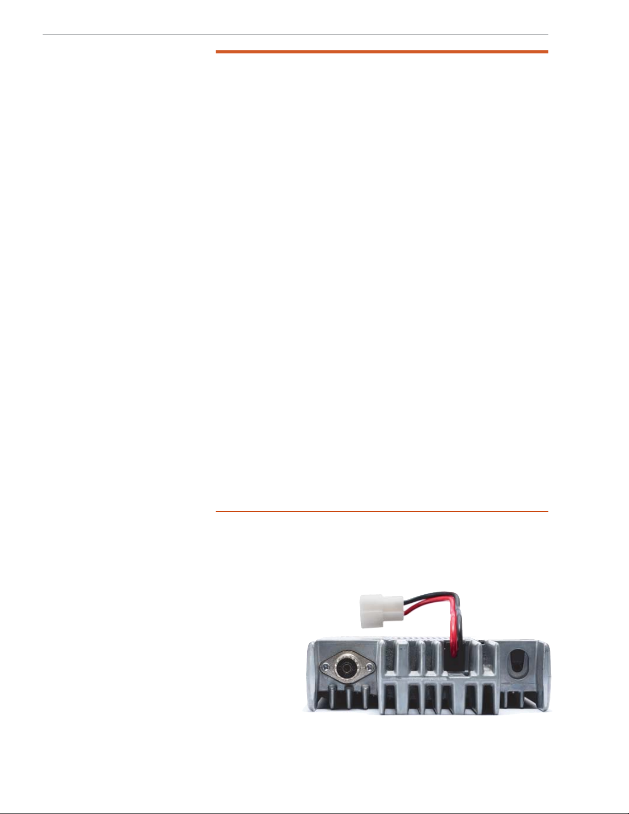
Figure 1 — The Icom IC-V3500 rear panel.
www.arrl.org QST April 2023 39
 Loading...