

Page 1
INSTRUCTION MANUAL
VHF MARINE TRANSCEIVERS
|M220
|M220G
Page 2

Thank you for choosing this Icom product.
This product is designed and built with Icom’ s state of the art technology and
craftsmanship. With proper care, this product should provide you with years of troublefree operation.
■ IMPORTANT
READ ALL INSTRUCTIONS carefully and
completely before using the transceiver.
SAVE THIS INSTRUCTION MANUAL —
This instruction manual contains important
operating instructions for the IC-M220,
IC-M220G.
This instruction manual includes some
functions that are usable only when they
are preset by your dealer.
Ask your dealer for details.
■ EXPLICIT DEFINITIONS
WORD
RWARNING!
CAUTION
NOTE
DEFINITION
Personal injury, re hazard
or electric shock may
occur.
Equipment damage may
occur.
If disregarded,
inconvenience only. No risk
of personal injury, re or
electric shock.
■ FEATURES
z Flexible installation with a compact body
z Easy user interface
The transceiver is equipped with a
screen for easy readability and easy-touse user interface.
z Dualwatch and Tri-watch functions
Convenient functions that enable you
to monitor the Distress channel (Ch
16) while receiving on another channel
(Dualwatch), or while receiving on
another channel, and the Call channel
(Tri-watch).
z Built-in Class D DSC function
The transceiver has the DSC functions
for distress alert transmission and
reception, as well as the general DSC
calls such as Individual calls, All ships
calls, Group calls, and so on.
z Built-in GPS receiver
IC-M220G)
(For only the
Icom is not responsible for the
destruction, damage to, or performance
of any Icom or non-Icom equipment, if the
malfunction is because of:
• Force majeure, including, but not
limited to, res, earthquakes, storms,
oods, lightning, other natural disasters,
disturbances, riots, war, or radioactive
contamination.
• The use of Icom transceivers with any
equipment that is not manufactured or
approved by Icom.
ii
Icom, Icom Inc. and the Icom logo are
registered trademarks of Icom Incorporated
(Japan) in Japan, the United States, the
United Kingdom, Germany, France, Spain,
Russia, Australia, New Zealand, and/or
other countries.
AquaQuake is a trademark of Icom
Incorporated.
All other products or brands are registered
trademarks or trademarks of their
respective holders.
Page 3
■ IN CASE OF EMERGENCY
If your vessel requires assistance, contact other vessels and the Coast Guard by sending
a distress call on Channel 16, or, transmit your Distress call using Digital Selective Calling
(DSC) on Channel 70.
D USING CHANNEL 16
1. Push [16/C] to switch to Channel 16.
2. While holding down [PTT], give the appropriate information as follows:
1
2
3
4
z “MAYDAY MAYDAY MAYDAY.”
z “THIS IS ” (name of vessel).
z Say your call sign or other indication of the vessel
(AND your 9 digit DSC ID, if you have one).
z “LOCATED AT ” (your position).
z State the nature of the distress and assistance required.
z Give any other information which might facilitate the rescue.
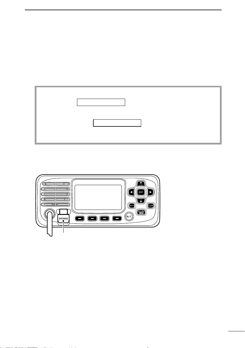
D USING DIGITAL SELECTIVE CALLING
1. Lift up the key cover, hold down [DISTRESS] for 3 seconds until the 3 short beeps
and then one long beep sound.
Key cover
2. Wait for an acknowledgment from another station.
3. After the acknowledgement is received, Channel 16 is automatically selected.
4. Hold down [PTT], then transmit the appropriate information as listed above.
5
6
7
8
9
10
11
12
13
14
15
16
17
18
iii
Page 4

■ RADIO OPERATION WARNING
Icom requires the radio operator to meet the FCC Requirements for Radio
Frequency Exposure. An omnidirectional antenna with gain not greater than
9 dBi must be mounted a minimum of 5 meters (measured from the lowest
WARNING
on the FCC Safe Maximum Permissible Exposure (MPE) distance of 3 meters added to
the height of an adult (2 meters) and is appropriate for all vessels.
For watercraft without suitable structures, the antenna must be mounted so as to maintain
a minimum of 1 meter vertically between the antenna, (measured from the lowest point
of the antenna), to the heads of all persons AND all persons must stay outside of the 3
meter MPE radius.
Do not transmit with radio and antenna when persons are within the MPE radius of
the antenna, unless such persons (such as driver or radio operator) are shielded from
antenna eld by a grounded metallic barrier. The MPE Radius is the minimum distance
from the antenna axis that person should maintain in order to avoid RF exposure higher
than the allowable MPE level set by FCC.
FAILURE TO OBSERVE THESE LIMITS MAY ALLOW THOSE WITHIN THE MPE
RADIUS TO EXPERIENCE RF RADIATION ABSORPTION WHICH EXCEEDS THE
FCC MAXIMUM PERMISSIBLE EXPOSURE (MPE) LIMIT.
IT IS THE RESPONSIBILITY OF THE RADIO OPERATOR TO ENSURE THAT THE
MAXIMUM PERMISSIBLE EXPOSURE LIMITS ARE OBSERVED AT ALL TIMES
DURING RADIO TRANSMISSION. THE RADIO OPERATOR IS TO ENSURE THAT
NO BYSTANDERS COME WITHIN THE RADIUS OF THE MAXIMUM PERMISSIBLE
EXPOSURE LIMITS.
point of the antenna) vertically above the main deck and all possible
personnel. This is the minimum safe separation distance estimated to meet
all RF exposure compliance requirements. This 5 meter distance is based
Determining MPE Radius
THE MAXIMUM PERMISSIBLE EXPOSURE (MPE) RADIUS HAS BEEN ESTIMATED
TO BE A RADIUS OF ABOUT 3M PER OET BULLETIN 65 OF THE FCC.
THIS ESTIMATE IS MADE ASSUMING THE MAXIMUM POWER OF THE RADIO AND
ANTENNAS WITH A MAXIMUM GAIN OF 9dBi ARE USED FOR A SHIP MOUNTED
SYSTEM.
iv
Page 5

AVERTISSEMENT
■ AVERTISSEMENT POUR LES OPÉRATEURS RADIO
Icom exige que l’opérateur radio se conforme aux exigences de la FCC
en matière d’exposition aux radiofréquences. Une antenne
omnidirectionnelle dont le gain ne dépasse pas 9dBi doit être xée à
une distance minimale de 5 mètres (mesurée depuis le point le plus bas
de l’antenne) verticalement au-dessus du pont principal et de tout le
personnel qui peut s’y trouver. Il s’agit de la distance de sécurité
minimale prévue pour satisfaire aux exigences de conformité en matière d’exposition aux
RF. Cette distance de 5 mètres est établie en fonction de l’exposition maximale
admissible sécuritaire de 3 mètres établie par la FCC, à laquelle on ajoute la hauteur d’un
adulte (2 mètres); cette distance convient pour tous les navires.
1
2
3
4
5
Dans le cas des embarcations sans structure convenable, l’antenne doit être xée de
façon à maintenir une distance minimale de 1 mètre verticalement entre cette antenne
(mesurée depuis son point le plus bas) et la tête de toute personne présente; toutes
les personnes présentes doivent se tenir à l’extérieur d’un rayon d’exposition maximale
admissible de 3 mètres.
Ne pas émettre à l’aide de la radio et de l’antenne lorsque des personnes se trouvent à
l’intérieur du rayon d’exposition maximale admissible de cette antenne, à moins que ces
personnes (comme le conducteur ou l’opérateur radio) ne soient protégées du champ
de l’antenne par un écran métallique relié à la masse. Le rayon d’exposition maximale
admissible équivaut à la distance minimale que cette personne doit maintenir entre elle
et l’axe de l’antenne pour éviter une exposition aux RF supérieure au niveau d’exposition
maximale admissible xé par la FCC.
LE NON-RESPECT DE CES LIMITES PEUT CAUSER, POUR LES PERSONNES
SITUÉES DANS LE RAYON D’EXPOSITION MAXIMALE ADMISSIBLE, UNE
ABSORPTION DE RAYONNEMENT DE RF SUPÉRIEURE À L’EXPOSITION
MAXIMALE ADMISSIBLE FIXÉE PAR LA FCC.
L’OPÉRATEUR RADIO EST RESPONSABLE D’ASSURER QUE LES LIMITES
D’EXPOSITION MAXIMALE ADMISSIBLE SOIENT RESPECTÉES EN TOUT TEMPS
PENDANT LA TRANSMISSION RADIO. L’OPÉRATEUR RADIO DOIT S’ASSURER
QU’AUCUNE PERSONNE PRÉSENTE NE SE SITUE À L’INTÉRIEUR DU RAYON
D’EXPOSITION MAXIMALE ADMISSIBLE.
Établir le rayon d’exposition maximale admissible
ON ESTIME QUE LE RAYON D’EXPOSITION MAXIMALE ADMISSIBLE EST
D’ENVIRON 3 M, TEL QUE STIPULÉ DANS LE BULLETIN OET 65 DE LA FCC.
CETTE DISTANCE ESTIMÉE TIENT COMPTE D’UN SYSTÈME INSTALLÉ SUR UN
NAVIRE UTILISANT LA PUISSANCE MAXIMALE DE LA RADIO ET DES ANTENNES
DONT LE GAIN MAXIMAL EST DE 9dBi.
Determining MPE Radius
THE MAXIMUM PERMISSIBLE EXPOSURE (MPE) RADIUS HAS BEEN ESTIMATED
TO BE A RADIUS OF ABOUT 3M PER OET BULLETIN 65 OF THE FCC.
THIS ESTIMATE IS MADE ASSUMING THE MAXIMUM POWER OF THE RADIO AND
ANTENNAS WITH A MAXIMUM GAIN OF 9dBi ARE USED FOR A SHIP MOUNTED
SYSTEM.
6
7
8
9
10
11
12
13
14
15
16
17
18
v
Page 6
■ FCC INFORMATION
This equipment has been tested and found to comply with the limits for a Class A digital
device, pursuant to part 15 of the FCC Rules. These limits are designed to provide
reasonable protection against harmful interference when the equipment is operated
in a commercial environment. This equipment generates, uses, and can radiate radio
frequency energy and, if not installed and used in accordance with the instruction manual,
may cause harmful interference to radio communications.
Operation of this equipment in a residential area is likely to cause harmful interference in
which case the user will be required to correct the interference at his own expense.
CAUTION: Changes or modications to this transceiver, not expressly approved by
Icom Inc., could void your authority to operate this transceiver under FCC regulations.
■ INFORMATION FCC
Cet équipement a été testé et reconnu conforme aux limites xées pour un appareil
numérique de classe A, conformément au point 15 de la réglementation FCC. Ces limites
sont dénies de façon à fournir une protection raisonnable contre le brouillage préjudiciable
lorsque cet appareil est utilisé dans un environnement commercial. Cet équipement
génère, utilise et peut émettre un rayonnement de fréquence radio. S’il n’a pas été installé
conformément aux instructions, il peut par ailleurs créer des interférences perturbant les
communications radio.
L’utilisation de cet appareil dans une zone résidentielle peut provoquer un brouillage
préjudiciable, auquel cas l’utilisateur sera tenu de corriger la situation à ses frais.
MISE EN GARDE: Tout changement ou modication, non expressément approuvé par
Icom Inc., peut annuler l’autorisation de l’utilisateur à utiliser cet appareil conformément
à la réglementation FCC.
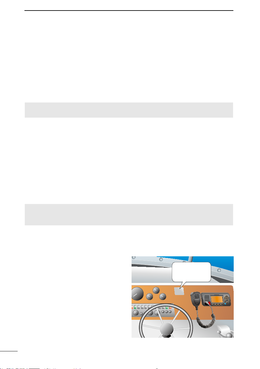
■ NOTE
A WARNING STICKER is supplied with
the USA version transceiver.
To comply with FCC regulations, this sticker
must be afxed in such a location as to be
readily seen from the operating controls of
the radio as in the diagram below. Make
sure the chosen location is clean and dry
before applying the sticker.
vi
WARNING
STICKER
WARNING.
Page 7

■ PRECAUTIONS
R WARNING! NEVER connect the
transceiver directly to an AC outlet. This
may cause a re or an electric shock.
R WARNING! NEVER connect the
transceiver to a power source of more
than 16 V DC such as a 24 V battery. This
connection could cause a re or damage
the transceiver.
R WARNING! NEVER reverse the DC
power cable polarity. This could cause a
re or damage the equipment.
R WARNING! NEVER cut the DC power
cable between the DC power connector
on the transceiver’s rear panel and the
fuse holder. If an incorrect connection is
made after cutting, the transceiver may be
damaged.
R WARNING! NEVER operate the
transceiver during a lightning storm. It may
result in an electric shock, cause a re or
damage the transceiver. Always disconnect
the power source and antenna before a
storm.
R WARNING! NEVER place the
transceiver where normal operation of the
vessel may be hindered, or where it could
cause bodily injury.
CAUTION: DO NOT place or leave the
transceiver in areas with temperatures
below –20°C ~ +60°C (–4ºF ~ +140ºF), or
in areas subject to direct sunlight, such as
a dashboard.
CAUTION: DO NOT use harsh solvents
such as Benzine or alcohol when cleaning.
This could damage the equipment
surfaces. If the surface becomes dusty or
dirty, wipe it clean with a soft, dry cloth.
BE CAREFUL! The transceiver’s rear
panel will become hot when transmitting
continuously for long periods of time.
BE CAREFUL! The transceiver meets
IPX7 requirements for waterproof
protection*. However, once the transceiver
or microphone has been dropped,
or the waterproof seal is cracked or
damaged, waterproof protection cannot be
guaranteed because of possible damage to
the case or the waterproof seal.
* Except for the DC power connector,
NMEA In/Out leads and AF Out leads.
NOTE: Install the transceiver and/or
microphone more than 1 meter from the
vessel’s magnetic navigation compass.
NOTE: Place the transceiver in a secure
place to avoid inadvertent use by
unauthorized persons.
1
2
3
4
5
6
7
8
9
10
11
12
13
14
15
16
17
18
vii
Page 8

■ PRÉCAUTIONS
R AVERTISSEMENT ! NE JAMAIS relier
l’émetteur-récepteur à une prise CA. Cela
pourrait provoquer un choc électrique ou un
incendie.
R AVERTISSEMENT ! NE JAMAIS
brancher l’émetteur-récepteur sur une
source d’alimentation supérieure à 16 V
CC, comme une batterie de 24 V. Cela
pourrait endommager l’émetteur-récepteur.
R AVERTISSEMENT ! NE JAMAIS
inverser la polarité du câble d’alimentation
CC lors de la connexion à une source
d’alimentation. Cela pourrait endommager
l’émetteur-récepteur.
R AVERTISSEMENT ! NE JAMAIS
couper le câble d’alimentation CC entre la
prise CC a l’arrière de l’émetteur-récepteur
et le porte-fusible. L’émetteur-récepteur
peut être endommagé par la suite en cas
de connexion inappropriée.
R AVERTISSEMENT ! NE JAMAIS utiliser
l’émetteur-récepteur durant un orage. Cela
risquerait de provoquer un choc électrique,
un incendie ou d’endommager l’émetteurrécepteur. Toujours débrancher la source
d’alimentation et l’antenne avant une
tempête.
R AVERTISSEMENT ! NE JAMAIS
installer l’émetteur-récepteur à un
emplacement où il pourrait gêner le
fonctionnement normal du navire ou
provoquer des blessures corporelles.
R MISE EN GARDE : NE PAS utiliser ou
placer l’émetteur-récepteur dans des zones
où la temperature est inférieure à –20°
ou supérieure à +60° ou dans des zones
soumises au rayonnement solaire direct,
telles le tableau de bord.
MISE EN GARDE : NE PAS utiliser
de dissolvants agressifs tels que du
Benzène ou de l’alcool lors du nettoyage,
car ils endommageraient les surfaces
de l’émetteur-récepteur. Si l’émetteurrécepteur est poussiéreux ou sale,
nettoyez-le avec un tissu doux et sec.
MISE EN GARDE : La face arrière de la
VHF chauffe en cas d’utilisation continue
sur une longue durée.
MISE EN GARDE : L’émetteur-récepteur
est étanche conformément à la norme
IPX7*. L’étanchéité ne peut plus être
garantie après une chute de l’appareil en
raison des risques de ssures du boîtier, de
dégradation du joint d’étanchéité, etc.
* Les connecteurs sur le panneau arrière ne
sont pas étanche IPX7.
REMARQUE: INSTALLER la VHF et le
microphone à au moins 1 m du compas de
route du navire.
REMARQUE: Placer l’émetteur-récepteur
hors de portée des enfants pour éviter
toute utilisation inopinée.
Si la face avant est exposée à de l’eau de
mer, ASSUREZ-VOUS DE LE NETTOYER
ENTIEREMENT AVEC DE L’EAU DOUCE
lorsque la protection étanche sur le
panneau avant fonctionne. Dans le cas
contraire, les touches et le commutateur
risquent de ne plus fonctionner en raison
de la cristallisation du sel.
viii
Page 9
■ RECOMMENDATION
ENT
DISTRESS
ENT
ENT
BACK
EXIT
CLEAN THE TRANSCEIVER AND MICROPHONE THOROUGHLY WITH FRESH
WATER after exposure to saltwater, and dry it before operating. Otherwise, the
transceiver’s keys, switches and controllers may become unusable, due to salt
crystallization.
NOTE: If the transceiver’s waterproof protection appears defective, carefully clean it
with a soft, wet (fresh water) cloth, then, dry it before operating.
The transceiver may lose its waterproof protection if the case or microphone is cracked
or broken, the microphone connector is not screwed in completely, or the transceiver
has been dropped.
Contact your Icom distributor or your dealer for advice.
1
2
3
4
5
6
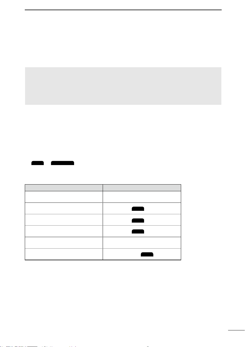
■ KEY ICON DESCRIPTION
The keys are described in this manual as follows:
The keys that have an words or letters on them are described with the characters “[ ]”.
Example: [MENU], [CLR]
The Software Keys are described with the words or letters on a dark background such
as
Push the key below the desired function.
You can use the following keys on the Menu screen.
Select
Enter
Go to the next tree level
Go back to the previous tree level
Cancel
Exit
or
FUNCTION ACTION
. The function of the keys are shown at the bottom of the display.
Push [▼] or [▲].
Push [ENT],
Push [ENT],
Push [CLR],
Push [CLR].
Push [MENU] or
.
, or [►].
, or [◄].
.
7
8
9
10
11
12
13
14
15
16
17
18
ix
Page 10

■ TABLE OF CONTENTS
■ IMPORTANT ......................................ii
■ EXPLICIT DEFINITIONS ...................ii
■ FEATURES ........................................ii
■ IN CASE OF EMERGENCY ..............iii
■ RADIO OPERATION WARNING .......iv
■ AVERTISSEMENT POUR LES
OPÉRATEURS RADIO ..................... v
■ FCC INFORMATION .........................vi
■ INFORMATION FCC .........................vi
■ NOTE ................................................vi
■ PRECAUTIONS ...............................vii
■ PRÉCAUTIONS ..............................viii
■ RECOMMENDATION .......................ix
■ KEY ICON DESCRIPTION ...............ix
1 OPERATING RULES ...........................1
2 PANEL DESCRIPTION ........................2
■ Front panel ........................................ 2
■ Function Display................................3
■ Software Keys ................................... 4
3 PREPARATION .................................... 6
■ Entering the MMSI code....................6
4 BASIC OPERATION ............................7
■ Selecting a channel ........................... 7
■ W
eather channels and Weather Alert
■ Adjusting the volume level ................9
■ Adjusting the squelch level................9
■ A
djusting the backlight or the display
contrast ............................................. 9
■ Setting the Call channel .................. 10
■ Receiving and transmitting .............. 10
■ Aq
uaQuake Water Draining function
■ Editing a channel name................... 11
5 SCAN OPERATION ...........................12
■ Scan types ......................................12
■ Setting Favorite channels................13
■ Starting a scan ................................ 13
6 DUALWATCH/TRI-WATCH ................ 14
■ Description ...................................... 14
■ Operation ........................................14
7 D
IGITAL SELECTIVE CALLING (DSC)
■ DSC address ID .............................. 15
■ Sending DSC calls (other)...............20
■ Receiving DSC calls (Distress) ....... 28
■ Receiving DSC calls (other) ............ 29
■ DSC Log..........................................33
■ Multiple-task mode .......................... 34
■ DSC Settings...................................36
.. 8
.. 11
.. 15
8 MENU SCREEN ................................. 38
■ Using the Menu screen ................... 38
■ Menu items description ................... 40
9 C
ONNECTIONS AND MAINTENANCE
■ Supplied accessories ...................... 43
■ Connecting the microphone ............ 43
■ Connections .................................... 44
■ Connecting to the MA-500TR..........45
■ Fuse replacement ...........................45
■ Cleaning .......................................... 45
■ Mounting the transceiver ................. 46
■ MBF-5 installation ...........................47
10 SPECIFICATIONS AND OPTIONS .... 48
■ Specications .................................. 48
■ Options ............................................ 48
11 TROUBLESHOOTING ....................... 49
12 CHANNEL LIST .................................50
13 TEMPLATE ......................................... 51
INDEX...................................................... 53
.. 43
x
Page 11

OPERATING RULES
D Priorities
• Read all rules and regulations pertaining to priorities and keep an up-to-date copy
handy. Safety and distress calls take priority over all others.
• You must monitor Channel 16 when you are not operating on another channel.
• False or fraudulent distress calls are prohibited under law.
1
1
2
D Privacy
• Information overheard but not intended for you cannot lawfully be used in any way.
• Indecent or profane language is prohibited.
D Radio licenses
(1) SHIP STATION LICENSE
You must have a current radio station license before using the transceiver. It is unlawful to
operate a ship station which is not licensed.
Inquire through your dealer or the appropriate government agency for a ShipRadiotelephone license application. This government-issued license states the call sign
which is your craft’s identication for radio purposes.
(2) OPERATOR’S LICENSE
A Restricted Radiotelephone Operator Permit is the license most often held by small
vessel radio operators when a radio is not required for safety purposes.
The Restricted Radiotelephone Operator Permit must be posted or kept with the operator.
Only a licensed radio operator may operate a transceiver.
However, non-licensed individuals may talk over a transceiver if a licensed operator
starts, supervises, ends the call and makes the necessary log entries.
A current copy of the applicable government rules and regulations is only required to be
on hand for vessels in which a radio telephone is compulsory. However, even if you are
not required to have these on hand it is your responsibility to be thoroughly acquainted
with all pertinent rules and regulations.
3
4
5
6
7
8
9
10
11
12
13
14
15
16
17
18
1
Page 12
2
PANEL DESCRIPTION
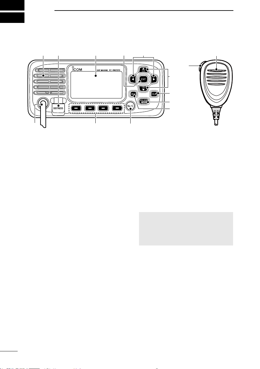
■ Front panel
Function display (p.3)Speaker
1 2 3
1DISTRESS KEY [DISTRESS]
Hold down for 3 seconds to transmit a
Distress call.
2ENTER KEY [ENT]
Push to set the entered data, selected
item, and so on.
3LEFT/RIGHT KEYS [◄]/[►]
• Push to scroll the Software Key
functions. (pp. 4 ~ 5)
• Push to select a character or number
in the entry mode. (pp. 6, 11, 15~16)
4UP/DOWN KEYS [▲]/[▼]
• Push to select an operating channel,
Menu items, Menu settings, and so on.
(pp. 7)
• Push to select a character or number
in the entry mode. (pp. 11, 15~16)
5CLEAR KEY [CLR]
Push to cancel the entered data, or to
return to the previous screen.
6POWER/VOLUME/SQUELCH KEY
[PWR/VOL/SQL]
• Hold down for 1 second to turn the
transceiver ON or OFF.
• Push once to display the volume level
setting screen. (p. 9)
• Push twice to display the squelch level
setting screen. (p. 9)
7MENU KEY [MENU]
Push to display or close the Menu
screen.
Microphone
4
5
6
7
89
8CHANNEL 16/CALL CHANNEL KEY
[16/C]
• Push to select Channel 16. (p. 7)
• Hold down for 1 second to select the
Call channel. (p. 7)
9SOFTWARE KEYS (pp.4 ~ 5)
Scrollthekeyfunctionspushing[◄]or
[►],thenpusheitherofthe4software
keys to select the function displayed at
the bottom of the display.
MICROPHONE CONNECTOR
CAUTION: Be sure that the
microphone connector is tightened
completely (rotate clockwise) to
maintain the transceiver’s waterproof
protection.
PTT SWITCH [PTT] (p. 10)
Hold down to transmit, release to receive.
2
Page 13
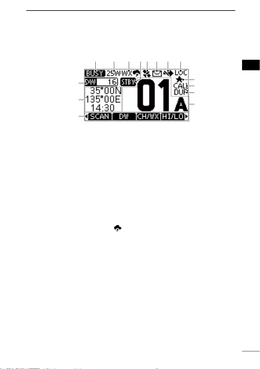
■ Function Display
1 2 3 4 5 6 7 8
PANEL DESCRIPTION
2
1
2
1STATUS INDICATOR (p. 10)
• TX: Displayed while transmitting.
• BUSY: Displayed while receiving, or
the squelch is open.
2POWER INDICATOR (p. 5)
• 25W: High power
• 1W: Low power
3CHANNEL GROUP INDICATOR
(pp.7~8)
Displays the selected channel group, INT
(International), USA, CAN (Canada), WX
(Weather channel).
L The selectable channels differ,
depending on the version or presetting.
L When the WX-Alert is set to ON, “
displayed. (For only the USA version)
4STATUS INDICATOR
• STBY: Standby mode.
• RT: Displayed when the channel
is changed while receiving or
transmitting a signal.
5GPS ICON
• Displayed when valid GPS position
data is received.
• Blinks while no position data is
received.
6MAIL ICON (p. 33)
• Displayed when there is an unread
DSC message.
• Blinks until one of the called messages
is read.
9
7CHANNEL SWITCH ICON (p. 36)
Displayed when the “CH Auto SW” is set to
“Ignore after 10 sec.” or “Manual.”
8LOCAL INDICATOR
Displayed when the RF Attenuation is ON.
(For only the USA version)
9FAVORITE CHANNEL (p. 13)
Displayed when a Favorite channel is
selected.
CALL CHANNEL (p. 10)
Displayed when a Call channel is selected.
DUPLEX CHANNEL
Displayed when a Duplex channel is
” is
selected.
OPERATING CHANNEL NUMBER
(pp. 7, 11)
Displays the selected operating channel
number.
L “A” or “B” is displayed when a simplex
channel is selected.
SOFTWARE KEYS FUNCTION
DISPLAY (p. 4 ~ 5)
The functions of each keys are
displayed. See “Software keys” on the
next page for details.
3
4
5
6
7
8
9
10
11
12
13
14
15
16
17
18
(☞Continued on the next page)
3
Page 14
2
PANEL DESCRIPTION
■ Function Display (Continued)
POSITION/TIME READOUTS
Readouts the current position and time
when valid GPS data is received, or
when manually entered.
Received GPS data:
• “NO POS NO TIME” is displayed if
no GPS data has been received, and
then a warning message is displayed
for 2 minutes after turning ON the
transceiver.
• “??” blinks if no GPS data is received
for 30 seconds after receiving valid
GPS data, and then “??” and a
warning message are displayed after
10 minutes.
• A warning message is displayed if no
GPS data is received for 4 hours after
receiving valid GPS data.
Manually entered GPS data:
• A manually entered GPS data is valid
for 23.5 hours, and then a warning
message is displayed.
SCAN INDICATOR
• “SCAN” or “SCAN 16” is displayed while
scanning. (p. 13)
• “DW” or “TW” and the watched channel
number is displayed while using the
Dualwatch or Tri-watch function. (p. 14)
(p. 16)
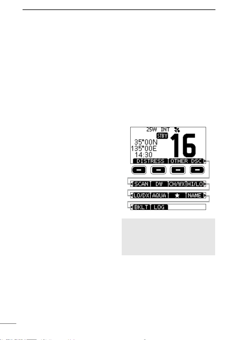
■ Software Keys
Various often-used functions are assigned
to the Software Keys for easy access. The
functions’ icons are displayed above the
Software Keys, as shown below.
D Selecting a Software Key
function
Push[◄]or[►]toslidethroughthe
selectable functions that are assigned to
the Software Keys.
Push the Software Key under the function’s
icon to select the function.
NOTE: The displayed icons or their order
may differ, depending on the transceiver
version or the presetting.
When the MMSI code is not set, the
Software Keys for the DSC function are
not displayed.
4
Page 15
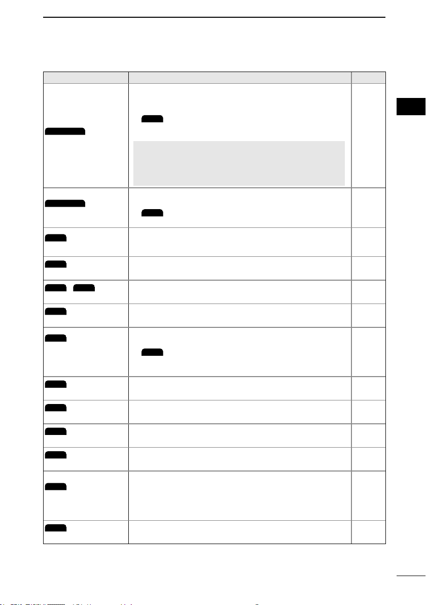
D Software key functions
DISTRESS
DTRS
OTHER DSC
OTH
TASK
SCAN
DW
TW
HI/LO
CH/WX
CHAN
LO/DX
AQUA
NAME
BKLT
LOG
Key Function
Push to display the “Distress” screen to select the nature
ofdistress,thenpushthe[DISTRESS](redkey)tomake
a call.
L
the USA version)
Distress
Other DSC
Task
Scan
/
Dualwatch / Tri-watch
High/Low
Channel/
Weather channel
Low/DX
AquaQuake
Favorite channel
NEVER MAKE A DISTRESS CALL IF YOUR SHIP
OR A PERSON IS NOT IN AN EMERGENCY. A
DISTRESS CALL SHOULD BE MADE ONLY WHEN
IMMEDIATE HELP IS NEEDED.
Push to compose an Individual call, Group call, All Ships
call or a Test call.
L
the USA version)
(For only the USA version)
Displayed only in the Multiple-task mode.
Push to display the task list.
Push to start or stop a Normal or Priority scan.
Push to start or stop Dualwatch or Tri-watch.
Push to set the output power to high or low.
Some channels are set to only low power.
Push to select regular channels or Weather channels.
L The Weather channel is for only the USA version.
L While the Call channel or Channel 16 is displayed, push
this key to return to the regular channel mode.
(For only the USA version)
Push to turn the Attenuator ON or OFF.
Hold down to turn ON the AquaQuake function to clear
water from the speaker grill.
Push to set or release the displayed channel as a
Favorite channel.
PANEL DESCRIPTION
is displayed in the Multiple-task mode. (For only
is displayed in the Multiple-task mode. (For only
is displayed for other versions.
2
Reference
p. 18
p. 20
p. 34
p. 13
p. 14
p. 19
p. 8
—
p. 11
p. 13
1
2
3
4
5
6
7
8
9
10
11
12
13
14
15
16
17
18
Channel Name
Backlight
LOG
Push to edit the name of the displayed channel.
Push to display the backlight brightness adjustment
screen.
L Whileintheadjustmentmode,push[▲]/[▼][◄]/[►]to
adjust the brightness of the display and keys’ backlight to
between 1 and 7, or OFF.
Push to display the received call log or distress message
log.
p. 11
p. 9
p. 33
5
Page 16
3
FIN
FIN
PREPARATION
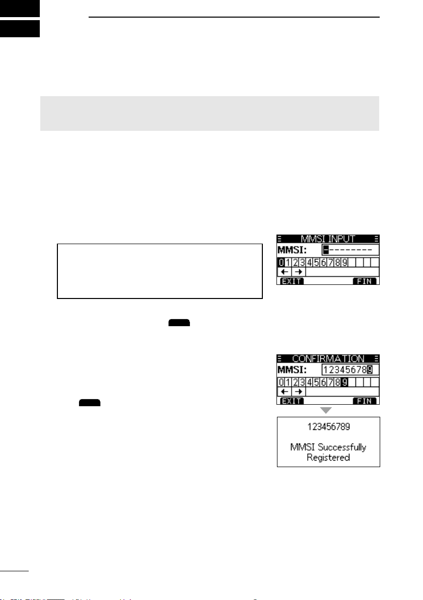
■ Entering the MMSI code
The Maritime Mobile Service Identity (MMSI: DSC self ID) code consists of 9 digits.
You can only enter the code when turning ON the transceiver for the rst time.
This initial code can be entered only once.
After entering, it can be changed only by your dealer or distributor.
If your MMSI code has already been entered, doing the steps below is not necessary.
1. Hold down [PWR] to turn ON the transceiver.
• Three short beeps sound, and “Push [ENT] to Register
your MMSI” is displayed.
2. Push [ENT] to start entering the MMSI code.
• The “MMSI Input” screen is displayed.
L Push [CLR] twice to skip the entry.
If you skip the entry, you cannot make a DSC call. To
enter the code after skipping, turn OFF the power, and
then turn it ON again.
3. Enter the MMSI code.
TIP:
• Select a number using [◄] and [►].
• Push [ENT] to enter the selected number.
• Select “←” or “→” on the screen to move the
cursor.
4. Repeat step 3 to enter all 9 digits.
5. Push the software key below
code.
• The “Conrmation” screen is displayed.
6. Enter your MMSI code again to confirm.
to set the entered
7. Push
• When your MMSI code is successfully entered, “MMSI
Successfully Registered” is briey displayed, and then
enters the operating screen.
L Your MMSI code is also displayed on the opening screen.
to set the entered code.
6
Page 17
■ Selecting a channel
CHAN
CH/WX
CHAN
CH/WX
CHAN
CH/WX
CHAN
CH/WX
EXIT
BASIC OPERATION
4
D Regular Channel
You can select a channel by pushing [▲] or [▼].
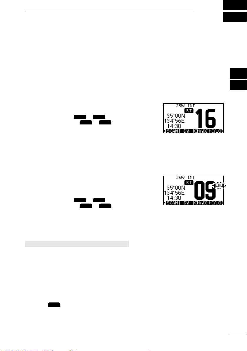
D Channel 16
Channel 16 is the distress and safety channel. It is used to establish the initial contact
with a station, and for emergency communications. Channel 16 is monitored during both
Dualwatch and Tri-watch. While in the standby mode, you must monitor Channel 16.
z Push [16/C] to select Channel 16.
L To return to the previously selected channel, push [◄]
or [►] to display
software key below
or
, and then push the
or
.
D Call channel
Each Channel Group has separate leisure-use Call channels.
The Call channel is scanned during Tri-watch. The Call channels can be selected and
used to store your most often used channels in each Channel Group, for quick recall.
See page 10 for details on setting the Call channel.
z Hold down [16/C] for 1 second to select the Call
channel.
• The Call channel number and “CALL” are displayed.
L To return to the previously selected channel, push [◄]
or [►] to display
software key below
or
, and then push the
or
.
D Selecting a Channel Group
Channel Groups are preset into your transceiver. You can select a Channel Group for
USA, International, and Canadian, depending on the transceiver version.
[MENU] > Radio Settings > Channel Group
1. Push [MENU].
• The Menu screen is displayed.
2. Push [▲] or [▼] to select “Radio Settings,” and then
push [ENT].
3. Push [▲] or [▼] to select “Channel Group,” and then
push [ENT].
• The “CHANNEL GROUP” screen is displayed.
4. Push [▲] or [▼] select a Channel Group, and then
push [ENT].
5. Push
6. The selected Channel Group’s icon is displayed on
the operating screen.
to exit the Menu screen.
1
2
3
4
5
6
7
8
9
10
11
12
13
14
15
16
17
18
7
Page 18
4
CH/WX
BASIC OPERATION
■ Weather channels and Weather Alert
The USA version transceiver has 10 preset Weather channels.
The transceivers are capable* of monitoring broadcasts from the National Oceanographic
and Atmospheric Administration (NOAA). The transceiver automatically detects a Weather
alert tone on the selected weather channel, or while scanning.
*When used within range of the broadcasts.
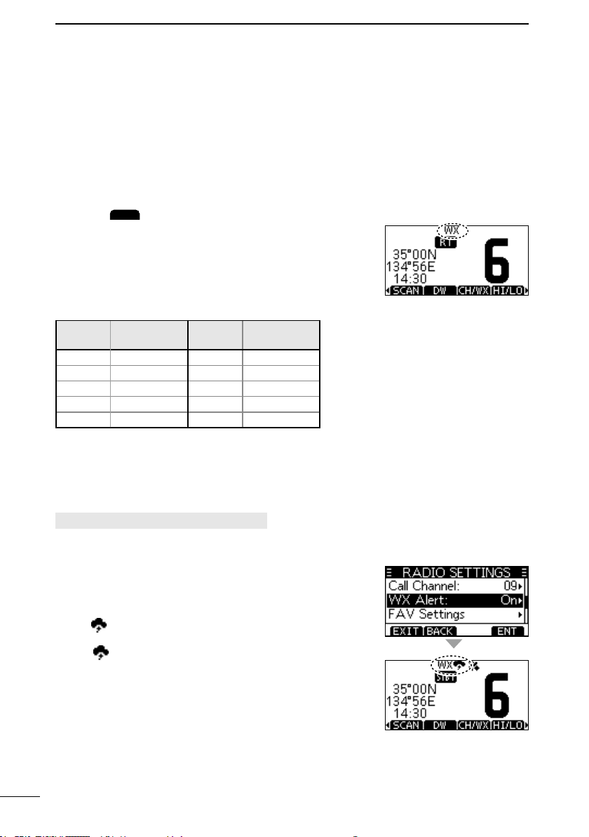
D Selecting a Weather channel
1. Push
• “WX” is displayed on the operating screen instead of
the Channel Group.
2. Push [▲] or [▼] to select a Weather channel.
The Weather channel list
WX
channel
1 162.550 6 162.500
2 162.400 7 162.525
3 162.475 8 161.650
4 162.425 9 161.775
5 162.450 10 163.275
.
Frequency
(MHz)
WX
channel
Frequency
(MHz)
D Setting the Weather Alert
To receive the weather alert, set the WX Alert to “On with
Scan” or “On.”
[MENU] > Radio Settings > WX Alert
1. Push [MENU].
2. Push [▲] or [▼] to select “Radio Settings,” and then
push [ENT].
3. Select “WX Alert,” and then push [ENT].
• The “WX Alert” screen is displayed.
4. Select “On with Scan” or “On.”
• “ ” is displayed next to the weather channel icon.
” blinks until you push a key after detecting an
L “WX
alert.
8
Page 19
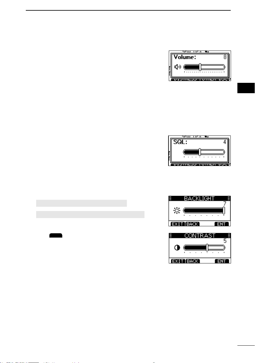
■ Adjusting the volume level
EXIT
1. Push [VOL].
• The volume adjustment screen is displayed.
2. Push [▲], [▼], [◄], or [►] to adjust the audio volume
level.
L If no key is pushed for 5 seconds, the screen
automatically closes.
BASIC OPERATION
4
1
2
3
4
■ Adjusting the squelch level
Squelch enables the audio to be heard only while receiving a signal that is stronger than
the set level. A higher level blocks weak signals, so that you can receive only stronger
signals. A lower level enables you to hear weak signals.
1. Push [VOL] twice.
• The squelch level adjustment screen is displayed.
2. Push [▲], [▼], [◄], or [►] to adjust the squelch level.
L If no key is pushed for 5 seconds, the screen
automatically closes.
■ Adjusting the backlight or the display contrast
1. Open the “BACKLIGHT” or “CONTRAST” screen.
[MENU] > Conguration > Backlight
[MENU] > Conguration > Display Contrast
2. Push [▲], [▼],
[ENT] to set.
3. Push
[◄], or [►] to adjust, and then push
to exit the Menu screen.
5
6
7
8
9
10
11
12
13
14
15
16
17
18
9
Page 20
4
EXIT
BASIC OPERATION
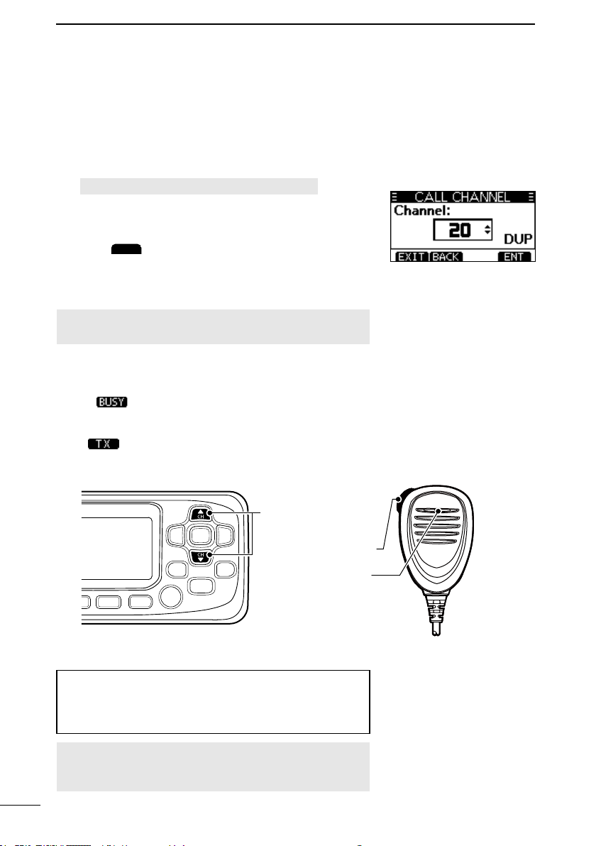
■ Setting the Call channel
By default, a Call channel is set in each Channel Group.
You can set your most often-used channel as your Call channel in each Channel Group
for quick recall.
1. Open the “CALL CHANNEL” screen.
[MENU] > Radio Settings > Call Channel
2. Push [▲] or [▼] to select the channel.
3. Push [ENT] to set the selected channel as the Call
channel.
4. Push
to exit the Menu screen.
■ Receiving and transmitting
CAUTION: Transmitting without an antenna may
damage the transceiver.
1. Push [▲] or [▼] to select the channel to call on.
• The channel number and name are briey displayed.
(Only when “CH Close-up” is ON.)
L
is displayed while receiving a signal.
2. Hold down [PTT] and speak into the microphone at
your normal voice level.
• is displayed while transmitting.
3. Release [PTT] to receive.
1Select a channel
2Hold down [PTT]
and speak into
the microphone
3Release [PTT] to
receive
TIP: To maximize the readability of your transmitted
signal, pause for a second after holding down [PTT] and
hold the microphone 5 to 10 cm (2 to 4 inches) from your
mouth, and then speak at your normal voice level.
NOTE: The Time-out Timer function cuts OFF
transmission after 5 minutes of continuously transmitting,
to prevent prolonged transmission.
10
Page 21

BASIC OPERATION
AQUA
AQUA
AQUA
NAME
NAME
FIN
123
!$?
4
■ AquaQuake Water Draining function
Water in the speaker grill may mufe the sound coming from the speaker. The
AquaQuake Water Draining function removes water from the speaker grill by vibrating the
speaker cone.
CAUTION: DO NOT use the AquaQuake Water Draining function when an external
speaker is connected.
1
2
3
1. Push [◄] or [►] to display
2. Hold down
• A low frequency vibration beep sounds to drain the
water, regardless of the volume level setting.
L This function is activated for a maximum of 10
seconds, even if you continue to hold down
3. Release the key to turn OFF the function.
to turn ON the function.
.
.
■ Editing a channel name
You can edit the name of each operating channel and weather channel, using numbers,
uppercase letters, symbols, and a space. This enables easy recognition of the channels
or stations. All VHF marine channels are set with default names.
L You can edit channel names only when the “CH Close-up” is set to ON.
[MENU] > Radio Settings > CH Close-up
1. Push [▲] or [▼] to select the channel to edit.
2. Push [◄] or [►] to display
L You cannot edit a channel name during Dualwatch,
Tri-watch, or a scan.
3. Push
• The “CHANNEL NAME” screen is displayed.
4. Edit the channel name.
5. Push
operating screen.
TIP:
• Push
.
to save the edited name and return to the
to display numbers, or
.
to display characters.
4
5
6
7
8
9
10
11
12
13
14
15
16
17
18
• Select characters or space using [▲]/[▼]/[◄]/[►].
• Select “◄” or “►” on the screen to scroll.
• Push [ENT] to enter the selected character.
• Select “←” or “→” on the screen to move the cursor.
11
Page 22

5
SCAN OPERATION
■ Scan types
You can nd ongoing communication by scanning the Favorite channels.
Before starting a scan :
• Set the channels that you want to scan as Favorite channels. (p. 13)
L Only the Favorite channels are scanned.
• Set the scan type to “Priority Scan” or “Normal Scan” on the “Radio Settings” screen.
(p. 41)
[MENU] > Radio Settings > Scan Type
Normal Scan
Sequentially searches through all Favorite channels. Channel 16 is not scanned unless it
is set as a Favorite channel.
CH 04
CH 03
CH 02
CH 01
Priority Scan
Sequentially searches through all Favorite channels, while also periodically checking
Channel 16.
CH 04
CH 03
CH 16
CH 02
CH 01
When a signal is received:
On Channel 16: The scan pauses until the signal disappears.
On a channel other than Channel 16: The scan becomes Dualwatch until the signal
CH 05
WX*
CH 05
WX*
* For the USA version. When the Weather
Alert function is ON, the previously
selected Weather channel is also scanned.
* For the USA version. When the Weather
Alert function is ON, the previously
selected Weather channel is also scanned.
disappears.
12
Page 23

■ Setting Favorite channels
SCAN
SCAN
SCAN
SCAN OPERATION
5
You can quickly recall often-used channels by setting them as Favorite channels. You can
set Favorite channels in each Channel Group.
1. Select a Channel Group on the Menu screen. (p. 7)
[MENU] > Radio Settings > Channel Group
2. Push [▲] or [▼] to select the channel.
3. Push [◄] or [►] to display
4. Push
• The selected channel is set as a Favorite channel, and “ ” is displayed.
L To cancel the setting, push
TIP: You can set all channels as Favorite channels, clear all settings, or reset to the
defaults. By default, some channels are preset as Favorite channels. The preset
channels differ, depending on the transceiver version.
.
.
again.
■ Starting a scan
Example: Starting a Normal Scan.
1. Select a Channel Group on the Menu screen. (p. 7)
[MENU] > Radio Settings > Channel Group
2. Push [◄] or [►] to display
3. Push
• The scan starts.
• “ ” is displayed during a Normal Scan, and
“ ” is displayed during a Priority Scan.
• “ ” and “ ” are displayed when a signal is
received.
L When a signal is received, the scan pauses until it
disappears, or resumes after 5 seconds, depending
on the Scan Timer setting in “Radio Settings.”
L A beep sounds and “16” blinks when a signal is
received on Channel 16 during a Priority scan.
4. To stop the scan, push
TIP: To properly receive signals, be sure to adjust the
squelch to a suitable level.
.
.
.
1
2
3
4
5
6
7
8
9
10
11
12
13
14
15
16
17
18
13
Page 24

6
DW
TW
DW
TW
DW
TW
DUALWATCH/TRI-WATCH
■ Description
Dualwatch and Tri-watch are convenient to periodically check Channel 16 while you are
operating on another channel.
Dualwatch
Operating
channel
CH 16
Tri-watch
Call
channel
Operating
channel
CH 16
Periodically checks Channel
16 while operating on another
channel.
When a signal is received:
On Channel 16: Dualwatch/Tri-watch pauses on Channel 16 until the signal
disappears.
On the Call channel: Tri-watch switches to Dualwatch until the signal on the Call
channel disappears.
Periodically checks Channel 16 and
the Call channel while operating on
another channel.
■ Operation
1. Select Dualwatch or Tri-watch on the Menu screen.
[MENU] > Radio Settings > Dual/Tri-Watch
2. Push [▲] or [▼] to select a channel.
3. Push [◄] or [►] to display
4. Push
5. To cancel Dualwatch or Tri-watch, push
(Tri-watch).
• Dualwatch or Tri-watch starts.
• “
displayed for Tri-watch.
L “
the Call channel.
L A beep sounds and “ ” blinks when a signal is
received on Channel 16.
or
” is displayed for Dualwatch, or “ ” is
” is displayed when a signal is received on
again.
.
(Dualwatch) or
or
14
Page 25

DIGITAL SELECTIVE CALLING (DSC)
ADD
FIN
123
!$?
FIN
■ DSC address ID
7
D Entering an Individual or Group ID
You can enter a total of 60 Individual IDs and 30 Group IDs, and assign names to them of
up to 10 characters.
1. Open the “INDIVIDUAL ID” or “Group ID” screen.
[MENU] > DSC Settings > Individual ID
[MENU] > DSC Settings > Group ID
• “No ID” is displayed if no ID is entered.
2. Push
• The ID entry screen is displayed.
3. Enter an Individual or Group ID.
TIP:
• Select a number using [◄]/[►].
• Push [ENT] to set the selected number.
• Select “←” or “→” on the screen to move the cursor.
NOTE:
• For a Group ID, the rst digit is xed as “0.”
• For any coast station ID, the rst two digits are
xed as “0.”
4. Push
• The name entry screen is displayed.
5. Enter the ID’ s name.
TIP:
• Push
use characters and letters.
.
.
to use numbers, and push
to
1
2
3
4
5
6
7
8
9
10
11
12
13
14
15
16
• Select characters or space using [▲]/[▼]/[◄]/[►].
• Select “◄” or “►” on the screen to scroll.
• Push [ENT] to enter the selected character.
• Select “←” or “→” on the screen to move the
cursor.
6. After entering, push
previous screen.
• The entered name is displayed.
to save, and return to the
17
18
15
Page 26

7
DEL
OK
CANCEL
EDIT
FIN
FIN
EXIT
DIGITAL SELECTIVE CALLING (DSC)
D Deleting an entered ID
(Example: Deleting an Individual ID: STATION 2)
1. Open the “INDIVIDUAL ID” screen.
[MENU] > DSC Settings > Individual ID
2. Select “STATION 2,” and then push
• “Are You Sure?” is displayed.
3. Push
L Push
• The selected ID is deleted, and then returns to the
previous screen.
to delete.
to cancel the deletion.
.
TIP: You can edit an ID and its name by pushing
in step 2.
■ Entering the position and time
A Distress call should include the vessel’s position, date, and time. If no GPS data is
received, manually enter the position and Universal Time Coordinated (UTC) time.
NOTE:
• The manual entry is disabled while valid GPS data is received.
• The manually entered position and time is valid only for 23.5 hours, or until turning
OFF the transceiver.
1. Open the “POSITION INPUT” screen.
[MENU] > DSC Settings > Position Input
2. Enter the latitude.
TIP:
• Select a number or a compass direction using [▲]/
[▼]/[◄]/[►].
• Select “←” or “→” on the screen to move the
cursor.
• Push [ENT] or
3. Enter the longitude and the UTC time.
L See the TIP in step 2 to enter.
4. Push
5. Push
• The “DSC Settings” screen is displayed.
to set the entered position and time.
to return to the standby screen.
to save the selected number.
16
Page 27

DIGITAL SELECTIVE CALLING (DSC)
ALARM OFF
CANCEL
■ Sending DSC calls (Distress)
A Distress call should be sent if, in the opinion of the captain, the ship or a person is in
distress and requires immediate assistance.
NEVER MAKE A DISTRESS CALL IF YOUR SHIP OR A PERSON IS NOT IN AN
EMERGENCY. A DISTRESS CALL SHOULD BE MADE ONLY WHEN IMMEDIATE
HELP IS NEEDED.
7
1
2
3
D Simple call
1. Confirm that no Distress call is being received.
2. While lifting up the key cover, hold down [DISTRESS]
for 3 seconds until you hear 3 short countdown beeps
and a long beep sound.
• The backlight blinks.
Key cover
3. After sending, wait for an Acknowledgment call.
• “Waiting for ACK” is displayed.
• The Distress call is automatically sent every 3.5 to 4.5
minutes, until an Acknowledgement is received, or a
Distress Cancel call is sent.
4. When you receive an Acknowledgment, an alarm
sounds. Push
• Channel 16 is automatically selected.
5. Hold down [PTT], and then explain your situation.
6. After you have finished your conversation, push
to return to the operating screen.
to turn OFF the alarm.
4
5
6
7
8
9
10
11
12
13
14
15
16
17
18
TIP: A default Distress alert contains:
• Nature of distress: Undesignated distress
• Position information: The latest GPS, or manually input position, that is held for 23.5 hours,
or until you turn OFF the transceiver.
17
Page 28

7
DISTRESS
ALARM OFF
DIGITAL SELECTIVE CALLING (DSC)
D Regular call
Select the nature of the Distress call to include in the Regular Distress call.
1. Push
• The “DISTRESS” screen is displayed.
2. Push [ENT] to enter the Nature selection mode.
3. Select the nature of the Distress, and then push
[ENT]. (Example: Flooding)
• The setting is saved and returns to the previous screen.
L If no valid GPS data is being received, select
“Position,” and then enter the latitude, longitude, and
UTC.
See “Entering the position and time” on page 16 for
details.
4. While lifting up the key cover, hold down [DISTRESS]
(the red button) for 3 seconds until you hear 3 short
countdown beeps and a long beep sound.
•
The backlight blinks.
5. After sending, wait for an Acknowledgment.
• “Waiting for ACK” is displayed.
L The Distress call is automatically sent every 3.5 to 4.5
minutes, until an Acknowledgment is received, or a
Distress Cancel call is sent. (p. 19)
6. When you receive an Acknowledgment, an alarm
sounds. Push
• Channel 16 is automatically selected.
7. Hold down [PTT] to communicate.
TIP: You can also send a Regular call by selecting the
“Distress” item on the Menu screen.
.
to turn OFF the alarm.
18
Page 29

DIGITAL SELECTIVE CALLING (DSC)
CONTINUE
FINISH
STBY
CANCEL
RESEND
PAUSE
INFO
STBY
INFO
HIST
HI/LO
D Distress Cancel call
If you have accidentally made a Distress call, or made an incorrect Distress call, send a
Distress Cancel call to cancel the call as soon as possible while waiting for an
Acknowledgement. Be sure to report the purpose of the cancellation.
1. While waiting for an Acknowledgement, push
• The screen to the right is displayed.
2. Push
• The Distress Cancel call is sent.
• Channel 16 is automatically selected.
3. Hold down [PTT] to report the purpose of the
cancellation.
L You can display the wording of the cancellation by
pushing [▼].
4. After communicating, push
L The screen to the right is displayed.
.
.
CANCEL
.
7
1
2
3
4
5
6
7
8
9
10
11
12
5. Push
• Returns to the operating screen.
to finish the Distress Cancel call.
D Distress call Software Key description
While waiting for an Acknowledgement:
: Cancels the Distress call and
enables you to send a Cancel call.
: Enables you to resend the
Distress call by holding down
[DISTRESS] again.
: Pauses the countdown to resend
the next Distress call.
: Displays the information of the
Distress call that you have sent.
After receiving an Acknowledgement:
: Closes the Distress operation, and
returns to the operating screen.
: Displays the information
of the received Distress
Acknowledgement.
: Displays the “DISTRESS
HISTORY.”
Changes the output power.
13
14
15
16
17
18
19
Page 30

7
OTHER DSC
CALL
ALARM OFF
ALARM OFF
STBY
OK
DIGITAL SELECTIVE CALLING (DSC)
■ Sending DSC calls (other)
NOTE: To ensure proper DSC operation, be sure to correctly adjust the “CH 70 SQL
Level” item on the Menu screen. (p. 37)
D Sending an Individual call
An Individual call enables you to send a DSC signal to only a specic station. You can
communicate after receiving the Acknowledgement “Able to comply.”
1. Push
• The “OTHER DSC” screen is displayed.
L You can also display the “OTHER DSC” screen by
selecting the “Other DSC” item on the Menu screen.
2. Select “Type,” and then push [ENT].
3. Select “Individual Call,” and then push [ENT].
• Returns to the “OTHER DSC” screen.
4. Select “Address,” and then push [ENT].
5. Select the station to send an Individual call to, and
then push [ENT].
• Returns to the “OTHER DSC” screen.
L You can also select “Manual Input” to manually enter
the target station ID.
6. Select “Channel,” and then push [ENT].
7. Select a channel to assign, and then push [ENT].
L The assigned channels are preset by default.
8. Push
•
“Transmitting Individual Call” is displayed, and then
“Waiting for ACK” is displayed.
L If Channel 70 is busy, the transceiver stands by until
the channel becomes clear.
.
to send the Individual call.
9. When you receive an Acknowledgement “Able to
10. Push
11. Hold down [PTT] to communicate.
20
comply”:
• An alarm sounds.
• The screen to the right is displayed.
• The channel assigned in step 7 is automatically
selected.
L If the called station cannot use the channel that you
assigned, a different channel is selected by the other
station.
TIP: If you received an Acknowledgement “Unable to comply”:
1. Push
• The Acknowledge information is displayed.
2. Push
to turn OFF the alarm.
to turn OFF the alarm.
, and then
to return to the operating screen.
Page 31

DIGITAL SELECTIVE CALLING (DSC)
ALARM OFF
ACPT
ABLE
IGN
ABLE, UNABLE
NEW CH
ABLE
UNABLE
NEW CH
CALL
D Sending an Individual Acknowledgement
When you have received an Individual call (p. 29), send an Acknowledgement to the
calling station. When the Auto Ack is set to “Manual,” you can select an appropriate
acknowledgement type.
1. While an Individual call is being received, push
• The received call’s information is displayed.
2. Push
• The Acknowledgement category screen is displayed.
L If you want to send an Acknowledgement “Able to
L If you cannot communicate, and want to return to the
3. Push
Acknowledgement type.
(Able to
Comply)
(Unable to
Comply):
(Propose
New CH)
to turn OFF the alarm.
.
comply” right away, push
operating screen, push
, or
Sends an Acknowledgement without any
:
changes.
Sends an Acknowledgement but cannot
:
communicate.
Able to communicate but proposes
:
another channel. Specify the channel by
pushing [▲] or [▼].
(Example: Channel 69)
.
.
to select the
7
1
2
3
4
5
6
7
8
9
10
11
12
13
14
4. Push
to send the Acknowledgement.
15
16
17
18
21
Page 32

7
OTHER DSC
CALL
DIGITAL SELECTIVE CALLING (DSC)
D Sending an All Ships call
All Ships that have DSC transceiver use Channel 70 as their listening channel. When you
want to announce a message to these ships, if they are within range, use the All Ships
Call.
1. Push
• The “OTHER DSC” screen is displayed.
L You can also display the “OTHER DSC” screen by
selecting the “Other DSC” item on the Menu screen.
2. Select “Type,” and then push [ENT].
• The “MESSAGE TYPE” screen is displayed.
3. Select “All Ships,” and then push [ENT].
• The All Ships call is selected, and returns to the
“OTHER DSC” screen.
4. Select “Category,” and then push [ENT].
• The “CATEGORY” screen is displayed.
5. Select a category of the call, and the push [ENT].
• The category is set, and returns to the “OTHER DSC”
screen.
6. Select “Channel,” and then push [ENT].
7. Select the channel to assign, and then push [ENT].
L The assigned channels are preset by default.
8. Push
• “Transmitting All Ships Call” is displayed, and then the
assigned channel is automatically selected.
L If Channel 70 is busy, the transceiver stands by until
the channel becomes clear.
9. Hold down [PTT] to communicate.
.
to send the All Ships call.
22
Page 33

DIGITAL SELECTIVE CALLING (DSC)
OTHER DSC
CALL
D Sending a Group call
A Group call enables you to send a DSC call to only a specic group.
L You can send a Group call to a pre-entered group address, or manually enter the address
before sending. (p. 15)
1. Push
• The “OTHER DSC” screen is displayed.
L You can also display the “OTHER DSC” screen by
selecting the “Other DSC” item on the Menu screen.
2. Select “Type,” and then push [ENT].
• The “MESSAGE TYPE” screen is displayed.
3. Select “Group,” and then push [ENT].
• The Group call is selected, and returns to the “OTHER
DSC” screen.
4. Select “Address,” and then push [ENT].
• The “ADDRESS” screen is displayed.
5. Select the group to send a Group call, and then push
[ENT].
L You can also select “Manual Input” to manually enter
the target group.
6. Select “Channel,” and then push [ENT].
7. Select the channel to assign, and then push [ENT].
L The assigned channels are preset by default.
.
7
1
2
3
4
5
6
7
8
9
10
11
12
8. Push
• “Transmitting Group Call” is displayed, and then the
assigned channel is automatically selected.
L If Channel 70 is busy, the transceiver stands by until
the channel becomes clear.
9. Hold down [PTT] to communicate.
to send the Group call.
13
14
15
16
17
18
23
Page 34

7
OTHER DSC
CALL
ALARM OFF
CLOSE
STBY
DIGITAL SELECTIVE CALLING (DSC)
D Sending a Test call
You should avoid testing calls on the exclusive DSC Distress channels and safety calling
channels. When you cannot avoid testing on a Distress or safety channel, you should
indicate that these are test calls.
Normally the Test call would require no further communications between the two stations
involved.
1. Push
• The “Other DSC” screen is displayed.
L You can also display the “Other DSC” screen by
selecting the “Other DSC” item on the Menu screen.
2. Select “Test,” and then push [ENT].
• The Test call is selected, and returns to the “OTHER
DSC” screen.
3. Select “Address,” and then push [ENT].
• The “ADDRESS” screen is displayed.
4. Select a station to send the Test call to.
L You can also select “Manual Input” to manually enter
the calling station.
5. Push
L If Channel 70 is busy, the transceiver stands by until
the channel becomes clear.
6. When you receive an Acknowledgement:
• An alarm sounds.
• The screen to the right is displayed.
7. Push
• The Acknowledgement information is displayed.
8. Push
• The received call’s information is displayed.
• The call is saved in the DSC Log.
9. Push
.
to send the Test call.
to turn OFF the alarm.
.
to return to the operating screen.
24
Page 35

DIGITAL SELECTIVE CALLING (DSC)
ALARM OFF
ACPT
ACK
CALL
STBY
OK
D Sending a Test Acknowledgement
By default, when you receive a Test call, the Auto ACK function automatically sends an
Acknowledgement to the calling station (p. 36). If the function is set to “Manual,” do the
following steps to send an Acknowledgement.
1. After a Test call is being received, push
turn OFF the alarm.
2. Push
• The received call’s information is displayed.
.
to
7
1
2
3
4
3. Push
• The “Test ACK” conrmation screen is displayed.
4. Push
• “Transmitting Test ACK” is displayed.
5. Push
operating screen.
.
to send the Acknowledgement.
, and then push
to return to the
5
6
7
8
9
10
11
12
13
14
15
16
17
18
25
Page 36

7
OTHER DSC
CALL
ALARM OFF
CLOSE
STBY
OK
DIGITAL SELECTIVE CALLING (DSC)
D Sending a Position Request call/Polling Request call
(For only the USA version)
You can send a Position Request call or Polling request call to a station, depending on
the presetting.
Send a Position Request call when you want to know a specic ship’s current position.
Example: Sending a Position Request call
1. Push
• The “OTHER DSC” screen is displayed.
L You can also display the “OTHER DSC” screen by
selecting the “Other DSC” item on the Menu screen.
2. Select “Type,” and then push [ENT].
3. Select “Position,” and then push [ENT].
L When you send a Polling Request call, select
“Polling.”
• The message type is selected, and returns to the
“OTHER DSC” screen.
4. Select “Address,” and then push [ENT].
5. Select a target to send a Position Request call to, and
then push [ENT].
L You can also select “Manual Input” to manually enter
the target ID.
6. Push
• Position Request call is sent, and then “Waiting for
ACK” is displayed.
L If Channel 70 is busy, the transceiver stands by until
the channel becomes clear.
.
to send the Position Request call.
7. When you receive a Position Reply:
8. Push
9. Push
10. Push [▲] or [▼] to scroll the screen, and then check
11. Push
26
• An alarm sounds.
• The screen to the right is displayed.
to turn OFF the alarm.
• The received information is displayed.
the targetʼs position.
screen.
.
, and then
to return to the operating
Page 37

DIGITAL SELECTIVE CALLING (DSC)
ALARM OFF
ACPT
ABLE
UNABLE
CALL
STBY
OK
7
D Sending a Position Reply call
Send a Position Reply call when a Position Request call is received.
If the Auto ACK function is set to “Auto,” the Acknowledgement is automatically sent to the
calling station. (p. 36)
1. While a Position Request call is being received, push
2. Push
• The received call’s information is displayed.
to turn OFF the alarm.
.
1
2
3
4
5
3. Push
Acknowledgement, or push
to Comply” Acknowledgement.
L If no valid GPS position is received, you can manually
enter the position and time in “Position” item on this
screen. See “Entering the position and time” on page
16 for details.
4. Push
5. Push
screen.
to send an “Able to Comply”
to send an “Unable
to send the Position Reply call.
, and then
to return to the operating
6
7
8
9
10
11
12
13
14
15
16
17
18
27
Page 38

7
ALARM OFF
IGN
PAUSE
PAUSE
RESUME
ACPT
STBY
DIGITAL SELECTIVE CALLING (DSC)
■ Receiving DSC calls (Distress)
The transceiver receives Distress calls, Distress Acknowledgements, and Distress Cancel
calls.
When you receive a call, an emergency alarm sounds.
NOTE: The screens that are displayed when a Distress call or an Acknowledgement
is received slightly differ from one another. The following steps are described using an
example of receiving a Distress call.
When a Distress call is received:
• The emergency alarm sounds until you turn it OFF.
• “RCVD DISTRESS” is displayed.
1. Push
2. Push the Software Key below the intended operation.
:
(Ignore)
:
(Pause)
:
(Accept)
to turn OFF the alarm.
Returns to the operating screen.
The call is saved in the DSC Log.
“
” blinks continuously until you display
the call message.
is not displayed if the “CH Auto SW”
item is set to “Manual.” (p. 36)
Pauses the countdown until the assigned
channel is automatically selected.
Select
The call is saved in the DSC Log.
Accepts the call.
Channel 16 is automatically selected.
Monitor Channel 16 as a coast station
may require assistance.
After Channel 16 is selected, select your
next operation by pushing the Software
Key below the following options.
INFO
HIST
to resume the countdown.
: Returns to the operating screen.
: Displays the information of the
received Distress call.
: Displays the “DISTRESS
HISTORY” screen.
28
Page 39

DIGITAL SELECTIVE CALLING (DSC)
ALARM OFF
IGN
ABLE
RESEND
ACPT
ABLE
UNABLE
NEW CH
7
■ Receiving DSC calls (other)
The transceiver receives the following types of DSC calls.
• Individual call (p. 29)
• Individual Acknowledgement (p. 21)
• Group call (p. 30)
• All Ships call (p. 30)
• Position Request call (p. 31)
• Test call (p. 32)
• Test Acknowledgement (p. 24)
L The receivable call types may differ, depending on the transceiver version or presetting.
By default, the Auto ACK function automatically sends an Acknowledgement to the calling
station. ( [MENU] > DSC Settings > Auto ACK (p. 36))
If Auto ACK is set to “Manual,” you can manually send an Acknowledgement for each call
as described in this section.
D Receiving an Individual call
When an Individual call is received:
• An alarm sounds.
• “RCVD INDIVIDUAL” is displayed.
1. Push
to turn OFF the alarm.
1
2
3
4
5
6
7
8
9
10
11
2. Push the Software Key below the next operation.
Ignores the call and returns to the operating
:
(Ignore)
( Able to
comply)
(Accept)
screen.
• The call is saved in the DSC Log.
• “
” blinks continuously until you display
the call message.
Sends an Individual Acknowledgement right
:
away.
• Automatically switches to the assigned
channel.
• After sending, push
• The call is saved in the DSC Log.
Accepts the call.
:
• The call is saved in the DSC Log.
• The received call’s information is
displayed.
• Push the Software Key to select the
Acknowledgement option.
:
(Able to Comply)
:
(Unable to Comply)
:
(Propose New CH)
to resend.
Sends an Acknowledgement without any changes.
Sends an Acknowledgement but cannot
communicate.
Able to communicate but proposes another channel.
Specify the channel by pushing [▲] or [▼].
12
13
14
15
16
17
18
29
Page 40

7
ALARM OFF
IGN
PAUSE
RESUME
PAUSE
ACPT
STBY
INFO
DIGITAL SELECTIVE CALLING (DSC)
D Receiving a Group call or All Ships call
When a Group call is received:
• An alarm sounds.
• “RCVD GROUP CALL” is displayed.
When an All Ships call is received:
• An alarm sounds.
• “RCVD ALL SHIPS” is displayed.
( Example: when a Group
call is received)
1. Push
• The channel that is assigned by the caller is
automatically selected after 10 seconds by default.
2. Push the Software Key below your next operation.
:
(Ignore)
:
(Pause)
:
(Accept)
to turn OFF the alarm.
Ignores the call and returns to the operating
screen.
• The call is saved in the DSC Log.
• “
” blinks continuously until you display
the call message.
Pauses the countdown until the assigned
channel is automatically selected.
• Select
• The call is saved in the DSC Log.
L
item is set to “Manual.” (p. 36)
Accepts the call.
• The assigned channel is selected.
• The call is saved in the DSC Log.
: Closes the call, and then returns to
: The received call’s information is
to resume the countdown.
is not displayed if the “CH Auto SW”
the operating screen.
displayed.
30
Page 41

DIGITAL SELECTIVE CALLING (DSC)
ALARM OFF
IGN
ABLE
UNABLE
EXIT
ACPT
ABLE
UNABLE
CALL
D Receiving a Position Request call
(May not be used, depending on the presetting)
NOTE: Even if the Auto ACK function is set to “Manual,” after receiving a Distress
Acknowledgement, or while in the Distress Cancel call procedure, the Position Reply is
automatically sent to the calling station.
When a Position Request call is received:
• An alarm sounds.
• “RCVD POS Request” is displayed.
1. Push
to turn OFF the alarm.
7
1
2
3
4
5
6
2. Push the Software Key below the intended operation.
Ignores the call and returns to the
:
(Ignore)
( Able to
comply)
(Unable to
Comply)
(Accept)
operating screen.
• The call is saved in the DSC Log.
• “
” blinks continuously until you display
the call message.
Sends Acknowledgement “Able to
:
comply” right away.
Sends an Acknowledgement “Unable to
Comply.”
:
• The call is saved in the DSC Log.
• Displays the Acknowledgement
information, and then returns to the
operating screen by pushing
Accepts the call.
:
• Displays the received call’s information.
• The call is saved in the DSC Log.
Push
send the Position Reply call. (p. 27)
or
, then push
.
to
7
8
9
10
11
12
13
14
15
16
17
18
31
Page 42

7
ALARM OFF
IGN
ABLE
ACPT
ACK
CALL
RESEND
DIGITAL SELECTIVE CALLING (DSC)
D Receiving a Test call
When a Test call is received:
• An alarm sounds.
• “RCVD TEST CALL” is displayed.
1. Push
2. Push the Software Key below your next operation.
:
(Ignore)
:
( Able to
comply)
:
(Accept)
to turn OFF the alarm.
Ignores the call and returns to the operating
screen.
• The call is saved in the DSC Log.
• “
” blinks continuously until you display
the call message.
Sends a Test Acknowledgement “Able to
Comply.”
• The call is saved in the DSC Log.
Accepts the call.
• Displays the received call’s information.
• The call is saved in the DSC Log.
• The received call’s information is
displayed.
Push
Test Acknowledgement. (p. 25)
Push
, and then push
to resend.
to send a
32
Page 43

■ DSC Log
LOG
EXIT
BACK
DEL
MMSI
EXIT
BACK
DEL
MMSI
DIGITAL SELECTIVE CALLING (DSC)
7
D Received DSC Log
The transceiver saves up to 30 received Distress call messages and 50 received “Others”
call messages in your DSC Log.
On the operating screen, “
The icon blinks when there is a new received call message.
1. Open the “DSC Log” screen.
[MENU] > DSC Log
2. Select “Received Call Log,” and then push [ENT].
• The “RCVD CALL LOG” screen is displayed.
3. Select “Distress” or “Others,” and then push [ENT].
L “Distress” displays the received Distress call log, and
“Others” displays the received DSC call log.
TIP: You can also display the “Received” screen by
pushing
4. Select a log, and then push [ENT] to display the
detailed information.
on the operating screen.
: Returns to the operating screen.
: Returns to the previous screen.
: Deletes the selected call log.
: Saves the MMSI as an Individual ID.
” is displayed when there is an unread call message.
D Transmitted DSC Log
The transceiver saves up to 30 DSC transmitted calls in
your DSC Log.
1. Open the “DSC Log” screen.
[MENU] > DSC Log
2. Select “Transmitted Call Log,” and then push [ENT].
• The “TX CALL LOG” screen is displayed.
3. Select a log, and then push [ENT] to display the
detailed information.
1
2
3
4
5
6
7
8
9
10
11
12
13
14
15
16
17
18
: Returns to the operating screen.
: Returns to the previous screen.
: Deletes the selected call log.
: Saves the MMSI as an Individual ID or a
Group ID.
33
Page 44

7
TASK
ALARM OFF
HOLD
TASK
ACTIVE
DEL
DIGITAL SELECTIVE CALLING (DSC)
■ Multiple-task mode
(For only the USA version, depending on the presetting.)
If the Multiple-task function is enabled, the transceiver can hold up to 7 tasks. You can
handle more than 2 DSC tasks simultaneously by switching between the tasks.
To use the Multiple-task mode, select “Multiple” in the “Procedure” on the Menu screen.
(p.37)
[MENU] > DSC Settings > Procedure
When the Multiple-task mode is activated,
NOTE: The Task mode has a Time-out Timer (TOT) function. After a certain period of
time has passed without any operation on a task, the transceiver automatically exits the
Task mode and returns to the operating screen.
When a Time-out Timer activates, an alarm sounds and a count down message is
displayed for 10 seconds.
D Holding a DSC task
In the Multiple-task mode, you can hold or activate the DSC task as follows.
Example: When a Group call is received:
1. Push
• The received call’s information is displayed.
2. Push
• The received Group call task is held into the task list
and returns to the operating screen.
to turn OFF the alarm.
.
is displayed on the operating screen.
1. Push
2. Select the task that you want to activate.
3. Push
4. Push [PTT] to communicate.
5. After finishing the communication, push
34
D Activating the held DSC task
to display the task list.
• The task list is displayed.
to activate the task.
• The activated task information is displayed.
to
delete the task.
Page 45

DIGITAL SELECTIVE CALLING (DSC)
TASK
STBY
INFO
DEL
HOLD
ACTIVE
D Task list
When one or more tasks are held, you can display the task list screen by pushing
The number of tasks is displayed at the top of the screen.
The number of tasks
7
.
1
2
3
On the “TASK LIST” screen, the following Software Keys are displayed.
: Holds the task and returns to the operating screen.
: Displays the task information.
: Finishes the selected task.
: Holds the selected task.
: Activates the selected task.
4
5
6
7
8
9
10
11
12
13
14
15
16
17
18
35
Page 46

7
DIGITAL SELECTIVE CALLING (DSC)
■ DSC Settings
On the “DSC Settings” screen, you can
make settings of the DSC call related
items.
[MENU] > DSC Settings
Position Input
See “Entering the position and time” on
page 16 for details.
Individual ID
See “Entering an Individual ID” on page 15
for details.
Group ID
See “Entering a Group ID” on page 15 for
details.
Auto ACK
The Auto ACK function automatically
sends an Acknowledgement when an
appropriate Request is received.
z Individual ACK
Auto (Able): Automatically sends
Auto (Unable): Automatically sends
Manual: Manually sends an
z Position ACK
Auto (Able): Automatically sends
Manual: Manually sends an
z Polling ACK
Auto: Automatically sends an
Manual: Manually sends an
z Test ACK
Auto: Automatically sends an
Manual: Manually sends an
“Able to comply.”
“Unable to comply.”
Acknowledgement.
“Able to comply.”
Acknowledgement.
Acknowledgement.
Acknowledgement.
Acknowledgement.
Acknowledgement.
CH Auto SW
Select whether or not to automatically
switch to channel 16 or the specied
channel, or ignore the call.
Accept: After receiving a DSC call,
the transceiver remains on
the operating channel for
10 seconds. After that, the
transceiver automatically
switches to the channel that is
specied on the DSC call.
Ignore: After receiving a DSC call, if you
do not push the Software Key
below [ACPT] in 10 seconds,
the transceiver ignores the call,
and then remains on the current
operating channel.
Manual: After receiving a DSC call, you
can select whether or not to
accept the received DSC call.
NOTE: In the Multiple-task mode,
“Accept” is renamed to “Accept after 10
sec.” and “Ignore” is renamed to “Hold
after 10 sec.”
Data Output
When receiving a DSC call from the
station that is selected in this setting, the
transceiver outputs the DSC data to the
NMEA output port.
L You can send Distress calls despite of this
setting.
All Stations: From any station.
Stations List: From the stations that
are entered Individual ID
or Group ID on the Menu
screen.
OFF: Does not output any DSC
data from the NMEA 0183
Output port.
36
Page 47

DIGITAL SELECTIVE CALLING (DSC)
7
Alarm Status
Sets the alarm ON or OFF when receiving
each type of DSC call.
z Safety
z Routine
z Warning
Sets the alarm for when:
• No MMSI code is entered.
• The position data has not been received
for 2 minutes after turning ON the
transceiver.
• The received position data has not been
updated for 10 minutes.
• The received position data has not been
updated for 4 hours.
• The manually entered position data has
not been updated for 23.5 hours.
z Self-Terminate
An alarm sounds when duplicate
Distress calls are received.
z Discrete
An alarm sounds when a lower priority
call is received while receiving a high
priority call.
CH 70 SQL Level
Sets the Squelch level for Channel 70 to
1 ~ 10 or Open.
Self-Test
The Self-Test sends DSC signals to
the receiving AF circuit to compare the
sending and receiving signals at the AF
level.
Push [ENT] to start the Self-Test.
L When the sending and receiving DSC
signals match, “OK” is displayed.
Procedure
(For only the USA version)
You can select the type of task for the
transceiver, depending on the presetting.
Single: Handles only 1 task at the same
time.
Multiple: Handles up to 7 tasks at the
same time.
1
2
3
4
5
6
7
8
9
10
11
12
13
14
15
16
37
17
18
Page 48

8
EXIT
BACK
MENU SCREEN
■ Using the Menu screen
The Menu screen is used to set items, select options, and so on for the transceiver’s
functions.
D Menu screen operation
Example: Setting the key beep to “Off.”
1. Push [MENU].
• The Menu screen is displayed.
2. Push [▲] or [▼] to select “Configuration,” and then
push [ENT].
• The “CONFIGURATION” screen is displayed.
L Holding down [▲] or [▼] sequentially scrolls up or
down through the Menu screen.
3. Push [▲] or [▼] to select “Key Beep,” and then push
[ENT].
• The “KEY BEEP” screen is displayed.
4. Push [▲] or [▼] to select “Off,” and then push [ENT].
• “Off” is set and the transceiver returns to the previous
screen.
TIP:
• To exit the Menu screen, push
• To return to the previous screen, push
or [MENU].
or [CLR].
38
Page 49

MENU SCREEN
D Menu screen items
The Menu screen contains the following items.
See the referred pages for each items.
The displayed menu items may differ, depending on the transceiver version or presetting.
Menu Item Reference
Distress
Other DSC
GPS — p. 40
Conguration
DSC Log
Radio Settings
DSC Settings
Radio Info — p. 42
Nature p. 17
Position p. 16
Type p. 20
Address p. 20
Category p. 20
Mode p. 20
Channel p. 20
Backlight p. 9
Display Contrast p. 9
Key Beep p. 40
Key Assignment p. 40
UTC Offset p. 40
Inactivity Timer p. 40
GPS p. 40
Received Call log p. 33
Transmitted Call Log p. 33
Scan Type p. 41
Scan Timer p. 41
Dual/Tri-watch p. 41
Channel Group p. 41
Call Channel p. 41
WX Alert p. 41
FAV Settings p. 41
CH Display p. 41
CH Close-up p. 42
Position Input p. 36
Individual ID p. 36
Group ID p. 36
Auto ACK p. 36
CH Auto SW p. 36
Data Output p. 36
Alarm Status p. 37
CH 70 SQL Level p. 37
Self-Test p. 37
Procedure p. 37
8
1
2
3
4
5
6
7
8
9
10
11
12
13
14
15
16
17
18
39
Page 50

8
MENU SCREEN
■ Menu items description
D GPS
Displays the position information.
D Conguration
Backlight
You can adjust the backlight brightness
between 1 and 7, or OFF.
Display Contrast
You can adjust the display contrast level
between 1 (lowest) and 8 (highest).
Key Beep
You can select whether or not to sound a
beep when a key is pushed.
On: Sounds a beep when a key is pushed.
Off: No beep sounds, for silent operation.
Key Assignment
z Softkey 1~16
You can change which Software Key
functions to display, and their order. You
can assign up to 16 Software Keys at
a time.
L The usable Software Key functions and
their order may differ, depending on
the transceiver version or presetting.
L Some software keys may not be
usable, depending on other item
settings. (“X” is displayed at the right of
the unusable key name.)
z Set Default
Sets the Software Key function order
as default.
L The default setting may differ,
depending on the transceiver version
or presetting.
Inactivity Timer
The transceiver automatically returns to
the operation screen if you push no key for
the set period of time for each mode.
z Not DSC
Setting for when a screen that is not
related to DSC is displayed.
z DSC
Setting for when a screen that is related
to DSC is displayed.
z Distress
Setting for when a screen that is related
to a Distress call is displayed.
z RT
Setting for when the transceiver is in
the Radio Telephone mode.
GPS
Selects a satellite to be used for GPS
(Global Positioning System) to pinpoint
the geographic location of your transceiver
anywhere in the world.
This setting may not be usable, depending
on the transceiver version or presetting.
z GPS
The GPS (Global Positioning System)
is permanently set to ON.
z GLONASS
Selects whether or not to use the data
from the GLONASS (GLObal’naya
NAvigatsionnaya Sputnikovaya
Sistema) satellites.
z SBAS
Turns the SBAS (Satellite Based
Augmentation System) function ON or
OFF.
When turning ON this function, the GPS
position accuracy can be improved.
UTC Offset
Set the offset time between Universal Time
Coordinated (UTC) and your local time to
between –14:00 and +14:00 (in 1 minute
steps).
40
Page 51

D Radio Settings
MENU SCREEN
8
Scan Type
Selects the scan type. The default setting
differs, depending on the transceiver
version.
L See page 12 for details.
Normal Scan: Scans all Favorite channels
in the selected channel
group.
Priority Scan: Sequentially scans all
Favorite channels, while
periodically checking
Channel 16.
Scan Timer
You can use the Scan Timer to pause, or
to resume after 5 seconds, when a signal
is detected.
On: When a signal is detected on a
channel, the scan pauses for 5
seconds, and then resumes. If
the signal disappears in less than
5 seconds, the scan immediately
resumes.
Off: When a signal is detected on a
channel, the scan pauses until the
signal disappears, and then resumes.
Dual/Tri-watch
Select Dualwatch or Tri-watch.
L See page 14 for details.
Dualwatch: Periodically checks Channel
16 while operating on another
channel.
Tri-watch: Periodically checks Channel
16 and the Call channel while
operating on another channel.
Channel Group
Select the suitable channel group for your
operating area. Select USA, INT, CAN,
or DSC, depending on the transceiver
version.
L See page 7 for details.
Call Channel
You can change your Call channel. The
default setting differs, depending on the
transceiver version.
L See page 10 for details.
WX Alert
For the USA version, an NOAA broadcast
station transmits a Weather Alert tone
before any important weather information.
L See page 8 for details.
On with Scan: The preset Weather
channels are sequentially
checked while scanning.
On: The previously selected
(last used) Weather
channel is checked while
scanning.
Off: The Weather Alert tone is
not detected.
FAV Settings
You can set all channels as Favorite
channels, clear all settings, or reset to
default. By default, some channels are
preset. The Favorite channels differ,
depending on the transceiver version.
L See page 13 for details.
Set All Channels: Sets all channels as
Favorite channels.
Clear All Channels: Clears all Favorite
channels.
Set Default: Resets Favorite
channels to the
default.
CH Display
You can select the number of digits to
display the channel number.
L This setting may not be usable, depending
on the transceiver version or presetting.
3 Digits: The channel number is displayed
in 3 digits, such as “01A.”
4 Digits: The channel number is displayed
in 4 digits, such as “1001.”
1
2
3
4
5
6
7
8
9
10
11
12
13
14
15
16
17
18
41
Page 52

8
MENU SCREEN
D Radio Settings (Continued)
CH Close-up
You can select whether or not to display
the channel name when changing the
operating channel.
On: The channel number and the channel
name are briey displayed when
changing the channel.
Off: The channel name is not displayed on
the screen.
D Radio Info
Displays your transceiver’s MMSI code,
Software version, and GPS version, if
built-in.
42
Page 53

CONNECTIONS AND MAINTENANCE
■ Supplied accessories
9
Mounting bracket
Microphone
For mounting bracket
Knob bolts
Screws
(5 × 20 mm)
and screws
(3 × 16 mm)
Flat washers (M5)
Spring washers (M5)
DC power cableMicrophone hanger
■ Connecting the microphone
1. Insert the microphone’s screw connector to the microphone jack on the front panel.
2. Rotate the screw connector clockwise until it is completely tightened.
1
2
3
4
5
6
7
8
9
10
11
12
13
14
15
Microphone’s
screw connector
CAUTION: Be sure that the microphone connector is screwed completely, otherwise
the transceiver may lose its waterproof protection.
16
17
18
43
Page 54

9
CONNECTIONS AND MAINTENANCE
■ Connections
q
w
e
r
t
1NMEA IN/OUT LEADS
Yellow: Listener A (Data-H), GPS In (+)
Green: Listener B (Data-L), GPS In (–)
Connect to the NMEA output lines of a GPS receiver for position data.
• NMEA 0183 (ver. 2.0 or later) sentence format RMC, GGA, GNS, or GLL and VTG
compatible GPS receiver is required. Ask your dealer about suitable GPS receivers.
• The GPS sentences input from this connector are given priority to over the sentences
input from the built-in GPS receiver.
White: Talker A (Data-H), Data Out (+)
Brown: Talker B (Data-L), Data Out (–)
Connect to NMEA 0183 input lines of navigation equipment, to receive position data
from other ships.
• An NMEA 0183 (ver. 2.0 or later) sentence format DSC or DSE compatible navigation
equipment is required.
• The built-in GPS outputs RMC, GSA, and GSV format sentences.
2AF OUT LEADS
Connects to an external speaker.
Blue: External Speaker (+)
Black: External Speaker (–)
NOTE for NMEA In/Out and AF Out leads: The connectors are attached to keep
the leads together. Before connecting to a piece of equipment, cut the leads to
remove the connector.
3DC POWER CONNECTOR
Connects to a 13.8 V DC power source.
(+: Red, –: Black)
CAUTION: After connecting the DC power cable, NMEA leads or external speaker
leads, cover the connector and leads with a vulcanizing tape, as shown below, to
prevent water seeping into the connection.
Rubber vulcanizing tape
44
Page 55

CONNECTIONS AND MAINTENANCE
4ANTENNA CONNECTOR
Connects to a marine VHF antenna with a PL-259 connector.
A key element in the performance of any communication system is the antenna. Ask
your dealer about antennas and the best place to mount them.
CAUTION: Transmitting without an antenna may damage the transceiver.
9
1
2
5GROUND TERMINAL
Connects to a vessel ground to prevent electrical shocks and interference from other
equipment occurring.
Use a PH M3 × 6 screw (user supplied).
■ Connecting to the MA-500TR
Connect the transceiver to the high-density D-Sub 15-pin connector of the MA-500TR
using the OPC-2014* cable. After connecting, an Individual DSC call can be made to the
AIS target using the transponder without entering the target’s MMSI code.
* The OPC-2014 is supplied with the MA-500TR.
z Connect each lead to the appropriate lead of the OPC-2014 as follows.
• Listener A (Data-H) (Yellow): To lead 3.
• Listener B (Data-L) (Green): To lead 2.
• Talker A (Data-H) (White): To lead 5.
• Talker B (Data-L) (Brown): To lead 4.
■ Fuse replacement
One fuse is installed in the supplied DC power cable. If the fuse blows or the transceiver
stops functioning, track down the source of the problem, repair it, and replace the
damaged fuse with a new one of the proper rating.
Fuse rating: 10 A
3
4
5
6
7
8
9
10
11
12
13
14
15
16
17
■ Cleaning
If the transceiver becomes dusty or dirty, wipe it clean with a soft, dry cloth.
DO NOT use harsh solvents such as Benzine or alcohol, as they will damage
the transceiver’s surfaces.
18
45
Page 56

9
CONNECTIONS AND MAINTENANCE
■ Mounting the transceiver
D Using the supplied mounting bracket
You can mount the transceiver on a dashboard using the universal mounting bracket
supplied with your transceiver.
CAUTION: KEEP the transceiver and microphone at least 1 meter (3.3 ft) away from
the vessel’s magnetic navigation compass.
NOTE for the IC-M220G: The built-in GPS receiver is located,
as shown to the right.
Be sure that the transceiver is positioned where the GPS
receiver has a clear view to receive signal from satellites.
1. Mount the bracket securely to a surface which is more than 10 mm thick and can
support more than 5 kg using the 2 supplied screws (5 × 20 mm).
NOTE: When mounting the transceiver on a board, x the bracket to the board
using the user supplied bolts and nuts, as shown below.
2. Attach the transceiver to the bracket so that the face of the transceiver is at 90° to
your line of sight when operating it.
L Adjust the function display angle to be easy-to-read.
Mounting Example
46
Page 57

CONNECTIONS AND MAINTENANCE
■ MBF-5 installation
9
The optional MBF-5 ush mount kit is for mounting the transceiver to a at surface (less
than 20 mm thick), such as an instrument panel.
NOTE: Install the transceiver and/or microphone more than 1 meter from the vessel’s
magnetic navigation compass.
1. Using the template on page 51, carefully cut a
hole in the instrument panel, or wherever you plan
to mount the transceiver.
2. Slide the transceiver through the hole, as shown
to the right.
3. Attach the 2 bolts (5 × 8 mm) and spacer
supplied with the MBF-5 to both sides of the
transceiver. (Torque: 2 N•m)
4. Attach the clamps on both sides of the
transceiver.
L Make sure that the clamps align parallel to the
transceiver body.
Clamp
5. Tighten the end bolts on the clamps (rotate
clockwise) so that the clamps press firmly against
the inside of the instrument control panel.
End bolt
1
2
3
4
5
6
7
8
9
10
11
12
13
14
15
16
17
18
6. Tighten the locking nuts (rotate counterclockwise)
so that the transceiver is securely mounted in
position, as shown to the right. (Torque: 2 N•m)
7. Connect the antenna and power cable, and then
return the instrument control panel to its original
place.
Locking nut
47
Page 58

10
SPECIFICATIONS AND OPTIONS
■ Specications
L All stated specications are subject to change without notice or obligation.
General
Frequency coverage TX: 156.025 ~ 157.425 MHz
Mode 16K0G3E (FM), 16K0G2B (DSC)
Channel spacing 25 kHz
Operating temperature range –20°C ~ +60°C, –4ºF ~ +140ºF
Current drain (at 13.8 V) TX high (25 W): Less than 5 A
Power supply requirement Negative ground: 13.8 V DC (11.7 ~ 15.9 V)
Frequency tolerance ±5 ppm
Antenna impedance 50 Ω nominal
Dimensions(approximately,
projections not included)
Weight (approximately) 700 g, 1.5 lb (including microphone)
Transmitter
Output power 25 W or 1 W
Modulation system FSK Modulation
Maximum frequency deviation ±5 kHz
Spurious emissions Less than –60 dBc
Receiver
Receive system Direct conversion system
Sensitivity FM: 0.22 μV (typical) at 12 dB SINAD
Squelch sensitivity Less than 0.32 μV
Intermodulation rejection ratio FM: More than 63 dB
Adjacent channel selectivity FM: More than 68 dB
Audio output power
(at 10% distortion into a 4 Ω load)
GPS (For only the IC-M220G)
Frequency 1575.42 MHz
Channel Acquisition, tracking: Maximum 24 ch
Deferential satellites WAAS, EGNOS, MSAS, GAGAN
GLONAS receiving frequency 1598.0625 MHz ~ 1605.375 MHz
RX: 156.050 ~ 163.275 MHz
CH70: 156.525 MHz
Maximum audio: Less than 1.2 A
156.5 (W) × 66.5 (H) × 110.1 (D) mm
6.2 (W) × 2.6 (H) × 4.3 (D) in
DSC (CH70): –5 dBμ emf (typical) (1% BER)
DSC (CH70): More than 55 dBμ emf (1% BER)
DSC (CH70): More than 68 dBμ emf (1% BER)
Internal: More than 2 W
External: Typical 4.5 W
Calculation: Maximum 12 ch
66.5 (2.6)
156.5 (6.2)
25.8
(1)
■ Options
• MBF-5 flush mount kit
To mount the transceiver to a panel.
• HM-237B
• MA-500TR class b ais transponder
To transmit individual DSC calls to a selected AIS targets.
48
microphone
84.3 (3.3)
137 (5.4)
51 (2)
62.4 (2.5)
unit: mm (inch)
Page 59

TROUBLESHOOTING
HI/LO
The transceiver does not turn ON.
z Bad connection to the power supply.
→ Check the connection to the transceiver and power supply. (p. 43)
z The fuse is blown.
→ Repair the problem, and then replace the fuse. (p. 45)
Little or no sound comes from the speaker.
z Squelch level is set too high.
→ Set the squelch to the threshold point. (p. 9)
z Volume level is set too low.
→ Set the volume level to a suitable level. (p. 9)
You cannot transmit with high power.
z Some channels are set for low power or receive only by regulations.
→ Change channels. (p. 7)
z The output power is set to low.
→ Push
Scan does not start.
z More than 2 favorite channels are not set.
→ Set at least 2 favorite channels. (p. 13)
No beep sounds.
z The Key Beep function is OFF.
→ Turn ON the function. (p. 38)
Individual or Group ID cannot be set.
z The entered ID code is incorrect. The rst digit must be set to between ‘1’ and ‘9’ for an
Individual ID.
→ Enter a correct ID code. (p. 15)
“??” blinks instead of the position and time.
z 23.5 hours have passed since you manually entered the position.
z The GPS position is invalid.
→ Enter the position and time. (p. 16)
“NO POS” and “NO TIME” are displayed instead of the position and time.
z The GPS signal is not correctly received.
→ Check the transceiver is located where it has a clear view to receive signal from
satellites. (p. 46)
→ Check the cable connection to NMEA In/Out leads. (p. 44)
z The position and time have not been manually entered.
→ Enter the position and time. (p. 16)
to select high power. (p. 5)
11
1
2
3
4
5
6
7
8
9
10
11
12
13
14
15
16
17
18
49
Page 60

12
CHANNEL LIST
Channel Number Frequency (MHz)
USA INT CAN Transmit Receive
01 01 156.050 160.650
01A 01A 156.050 156.050
02 02 156.100 160.700
03 03 156.150 160.750
04 156.200 160.800
04A 156.200 156.200
05 156.250 160.850
05A 05A 05A 156.250 156.250
06 06 06 156.300 156.300
07 156.350 160.950
07A 07A 07A 156.350 156.350
08 08 08 156.400 156.400
09 09 09 156.450 156.450
10 10 10 156.500 156.500
11 11 11 156.550 156.550
12 12 12 156.600 156.600
1
13 13*2156.650 156.650
13*
14 14 14 156.700 156.700
3
15*215*2156.750 156.750
15*
16 16 16 156.800 156.800
2
17 17*2156.850 156.850
17*
18 156.900 161.500
18A 18A 18A 156.900 156.900
19 156.950 161.550
19A 19A 19A 156.950 156.950
19B RX only 161.550
20 20 20*
20A 20A 157.000 157.000
20B RX only 161.600
21 157.050 161.650
21A 21A 21A 157.050 157.050
22 157.100 161.700
22A 22A 22A 157.100 157.100
23 23 157.150 161.750
23A 23A 157.150 157.150
24 24 157.200 161.800
25 25 157.250 161.850
26 26 157.300 161.900
27 27 27 157.350 161.950
27A 157.350 157.350
28 28 28 157.400 162.000
28A 157.400 157.400
60 60 156.025 160.625
61 156.075 160.675
2
157.000 161.600
21B RX only 161.650
23B RX only 161.750
25B RX only 161.850
28B RX only 162.000
61A 156.075 156.075
50
Channel Number Frequency (MHz)
USA INT CAN Transmit Receive
62 156.125 160.725
62A 156.125 156.125
63 156.175 160.775
63A 63A 63A 156.175 156.175
64 64 156.225 160.825
64A 156.225 156.225
65 156.275 160.875
65A 65A 65A*
66 156.325 160.925
66A 66A 66A*
1
67 67 156.375 156.375
67*
68 68 68 156.425 156.425
69 69 69 156.475 156.475
71 71 71 156.575 156.575
72 72 72 156.625 156.625
73 73 73 156.675 156.675
74 74 74 156.725 156.725
75*
76*
2
77 77*2156.875 156.875
77*
78 156.925 161.525
78A 78A 78A 156.925 156.925
78B RX only 161.525
79 156.975 161.575
79A 79A 79A 156.975 156.975
79B RX only 161.575
80 157.025 161.625
80A 80A 80A 157.025 157.025
81 157.075 161.675
81A 81A 81A 157.075 157.075
82 157.125 161.725
82A 82A 82A 157.125 157.125
83 157.175 161.775
83A 83A 83A 157.175 157.175
84 84 157.225 161.825
85 85 157.275 161.875
86 86 157.325 161.925
87 87 87 157.375 157.375
88 88 88 157.425 157.425
*1 Momentary high power.
2
*
Low power only.
2
156.275 156.275
2
156.325 156.325
2
75*2156.775 156.775
2
76*2156.825 156.825
83B RX only 161.775
*3 RX only.
NOTE: When the “CH Display” setting in
the Menu screen is set to “4 Digits,” the
channel number is displayed in 4 digits.
(For example: “01A” is displayed as
“1001.”)
Page 61

TEMPLATE
13
1
2
3
Unit: mm (inch)
4
5
6
7
8
9
)
)
32
32
⁄
⁄
5
15
(5
139
156.5 (6
) Maximum
16
⁄
5
R8 (
53 (2 3⁄32)
66.5 (2
10
11
12
13
14
15
16
17
18
5
⁄8)
51
Page 62

Page 63

INDEX
A
Alarm Status (DSC Settings)
All Ships call
Receiving .......................30
Sending..........................22
Antenna .............................45
AquaQuake........................11
Auto ACK (DSC Settings) ..36
B
Backlight ..............................9
Conguration .................40
C
Call channel
Radio Settings ...............41
Selecting ..........................7
Setting............................10
CH 70 SQL Level, DSC
Settings .................37
Channel
Group ...............................7
Name, editing.................11
Selecting ..........................7
Channel 16 ..........................7
CH Auto Switch, DSC
Settings .................36
CH Close-up
Radio settings ................42
CH Display
Radio settings ................41
Connections.......................44
Contrast ...............................9
D
Display Contrast
Conguration .................40
Distress call
Cancel call .....................19
Receiving .......................28
Regular call ....................18
Sending..........................17
Simple call .....................17
Software Key .................19
DSC
Address ID .....................15
Log, received .................33
Log, transmitted .............33
Settings ..........................36
DSC data output ................36
Dual/Tri-watch
Radio Settings ...............41
Dualwatch ..........................14
..37
F
Favorite channels ..............13
FAV Settings
Radio Settings ...............41
Front panel ..........................2
Function display...............3, 4
Fuse replacement ..............45
G
GPS
Conguration .................40
Group call
Receiving .......................30
Sending..........................23
Group ID
Deleting..........................16
DSC setting....................36
I
ICONS .............................3, 4
Inactivity Timer
Conguration .................40
Individual Acknowledgement
Sending..........................21
Individual call
Receiving .......................29
Sending..........................20
Individual ID
Deleting..........................16
DSC Settings .................36
Entering .........................15
K
Key Assignment
Conguration .................40
Key Beep
Conguration .................40
M
MA-500TR
Connecting.....................45
MBF-5 installation ..............47
Menu screen
Items ..............................39
Using..............................38
Microphone ..........................2
Connecting.....................43
MMSI code, entering ...........6
Mounting the transceiver ...46
Multiple-task mode ............34
O
Options ..............................48
P
Position
Entering .........................16
Input (DSC Settings) ......36
Reply call, sending.........27
Request call, receiving...31
Request call, sending ....26
Procedure (DSC Settings)
R
Radio Info, Menu screen ...42
Receiving ...........................10
S
Scan
Priority............................12
Starting ..........................13
Types .............................12
Scan Timer
Radio Settings ...............41
Scan Type
Radio Settings ...............41
Self test (DSC Settings).....37
Simple call, Distress call ....17
Software Keys .....................4
Specications ....................48
Squelch level .......................9
T
Template ............................51
Test Acknowledgement
Sending..........................25
Test call
Receiving .......................32
Sending..........................24
Time, entering ....................16
Transmitting .......................10
Tri-watch ............................14
U
UTC Offset
Conguration .................40
V
Volume level ........................9
W
Weather Alert .......................8
Weather channels ................8
WX Alert
Radio Settings ...............41
..37
1
2
3
4
5
6
7
8
9
10
11
12
13
14
15
16
17
18
53
Page 64

A7466H-1EX
Printed in Japan
© 2018 Icom Inc.
1-1-32 Kamiminami, Hirano-ku,
Osaka 547-0003, Japan
Page 65

APPENDIX
■ Making an Individual call using an AIS
transponder
When the optional MA-500TR class b ais transponder is connected to your transceiver,
you can transmit an Individual DSC call to a selected AIS target, without entering the
target’s MMSI code. In this case, the call type is automatically set to “Routine.”
See page 45 for connecting instructions.
NOTE: To ensure correct operation of the DSC function, make sure you correctly set
the CH70 SQL Level. (p.37)
1. Select an AIS target on the plotter, target list or danger list display.
L You can also go to the next step whenever the detail screen of the AIS target is
displayed.
L Conrm the transceiver is in the normal operating mode. Otherwise, you cannot make
an Individual DSC call using the transponder.
2. Push [DSC] to display the Voice channel selection screen, and then push [▲] or [▼]
to select a Voice channel.
L Voice channels are already preset into the transponder in the recommended order.
L When a coast station is selected in step 1, a Voice channel will be specied by the
coast station, therefore you cannot change the channel. The transponder will display
“Voice Channel is specied by the Base station,” in this case.
3. Push [DSC] to transmit an Individual DSC call to the AIS target.
1
2
3
4
5
6
7
8
9
10
11
12
• If Channel 70 is busy, the transceiver stands by until the channel becomes clear.
• If the transceiver cannot make the call, the transponder displays “DSC Transmission
FAILED.”
13
14
15
16
17
18
A-1
Page 66

ALARM OFF
ALARM OFF
STBY
APPENDIX
4. After sending the Individual DSC call, the transponder will display “DSC Transmission
COMPLETED.”
L Push [CLEAR] to return to the screen displayed before you entered the Voice channel
selection screen in step 2.
• The transceiver stands by on Channel 70 until an Acknowledgement is received.
5. When the Acknowledgement is received, an alarm sounds.
If ‘Able to comply’ is received, push
L If ‘Unable to comply’ is received, push
“INDIVIDUAL CALL FAILED” is displayed.
6. Select the Intership channel specied in step 2.
L A different Intership channel will be selected if the station you called cannot use the
channel.
7. Push [PTT] and speak at your normal voice level.
8. After the communication is finished, push
mode.
to turn OFF the alarm.
to turn OFF the alarm, then
to return to the normal operating
[
▲]
A-2
[▼]
[CLEAR]
[DSC]
TRANSPONDER
A7466-2EX
 Loading...