

Page 1

INSTRUCTION MANUAL
VHF MARINE TRANSCEIVER
iM200
Page 2

Thank you for choosing this Icom product.
This product is designed and built with Icom’ s state of
the art technology and craftsmanship. With proper care,
this product should provide you with years of trouble-free
operation.
IMPORTANT
READ ALL INSTRUCTIONS carefully and
completely before using the transceiver.
SAVE THIS INSTRUCTION MANUAL — This
instruction manual contains important oper ating instructions
for the IC-M200.
CLEAN THE TRANSCEIVER THOROUGHLY WITH
FRESH WATER after exposure to saltwater, and dry
it before operating. Otherwise, the transceiver's keys,
switches and controllers may become unusable, due to salt
crystallization.
NOTE: If the transceiver’s waterproof protection appears
defective, carefully clean it with a soft, wet (fresh water)
cloth, then, dry it before operating.
The transceiver may lose its waterproof protection if the
case or connector cover is cracked or broken, or the
transceiver has been dropped.
IN CASE OF EMERGENCY
EXPLICIT DEFINITIONS
WORD DEFINITION
RDANGER!
R
WARNING!
CAUTION
NOTE
Personal death, serious injury or an
explosion may occur.
Personal injury, re hazard or electric
shock may occur.
Equipment damage may occur.
If disregarded, inconvenience only. No
risk of personal injury, re or electric
shock.
If your vessel requires assistance, contact other vessels and
the Coast Guard by sending a Distress call on Channel 16.
USING CHANNEL 16
DISTRESS CALL PROCEDURE
1. “MAYDAY MAYDAY MAYDAY.”
2. “THIS IS ...............” (name of vessel).
3. State Your call sign or other description of the vessel
4. “LOCATED AT ...............” (your position).
5. State the nature of the distress and assistance
required.
6. Give any other information which might facilitate the
rescue.
i
Page 3

PRECAUTIONS
R WARNING! NEVER connect the transceiver to an AC outlet.
This may pose a re hazard or result in an electric shock.
R WARNING! NEVER connect the transceiver to a power source
of more than 16 V DC such as a 24 V battery. This could cause a
re or damage the transceiver.
R WARNING! NEVER reverse the DC power cable polarity when
connecting to a power source. This could damage the transceiver.
R WARNING! NEVER cut the DC power cable between the DC
plug at the back of the transceiver and fuse holder. If an incorrect
connection is made after cutting, the transceiver may be damaged.
R WARNING! NEVER operate the transceiver during a lightning
storm. It may result in an electric shock, cause a re or damage the
transceiver. Always disconnect the power souce and antenna before
a storm.
CAUTION: NEVER place the transceiver where normal operation of
the vessel may be hindered or where it could cause bodily injury.
DO NOT use or place the transceiver in areas with temperatures
below –20°C or above +60°C or, in areas subject to direct sunlight,
such as the dashboard.
DO NOT use harsh solvents such as Benzine or alcohol to clean
the transceiver, as they will damage the transceiver’s surfaces. If
the transceiver becomes dusty or dirty, wipe it clean with a soft, dry
cloth.
DO NOT disassemble or modify the transceiver for any reason.
BE CAREFUL! The transceiver rear panel will become hot when
operating continuously for long periods of time.
BE CAREFUL! The transceiver and the hand microphone meet
IPX7 requirements for waterproof protection. However, once the
transceiver or the microphone has been dropped, waterproof
protection cannot be guaranteed because of possible damage to
the transceiver or microphone's case or their waterproof seals.
Keep the transceiver at least 1 m away from the ship’s navigation
compass.
TABLE OF CONTENTS
1. OPERATING RULES ............................................. 1
2. PANEL DESCRIPTION.......................................... 2
3. BASIC OPERATION .............................................. 4
4. SCAN OPERATION ............................................... 9
5. DUALWATCH/TRI-WATCH ...................................11
6. SET MODE .......................................................... 12
7. CONNECTIONS AND MAINTENANCE .............. 14
8. TROUBLESHOOTING ........................................ 17
9. CHANNEL LIST ................................................... 18
10. SPECIFICATIONS AND OPTIONS ................... 19
INDEX...................................................................... 20
ii
Page 4

1
OPERATING RULES
D PRIORITIES
• Read all rules and regulations pertaining to priorities
and keep an up-to-date copy handy. A Distress call
takes priority over all others.
• You must monitor Channel 16 when you are not
operating on another channel.
• False or fraudulent Distress signals are prohibited
and punishable by law.
D PRIVACY
• Information overheard but not intended for you,
cannot lawfully be used for any reason.
• Indecent or profane language is prohibited.
D RADIO LICENSES
(1) SHIP STATION LICENSE
You may require a current radio station license before
using the transceiver. It is unlawful to operate a ship
station which is not licensed, but required to be.
If required, contact your dealer or the appropriate
government agency for a Ship-Radiotelephone license
application. This government-issued license states the
call sign which is your craft’s identication for radio
purposes.
(2) OPERATOR’S LICENSE
A Restricted Radiotelephone Operator Permit is
the license most often held by small vessel radio
operators when a radio is not required for safety
purposes.
If required, the Restricted Radiotelephone Operator
Permit must be posted or kept with the operator. If
required, only a licensed radio operator may operate a
transceiver.
However, non-licensed individuals may talk over a
transceiver if a licensed operator starts, supervises,
ends the call and makes the necessary log entries.
Keep a copy of the current government rules and
regulations handy.
1
Page 5
PANEL DESCRIPTION
2
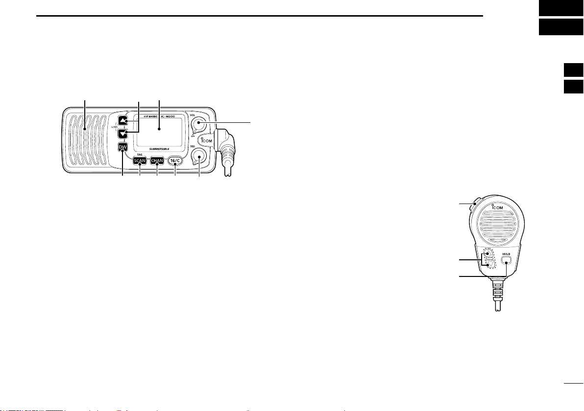
■ Front panel
Speaker
q CHANNEL UP/DOWN KEYS [▲]/[▼]•[U/I/C]
z Selects the operating channels, Set mode
settings and so on. (p. 4, 12)
z Selects one of 3 channel groups in sequence
when both keys are pushed. (p. 5)
w POWER/VOLUME CONTROL [VOL]
Rotate to turn the transceiver ON and OFF and
adjusts the audio volume level. (p. 6)
e SQUELCH CONTROL [SQL]
Rotate to set the squelch level. (p. 6)
L Rotate until the noise just disappears.
r CHANNEL 16/CALL CHANNEL KEY [16/C]
z Push to select Channel 16. (p. 4)
z Hold down for 1 second to select call channel.
(p. 4)
Function display (p. 3)
q
ertyu
w
t CHANNEL KEY [CHAN]
While pushing, push [16/C] to edit the channel
name. (p. 7)
y SCAN KEY [SCAN]•[TAG]
z Push to start or stop a scan. (p. 10)
z Hold down for 1 second to set or clear the
displayed channel as a TAG channel. (p. 10)
u DUALWATCH/TRI-WATCH KEY [DW]
Push to start or stop Dualwatch or Tri-watch.
(p. 11)
■ Microphone
q PTT SWITCH [PTT]
Hold down to transmit, release
to receive. (p. 6)
w CHANNEL UP/DOWN KEYS
[▲]/[▼]
Push either key to change the
operating channel, Set mode
settings and so on.
(p. 4, 12)
e TRANSMIT POWER KEY
[HI/LO]
z
Push to toggle between high and low power. (p. 6)
z While holding down, turn ON the transceiver to
toggle the Microphone Lock function ON or OFF.
(p. 8)
q
w
e
1
2
3
4
5
6
7
8
9
10
11
12
13
14
15
16
2
Page 6
PANEL DESCRIPTION
2
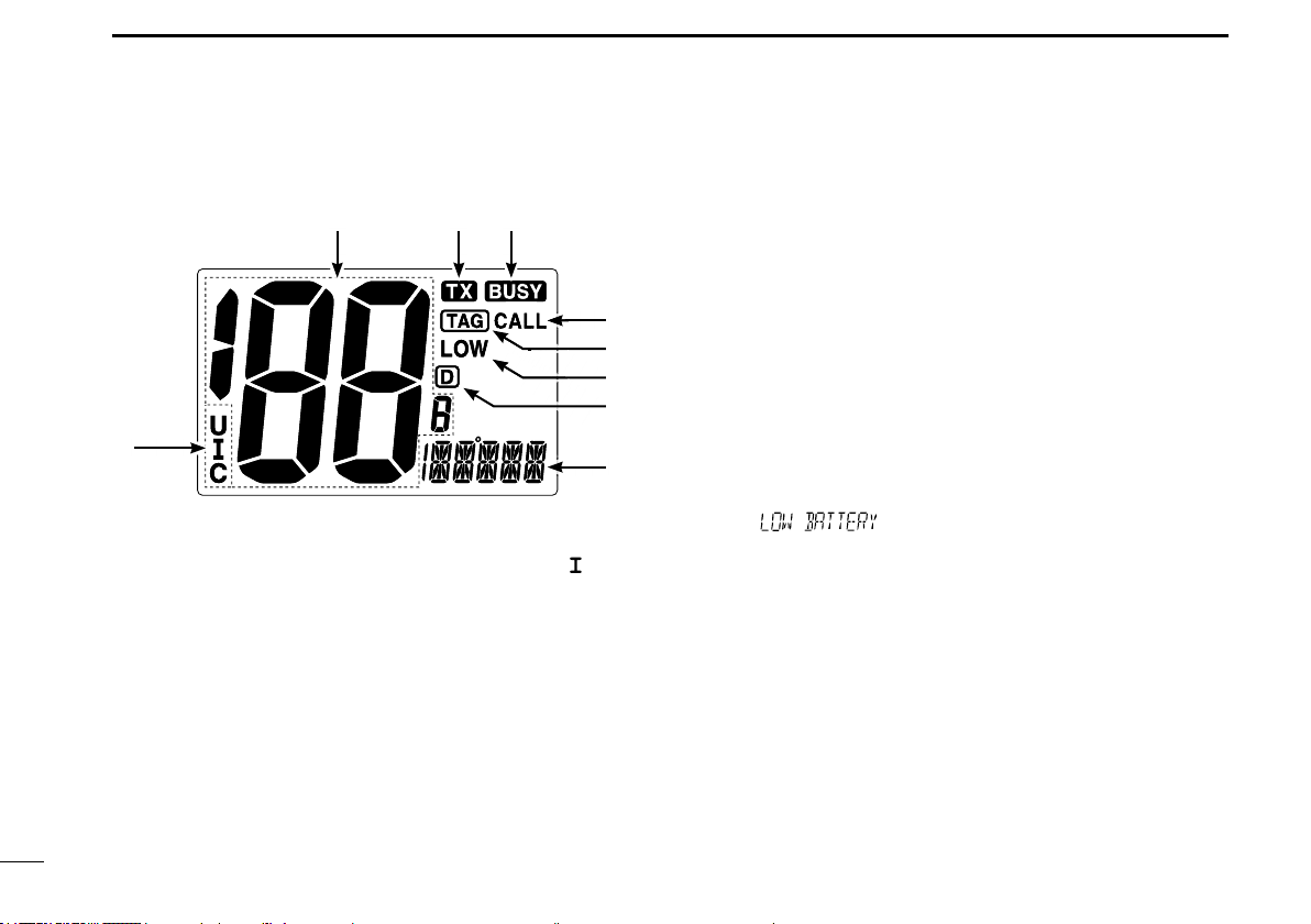
■ Function display
w e r
t
y
u
i
q
o
q CHANNEL GROUP ICON
Displayed when a U.S.A. “U,” International “ ,” or
Canadian “C” channel group is selected.
w CHANNEL NUMBER READOUT
Displays the selected channel number.
L See CHANNEL LIST (p. 18) for details.
e TRANSMIT ICON
Displayed while transmitting.
r BUSY ICON
Displayed when receiving a signal or when the
squelch is open.
t CALL CHANNEL ICON
Displayed when the Call channel is selected.
(p. 4)
y TAG CHANNEL ICON
Displayed when a TAG channel is selected.
(p. 10)
u LOW POWER ICON
Displayed when low power is selected.
i DUPLEX ICON
Displayed when a duplex channel is selected.
o CHANNEL NAME READOUT
Displays the selected channel name.
L “ ” scrolls when the battery voltage drops
to approximately 10.8 V DC or below.
3
3
Page 7
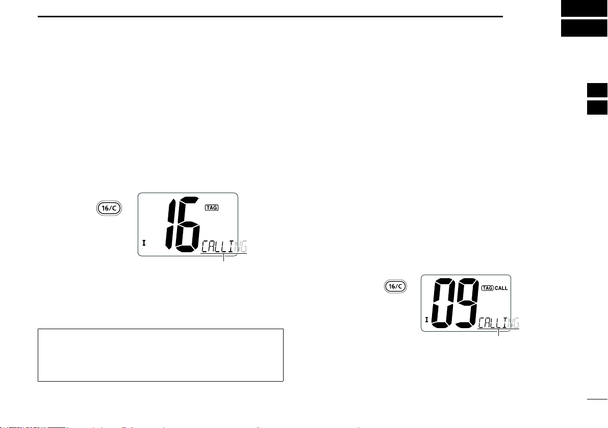
■ Selecting a channel
D Channel 16
Channel 16 is a Distress and safety channel. It is used
to make an initial contact with a station or to make
Emergency calls. Channel 16 is monitored during
Dualwatch and Tri-watch. While in standby, you must
monitor Channel 16.
z Push [16/C] to select Channel 16.
Push
Scrolls
L Push [CHAN] to return to the screen displayed before
you selected Channel 16.
L Push [▲] or [▼] to select an operating channel.
BASIC OPERATION
3
D Call channel
Each regular channel group has a separate Call
channel (Default: Channel 9*). A Call channel is a
channel that can be quickly recalled by simply pushing
a key. It is monitored during Tri-watch.
* Channel 16 or any other channel may be set as the Call
channel depending on the transceiver version. Ask your
dealer for details.
You can set your most frequently used channel as a
Call channel in each channel group. See “Setting a
Call channel” (p. 7) for details.
z Hold down [16/C] for 1 second to select the Call
channel of the selected channel group.
• “CALL” and Call channel number is displayed.
Hold down
for 1 second
1
1
2
2
3
3
4
4
5
5
6
6
7
7
8
8
9
9
10
10
11
11
12
12
13
13
14
14
15
15
TIP: When the FAV on MIC function (p. 13) is ON,
pushing [▲] or [▼] on the microphone sequentially
selects the TAG channels in the selected channel
group.
Scrolls
L Push [CHAN] to return to the screen displayed before
you selected Channel 16.
L Push [▲] or [▼] to select an operating channel.
4
4
16
16
Page 8
BASIC OPERATION
3
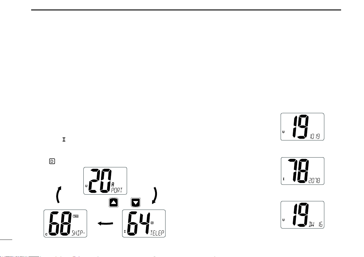
■ Selecting a channel (continued)
D USA,Canadian, and international
channels
The IC-M200 has 67 USA, 67 international, and 71
Canadian preset channels.
L These channel groups may be specied for your
operating area. Ask your delaer for details.
1. Push [Ù] and [Ú] on the transceiver at the same
time.
• USA, International, and Canadian channel groups are
selected in sequence.
L “U,” “
2. Push [Ù] or [Ú] to select your desired channel.
L“ ” is displayed when selecting a duplex channel.
,” or “C” is displayed to the left of the channel
number.
Push [U/I/C] (both
and )
D 4 digit channels
The 4 digit channels are displayed as shown below.
The channel number is displayed in the channel name
readout (at the bottom right) and the last 2 digits are
displayed in the channel number readout (center).
L The channel name cannot be displayed or entered.
Example: CH 1019
Example: CH 2078
Example: During Dualwatch or
Tri-watch
L The whole channel number
is not displayed.
5
Page 9

BASIC OPERATION
3
■ Receiving and transmitting
CAUTION: Transmitting without an antenna will
damage the transceiver.
1. Rotate [VOL] to turn ON the transceiver.
2. Set the audio and squelch levels.
z Rotate [SQL] fully counterclockwise.
z Rotate [VOL] to adjust the audio output level.
z Rotate [SQL] clockwise until the noise just
disappears.
3. Push [Ù] and [Ú] on the transceiver at the same
time to select the desired channel group. (p. 5)
4. Push [Ù] or [Ú] to select a channel. (p. 4)
L When receiving a signal, “ ” is displayed and
audio is output from the speaker.
5. Push [HI/LO] on the microphone to select the
output power if necessary.
L “LOW” is displayed when you select low power.
L Select low power for shorter distance and high power
for longer distance communications.
L For some channels, you can only select low power.
6. Hold down [PTT] to transmit, then speak at your
normal voice level.
• “ ” is displayed.
7. Release [PTT] to receive.
TIP: To maximize the readability of your transmitted
signal at a receiver station, pause a second after
pushing [PTT], and then hold the microphone 5 to
10 cm from your mouth and speak at your normal
voice level.
NOTE: About the Time-out Timer (TOT) function
The TOT function inhibits continuous transmission
beyond a preset time period from the transmission
starts. 10 seconds before transmission is cut off, a
beep sounds to indicate the transmission will be cut
off, and “TOT” appears in the channel name eld.
Release [PTT] to end your transmission and reset
the timer. You cannot transmit for 10 seconds after it
is cut off.
1
2
3
4
5
6
7
8
9
10
11
12
13
14
15
16
6
Page 10

BASIC OPERATION
3
■ Setting a Call channel ■ Entering a channel name
The Call channel is used to select Channel 9 (default).
However, you can set another channel as the Call
channel in each channel group.
1. Push [Ù] and [Ú] on the transceiver at the same
time to select the desired channel group. (p. 5)
2. Hold down [16/C] for 1 second to select the Call
channel of the selected channel group.
• “CALL” and Call channel number is displayed.
3. Hold down [16/C] again for
3 seconds (until a long beep
changes to 2 short beeps) to
enter the Call Channel Set
mode.
• Channel number blinks.
4. Push [Ù] or [Ú] to select the
desired channel.
5. Push [16/C] to set the
displayed channel as the Call
channel.
• 2 short beeps sound.
• The channel number stops
blinking and the setting is
saved.
L Push [CHAN] to cancel setting.
You can enter a channel name of up to 10 characters
each. A name with more than 6 characters is scrolled
after you select a channel.
L You cannot enter a channel name to 4 digit
channels.
L Capital letters, small letters (except f, j, k, p, s, v, x,
z), 0 to 9, some symbols (= * + – . /) and space can
be used.
NOTE: Cancel Dualwatch, Tri-watch or Scan in
advance.
1. Select the desired channel.
2. While holding down [CHAN],
push [16/C] to edit the channel
name.
• A cursor and the rst character
alternately blink.
3. Push [Ù] or [Ú] to select the desired character.
L Push [16/C] or [CHAN] to move the cursor forward or
backward.
4. Repeat step 3 to enter all characters.
5. Push [DW] to save the channel name.
• The cursor and the character stop blinking.
L Push [SCAN] to cancel the editing.
7
Page 11

BASIC OPERATION
3
■ The Microphone Lock function
The Microphone Lock function locks [▲], [▼], and
[HI/LO] on the supplied microphone. The function
prevents from accidentally changing channels or
functions.
z While holding down [HI/LO] on the microphone, turn
ON the transceiver to toggle the Microphone Lock
function ON or OFF.
■ Backlight brightness level
The display and keys can be backlit for better visibility
under low light conditions.
z While holding down [SCAN], push [▲] or [▼]
to adjust the brightness of the display and key
backlight.
L The brightness level is selectable in 3 levels, or OFF.
■ The AquaQuake function
You can use the AquaQuake function to clear water
away from the speaker grill. The function helps drain
water away from the speaker housing by emitting a
vibrating noise.
z While holding down [▲] and [▼] on the transceiver
at the same time, turn ON the transceiver.
• A low beep sounds while you hold both [▲] and [▼] to
drain water, regardless of [VOL] level setting.
L While the AquaQuake function is ON, key operations
are disabled.
L “
” scrolls.
1
2
3
4
5
6
7
8
9
10
11
12
13
14
15
16
8
Page 12

4
SCAN OPERATION
■ Scan types
You can nd ongoing calls by scanning the channels.
NOTE: Before starting a scan
• Set the channels you want to scan as TAG channels.
(p. 10) (Only TAG channels are scanned.)
• Select the scan type from "Normal (default)" or "Priority."
(p. 13)
NORMAL SCAN
CH 01 CH 02
CH 06
CH 05 CH 04
A normal scan sequentially searches through all TAG
channels. However, Channel 16 is not checked unless it
is set as a TAG channel.
CH 03
PRIORITY SCAN
CH 01
CH 06
CH 05 CH 04
A priority scan sequentially searches through all TAG
channels while also monitoring Channel 16.
When a signal is received on:
• Channel 16: The scan pauses until the signal on
Channel 16 disappears.
• A channel other than Channel 16:
The scan switches to Dualwatch, until the
signal disappears.
CH 16
CH 02
CH 03
9
9
Page 13

SCAN OPERATION
4
■ Setting TAG channels ■ Starting a scan
For more efcient scanning, you can set the desired
channel as a TAG channel or remove it from the
TAG channels. Channels that are not tagged will
be skipped during a scan. TAG channels can be
independently assigned to each channel group.
1. Push [Ù] and [Ú] on the transceiver at the same
time to select the desired channel group.
2. Select the desired channel to be set as a TAG
channel.
3. Hold down [SCAN] for 1 second to set the
displayed channel as a TAG channel.
• “ ” is displayed.
LTo clear the TAG channel setting, repeat step 3.
• “
” disappears.
TIP: Clearing (or setting) all TAG channels
While holding down [HI/LO] on the microphone, push
[SCAN] for 3 seconds (until a long beep changes
to 2 short beeps) to clear all TAG channels in the
selected channel group.
L Repeat the procedure to set all channels as TAG
channels.
NOTE: Select the scan type from "Normal (default)"
or "Priority." (p. 13)
1. Push [Ù] and [Ú] on the transceiver at the same
time to select the desired channel group.
2. Set the TAG channels as described to the left.
3. Confirm the squelch is closed to start a scan.
4. Push [SCAN] to start a Priority or Normal scan.
• “ ” blinks during a Priority scan, “ ” blinks
during a Normal scan.
L When a signal is detected, scan pauses until the
signal disappears or resumes after pausing
5 seconds, according to the Scan resume timer
setting. (p. 13) (Channel 16 is still monitored
during Priority scan.)
L Push [Ù] or [Ú] to check the scanning TAG channels,
to change the scanning direction or resume the scan
manually.
L A beep sounds and “
received on Channel 16 during Priority scan.
5. Push [SCAN] again to stop the scan.
” blinks when a signal is
1
2
3
4
5
6
7
8
9
10
11
12
13
14
15
16
10
10
Page 14

5
Dualwatch
DUALWATCH/TRI-WATCH
Dualwatch and Tri-watch are convenient to monitor
Channel 16 while you are operating on another
channel.
DUALWATCH/TRI-WATCH SIMULATION
Call channel
Monitors Channel 16
while receiving on
another channel.
(example: CH 88A)
When a signal is received on:
• Channel 16: Dualwatch/Tri-watch pauses on Channel
16 until the signal disappears.
• On the Call channel:
Tri-watch switches to Dualwatch until the
signal on the Call channel disappears.
Monitors Channel 16 and the
Call channel while receiving on
another channel.
(example: CH 88A)
Tri-watch
NOTE: Select Dualwatch or Tri-watch in the Set
mode. (p. 13)
1. Select the desired channel.
2. Push [DW] to start Dualwatch or Tri-watch.
• “DW” blinks during Dualwatch. “TW” blinks during Tri-
watch.
• A beep sounds when a signal is received on Channel 16.
3. Push [DUAL] (SCAN) again to cancel Dualwatch
or Tri-watch.
[Example]:Tri-watch on INT channel 25
1. Push
to start Tri-watch.
4. Tri-watch resumes after
the signal disappears.
2. Signal is received on the
Call channel.
3. A signal is received on
Channel 16 takes priority.
11
Page 15

SET MODE
6
■ Set mode
In the Set mode, you can change the settings of the
transceiver’s functions.
NOTE: Available functions may differ depending on
the dealer setting. Ask your dealer for details.
D Set mode operation
1. Turn OFF the transceiver.
2. While holding down [16/C], turn ON the
transceiver.
• Enters the Set mode.
• “SCAN” is displayed.
3. Push [16/C] several times until your desired item is
selected.
4. Push [▲] or [▼] to change the setting.
5. Turn OFF the transceiver, then ON again to exit
the Set mode.
D Set mode sequence
• Scan type • Scan resume timer
Starts with this item
• Dual/Tri-watch
Push
• FAV on MIC
Scrolls
• Key Beep
1
2
3
4
5
6
7
8
9
10
11
12
13
14
15
16
12
Page 16

BASIC OPERATION
Dualwatch (default) Tri-watch
6
■ Set mode items
Push [▲] or [▼] to change the setting
D Scan type
Select whether to start the Normal scan or Priority
scan after pushing [SCAN]. (p. 10)
Normal scan (default) Priority scan
D Scan resume timer
When the function is ON, the scan pauses for
5 seconds and resumes even if a signal has been
received on any channel other than Channel 16.
(p. 10)
Scan timer OFF (default) Scan timer ON
D Dual/Tri-watch
Select whether to start Dualwatch or Tri-watch after
pushing [DW]. (p. 11)
D Key Beep
Turn the key beep ON or OFF.
Beep ON (default) Beep OFF
D FAV on MIC
When the function is ON, [▲] or [▼] on the
microphone select only the TAG channels in the
selected channel group in sequence.
L “ ” scrolls in the lower right corner.
13
FAV on MIC ON (default) FAV on MIC OFF
Page 17

CONNECTIONS AND MAINTENANCE
7
■ Connections
q
q AF OUT LEADS
Blue: External Speaker (+)
Gray: External Speaker (–)
Connects to an external speaker.
Yellow: Data line
Green: Data line
Used only for maintenance purposes.
NOTE: AF out leads
The connectors are attached to keep the
leads together. Before connecting to a piece
of equipment, cut the leads to remove the
connectors, if desired.
w
e
w DC POWER CONNECTORS
Connects the supplied DC power cable to an
external 13.8 V DC power source.
CAUTION: After connecting the DC power
cable and external speaker lead, cover the
connector and leads with a vulcanizing tape, as
shown below, to prevent water seeping into the
connector.
Rubber vulcanizing
tape
e ANTENNA CONNECTOR
Connects to a marine VHF antenna.
CAUTION: Transmitting without an antenna may
damage the transceiver.
1
2
3
4
5
6
7
8
9
10
11
12
13
14
15
16
14
Page 18

CONNECTIONS AND MAINTENANCE
7
■ Supplied accessories
For the mounting bracket
Mounting bracket Knobs
Flat washers
(M5)
Microphone hanger
and screws (3×16 mm)
DC power cable
Screws (5×20 mm)
Spring washers
(M5)
■ Antenna
A key element in the performance of any
communication system is the antenna. Ask your
dealer about antennas and the best place to mount
them.
■ Replacing a fuse
If a fuse blows, or the transceiver stops functioning,
nd and repair the cause of the problem. Then replace
the damaged fuse with a new, adequately rated fuse.
Fuse Rating: 10 A
■ Cleaning
If the transceiver becomes dusty or dirty, wipe it clean
with a dry, soft cloth.
DO NOT use harsh solvents such as Benzine
or alcohol when cleaning, because they will
damage the transceiver surfaces.
15
Page 19

■ Mounting the transceiver
The universal mounting bracket supplied with your
transceiver enables dashboard or overhead mounting.
• Mount the transceiver rmly with the 2 supplied
screws (5×20 mm) on only a at hard board that the
screws won't penetrate.
• Mount the transceiver so that the face of the
transceiver is at 90° to your line of sight when
operating it.
CONNECTIONS AND MAINTENANCE
knob
7
7
CAUTION: KEEP the transceiver and microphone
at least 1 meter away from your vessel’s magnetic
navigation compass.
NOTE: Adjust the angle to make the function display
easy to read.
screw
5×20 mm)
(
spring washer
at washer
16
Page 20

8
TROUBLESHOOTING
PROBLEM POSSIBLE CAUSE SOLUTION REF.
Power does not come
on when turning ON the
transceiver.
No sound is heard from the
speaker.
Cannot transmit or output
power is low.
Scan does not start. “TAG” channels are not set. Set the channels you want to scan
No beeps. Key beeps are OFF. Turn ON the key beep in the Set
Power cable is improperly
connected.
Volume level is too low. Rotate [VOL] to a suitable listening
Speaker has been exposed to
water.
Squelch level is too high. Set squelch to the threshold point. p. 6
Channels that are only for receive
or low power are selected.
Low power is selected. Push [HI/LO] on the microphone to
Reconnect the DC power cable
correctly.
level.
Drain water from the speaker. p. 8
Select other channels. p. 18
select high power.
as “TAG” channels.
mode.
p. 14
p. 6
p. 6
p. 10
p. 13
17
Page 21

CHANNEL LIST
9
Channel number Frequency (MHz)
USA
01A 156.050 156.050
03A 156.150 156.150
05A 05A 156.250 156.250
06 06 156.300 156.30006
07A 07A 156.350 156.350
08 08 156.400 156.40008
09 09 156.450 156.45009
10 10 156.500 156.50010
11 11 156.550 156.55011
12 12 156.600 156.60012
13*
14 14
15*
16 16
17*
18A 18A
19A 19A 156.950 156.950
20 20*
20A 157.000 157.000
1
*
Low power only. *2 Momentary high power.
CAN
INT
2
13
14
2
15*
16
1
17
18
19
Transmit Receive
01
156.050 160.65001
02 156.100 160.70002
03 156.150 160.75003
156.200 160.80004
04A 156.200 156.200
156.250 160.85005
156.350 160.95007
13*1156.650 156.650
156.700 156.700
1
15*1156.750 156.750
156.800 156.800
17*1156.850 156.850
156.900 161.500
156.900 156.900
156.950 161.550
1
157.000 161.60020
Channel number Frequency (MHz)
USA
21A 21A 157.050 157.050
22A 22A 157.100 157.100
23A 157.150 157.150
24 24 157.200 161.80024
25 25 157.250 161.85025
26 26 157.300 161.90026
27 27 157.350 161.95027
28 28 157.400 162.00028
61A 61A 156.075 156.075
63A 156.175 156.175
64A 64A 156.225 156.225
65A 65A 156.275 156.27565A
66A 66A*
67*
Channel number Frequency (MHz)
CAN
INT
2
Transmit Receive
21 157.050 161.65021
21b Rx only 161.650
157.100 161.70022
23 157.150 161.75023
25b Rx only 161.850
28b Rx only 162.000
60 156.025 160.62560
156.075 160.67561
156.125 160.72562
62A 156.125 156.125
156.175 160.77563
64 156.225 160.82564
156.275 160.87565
156.325 160.92566
1
156.325 156.32566A
67 156.375 156.37567
CAN
INT
USA
68
69 69 156.475 156.47569
71 71 156.575 156.57571
72 72 156.625 156.62572
73 73 156.675 156.67573
74 74 156.725 156.72574
1
75*
1
76*
1
77*
78A 78A 156.925 156.925
79A 79A 156.975 156.975
80A 80A 157.025 157.025
81A 81A 157.075 157.075
82A 82A 157.125 157.125
83A 83A 157.175 157.175
84 84 157.225 161.82584
84A 157.225 157.225
85 85 157.275 161.87585
85A 157.275 157.275
86 86 157.325 161.92586
86A 157.325 157.325
Transmit Receive
68 156.425 156.42568
1
75*1156.775 156.77575*
1
76*1156.825 156.82576*
77*1156.875 156.87577
156.925 161.52578
156.975 161.57579
157.025 161.62580
157.075 161.67581
157.125 161.72582
83 157.175 161.77583
83b Rx only 161.775
Channel number Frequency (MHz)
USA
87 87 157.375 161.97587
87A 157.375 157.375
88 88 157.425 162.02588
88A 157.425 157.425
Channel number
USA/INT/CAN
INT
1020
1078
1079
2019
2020
2078
2079
CAN
Transmit Receive
Frequency (MHz)
Transmit Receive
156.9501019
157.000 157.000
156.925 156.925
156.975 156.975
161.550 161.550
161.600 161.600
161.525 161.525
161.575 161.575
156.950
1
2
3
4
5
6
7
8
9
10
11
12
13
14
15
16
NOTE: Simplex channels, 3, 21, 23, 61, 64, 81, 82 and 83 CANNOT
be lawfully used by the general public in U.S.A. waters.
18
Page 22

10
SPECIFICATIONS AND OPTIONS
■ Specications
19
19
General
• Frequency coverage:
Transmit 156.025~162.000 MHz
Receive 156.025~162.025 MHz
• Type of emission : FM (16K0G3E)
• Antenna impedance : 50 Ω nominal
• Operating temperature range:
–20°C to +60°C
• Power supply voltage (negative ground):
13.8 V DC
• Current drain (at 13.8 V):
TX (at 25 W) 5.5 A maximum
Maximum audio 1.5 A maximum
• Dimensions: 153(W) × 67(H) × 133(D) mm
• Weight (approximately): 790 g
Transmitter
• Rated output power: 25 W (High) and 1 W (Low)
• Modulation: Variable reactance frequency
modulation
• Maximum frequency deviation:
±5.0 kHz
• Frequency tolerance: ±5.0 ppm
• Spurious emissions: Less than –70 dBc (High)
Less than –56 dBc (Low)
• Adjacent channel power: More than 70 dB
• Audio harmonic distortion (at 60% deviation):
Less than 10%
• Residual modulation: More than 40 dB
Receiver
• Intermediate frequencies: 1st 21.7 MHz, 2nd 450 kHz
• Sensitivity (12 dB SINAD)
• Squelch sensitivity: Less than –117 dBm
• Audio power output (at 10% distortion into 4 Ω):
4.5 W typical
• Adjacent channel selectivity: More than 70 dB
• Spurious response: More than 70 dB
• Intermodulation: More than 70 dB
• Hum and noise: More than 40 dB
: –121 dBm typical
■ Options
• MB-69 flush mount kit
• MB-92 dust cover
Approved Icom optional equipment is designed for optimal
performance when used with an Icom transceiver.
Icom is not responsible for the destruction or damage to the Icom
transceiver, if the malfunction is because of:
• Force majeure, including, but not limited to, res, earthquakes,
storms, oods, lightning, other natural disasters, disturbances,
riots, war, or radioactive contamination.
• The use of Icom transceivers with any equipment that is not
manufactured or approved by Icom.
Page 23

INDEX
4 digit channels.................................... 5
Accessories ....................................... 15
AF out lead ........................................ 14
Antenna ............................................. 15
Antenna connector ............................ 14
AquaQuake function ............................ 8
Audio output level ................................ 6
Backlight .............................................. 8
Call channel ......................................... 4
Setting ............................................. 7
Channel
Channel 16 ...................................... 4
Channel group ................................ 5
Channel list ................................... 18
Channel name, Entering ................. 7
Channel, Selecting .......................... 4
Cleaning ......................................... i, 15
Connections....................................... 14
DC power connector .......................... 14
Display ................................................. 3
Distress call .......................................... i
Dualwatch .................................... 11, 13
Emergency ........................................... i
Front panel .......................................... 2
Function display................................... 3
Fuse, Replacing................................. 15
High power .......................................... 6
Lock function ....................................... 8
Low power ........................................... 6
Microphone .......................................... 2
Microphone Lock function.................... 8
Mounting ............................................ 16
Options .............................................. 19
Output power ....................................... 6
Receiving ............................................. 6
Scan
Normal scan .................................... 9
Priority scan .................................... 9
Starting a scan .............................. 10
Scan type ........................................ 9
Scan resume timer ........................ 13
Set mode ........................................... 12
Items ............................................. 13
Dual/Tri-watch ..........................13
FAV on MIC .............................. 13
Key Beep .................................. 13
Scan resume timer ................... 13
Scan type ................................. 13
Operation ...................................... 12
Sequence ...................................... 12
Specications .................................... 19
Squelch................................................ 6
Supplied accessories......................... 15
TAG channel
Clearing ......................................... 10
Setting ........................................... 10
Time-out Timer .................................... 6
TOT ..................................................... 6
Transmitting ......................................... 6
Tri-watch ...................................... 11, 13
Troubleshooting ................................. 17
1
2
3
4
5
6
7
8
10
11
12
13
14
15
16
Icom, Icom Inc. and Icom logo are registered trademarks of Icom Incorporated (Japan) in Japan, the United States,
the United Kingdom, Germany, France, Spain, Russia, Australia, New Zealand, and/or other countries.
20
20
Page 24

A-7299H-1EX-q
Printed in Japan
© 2016 Icom Inc.
1-1-32 Kamiminami, Hirano-ku, Osaka 547-0003, Japan
 Loading...