

Page 1
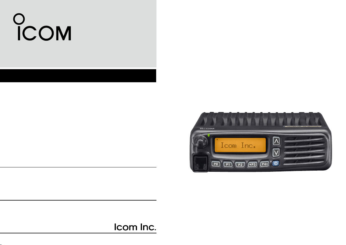
INSTRUCTION MANUAL
VHF MOBILE TRANSCEIVER
iF5061/D
iF5063
UHF MOBILE TRANSCEIVER
iF6061/D
iF6063
Page 2

IMPORTANT EXPLICIT DEFENITIONS
READ ALL INSTRUCTIONS carefully and com-
pletely before using the transceiver.
SAVE THIS INSTRUCTION MANUAL — This
instruction manual contains important operating instructions
for the IC-F5061/D, IC-F5063 VHF MOBILE TRANSCEIV-
ERS, IC-F6061/D, IC-F6063 UHF MOBILE TRANSCEIVERS.
See the operating guide for details of BIIS, MDC, LTR®
and Digital system operations. Ask your dealer for details.
Icom, Icom Inc. and the logo are registered trademarks of Icom Incorporated (Japan) in the United States, the United Kingdom, Germany, France,
Spain, Russia and/or other countries.
LTR is a registered trademark of the E.F.Johnson Company.
All other products or brands are registered trademarks or trademarks of their
respective holders.
i
WORD DEFINITION
RWARNING
CAUTION
NOTE
Personal injury, fire hazard or electric
shock may occur.
Equipment damage may occur.
If disregarded, inconvenience only. No risk
of personal injury, fire or electric shock.
Page 3

PRECAUTIONS
RWARNING! NEVER connect the transceiver to an AC
outlet. This may pose a fire hazard or result in an electric shock.
RWARNING! NEVER connect the transceiver to a
power source of more than 16 V DC such as a 24 V battery.
This connection will ruin the transceiver.
RWARNING! NEVER cut the DC power cable be-
tween the DC plug and fuse holder. If an incorrect connec
tion is made after cutting, the transceiver might be damaged.
RWARNING! NEVER place the transceiver where
normal operation of the vehicle may be hindered or where it
could cause bodily injury.
CAUTION! NEVER allow children to touch the trans-
ceiver.
CAUTION! NEVER expose the transceiver to rain,
snow or any liquids.
USE the specified microphone only. Other microphones have
different pin assignments and may damage the transceiver.
DO NOT use or place the transceiver in areas with tem-
peratures below –30°C (–22°F) or above +60°C (+140°F), or
in areas subject to direct sunlight, such as the dashboard.
DO NOT operate the transceiver without running the ve-
hicle’s engine. The vehicle’s battery will quickly run out when
the transceiver transmits while the vehicle’s engine is OFF.
DO NOT place the transceiver in excessively dusty envi-
ronments.
DO NOT place the transceiver against walls. Otherwise
heat dissipation will be obstructed.
-
DO NOT use chemical agents such as benzine or alcohol
when cleaning, as they damage the transceiver surfaces.
BE CAREFUL! The transceiver will become hot when
operating continuously for long periods.
For U.S.A. only
CAUTION! Changes or modifications to this transceiver, not
expressly approved by Icom Inc., could void your authority to
operate this transceiver under FCC regulations.
Icom optional equipment is designed for optimal perform
ance when used with this transceiver. We are not respon
sible for the transceiver being damaged or any accident
caused when using non-Icom optional equipment.
-
-
ii
Page 4

VOICE CODING TECHNOLOGY
FCC INFORMATION
The AMBE+2™ voice coding Technology embodied in this
product is protected by intellectual property rights including
patent rights, copyrights and trade secrets of Digital Voice
Systems, Inc. This voice coding Technology is licensed
sole ly for use within this Co mmunications Eq uipment.
The user of this Technology is explicitly prohibited from
attempting to extract, remove, decompile, reverse engineer,
or disassemble the Object Code, or in any other way convert
the Object Code into a human-readable form. U.S. Patent
Nos.
#5, 8 7 0 , 405, #5 , 8 26,2 2 2 , #5,75 4 , 9 7 4, #5 , 7 0 1,39 0 ,
#5, 7 1 5 , 365, #5 , 6 49,0 5 0 , #5,63 0 , 0 1 1, #5 , 5 8 1,65 6 ,
#5,517,511 , # 5,4 91,772, #5,247,57 9, #5,226,0 84 and
#5,195,166.
• FOR CLASS B UNINTENTIONAL RADIATORS:
This equipment has been tested and found to comply with
the limits for a Class B digital device, pursuant to part 15 of
the FCC Rules. These limits are designed to provide reason
able protection against harmful interference in a residential
installation. This equipment generates, uses and can radiate
radio frequency energy and, if not installed and used in ac
cordance with the instructions, may cause harmful interfer
ence to radio communications. However, there is no guaran
tee that interference will not occur in a particular installation.
If this equipment does cause harmful interference to radio or
television reception, which can be determined by turning the
equipment off and on, the user is encouraged to try to cor
rect the interference by one or more of the following meas
ures:
• Reorient or relocate the receiving antenna.
• Increase the separation between the equipment and re
ceiver.
• Connect the equipment into an outlet on a circuit differ
ent from that to which the receiver is connected.
• Consult the dealer or an experienced radio/TV techni
cian for help.
-
-
-
-
-
-
-
-
-
iii
Page 5
TABLE OF CONTENTS
IMPORTANT .......................................................................... i
EXPLICIT DEFINITIONS ....................................................... i
PRECAUTIONS .................................................................... ii
VOICE CODING TECHNOLOGY ........................................ iii
FCC INFORMATION ........................................................... iii
TABLE OF CONTENTS ....................................................... iv
1
PANEL DESCRIPTION ................................................1−7
■ Front panel ................................................................... 1
■ Function display ...........................................................2
■ Programmable function keys ........................................3
2
BASIC OPERATION ..................................................8−13
■ Turning power ON ........................................................8
■ Channel selection .........................................................8
■ Call procedure ..............................................................9
■ Receiving and transmitting ...........................................9
■ User set mode ............................................................12
■ Scrambler function .....................................................13
■ Emergency transmission ............................................13
■ Stun function ..............................................................13
■ Priority A channel selection ........................................13
3
CONNECTION AND MAINTENANCE ....................14−16
■ Rear panel connection ...............................................14
■ Supplied Accessories .................................................15
■ Mounting the transceiver ............................................15
■ Antenna ......................................................................16
■ Fuse replacement ......................................................16
■ Cleaning ..................................................................... 16
■ Options .......................................................................16
4
SAFETY TRAINING INFORMATION .............................17
1
2
3
4
5
6
7
8
9
10
11
12
13
14
15
16
iv
Page 6
I c o m I n c .
q e
y
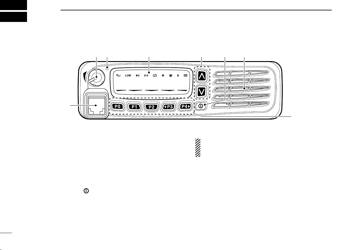
SpeakerFunction display (p. 2)
w r
t
1
PANEL DESCRIPTION
■ Front panel
q AF VOLUME CONTROL KNOB [VOL]
Rotate the knob to adjust the desired audio output level.
• Minimum audio level is pre-programmed.
w LED INDICATOR
➥ Lights red while transmitting a signal.
➥ Lights green while receiving a signal.
e UP/DOWN KEYS [CH Up]/[CH Down]
Push to select an operating channel, etc.
* The desired function can be assigned by your dealer. (p. 3)
r POWER SWITCH [ ]
Push and hold for 1 sec. to turn the power ON and OFF.
• Automatic scan start, Password prompt and Set mode access
are available at power ON.
t DEALER-PROGRAMMABLE KEYS
Desired functions can be programmed independently by
your dealer. (p. 3)
1
y MICROPHONE CONNECTOR
Connect the supplied or optional microphone.
NEVER connect non-specified microphones. The pin
assignments may be different and the transceiver may
be damaged.
D MICROPHONE
The supplied microphone has a PTT switch and a hanger
hook.
• The following functions are available when the microphone is on or
off hook (depending on the setting):
- Automatic scan starts when it is on hook.
- Scan is cancelled when it is off hook.
- Scan is paused when it is off hook.
- Automatic priority channel selection is available when it is off
hook.
- Sets to ‘Inaudible’ condition (mute condition) when it is on hook.
- Sets to ‘Audible’ condition (unmute condition) when it is off hook.
Page 7
I c o m I n c.
!1
q w e r t y u i o
!0
Weak Receive Signal level Strong
PANEL DESCRIPTION
1
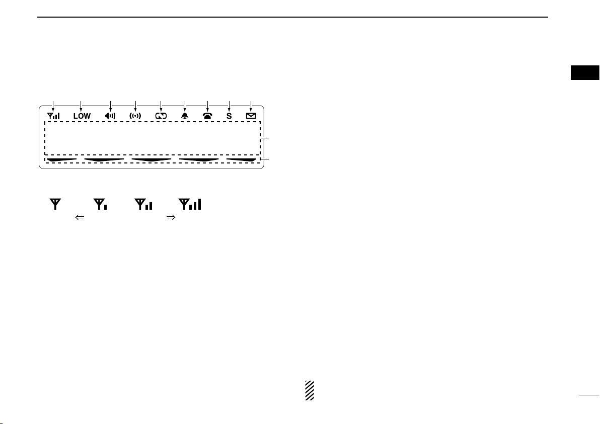
■ Function display
q SIGNAL STRENGTH INDICATOR
Indicates relative signal strength level as below.
w LOW POWER INDICATOR
Appears when low output power is selected.
e AUDIBLE INDICATOR
➥ Appears when the channel is in the ‘audible’ (unmute)
condition.
➥ Appears when the specified 2/5-tone/BIIS*1/MDC*2
code is received.
r COMPANDER INDICATOR
Appears when the compander function is activated.
t SCRAMBLER INDICATOR
Appears when the voice scrambler function is activated.
y BELL INDICATOR
Appears/blinks when the specific 2/5-tone/BIIS*
code is received, according to the pre-programming.
1
/MDC*2
u CALL CODE MEMORY INDICATOR
➥ Appears when the call code memory is selected.
➥ Appears when a phone call is received.*
i SCROLL INDICATOR
Appears when the SDM, includes more than 12 charac
ters, is selected during the received message selection
mode*1.
o SDM INDICATOR
Appears when an SDM is received, or a transmit SDM is
selected.*
!0 ALPHANUMERIC DISPLAY
➥ Displays an operating channel number, channel name,
➥ The indication mode can be selected from 1 line or 2
• In this instruction manual, the LCD illustration is described
!1 ACTIVATED KEY INDICATOR
Appears above the key assigned as [Scan A Start/Stop],
[Scan B Start/Stop], [Scan Add/Del(Tag)], [Lock], [Talk
Around], [Surveillance] and [BIIS button]*
that key is activated.
*1 BIIS operation only *2 MDC operation only
*3 LTR® operation only
See the operating guide for details of BIIS, MDC, LTR®
and Digital system operations. Ask your dealer for details.
1
Set mode contents, DTMF code, etc.
lines. Ask your dealer for details.
using the 2 lines indication mode.
3
1
keys during
1
2
3
4
-
5
6
7
8
9
10
11
12
13
14
15
16
2
Page 8

PANEL DESCRIPTION
1
■ Programmable function keys
The following functions can be assigned to [UP], [DOWN],
[P0], [P1], [P2], [P3] and [P4] programmable function keys.
Consult your Icom dealer or system operator for details con
cerning your transceivers programming.
If the programmable function names are bracketed in the fol
lowing explanations, the specific key is used to activate the
function depends on the programming.
CH UP AND DOWN KEYS
➥ Push to select an operating channel.
➥ Push to select a transmit code channel after pushing [TX
Code CH Select].
➥ Push to select a DTMF channel after pushing [DTMF Au-
todial].
➥ Push to select a scan group after pushing and holding
[Scan A Start/Stop]/[Scan B Start/Stop] for 1 sec.
ZONE KEY
Push this key, then select the desired zone using [CH Up]/
[CH Down].
What is “zone”?— Selected channels are assigned to a
zone according to how they are to be used in a group.
For example, ‘Staff A’ and ‘Staff B’ are assigned into a
“Business” zone, and ‘John’ and ‘Cindy’ are assigned into
a “Private” zone.
ZONE UP AND DOWN KEYS
Push to select an operating zone.
-
SCAN A KEY
Push to start and cancel scanning operation.
➥
-
• When Power ON Scan function is activated, push to pause the
scanning operation. And the paused scan resumes after the
specified time period has passed.
ush and hold this key for 1 sec. to indicate the scan list,
➥ P
then push [CH Up] or [CH Down] to select the desired list.
SCAN B KEY
Push to start and cancel scanning operation.
➥
The scan restarts after the specified time period has
passed when the scan (started with this key) is cancelled
by except for this key operation.
Push and hold this key for 1 sec. to indicate the scan list,
➥
then push [CH Up] or [CH Down] to select the desired list.
3
Page 9

PANEL DESCRIPTION
1
1
SCAN ADD/DEL (TAG) KEY
➥ Push to add or delete the selected channel to/from the
scan group.
1.
Push to indicate the scan group, then push [CH Up] or [CH Down]
to select the desired group.
2. Push to add or delete the channel to/from the selected scan
group.
3. Push and hold for 1 sec. to exit the scan group selection mode.
➥ Push this key while scan is paused (a signal is detected)
on a channel (except for priority channel,) the channel is
cleared from the scan group.
Depending on the setting, the cleared channel is added
to the scan group again after the scan is cancelled.
PRIO A/B KEYS
➥ Push to select Priority A or Priority B channel.
➥ Push and hold [Prio A (Rewrite)] or [Prio B (Rewrite)] for
1 sec. to rewrite the operating channel as the Priority A or
Priority B channel.
MR-CH 1/2/3/4 KEYS
Push to select the memory channel 1 to 4 directly.
MONI (AUDI) KEY
➥ Push to mute and release the CTCSS (DTCS) or 2-tone
squelch mute. Open any squelch/deactivate any mute
while pushing and holding this key.
(LMR operation only)
➥ Activates one of (or two of) the following functions on
each channel independently:
• Push and hold to un-mute the channel (audio is emitted; ‘Audible’ condition).
• Push to mute the channel (sets to ‘Inaudible’ only).
• Push to un-mute the channel (sets to ‘Audible’ only).
• Push after the communication is finished to send a ‘reset code’.
(5-tone/BIIS operation only)
NOTE: The un-mute condition (‘Audible’ condition) may
(PMR operation only)
automatically return to the mute condition (‘Inaudible’
condition) after a specified period depending on pro
gramming.
PUBLIC ADDRESS KEY
Push to activate the Public Address (PA) function for voice
amplification. When the PA function is activated, the audio
output can be controlled from the transceiver separately with
[CH Up]/[CH Down].
• This function is available when the external unit, such as a audio
amplifier, speaker, etc. is additionally connected.
• Push this key, then speak into the microphone while pushing and
holding [PTT].
-
4
Page 10

PANEL DESCRIPTION
1
RX SPEAKER KEY
Push to turn the RX speaker function ON or OFF.
When the RX speaker function is turned ON, the received
audio can be heard via the external speaker.
• This function is available when the external speaker is additionally
connected.
• This function is useful when you are out of the vehicle.
• The audio output level is linked to the transceiver’s volume control.
LIGHT KEY
Push to turn the transceiver’s backlight ON for about 5 sec.
when the backlight function is turned OFF in user set mode.
LOCK KEY
Push and hold to electronically lock all programmable keys
except the following:
[M oni (Audi) ], [ Lig ht], [Lo ck] , [Ca ll] (inc l. Ca ll A an d Ca ll B),
[Emergency], [Surveillance], [Lone Worker] and [OPT 1/2/3].
LONE WORKER KEY
Push to turn the Lone Worker function ON or OFF.
• If the Lone Worker function is activated, the Emergency function is
automatically turned ON after the specified time period has passed
with no operation is performed.
HIGH/LOW KEY
Push to select the transmit output power temporarily or per
manently, depending on the pre-setting.
• Ask your dealer for the output power level for each selection.
TONE/RAN CH SELECT KEY
➥ While in analog mode operation, push to enter the con-
tinuous tone channel selection mode. Then select the
desired tone frequency/code setting with [CH Up] or [CH
Down]. After the selection, push this key again to set.
➥ While in digital mode operation, push to enter the RAN
channel selection mode. Then select the desired RAN set
ting with [CH Up] or [CH Down]. After the selection, push
this key again to set.
➥ While in mixed (digital and analog) mode operation, push
to enter the continuous tone channel selection mode.
Then select the desired tone frequency/code setting with
[CH Up] or [CH Down]. After the selection, push this key
to set. After that, the RAN channel selection screen ap
pears. Select the desired RAN setting with [CH Up] or [CH
Down]. After the selection, push this key again to set.
C.TONE CH ENT KEY
Push to select the continuous tone channel using [CH Up]/
[CH Down] to change the tone frequency/code setting after
pushing this key. The selected channel remains set as the
continuous tone channel until another channel is designated
as such. (Analog or mixed mode operation only)
TALK AROUND KEY
Push to turn the talk around function ON and OFF.
-
• The talk around function equalizes the transmit frequency to the
receive frequency for transceiver-to-transceiver communication.
-
-
5
Page 11

PANEL DESCRIPTION
1
WIDE/NARROW KEY
Push to toggle the IF bandwidth between wide and narrow.
(Analog or mixed mode operation only)
• The wide passband width can be selected from 25.0 or 20.0 kHz
using the CS-F5060 cloning software. (PMR operation only) Ask
your dealer for details.
DTMF AUTODIAL KEY
Push to enter the DTMF channel selection mode. Then select
the desired DTMF channel using [CH Up]/[CH Down].
After selecting the DTMF channel, push again to transmit
the selected DTMF code.
RE-DIAL KEY
Push to transmit the last-transmitted DTMF code.
• TX memories are cleared after turning the transceiver OFF.
CALL KEYS
Push to transmit a 2/5-tone/BIIS ID code.
• Call transmission is nec essary before ca lling another station
depending on your signalling system.
• [Call A] and/o r [Cal l B ] may be avai lable when yo ur syste m
employs selective ‘Individual/Group’ calls. Ask your dealer which
call is assigned to each key.
EMERGENCY KEY
Push and hold to transmit the emergency call.
• The emergency call transmits with beeps; the display does not
change.
• The transceiver can transmit the emergency call silently or with the
display changes depending on the pre-setting. Ask your dealer for
details.
• If you want to cancel the emergency call, push and hold the key
again before transmitting the call.
• The emergency call is transmitted one time only or repeatedly until
receiving a control code, depending on the pre-setting.
SURVEILLANCE KEY
Push to turn the surveillance function ON or OFF.
When this function is turned ON, the beep is not emitted and
the LCD backlight and the LED indicator do not light when a
signal is received or a key is pushed.
TX CODE ENTER KEY (PMR operation only)
Push t o enter the I D code ed it mode d ire ctly, for bot h
5-tone and MSK. Then set the desired digit using [CH Up]/
[CH Down]. (p. 11)
TX CODE CHANNEL SELECT KEY
➥ P ush t o ente r the ID code c hann el sel ecti on mod e
directly. Then set the desired channel using [CH Up]/
[CH Down]. (p. 10)
➥ During ID code channel selection mode, push for 1 sec.
to enter the ID code edit mode for 5-tone and MSK. Then
set the desired digit using [CH Up]/[CH Down]. (p. 11)
1
6
Page 12

PANEL DESCRIPTION
1
TX CODE CHANNEL UP/DOWN KEYS
Push to select a TX code channel directly.
SCRAMBLER/ENCRYPTION KEY
➥ While in analog mode operation, push to toggle the voice
scrambler function ON and OFF.
➥ Whil e in di git al mode operation , pus h to to ggl e the
encryption transmission function ON and OFF.
COMPANDER KEY
Push to toggle the compander function ON and OFF.
The compander function reduces noise components from
the transmitted audio to provide clear communication.
ID-MR SELECT KEY (PMR operation only)
➥ Recalls detected ID codes.
• P u s h this ke y, then se l e ct the ID code u s i n g [CH Up]/
[CH Down].
• Up to 5 ID’s are memorized.
➥ Push and hold for 1 sec. to erase the selected ID’s.
HOOK SCAN KEY
When the on hook scan function is activated, push this key
to disables on hook scan function (stop scanning) temporar
ily. Push this key again to re-start scanning.
USER SET MODE KEY
➥ Push and hold for 1 sec. to enter user set mode.
• During user set mode, push this key to select an item, and
change the value or condition using [CH Up]/[CH Down].
➥
Push and hold this key for 1 sec. again to exit user set mode.
User set mode is also available via the ‘Power ON function.’
Refer to p. 12 also.
10Key ENT KEY
Push to enable the connected microphone's 10-keypad
operation.
• The desired memory channel, TX code channel (5-tone), ID list
number (digital), TX status (MSK/Digital) or Short Data Message
(digital) can be selected. (Depends on the pre-programming.)
OPT 1/2/3 KEYS
Push to control the output signal level from the optional unit
connector.
-
7
Page 13
BASIC OPERATION
KEY
NUMBER
0
5
4
9
3
8
2
7
1
6
2
■ Turning power ON
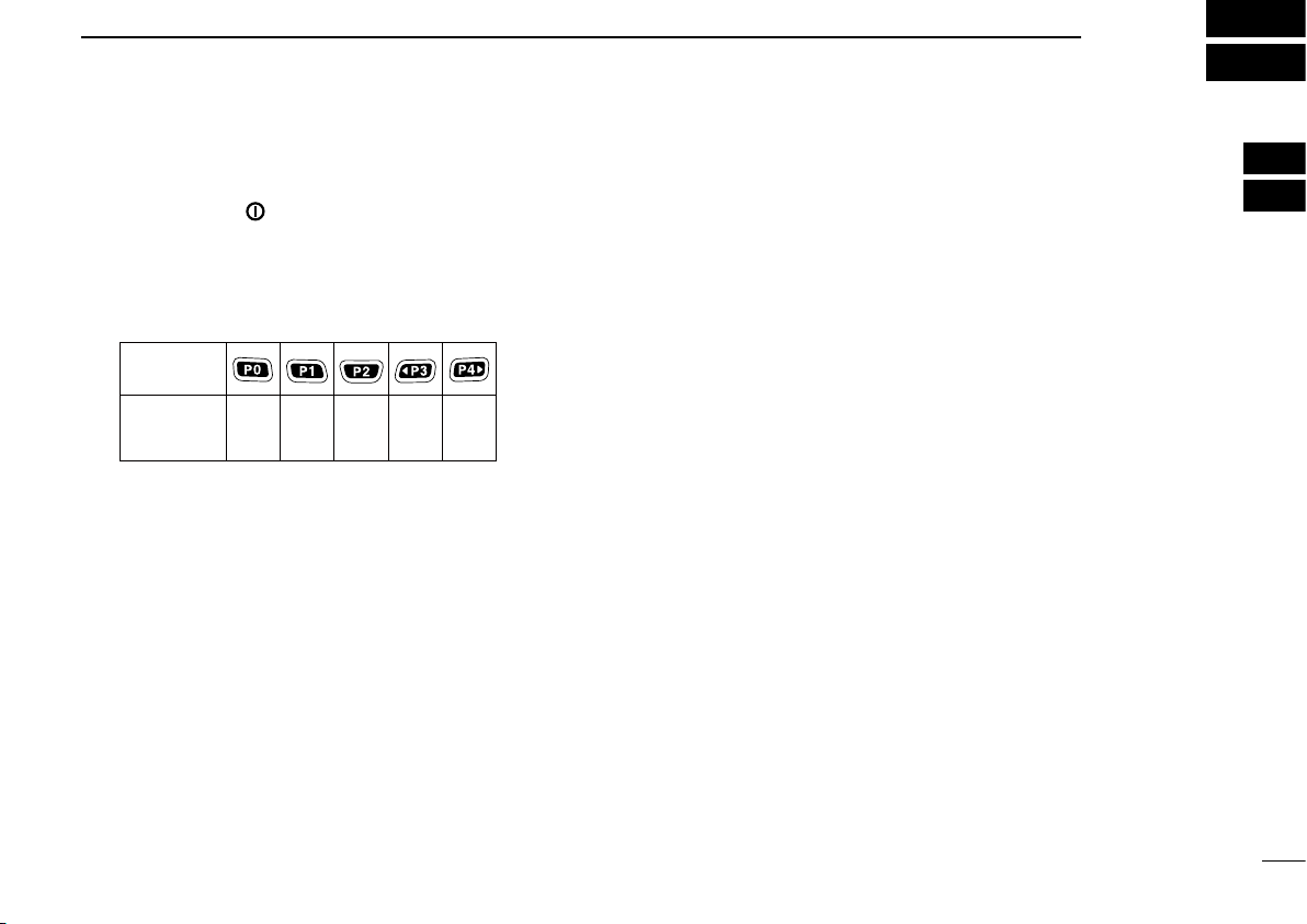
q Push and hold [ ] for 1 sec. to turn the power ON.
w If the transceiver is programmed for a start up password,
input the digit codes as directed by your dealer.
• The keys as below can be used for password input:
The transceiver detects numbers in the same block as identical.
Therefore “01234” and “56789” are the same.
e When the “PASSWORD” indication does not clear after
inputting 6 digits, the input code number may be incorrect.
Turn the power off and start over in this case.
■ Channel selection
Several types of channel selections are available. Methods
may differ according to your system set up.
NON-ZONE TYPE:
To select the desired operating channel:
• Push [CH Up] or [CH Down].
• Push one of [MR-CH 1] to [MR-CH 4].
ZONE TYPE:
To select the desired zone:
• Push [Zone], then push [CH Up] or [CH Down].
• Push [Zone Up] or [Zone Down].
D Voting operation
The transceiver automatically starts scanning when a zone,
specified for the voting operation, is selected.
The voting scan detects the S-meter of the repeater and
automatically selects the strongest station.
AUTOMATIC SCAN TYPE:
Channel setting is not necessary for this type. When turning
power ON, the transceiver automatically star ts scanning.
Scanning stops when receiving a call.
1
2
3
4
5
6
7
8
9
10
11
12
13
14
15
16
8
Page 14
BASIC OPERATION
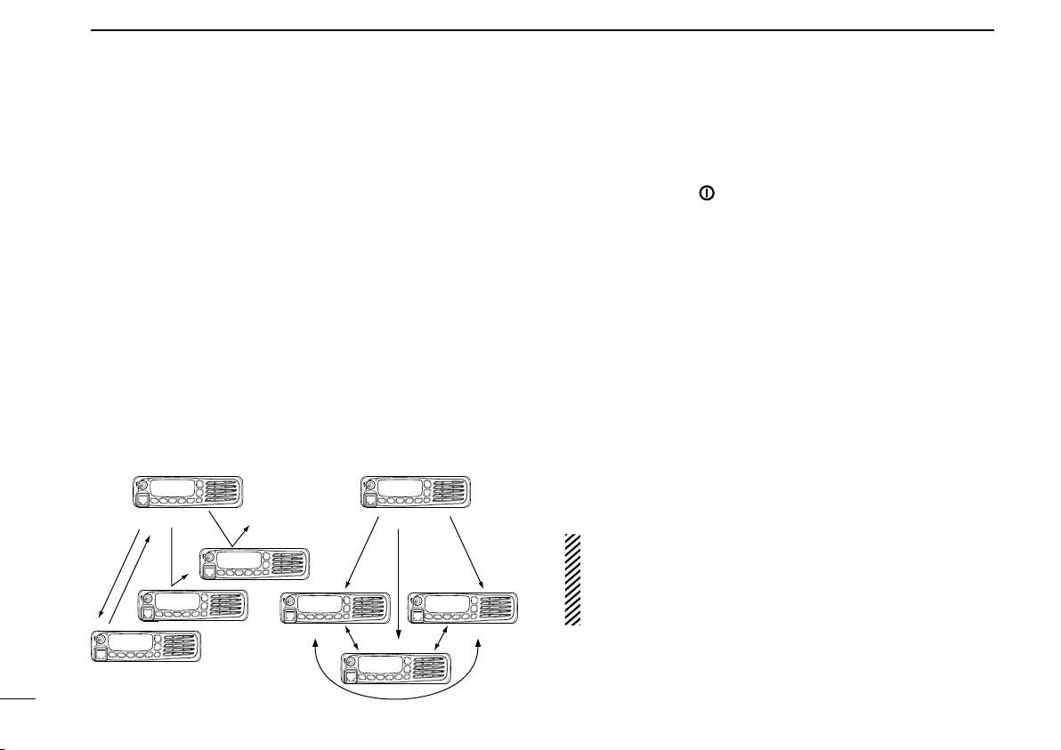
Selective calling
Non-selective calling
2
■ Call procedure
Wh en your syste m emp loys tone signal ing ( ex cluding
CTCSS and DTCS), a call procedure may be necessary
prior to voice transmission. The tone signalling employed
may be a selective calling system which allows you to call
specific station(s) only and prevent unwanted stations from
contacting you.
q Select the desired TX code channel, 2/5-tone code ac-
cording to your System Operator’s instructions.
• This may not be necessary depending on programming.
• Refer to pages. 10–11 for selection.
w Push [Call] (assigned to one of the dealer programmable
keys).
e After transmitting, the remainder of your communication
can be carried out in the normal fashion.
■ Receiving and transmitting
Receiving:
q Push and hold [ ] for 1 sec. to turn the power ON.
w Push [CH Up] or [CH Down] to select the conventional
system channel, in sequence.
e When receiving a call, rotate [VOL] to adjust the audio
output level to a comfortable listening level.
Transmitting:
Wait for the channel to become clear to avoid interference.
q Take the microphone off hook.
• 2/5-tone mute may be released. (The ‘audible’ condition is selected and BUSY indicator lights green.)
• A priority channel may be selected automatically.
w Wait for the channel to become clear.
• The channel is busy when BUSY indicator lights green.
e While pushing and holding [PTT], speak into the micro-
phone at your normal voice level.
r Release [PTT] to return to receive.
IMPORTANT: To maximize the readability of your signal;
1. Pause briefly after pushing [PTT].
2. Hold the microphone 5 to 10 cm (2 to 4 inches) from
your mouth, then speak into the microphone at a nor
mal voice level.
-
9
Page 15

BASIC OPERATION
2
D Transmitting notes
• Transmit inhibit function
The transceiver has several inhibit functions which restrict
transmission under the following conditions:
- The channel is in mute condition (‘Inaudible’ condition;
“ ” (Audible indicator) does not appear.)
- The channel is busy.
- Un-matched (or matched) CTCSS is received.
(Depending on the pre-setting)
- The selected channel is a ‘receive only’ channel.
• Time-out timer
After continuous transmission for the pre-programmed time
period, the time-out timer is activated, causing the trans
ceiver to stop transmitting.
• Penalty timer
Once the time-out timer is activated, transmission is further
inhibited for a period determined by the penalty timer.
D TX code channel selection
If the transceiver has [TX Code CH Select] assigned to it,
the indication can be toggled between the operating channel
number (or name) and TX code channel number (or name).
When the TX code channel number (or name) is displayed,
[CH Up] or [CH Down] selects the TX code channel.
USING [TX CODE CH SELECT] KEY:
q Push [TX Code CH Select]— a TX code channel number
(or name) appears.
w Push [CH Up] or [CH Down] to select the desired TX code
channel.
e After selecting, push [TX Code CH Select] to set.
• Return to the stand-by mode.
-
r Push [Call] to transmit the selected TX code.
USING [TX CODE CH UP]/[TX CODE CH DOWN] KEY:
If the transceiver has a [TX Code CH Up] or [TX Code CH
Down] key assignment, the programmed TX code channel
can be selected directly when pushed.
1
2
3
4
5
6
7
8
9
10
11
12
13
14
15
16
10
Page 16

BASIC OPERATION
2
D TX code number edit (PMR operation only)
If the transceiver has [TX Code CH Select] or [TX Code
Enter] assigned to it, TX code contents can be edited within
the allowable digits.
USING [TX CODE CH SELECT] KEY:
q Push [TX Code CH Select] to enter the TX code channel
selection mode.
• Select the desired operating channel before entering the TX
code channel selection mode if necessary.
w Push [TX Code CH Select] for 1 sec. to enter the TX code
edit mode.
• The digit to be edited blinks.
e Push [TX Code CH Select] to select the desired digit to
be edited.
r Push [CH Up] or [CH Down] to select the desired digit.
t Push [TX Code CH Select] to set. The digit to the right will
blink automatically.
y Repeat r and t to edit all allowable digits.
u After editing, push [TX Code CH Select] to set.
• Return to the stand-by mode.
i Push [Call] to transmit.
USING [TX CODE ENTER] KEY:
q Push [TX Code Enter] to enter the TX code edit mode.
• The digit to be edited blinks.
w Push [TX Code Enter] to select the desired digit to be ed-
ited.
e Push [CH Up] or [CH Down] to select the desired digit.
r Push [TX Code Enter] to set. The digit to the right will
blink automatically.
t Repeat e and r to edit all allowable digits.
y After editing, push [TX Code Enter] to set.
• Return to the stand-by mode.
u Push [Call] to transmit.
D DTMF transmission
If the transceiver has [DTMF Autodial] assigned to it, the
automatic DTMF transmission function is available. Up to 8
DTMF channels are available.
q Push [DTMF Autodial]— a DTMF channel appears.
w Push [CH Up] or [CH Down] to select the desired DTMF
channel.
e Push [DTMF Autodial] to transmit the DTMF code.
11
Page 17
■ User set mode
[P1] [P2] [ ]
[P0]
[P0] [Up]/[Down]
[ ]
User set mode is accessed with [User Set Mode] and allows
you to set seldom-changed settings. In this case you can
“customize” the transceiver operation to suit your prefer
ences and operating style.
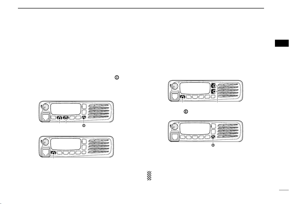
Entering the user set mode:
q While pushing and holding [P1] and [P2], push [ ] to turn
the power ON.
• Turn power OFF in advance.
• You should hold [P1] and [P2] until “SET MODE” appears on
the display.
w Push and hold [P0] for 1 sec. to enter user set mode.
BASIC OPERATION
e Push [P0] several times to select the appropriate item.
Then, push [Up] or [Down] to set the desired level/condi
-
tion.
• Available set mode functions are Backlight, LCD Contrast,
Beep, Beep Level, Ringer Level, SQL Level, AF Min Level,
Mic Gain, Battery Voltage, Horn, Si gnal M oni and Lo ne
Worker.
r Push and hold [ ] for 1 sec. to turn power OFF, then ON
again to exit set mode.
User set mode is also available using a programmable key.
Please refer to p. 7 [User Set Mode] section for instructions
regarding using the key assigned for user set mode.
2
2
-
NOTE: [Up], [Down] and [P0] activate while in the user
set mode regardless of the assigned key functions.
12
Page 18

BASIC OPERATION
2
■ Scrambler function
The voice scrambler function provides private communication between stations. All versions have a built-in frequency
inversion type scrambler; however, an optional rolling or nonrolling type is available as well.
q Push [Scrambler] to turn the scrambler function ON.
• “ ” (Scrambler indicator) appears.
w Push [Scrambler] again to turn the scrambler function
OFF.
• “ ” disappears.
■ Emergency transmission
When [Emergency] is pushed for the specified time period,
an emergency signal is automatically transmitted. (p. 6)
When [Emergency] is pushed for the specified time period,
the DTMF or 5-tone* emergency signal is transmitted once
or repeatedly on the emergency channel. However, when no
emergency channel is specified, the signal is transmitted on
the previously selected channel.
If you want to cancel the emergency call, push and hold the
key again before transmitting the call.
■ Stun function
When the specified ID, set as a kill ID, is received, the stun
function is activated.
When the kill ID is received, the transceiver switches to the
password required condition. Entering of the password (p. 8)
is necessary to operate the transceiver again in this case.
■ Priority A channel selection
When one of the following operations is performed, the
transceiver selects the Priority A channel automatically.
• Turning the power ON
The Priority A channel is selected each time the trans
ceiver power is turned ON.
• Status call
The Priority A channel is selected when transmitting a sta
tus call. (BIIS operation only)
• Off hook.
The Priority A channel is selected when the microhone is
took off from its hanger.
-
-
13
* Depending on the operating model type.
Page 19
CONNECTION AND MAINTENANCE
Antenna
Black
Red
12V
Battery
Solder
Crimp
NOTE: Use the terminals as shown
below for the cable connections.
R CAUT I ON! N E VER r e move
t h e f u se - ho l de r f ro m t he D C
power cable.
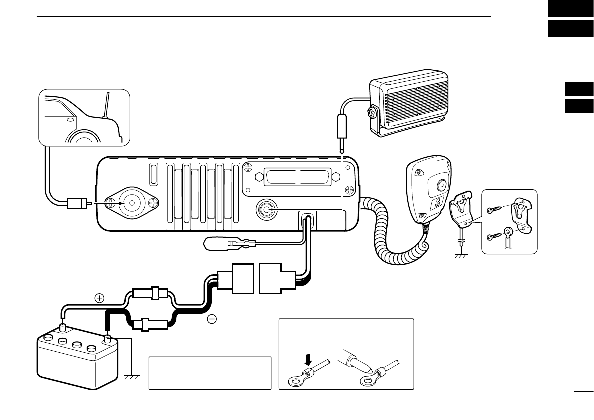
q ANTENNA CONNECTOR
Connects to an antenna.
Contact your dealer about
antenna selection and
placement.
q
e EXTERNAL
SPEAKER JACK
w D-Sub 25-pin
Connect a 4–8 ˘
external speaker.
Connect an external unit.
r MICROPHONE HANGER
Connect the supplied microphone hanger to the
vehicle’s ground for microphone on/off hook
functions. (See p. 1)
t IGNITION LEAD
t
y DC POWER RECEPTACLE
Connects to a 12 V DC battery. Pay attention to polarities. NEVER connect to a 24 V
battery. This will damage the transceiver.
r
y
Optional speaker
w
e
Connects to a ignition line.
R
Do not put a pressure to
this lead.
Binding to the DC power
cable is recommended.
Microphone*
The supplied microphone type is different depending on
the version.
*
3
■ Rear panel connection
1
2
3
4
5
6
7
8
9
10
11
12
13
14
15
16
14
Page 20

Microphone*
1
Microphone hanger
and screw set
Microphone
hanger cable
DC power cable
Sponges*
3
Mounting bracket
Flat washers
Spring washers
Bracket bolts
Mounting screws
(M5×12)
Self-tapping screws
(M5×16)
Nuts
Function name
stickers*
2
*
3
*
2
The microphone type is different depending on
the version.
Used for labelling the programmable function
keys according to their assinged functions.
Used for the optional unit installation.
Ask your dealer for details.
*
1
or
Flat washer
Felt*
Spring washer
When using
self-tapping screws
Felt*
*Felts reduce the vibration effects.
CONNECTION AND MAINTENANCE
3
■ Supplied Accessories
15
■ Mounting the transceiver
The universal mounting bracket supplied with your transceiver allows overhead mounting.
• Mount the transceiver securely with the 4 supplied screws
to a thick surface which can support more than 1.5 kg.
Page 21

CONNECTION AND MAINTENANCE
3
■ Antenna
A key element in the performance of any communication
systems is an antenna. Contact your dealer for more infor
mation regarding antennas and how to install them.
■ Fuse replacement
A fuse is installed in the supplied DC power cable. If a fuse
blows or the transceiver stops functioning, track down the
source of the problem if possible, and then replace the dam
aged fuse with a new rated one.
❑ Fuse rating: 20 A
USE the 20 A fuse only.
■ Cleaning
If the transceiver becomes dusty or dirty, wipe it clean with a
soft, dry cloth.
AVOID
the use of solvents such as benzene or
alcohol, as they may damage the transceiver sur
faces.
■ Options
• RMK-3 separation kit +
-
-
-
OPC-607/OPC-608/OPC-609 separation cable
Allows you to install the transceiver main unit separately from the
front panel for operating convenience.
• OPC-1132/OPC-347 dc power cable
OPC-1132: 3 m (9.8 ft)
OPC-347: 7 m (23 ft)
• HM-152/HM-152T/HM-148 hand microphone
HM-152 : Hand microphone
HM-152T : DTMF microphone
HM-148 : Heavy duty microphone
• SM-25 desktop microphone
• SP-5/SP-10/SP-22 external speaker
Input impedance : 4 ø
Max. input power : 5 W
SP-5 : Large speaker for good audio quality.
SP-10 : For all-round mobile operation.
SP-22 : Compact and easy-to-install.
• UT-109R/UT-110R scrambler units
Non-rolling type (UT-109R)/Rolling type (UT-110R) voice scrambler
unit provides higher communication security.
• UT-96R 5tone unit
• UT-126H digital modulator/demodulator unit
Provides 6.25 kHz digital mode operation.
( UT-126H is a upgrade version of UT-119H. UT-119H can be used
depending on the version. Ask your dealer for details.)
1
2
3
4
5
6
7
8
9
10
11
12
13
14
15
16
16
Page 22
W AR N IN G
CAUTIO N
4
SAFETY TRAINING INFORMATION
17
Your Icom radio generates RF electromagnetic
energy during transmit mode. This radio is designed for and classified as “Occupational Use
Only”, meaning it must be used only during the
course of employment by individuals aware of the
hazards, and the ways to minimize such hazards.
This radio is NOT intended for use by the “General
Population” in an uncontrolled environment.
• For compliance with FCC and Industry Canada RF Exposure Requirements, the transmitter antenna installation shall comply with
the following two conditions:
1. The transmitter antenna gain shall not exceed 0 dBi.
2. IC-F5061/F5061D:
The antenna is required to be located outside of a vehicle and
kept at a distance of 48 centimeters or more between the transmitting antenna of this device and any persons during operation.
For small vehicle as worst case, the antenna shall be located on
the roof top at any place on the centre line along the vehicle in
order to achieve 48 centimeters separation distance. In order to
ensure this distance is met, the installation of the antenna must
be mounted at least 48 centimeters away from the nearest edge
of the vehicle in order to protect against exposure to bystanders.
2. IC-F6061/F6061D:
The antenna is required to be located outside of a vehicle and
kept at a distance of 38 centimeters or more between the transmitting antenna of this device and any persons during operation.
For small vehicle as worst case, the antenna shall be located on
the roof top at any place on the centre line along the vehicle in
order to achieve 38 centimeters separation distance. In order to
ensure this distance is met, the installation of the antenna must
be mounted at least 38 centimeters away from the nearest edge
of the vehicle in order to protect against exposure to bystanders.
To ensure that your exposure to RF electromagnetic energy is within the FCC allowable limits for
occupational use, always adhere to the following
guidelines:
• DO NOT operate the radio without a proper antenna attached,
as this may damage the radio and may also cause you to exceed
FCC RF exposure limits. A proper antenna is the antenna supplied
with this radio by the manufacturer or an antenna specifically authorized by the manufacturer for use with this radio.
• DO NOT transmit for more than 50% of total radio use time (“50%
duty cycle”). Transmitting more than 50% of the time can cause
FCC RF exposure compliance requirements to be exceeded. The
radio is transmitting when the “TX indicator” lights red. You can
cause the radio to transmit by pressing the “PTT” switch.
Electromagnetic Interference/Compatibility
During transmissions, your Icom radio generates RF energy that can
possibly cause interference with other devices or systems. To avoid
such interference, turn off the radio in areas where signs are posted
to do so. DO NOT operate the transmitter in areas that are sensitive
to electromagnetic radiation such as hospitals, aircraft, and blasting
sites.
Page 23

MEMO
1
2
3
4
5
6
7
8
9
10
11
12
13
14
15
16
Page 24

A-6565D-1EX-e
Printed in Japan
© 2006–2008 Icom Inc.
Printed on recycled paper with soy ink.
1-1-32 Kamiminami, Hirano-ku, Osaka 547-0003, Japan
 Loading...