

Page 1
SPECIFICATIONS
CACHET REVENDEUR
ICOM FRANCE
Zac de la Plaine - 1, Rue Brindejonc des Moulinais
BP 45804 - 31505 TOULOUSE CEDEX 5
Tél : 05 61 36 03 03 - Fax : 05 61 36 03 00
WEB ICOM : http://www.icom-france.com
E-mail : icom@icom-france.com
Les spécifications et informations données dans ce document peuvent être modifiées sans préavis.
IDAS™ dPMR™ Features
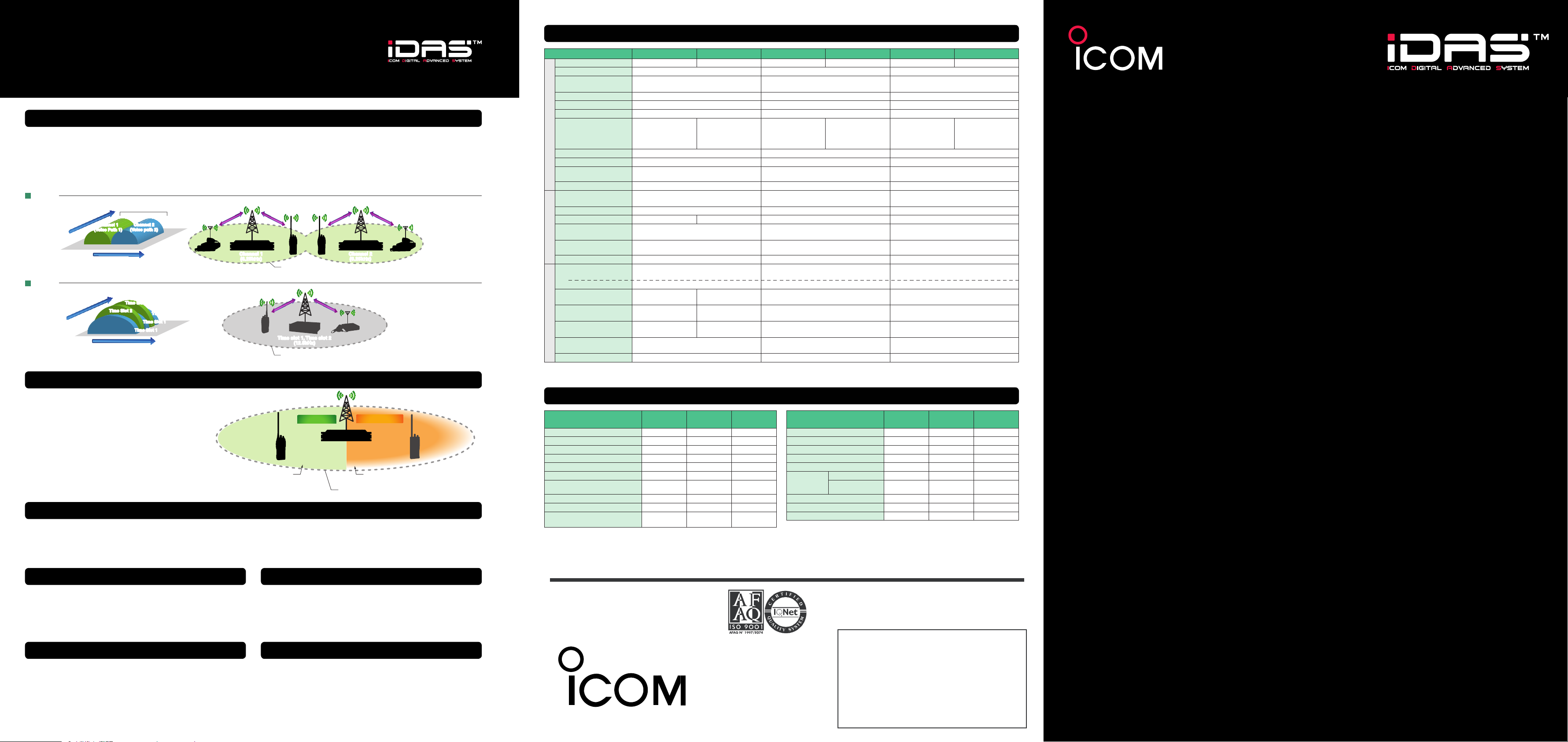
6.25kHz narrowband FDMA technology
IDAS dPMR radios only use 6.25kHz per channel. In general,
the narrower the channel, the better the sensitivity becomes,
and longer communication ranges can be obtained. Where
installation conditions allow, FDMA system can be deploy two
repeater sites using two 6.25kHz channels to greater increase
FDMA
12.5kH z
Time Slot 2
Channel 2
(Voice path 2)
Time Slot 2
Time Slot 1
Time Slot 1
Time Slot 1
Channel 1
(6.25kHz)
Channel 1
(Voice Path 1)
Time
Frequen cy
6.25kHz 6.25kHz
6.25 kHz narrowband FDMA
TDMA
Time
Frequen cy
12.5kHz
6.25 kHz equivalent TDMA
Digital signal coverage
the communication coverage in total, but still only using 6.25kHz
spectrum. The spectrum efficiency of FDMA is maintained in
direct peer-to-peer communication at 6.25kHz, where competing TDMA systems require infrastructure to achieve the same
efficiency.
6.25 kHz
narrowband FDMA
Sinc e the channel s of
FDMA repeaters are
comp letely ind epend ent,
radio servic e areas
can be easil y doubled
by setting up another
repea ter site.
Communication Footprint.
Time slot 1, Time slot 2
(12.5kHz)
Communication Footprint.
Channel 2
(6.25kHz)
6.25 kHz
equi valen t TDMA
IC-FR5100 IC-FR6100 IC-F3162DT/DS IC-F4162DT/DS IC-F5062D IC-F6062D
Frequency coverage 136–174MHz 400–470MHz 136–174MHz 400–470MHz 136–174MHz 400–470MHz
Number of channels Max. 32 channels Max. 512 channels/128 zones Max. 512 channels/128 zones
Type of emission
Channel spacing 6.25kHz/12.5kHz/20kHz/25kHz 6.25kHz/12.5kHz/20kHz/25kHz 6.25kHz/12.5kHz/20kHz/25kHz
PLL channel step 2.5kHz, 3.125kHz 2.5kHz, 3.125kHz 2.5kHz, 3.125kHz
Power supply requirement 13.2V DC 7.2V DC (nominal) 13.2V DC
Current drain
Tx High
Rx Max. audio
GENERALTRANSMITTERRECEIVER
Standby
Antenna impedance 50W (Type-N
Operating temperature range
Dimensions
(Projections not included)
Weight (approx.) 5.6kg (approx.) 340g (approx.) (with BP-232N) 1.3kg (approx.)
Output power
(Hi/Low2/Low1 power)
Max. frequency deviation ±5.0/4.0/2.5kHz
Frequency stability ±0.2kHz ±0.5kHz ±1.0ppm ±1.5kHz
Spurious emissions
Audio harmonic distortion
(AF 1kHz 40% deviation)
Ext. microphone connector
Sensitivity
FM (at 20dB SINAD)
Digital (emf, at 5% BER)
Adjacent channel selectivity
Spurious response rejection
Intermodulation rejection
Audio output power
(at 5% distortion)
Ext. speaker connector 2-conductor 3.5 (d) mm/4W
Measurements made in accordance with EN 300 086 (analogue), EN 301 166 (digital).
All stated specications are subject to change without notice or obligation.
(approx.)
(W×H×D)
16K0F3E, 14K0F3E, 8K50F3E,
4K00F1E, 4K00F1D, 4K00F3E
8.0A
1.9A
400mA (Fan, backlight off)
–25°C to +55°C –25°C to +55°C –25°C to +55°C
483×88×260 mm
25W/10W/2.5W (adjustable to 2.5W)
100% duty cycle
(≤1GHz)
0.25µW
1.0µW (>1GHz)
1% typ. (40% deviation) 3% typ. (40% deviation) 3% typ. (40% deviation)
8-pin modular (600
–4dBµV typ.
86/83/77dB typ. (W/M/N)
67dB typ. (digital)
80dB typ. (W/M/N)
90dBµV typ. (digital, emf)
72/72/71dB typ. (W/M/N)
76dBµV typ. (digital, emf)
–6dBµV typ.
3.5W
min.
with a 4W load
16K0F3E, 14K0F3E, 8K50F3E,
4K00F1E, 4K00F1D
7.0A
1.9A
400mA (Fan, backlight off)
× 2) 50W 50W (SO-239)
(W/M/N) ±5.0/4.0/2.5kHz (W/M/N) ±5.0/4.0/2.5kHz (W/M/N)
W
) 9-pin multi-connector (2.2kW) 8-pin modular (600W)
80/78/70dB typ. (W/M/N)
45dB min. (digital)
70dB min. (W/M/N)
70dBµV min. (digital, emf)
70dB typ. (W/M/N)
71dBµV min. (digital, emf)
1.5A
600mA
150mA
53×136×38.5 mm (with BP-232N) 160×45×150 mm
5W/2W/1W 25W/10W/2.5W
0.25µW (≤1GHz)
1.0µW (>1GHz)
–4dBµV typ.
–8dBµV typ.
75/75/68dB typ. (W/M/N) 85/83/75dB typ. (W/M/N)
70dB min. (W/M/N) 90dB typ. (W/M/N)
67dB typ. (W/M/N) 70dB typ. (W/M/N)
500mW typ.
with an 8W load
9-pin multi-connector (8
1.8A
600mA
140mA
W
)
16K0F3E, 14K0F3E, 8K50F3E,
4K00F1E, 4K00F1D
7.0A
1.2A
300mA
0.25µW (≤1GHz)
1.0µW (>1GHz)
–4dBµV typ.
–8dBµV typ.
4.0W typ.
with a 4W load
2-conductor 3.5 (d) mm/4W
7.0A
1.2A
300mA
When comparing digital with analogue FM, the
audio quality of analogue FM gradually deteriorates with static noise as the distance increases.
n
g
i
s
l
a
t
i
g
i
D
g
a
r
e
v
o
c
l
a
On the other hand, IDAS dPMR digital audio
provides static noise free, stable audio for longer
until the fringes of the communication range.
Digital signal is still clearly heard
at the fringes of the coverage footprint.
Digital / analogue mixed mode operation
IDAS dPMR radios have built-in CTCSS/DTCS, 5-Tone and BIIS
1200 signalings and are designed to coexist with analogue radio
systems. IDAS dPMR radios can receive both analogue and dig-
Selective call and group call
IDAS dPMR radios allow you to call individual or group users.
The way of call set-up is similar to the analogue BIIS 1200 system. Analogue users can introduce IDAS dPMR without hesitation or a new learning curve with these new radios.
Data communication
ital mode signals on a single channel. When receives an analogue
call on a channel set to "Mixed-digital", the analogue talk back
function allows you to reply to the call in the analogue mode.
Secure communication
Using digital modulation, the IDAS dPMR radio cannot be easily monitored with an analogue receiver. When secure communication is required, the IDAS system provides a built-in digital
voice scrambler using a 15-bit key (about 32,000 codes).
Up to 16 IDAS™ dPMR™ repeater connection
r
a
e
a
e
Digital mode
A
n
a
l
o
g
Analogue mode
Analogue signal becomes harder to hear through
noise at the edge of the communication range.
Communication Footprint.
u
e
s
i
g
n
a
l
c
o
v
e
r
a
g
e
a
r
e
a
FUNCTION COMPARISON
Features
Individual / Group Call
All Group Call
Digital & Analogue Mixed Mode Operation
Digital & Analogue Mixed Mode Scan
Talk Around
Repeater simplex use (Base station use)
IP Network connection
Emergency Call
Radio Stun/Kill/Revive
GPS position data with voice/Status/
Short data message
Icom, Icom Inc. and the Icom logo are registered trademarks of Icom Incorporated (Japan) in the United States, the United Kingdom, Ger many, France, Spain, Russia, Japan and/or other countries. IDAS and IDAS logo are trademarks
of Icom Incorporated. dPMR and the dPMR logo are trademarks of the dPMR MoU Association. AMBE+2 is a trademark and property of Digital Voice Systems, Inc. All other trademarks are the properties of their respective holders.
IC-FR5100
IC-FR6100
✔ ✔ ✔
✔ ✔ ✔
✔ ✔ ✔
✔ ✔ ✔
− ✔ ✔
✔ − −
✔
(with UC-FR5000)
Rx only
Tx only
Rx only
IC-F3162DT/DS
IC-F4162DT/DS
− −
✔ ✔
✔ ✔
✔ ✔
IC-F5062D
IC-F6062D
Features
Short Data Message (12/100-character)
Status Message (32-Status)
Transparent Data Mode
Digital Colour Code (64-Code)
Digital Voice Scrambler (15-bit key)
Analogue Voice
Scrambler
5-TONE Encode/Decode
BIIS1200 Encode/Decode
CTCSS/DTCS Encode/Decode (Analogue)
Inversion type
Rolling/Non-rolling type
(Analogue)
(Analogue)
IC-FR5100
IC-FR6100
✔ ✔ ✔
✔ ✔ ✔
✔ ✔ ✔
✔ ✔ ✔
✔ ✔ ✔
✔ (built-in) ✔ (built-in) ✔ (built-in)
✔
(with UT-110R/UT-109R)✔(with UT-110R/UT-109R)
✔ ✔ ✔
− ✔ ✔
✔ ✔ ✔
IC-F3162DT/DS
IC-F4162DT/DS
IC-F5062D
IC-F6062D
(with UT-110R/UT-109R)
✔
IDAS dPMR radios provide status call, short data messages
and GPS position data with voice communication. When IDAS
dPMR radios are connected to a PC or other external equipment, the IDAS dPMR transparent data mode provides up to
3,600 bps data communication in a 6.25kHz channel.
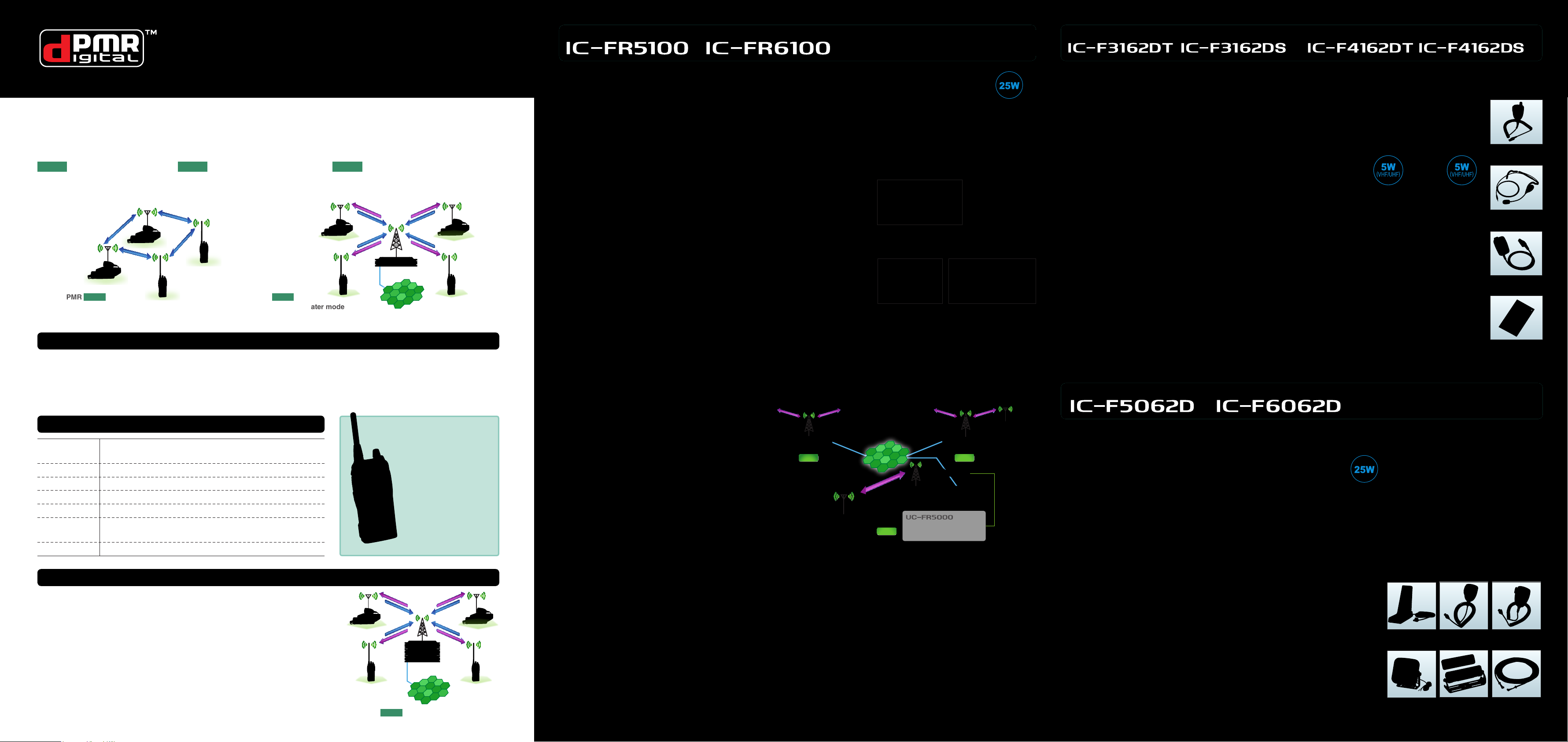
With the optional UC-FR5000 (#12 version required), up to 16
IDAS dPMR repeaters can be interlinked over an IP network to
extend your communication coverage.
Page 2
dPMR™ Introduction and History
dPMR stands for “digital Private Mobile Radio” and it is an open standard digital radio protocol published by the European Telecommunications Standards Institute (ETSI). dPMR utilizes 6.25kHz narrowband FDMA technology with the
AMBE+2™ voice codec that offers many forms of voice and data applications.
The dPMR standard (TS 102 658) has three operating modes:
Mode 1
Direct peer-to-peer mode
IDAS dPMR products support basic conventional Mode 1 and Mode 2 operation at this stage.
Mode 1 Mode 2
dPMR
Peer-to-peer mode
dPMR™ MoU (Memorandum of Understanding) Group
The dPMR standard is delivered by the initial responsibility of
the dPMR MoU group under the mandate of ETSI. The dPMR
MoU group selected the standard vocoder and will perform interoperability and conformance testing using ETSI standards.
Mode 2
Conventional repeater mode
dPMR
Conventional repeater mode
Through the evaluation testing, dPMR equipments will interoperate with each other, ensuring longevity of the system and a
good return on investment.
Mode 3
Centralized trunked network mode
IP Network
VHF DIGITAL/ANALOGUE REPEATER UHF DIGITAL/ANALOGUE REPEATER
Features
• Frequency coverage : 136–174MHz, 400–470MHz
• Number of channels : Max. 32 channels
• 19-inch rack mount design, 2U height low prole design
• 12-digit dot-matrix display and 32 memory channels
• IDAS dPMR mode and analog FM mode, mixed mode operation
• Multiple CTCSS, DTCS tone and digital Colour code decode
• 25W output power at 100% duty operation
• ±0.5ppm high stability oscillator
• “2 channel in 1 box” conguration (Optional UR-FR5100/UR-FR6100 required)
• 5-Tone and DTMF encoder/decoder (5-Tone is for analogue FM mode)
• D-Sub 25-pin accessory connector for connecting analogue trunking controllers
or other external devices
• Audio compander (For analogue FM mode)
• Built-in inversion type voice scrambler and optional UT-109R/UT-110R for higher
security (For analogue FM mode)
• CW ID transmitter
Communication link for distant locations
Options
UC-FR5000 (#12)
IDAS dPMR Network Controller
For IDAS dPMR IP networking
UR-FR5100 (136–174MHz)
UR-FR6100 (400–470MHz)
Channel Modules
Two RF units can be installed in the
unit. (Left side is an option.)
VHF DIGITAL/ANALOGUE TRANSCEIVERS
UHF DIGITAL/ANALOGUE TRANSCEIVERS
Features
• Frequency coverage: 136–174MHz, 400–470MHz
• Compatibility with dPMR mode 1/2
• IDAS dPMR and analog FM mixed mode operations
• 512 memory channels with 128 zones
• Dot matrix, multi-function LCD
• Large capacity Lithium-Ion battery pack
• Dust-protection and waterjet resistance equivalent to IP55
• MIL-STD rugged construction
• 5W RF output power (VHF and UHF)
• Operating time: 14 hours*
* Tx: Rx: standby=5:5:90. Power save on. (at 20°C)
• Loud speaker audio with BTL amplier
• Audio compander (For analogue FM mode)
• 32 status message memories with ambience listening, radio stun/kill/
revive functions (For IDAS dPMR mode)
•
Up to 100 characters short data message memories (For IDAS dPMR mode)
•
Built-in 5-Tone/CTCSS/DTCS/BIIS 1200 signaling (For analogue FM mode)
• 8 DTMF autodial memories
• Built-in inversion type voice scrambler and optional UT-109R/ UT-110R for
higher security (For analogue FM mode)
• Optional GPS speaker-microphone for sending position data
• Voting scan automatically selects the strongest station or the rst station
to exceed the preset signal level
VHF DIGITAL/ANALOGUE TRANSCEIVER
(approx. with BP-232N battery pack)
UHF DIGITAL/ANALOGUE TRANSCEIVER
T Series
(10-Keypad Version)
S Series
(Simple Keypad Version)
Options
HM-170GP
GPS Speaker-microphone
HS-95
Behind-the-head Headset
VS-1SC
PTT/VOX Unit
UT-124R
Man Down Unit
dPMR™ history and evolution
December 2005
February 2006
March 2007
September 2008
December 2008
November 2009
July 2010
dPMR 446 Tier 1 standard (TS 102 490) was published by
ETSI based on the output of their TG-DMR working group
The rst dPMR446 compatible radio, IC-F4029SDR released
dPMR MoU group was founded with the rst member companies
Four new members joined the dPMR MoU group for a total of nine members
dPMR standard (TS 102 658) was published
dPMR interoperability and conformance testing standards
(TS 102 726) were published
The rst dPMR Tier 2 standard radios, IDAS dPMR radios released
dPMR™ mode 3
The dPMR standard also denes a centralized trunked network mode (Mode 3)
similar to the analogue MPT 1327 trunking in conguration and operation. *
dPMR mode 3 will support
• Multi-channel, multi-site digital radio networks managed by centralized control
channels
• Call queue management using priority call and emergency call
• Call diversion to another radio
• Radio authentication service
*IDAS dPMR products support basic conventional Mode 1 and Mode 2 operation at this stage.
The IC-F4029SDR is a
500mW low power radio
which does not require
individual licensing. The
IC-F4029SDR provides
direct peer-to-peer digital voice + data mode
communication.
IC-F4029SDR
DIGITAL PMR446
TRANSCEIVER
IP Network
Mode 3
Centralized trunked modedPMR
An IDAS dPMR IP net work can extend your
communication coverage and allows you to
communicate like a single site. It lets you connect dispersed sites or different bands over the
IP network. In a building all the way from the
basement to the top oor, radio communication
can be covered using already deployed LAN
cables.
Up to 16 IDAS™ dPMR™ repeater connection
With the optional UC-FR5000 (#12), up to 16 IDAS repeaters can
be interlinked with each other. An IDAS terminal radio user can
communicate with other IDAS terminal radio users using the interlinked repeater sites on the network.
* The IDAS conventional IP network cannot relay voice traffic over the IP
network if the uplink is analogue.
Low bandwidth requirement
By using the AMBE+2™ vocoder compression, an IDAS dPMR
IP network requires only about 13kbps bandwidth per one voice
path in theory. It means a DSL class line is sufficient for the IDAS
SIT E B
IP Network
SIT E A
IDAS™ dPMR Netwo rk Control ler
Provides the ability to interface an IP
network to the IDAS dPMR repeater.
SIT E C
#12
Integrated system for clean and simple installation
The IDAS dPMR IP network requires only the UC-FR5000 (#12)
net work controller which can be installed into the IC-FR5100
series repeater – no control server and no extra rack space is
required. In addition, the repeater and network controller settings
can be remotely maintained and monitored over an IP connected
PC.
dPMR IP network in terms of the Internet connection speed. A
xed IP address is required for each networked repeater.
Features
• Frequency coverage: 136–174MHz, 400–470MHz
• Compatibility with dPMR mode 1/2
• IDAS dPMR and analog FM mixed mode operations
• 512 memory channels with 128 zones
• Large dot matrix display and multi-function LCD
• Detachable front panel with optional RMK-3 and separation cable
• D-Sub 25-pin accessory connector and ignition sensing line
• 25W RF output power
• IP54 dust-protection and splash resistance (Front panel only)
• MIL-STD rugged construction
• Front mounted loud speaker and audio compander for analogue FM mode
• 32 status message memories with ambience listening, radio stun/kill/revive
functions (For IDAS dPMR mode)
• Up to 100 characters short data message memories (For IDAS dPMR mode)
• Built-in 5-Tone/CTCSS/DTCS/BIIS 1200 signaling (For analogue FM mode)
• 8 DTMF autodial memories
• Built-in inversion type voice scrambler and optional UT-109R/UT-110R for
higher security (For analogue FM mode)
• Voting scan automatically selects the strongest station or the first station
to exceed the preset signal level
Options
SM-26
Desktop Microphone
SP-30
External Speaker
Some options may not be available in some countries.
HM-152T
DTMF Microphone
RMK-3
Separation Kit
HM-148G
Hand Microphone
OPC-609
Separation Cable
(1.9m)
 Loading...