

Page 1

OPERATING INSTRUCTIONS
iF5360D
8
NXDN OPERATION <CONVENTIONAL MODE>
7
NXDN OPERATION <TRUNKING MODE>
6 NXDN OPERATION <COMMON>
5 MENU SCREEN
4 SCAN OPERATION
3 ADVANCED OPERATION
2 BASIC OPERATION
1 PANEL DESCRIPTION
INTRODUCTION
VHF DIGITAL TRANSCEIVERS
iF6360D
UHF DIGITAL TRANSCEIVERS
Page 2

i
INTRODUCTION
FOREWORD
Thank you for purchasing this Icom transceiver.
The IDAS™ NXDN™ system operation is built into your
IC-F5360D v h f d igi tal t r a n s c e i v e r s and IC-F6360D
u h f d igi tal tr a n s c e i v e r s .
IMPORTANT
FIRST, CAREFULLY READ INSTRUCTIONS
q PRECAUTIONS and w INSTRUCTIONS that are
provided with the transceiver.
SAVE THIS OPERATING INSTRUCTIONS—
This operating instructions contain additional important
operating instructions for the IC-F5360D v h f di gi tal
t r a n s c e i v e r s and IC-F6360D u h f d ig ital t r a n s c e i v -
e r s .
NOTE
The display contents, and the hold down time period of
some keys, may vary from the description in this manual, depending on the transceiver’s presetting.
Icom, Icom Inc. and the Icom logo are registered trademarks
of Icom Incorporated (Japan) in Japan, the United States,
the United Kingdom, Germany, France, Spain, Russia and/
or other countries.
IDAS is trademark of Icom Incorporated (Japan).
NXDN is a trademark of Icom Incorporated and JVC KENWOOD Corporation.
All other products or brands are registered trademarks or
trademarks of their respective holders.
Page 3

1-1
Section 1
PANEL DESCRIPTION
Front, top and side panels ......................................................1-2
About the Microphone D .............................................................1-2
About the Speaker D ...................................................................1-2
Function display ......................................................................1-3
Programmable function keys .................................................1-4
Page 4
1
PANEL DESCRIPTION
1-2
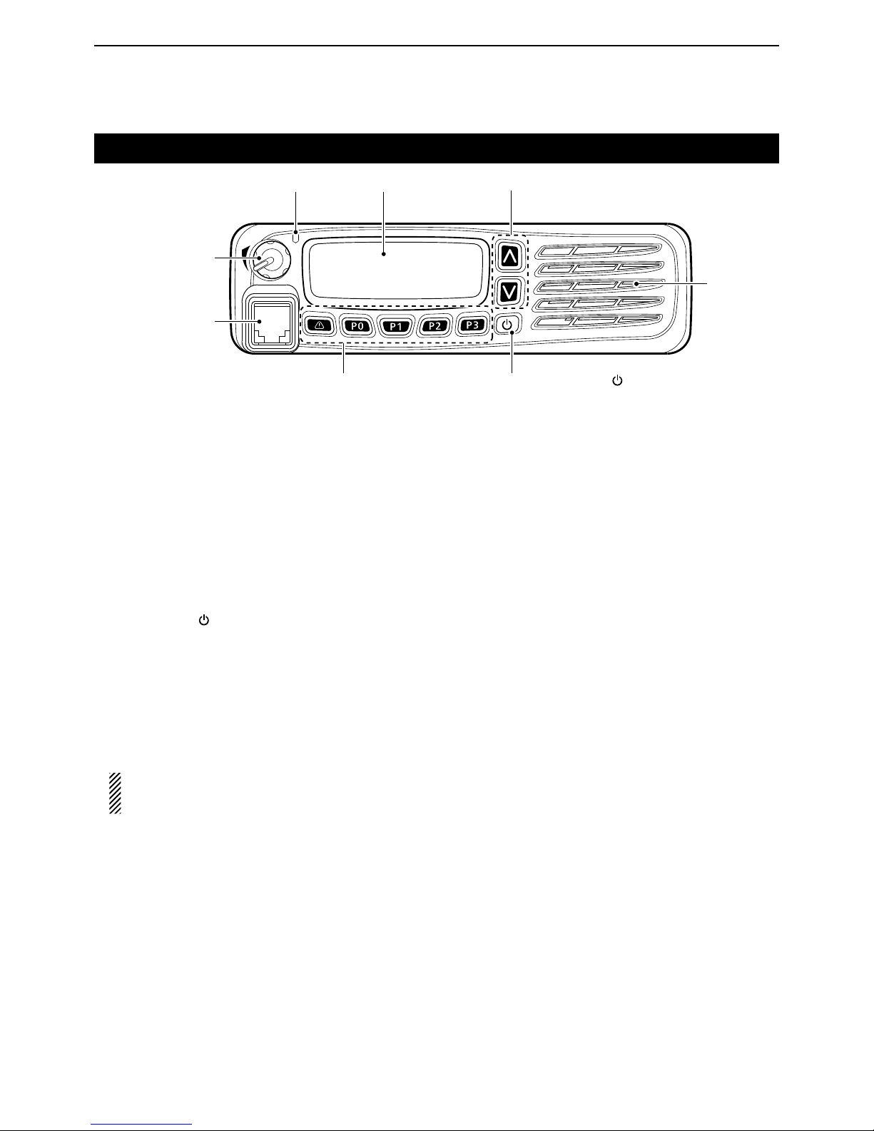
Front, top and side panels
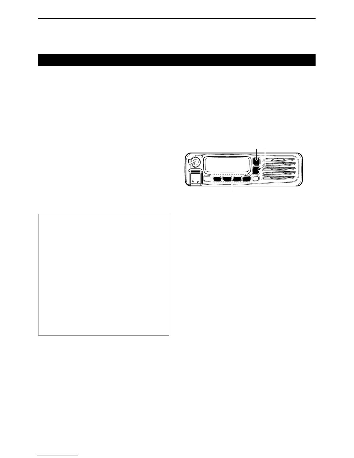
q LED INDICATOR
Lights red while transmitting. ➥
Lights green while receiving a signal, or when the ➥
squelch is open.
w FUNCTION DISPLAY (p. 1-3)
Displays a variety of information.
e DEALER-PROGRAMMABLE KEYS
[UP] and [DOWN]
Desired functions can be preset.
(p. 1-5)
r POWER KEY [ ]
Push and hold for 1 second to turn the power ON
and OFF.
t DEALER-PROGRAMMABLE KEYS
[R], [P0], [P1], [P2], [P3]
Desired functions can be preset.
(p. 1-5)
y MICROPHONE CONNECTOR
Connect the supplied or optional microphone.
NEVER connect non-specified microphones. The
pin assignments may be different and the transceiver may be damaged.
u AF VOLUME CONTROL KNOB [VOL]
Rotate to adjust the audio output level.
About the Microphone D
The supplied or optional microphone has a PTT switch
and a hanger hook.
• The following functions are available when the microphone is on or off hook (depending on the presetting):
- Pauses scan when it is off-hook.
- Switches to the ‘Inaudible’ mode (mute mode) when
it is on-hook.
- Switches to the ‘Audible’ mode (unmute mode)
when it is off-hook.
About the Speaker D
The speaker will be disabled when the External speaker function is ON. (pp. 1-6, 5-3)
u AF VOLUME
CONTROL
KNOB [VOL]
q LED INDICATOR e DEALER PROGRAMMABLE KEYS
[UP], [DOWN]
r POWER KEY [ ]
t DEALER-PROGRAMMABLE KEYS
[R], [P0], [P1], [P2], [P3]
w FUNCTION DISPLAY
SPEAKER
y MICROPHONE
CONNECTOR
Page 5
1
PANEL DESCRIPTION
1-3
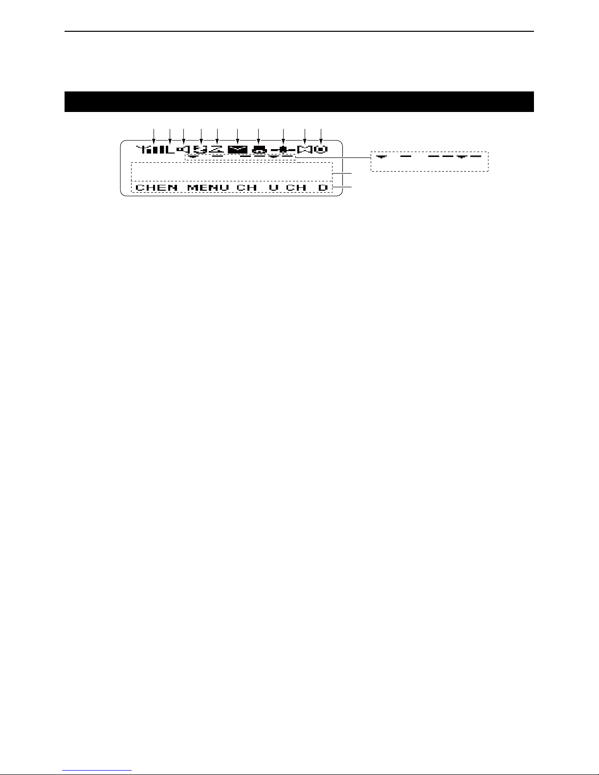
Function display
q SIGNAL STRENGTH INDICATOR
Displays the relative receive signal strength.
w LOW OUTPUT POWER ICON
Displayed when low output power is selected.
e AUDIBLE ICON
Displayed when the channel is in the ‘audible’ (un-
mute) mode.
r SCRAMBLER ICON
Displayed when the Voice Scrambler function is ON.
t SCAN ICON
Displayed while scanning.
y MESSAGE ICON
Displayed when a received message (Short Data ➥
Message or Status Message) is stored in the
memory stack.
Blinks when an unread message is in the memory ➥
stack.
u BELL ICON
Blinks when a matched signal is received, depend-
ing on the presetting.
i GPS ICON
Displayed when position data is received.
o HORN ALERT ICON
Displayed when the Horn Alert function is ON.
!0 PUBLIC ADDRESS ICON
Displayed when the Public Address function is ON.
!1 ALPHANUMERIC READOUT
Displays the operating channel number, channel
name, menu contents, DTMF code, and so on.
• The display mode automatically switches between one
line and two lines.
!2 KEY ICONS
Display the assigned function of the [P0], [P1], [P2]
and [P3] dealer assignable keys.
!3 SCAN TARGET ZONE ICON
Displayed when the scan target zone is selected.
!4 PA SPEAKER ICON
Displayed when the External speaker function is ON.
When the External speaker function is ON, the PA
speaker that is connected to the D-Sub 15-pin will be
enabled.
!5 AUX A ICON
Displayed when the AUX A port is activate.
!6 AUX B ICON
Displayed when the AUX B port is activate.
!7 SCAN TARGET CHANNEL ICON
Displayed when the scan target channel is selected.
!8 OPERATOR SELECTABLE TONE ICON
Displayed when the OST (Operator Selectable Tone)
function is ON.
IC-F5360D
q
w e r t y u i o !0
!2
!1
!3 !4 !5 !6 !7 !8
Page 6
1
PANEL DESCRIPTION
1-4
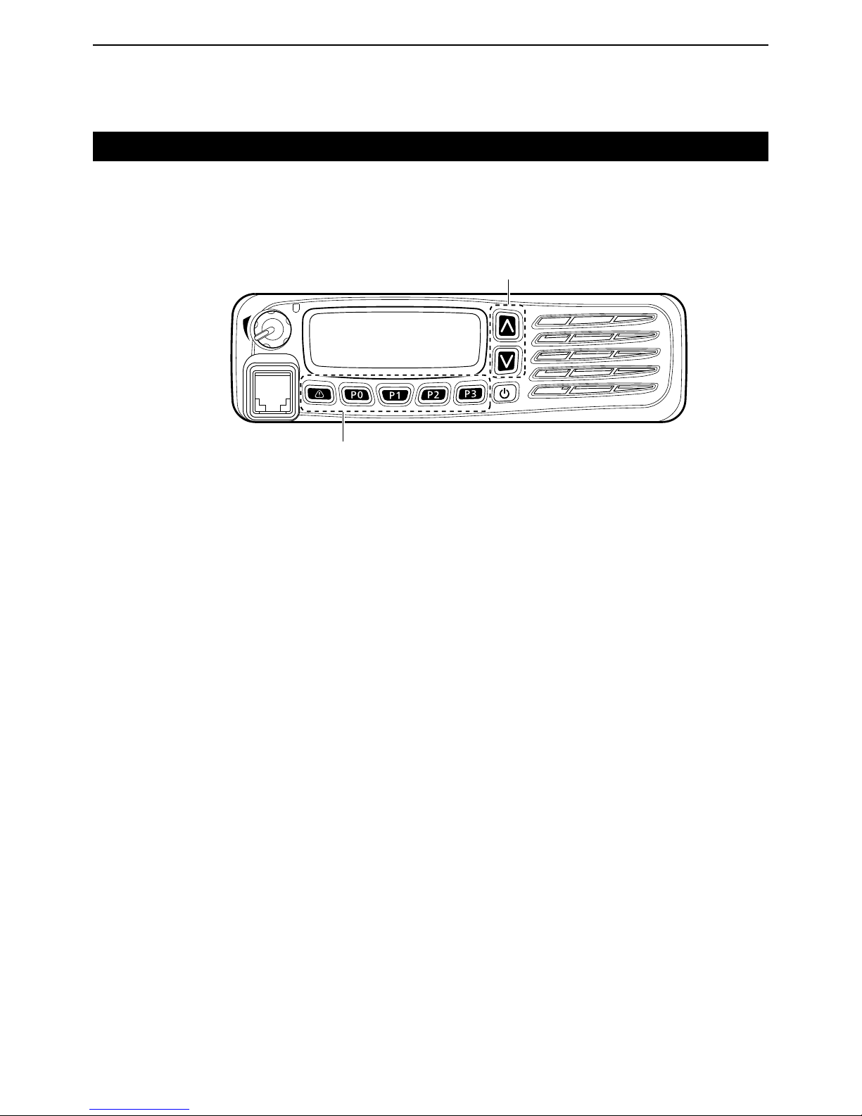
Programmable function keys
The programmable key functions can be assigned to
the following keys:
[R], [P0], [P1], [P2], [P3], [UP], [DOWN] and to the keypad keys of the optional DTMF microphone.
[UP], [DOWN]
[R], [P0], [P1], [P2], [P3]
Page 7

1
PANEL DESCRIPTION
1-5
Programmable function keys (Continued)
• For [R], [P0], [P1], [P2], [P3], [UP] and [DOWN]
The key names that are in quotation marks in the following explanations are displayed on the Function Display, and indicate the assigned function of [P0], [P1],
[P2] and [P3].
None
No function
Autodial “ADAL” (p. 3-2)
Opens the DTMF Autodial code selection screen.
Autodial Programming “ADPG” (p. 3-3)
Enters the DTMF code programming mode.
AUX A “AUXA”
Turns the AUX A port ON or OFF.
AUX B “AUXB”
Turns the AUX B port ON or OFF.
Broadcast “BCST”
Toggles between Broadcast Call and Conference Call.
This key can also be used to make a Broadcast Group
Call.
Call 1 “CAL1”
Sends the NXDN Status, NXDN Individual or the DTMF
code that is set to Call 1.
Call 2 “CAL2”
Sends the NXDN Status, NXDN Individual or the DTMF
code that is set to Call 2.
Call 3 “CAL3”
Sends the NXDN Status, NXDN Individual or the DTMF
code that is set to Call 3.
Call 4 “CAL4”
Sends the NXDN Status, NXDN Individual or the DTMF
code that is set to Call 4.
Call 5 “CAL5”
Sends the NXDN Status, NXDN Individual or the DTMF
code that is set to Call 5.
Call 6 “CAL6”
Sends the NXDN Status, NXDN Individual or the DTMF
code that is set to Call 6.
CH/GID Down “CH D”
Selects the next or previous channel or GID number.
CH/GID Recall “CHRC”
❍ In the Analog mode or
NXDN Conventional system
Selects the last used channel during a scan.
❍
In the NXDN Trunking system
Selects the last called GID during a scan.
CH/GID Up “CH U”
Selects the next or previous channel or GID number.
Channel Entry “CHEN” (p. 2-4)
Enters the Channel Entry mode.
CW Message “CWMS”
Sends a preset CW Message on a ‘very narrow’ channel.
You can use this function when a CW message is preset.
Direct CH/GID 1 “DR 1” (pp. 2-4, 7-3)
Selects the channel or GID that is set to Direct CH/
GID 1.
Direct CH/GID 2 “DR 2” (pp. 2-4, 7-3)
Selects the channel or GID that is set to the Direct CH/
GID 2.
Direct CH/GID 3 “DR 3” (pp. 2-4, 7-3)
Selects the channel or GID that is set to Direct CH/
GID 3.
Direct CH/GID 4 “DR 4” (pp. 2-4, 7-3)
Selects the channel or GID that is set to Direct CH/
GID 4.
Direct CH/GID 5 “DR 5” (pp. 2-4, 7-3)
Selects the channel or GID that is set to Direct CH/
GID 5.
Direct CH/GID 1 Select
This function is for the hold down operation of [Direct
CH/GID 1].
Sets the selected channel or GID to Direct CH/GID 1.
Page 8

1
PANEL DESCRIPTION
1-6
Programmable function keys
Direct CH/GID 2 Select
This function is for the hold down operation of [Direct
CH/GID 2].
Sets the selected channel or GID to Direct CH/GID 2.
Direct CH/GID 3 Select
This function is for the hold down operation of [Direct
CH/GID 3].
Sets the selected channel or GID to Direct CH/GID 3.
Direct CH/GID 4 Select
This function is for the hold down operation of [Direct
CH/GID 4].
Sets the selected channel or GID to Direct CH/GID 4.
Direct CH/GID 5 Select
This function is for the hold down operation of [Direct
CH/GID 5].
Sets the selected channel or GID to Direct CH/GID 5.
Display Format “DISP”
❍ In the Analog mode or
NXDN Conventional system
Toggles the display format between the channel name
and the zone and channel number.
❍
In the NXDN Trunking system
Toggles the display format between the GID name and
the GID number.
Emergency (p. 3-5)
This function can be assigned only for [R].
Enters the Emergency mode.
External Speaker “EXSP”
Turns the External speaker function ON or OFF.
When the External speaker function is ON, the PA
speaker that is connected to the D-Sub 15-pin will be
enabled.
• In this case, the front panel speaker and the speaker that is
connected to the external speaker jack will be disabled.
Fixed Volume “FIXV”
Toggles the tone level between “High” and “Low,” or
turns OFF the tone.
Forced Search “FORS”
Displays the site number of the current site for 2 seconds.
Forced Search Function
This function is for the hold down operation of [Forced
Search].
Activates a Control Channel Hunt.
Function “FUNC”
Activates a secondary function that is assigned to a
key.
This function cannot be assigned as a secondary function.
GPS Position Display “GPSP”
Enters the GPS Position Display mode.
In the GPS Position Display mode, you can check your
latitude and longitude position.
Group ID/Channel Entry “GIDE” (pp. 2-4, 7-3)
❍ In the Analog mode or
NXDN Conventional system
Enters the Channel Entry mode.
❍
In the NXDN Trunking system
Enters the GID Entry mode.
Group (NXDN) “GRP” (pp. 7-4, 8-3)
❍ In the NXDN Conventional system or
the NXDN Trunking system
Enters the Group Call mode.
In the NXDN Conventional system, this function is used
for Group Call by recalling GID list.
In the NXDN Trunking system, the GID List is displayed,
but the transceiver cannot make a call.
Group + SDM (NXDN) “GSMS”
❍ In the NXDN Conventional system or
the NXDN Trunking system
Enters the Group Call mode.
If you push [P1](ENT) while in the Group Call mode,
the transceiver enters the Short Data Message Entry
mode. See page 7-4 or 8-3 for details.
Group + Status (NXDN) “GSTA”
❍ In the NXDN Conventional system or
the NXDN Trunking system
Enters the Group Call mode.
If you push [P1](ENT) while in the Group Call mode,
the transceiver enters the Status Message Entry mode.
See page 7-4 or 8-3 for details.
High Transmit Power “HIPW”
❍
In the NXDN Trunking system
Toggles the transmit power level between “High” and ➥
“Auto,” if “Auto” is set as the default.
Toggles the transmit power level between “High” and ➥
“Low,” if “Low” is set as the default.
• For [R], [P0], [P1], [P2], [P3], [UP] and [DOWN] (Continued)
Page 9

1
PANEL DESCRIPTION
1-7
Programmable function keys
Home CH/GID “HOME” (pp. 2-4, 7-3)
❍ In the Analog mode or
NXDN Conventional system
Selects the Home Channel.
❍
In the NXDN Trunking system
Selects the Home GID.
Home CH/GID Select (pp. 2-4, 7-3)
This function is for the hold down operation of [Home
CH/GID].
❍ In the Analog mode or
NXDN Conventional system
Sets the selected channel as the Home Channel.
❍
In the NXDN Trunking system
Sets the selected GID as the Home GID.
Horn Alert “HORN”
Turns the Horn Alert function ON or OFF.
When this function is ON, the horn alert port will be activated for a preset time period after receiving a call.
Individual (NXDN) “INDV” (pp. 7-5, 7-6, 8-4)
❍ In the NXDN Conventional system or
the NXDN Trunking system
Enters the Individual Call mode.
Individual + SDM (NXDN) “ISMS”
❍ In the NXDN Conventional system or
the NXDN Trunking system
Enters the Individual Call mode.
If you push [P1](ENT) while in the Individual Call mode,
the transceiver enters the Short Data Message Entry
mode. See page 7-5 or 8-4 for details.
Individual + Status (NXDN) “ISTA”
❍ In the NXDN Conventional system or
the NXDN Trunking system
Enters the Individual Call mode.
If you push [P1](ENT) while in the Individual Call mode,
the transceiver enters the Status Message Entry mode.
See page 7-5 or 8-4 for details.
LCD Brightness “BRIT”
Selects the brightness of the function display and keys
backlight. Select High, Low or OFF to meet your needs.
The function display and keys can be backlit for better
visibility under low light conditions.
Lone Worker “LONE” (p. 3-5)
Turns the Lone Worker function ON or OFF.
Low Transmit Power “LOPW”
❍ In the Analog mode or
NXDN Conventional system
Toggles the transmit power between “High” and “Low,” if
“High” is set as the default.
❍
In the NXDN Trunking system
Toggles the transmit power level between “Low” and ➥
“Auto,” if “Auto” is set as the default.
Toggles the transmit power level between “High” and ➥
“Low,” if “High” is set as the default.
Maintenance “MANT”
Enters the Maintenance Display mode.
Menu “MENU” (p. 5-2)
Displays the Menu screen.
Monitor “MONI”
❍ In the Analog mode
Turns the Monitor ON or OFF.
When the Monitor is ON, the transceiver releases the
CTCSS or DTCS mute.
❍ In the NXDN Conventional system
Turns the Monitor ON or OFF.
When the Monitor is ON, the transceiver releases the
RAN code mute.
Monitor Momentary “MONI”
❍ In the Analog mode
While holding down, the transceiver releases the CTCSS mute.
❍ In the NXDN Conventional system
While holding down, the transceiver releases the RAN
code mute.
Operator Selectable Tone “OST”
Turns the OST (Operator Selectable Tone) mode ON
or OFF.
When the OST mode is ON, the selected tone in the
OST list is enabled.
OST List
This function is for the hold down operation of [Operator Selectable Tone].
Displays the OST (Operator Selectable Tone) list.
Priority-channel Select “PRIO”
Enters the Priority channel Select mode for a Priority
scan.
• For [R], [P0], [P1], [P2], [P3], [UP] and [DOWN] (Continued)
Page 10

1
PANEL DESCRIPTION
1-8
Programmable function keys
Public Address “PUBA”
Turns the Public Address function ON or OFF.
When this function is ON, you can make announcement through a PA speaker.
• Transmitting is disabled while in the PA mode.
Scan “SCAN”
Starts or stops a scan.
Scan Delete/Add “SCNE”
Sets or cancels the selected channel or GID as a scan
target.
Scrambler/Encryption “SCRM”
❍ In the Analog mode
Turns the Scrambler function ON or OFF.
❍ In the NXDN Conventional system or
the NXDN Trunking system
Turns the Encryption function ON or OFF.
Scrambler/Encryption Code
This function is for the hold down operation of [Scrambler/Encryption].
❍ In the Analog mode
Enters the Scrambler Code mode.
❍ In the NXDN Conventional system or
the NXDN Trunking system
Enters the Encryption Code mode.
SDM (NXDN) “SMSG”
❍ In the NXDN Conventional system or
the NXDN Trunking system
Directly enters the Short Message mode.
Push [PTT] to send a Short Message to a Base ID.
Send the GPS data “GPSD”
❍ In the NXDN Conventional system or
the NXDN Trunking system
Sends the position data that is received from the GPS
receiver to a Base station.
Site Down “SIDN”
❍
In the NXDN Trunking system
Selects the previous site number.
If the site name is not entered, [Site Down] does not
function.
Site Lock “SILK”
❍
In the NXDN Trunking system
Turns the Site Lock function ON or OFF.
Site Select
This function is for the hold down operation of [Site
Lock].
❍
In the NXDN Trunking system
Enters the Site Select mode.
If the site name is not entered, [Site Select] does not
function.
Site Up “SITU”
❍
In the NXDN Trunking system
Selects the next site number.
If the site name is not entered, [Site Up] does not function.
Squelch Level “SQLL”
❍ In the Analog mode
Enters the Squelch Level Adjustment mode.
Squelch Off “SQLO”
❍ In the Analog mode or
NXDN Conventional system
Opens the squelch, and releases the mute.
Squelch Off Momentary “SQLM”
❍ In the Analog mode or
NXDN Conventional system
While holding down, opens the squelch, and releases
the mute.
Stack “STAK” (p. 6-3)
Enters the Memory Stack mode.
Status (NXDN) “STAT”
Enters the Status Message mode.
Push [PTT] to send a Status to a Base ID.
Talk Around “TLKA”
Turns the Talk around function ON or OFF.
• The Talk around function equalizes the transmit frequency
to the receive frequency for transceiver-to-transceiver communication.
Transceiver Password “PSWD” (p. 2-2)
Enters the password entry mode.
The transceiver cannot be used until you enter a correct password.
Zone Delete/Add “ZODE”
Sets or cancels the selected zone as a scan target.
Zone Down “ZNDN”
Selects the previous zone number.
Zone Up “ZNUP”
Selects the next zone number.
• For [R], [P0], [P1], [P2], [P3], [UP] and [DOWN] (Continued)
Page 11

1
PANEL DESCRIPTION
1-9
• For Keypad Operation (Microphone)
Channel Entry (p. 2-4)
Enters the channel number.
Group ID/Channel Entry (pp. 2-4, 7-3)
❍ In the Analog mode
❍ In the NXDN Conventional system
Enters the channel number.
❍
In the NXDN Trunking system
Enters the GID.
OST (Operator Selectable Tone)
Hold down [1] to [9] to select a tone that is preset in ➥
the OST list.
Hold down [0] to turn OFF the OST tone. ➥
Hold down [ ➥ M] to turn OFF the OST mode.
• When the OST mode is OFF, the selected channel’s pre-
set tone is used.
Hold down [#], and then push the [0] to [9] digit keys ➥
to enter the OST List number 1 to 40 to select a preset tone.
Autodial
Selects the DTMF Code that is preset in the Autodial
List.
After selecting, push [PTT] to send.
Keypad Auto PTT
Transmits DTMF tones.
This function is enabled only when Manual Dialing is
enabled.
Status (NXDN)
❍ In the NXDN Conventional system
❍
In the NXDN Trunking system
Enters the Status Message mode, and selects the Status number.
SDM (NXDN)
❍ In the NXDN Conventional system
❍
In the NXDN Trunking system
Enter an SDM message.
Individual (NXDN)
❍ In the NXDN Conventional system
❍
In the NXDN Trunking system
Enters the Individual Call mode, and selects the unit ID
to send an Individual Call to.
Individual + Status (NXDN)
❍ In the NXDN Conventional system
❍
In the NXDN Trunking system
Enters the Individual Call mode, and selects the unit ID
to transmit an Individual Call to.
If you push [P1](ENT) while in the Individual Call mode,
the transceiver enters the Status Message mode.
Individual + SDM (NXDN)
❍ In the NXDN Conventional system
❍
In the NXDN Trunking system
Enters the Individual Call mode, and selects the unit ID
to transmit an Individual Call to.
If you push [P1](ENT) while in the Individual Call mode,
the transceiver enters the Short Data Message mode.
Group (NXDN)
❍ In the NXDN Conventional system
Enters the Group Call mode, and selects the GID to
send a Group Call to.
❍
In the NXDN Trunking system
Displays the GID List, but the transceiver cannot make
a call.
Group + Status (NXDN)
❍ In the NXDN Conventional system
❍
In the NXDN Trunking system
Enters the Group Call mode, and selects the GID to
transmit a Group Call to.
If you push [P1](ENT) while in the Group Call mode, the
transceiver enters the Status Message mode.
Group + SDM (NXDN)
❍ In the NXDN Conventional system
❍
In the NXDN Trunking system
Enters the Group Call mode, and selects the GID to
transmit a Group Call to.
If you push [P1](ENT) while in the Group Call mode, the
transceiver enters the Short Data Message mode.
Programmable function keys (Continued)
Page 12

2-1
Section 2
BASIC OPERATION
Turning power ON ....................................................................2-2
Adjusting the audio level D ..........................................................2-2
Inputting the password D ............................................................2-2
Selecting a zone ......................................................................2-3
Selecting a zone D ......................................................................2-3
Selecting a channel .................................................................2-4
Selecting a channel D .................................................................2-4
Selecting a Home channel D ......................................................2-4
Directly entering a channel D ......................................................2-4
Receiving ..................................................................................2-5
Setting the squelch level D ..........................................................2-5
Transmitting .............................................................................2-6
Transmitting notes D ...................................................................2-6
Page 13
2
BASIC OPERATION
2-2
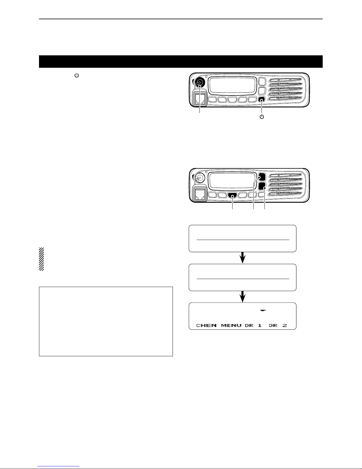
Turning power ON
Hold down [ ➥ ] for 1 second to turn ON the power.
Adjusting the audio level D
When receiving a call, rotate [VOL] to adjust the au- ➥
dio output volume level.
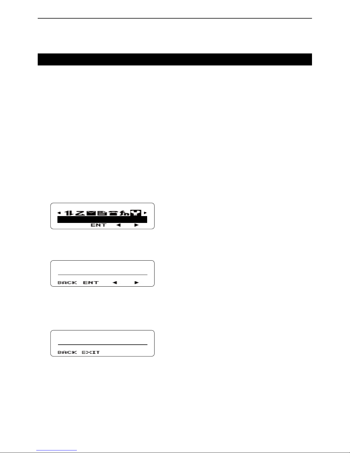
Inputting the password D
If the transceiver is preset for a start up password, enter the digit codes.
While in the Password Entry mode, “PASSWORD” q
is displayed.
Push [UP] or [DOWN] to enter a digit code, and then w
push [P1] to set.
• Goes to the next digit entry position.
Repeat step e w until you enter the password, and
then push [P1].
When using the DTMF microphone:
Push the [0] to [9] digit keys on the microphone to enter
the password, and then push [#].
NOTE: If “PASSWORD” does not disappear after
pushing [P1], the password code you entered may
be incorrect. In this case, enter the correct password.
For your reference:
When [Transceiver Password] is assigned to any key,
or the Transceiver Password item is preset in the
Menu screen and [Menu] is assigned to any key, the
start up password does not appear, even if the Transceiver Password is programmed.
In this case, push [Transceiver Password], or select
“Transceiver Password” in the Menu screen to enter
the Password Entry mode, then enter the password
as described above.
PASSWORD
12345
Channel 1
[VOL]
[ ]
[P1]
[UP] [DOWN]
Page 14

2
BASIC OPERATION
2-3
Selecting a zone
Selecting a zone D
To select a desired zone (Conventional group or NXDN
Trunking system).
Push [Zone Up] or [Zone Down]. ➥
NOTE:
When you select the Conventional group zone, see
the page 2-4 for details of the channel selection.
When you select the NXDN Trunking system zone,
see page 7-3 for details of the GID (Group ID) selection.
For your reference: What is “zone?”
Certain channels are grouped together and assigned
to a zone according to their intended use.
For example, ‘Staff A’ and ‘Staff B’ are assigned to a
“Business” zone, and ‘John’ and ‘Cindy’ are assigned
to a “Private” zone.
Page 15
2
BASIC OPERATION
2-4
Selecting a channel
Selecting a channel D
To select a desired operating channel:
Push [CH/GID Up] or [CH/GID Down]. ➥
Push one of the direct channel select keys, [Direct ➥
CH/GID 1] to [Direct CH/GID 5].
• You can change the channel by pushing [Direct CH/GID
1] to [Direct CH/GID 5], as described below.
Changing the Direct channel setting:
Select a desired channel. q
Hold down one of the [Direct CH/GID 1] to [Direct w
CH/GID 5] keys for 3 seconds to set the selected
channel to the Direct channel 1 to 5.
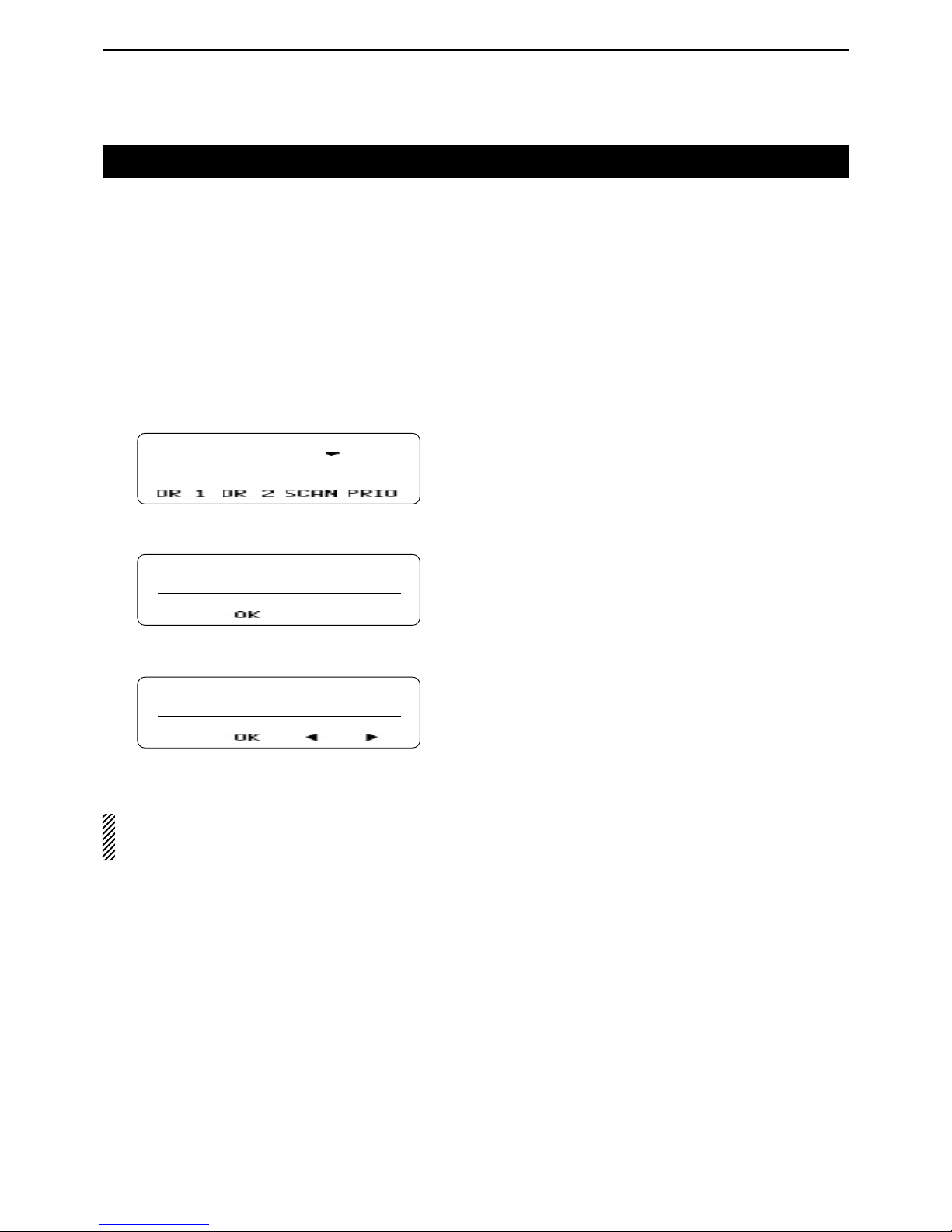
Directly entering a channel D
You can select a channel by pushing [UP] or [DOWN] or
the [0] to [9] digit keys on the microphone, after pushing
[Channel Entry].
Or, when the Channel Entry function is assigned to the
keypad, you can select a channel by pushing [0] to [9]
digit keys on the microphone.
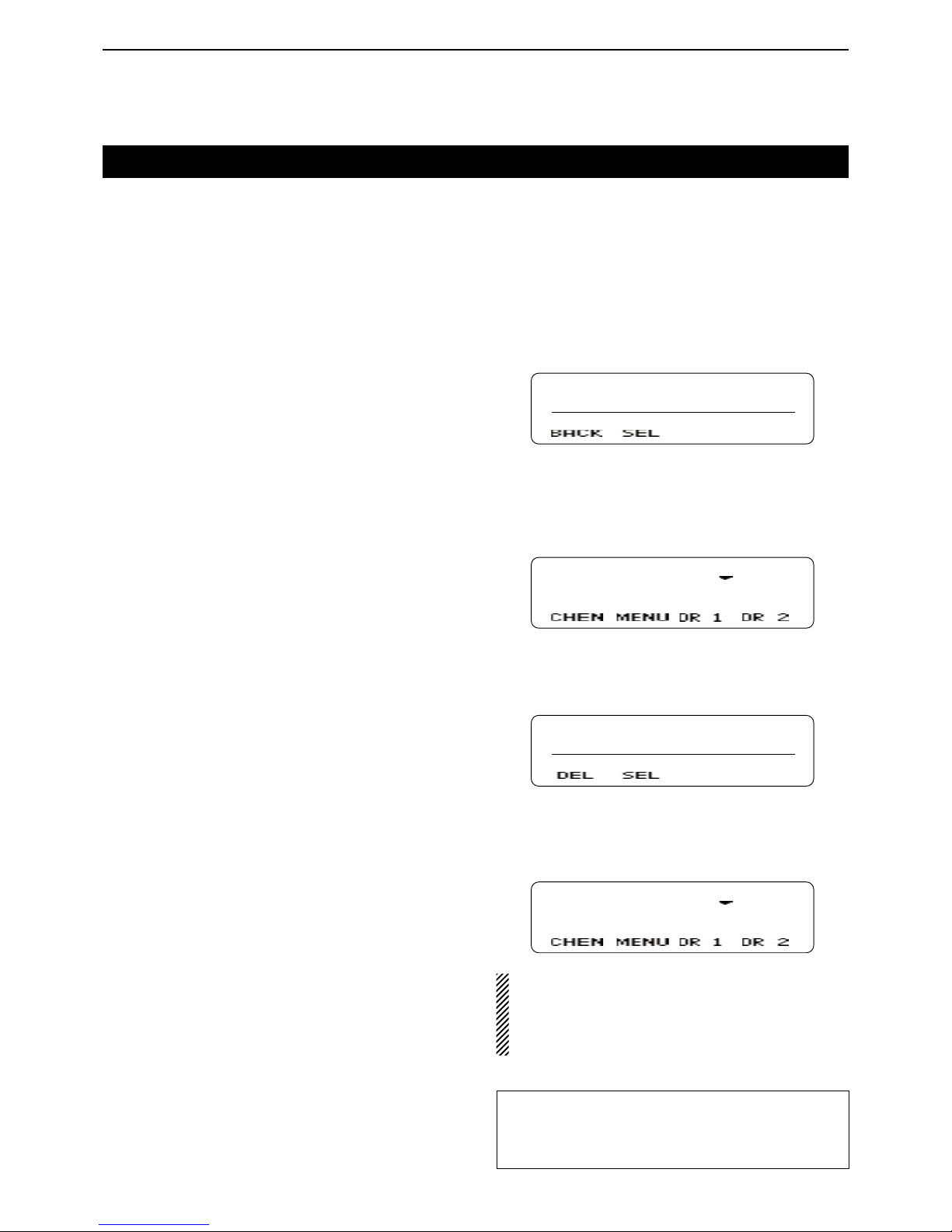
Push [Channel Entry] to enter the Channel Entry q
mode.
CH ENTER MOD
CH No. _ _
w
Push [UP] or [DOWN] to select
the channel number,
and then push [P1](SEL).
• Push [P0](BACK) to cancel the entry, and return to the
screen that you selected before entering the Channel Entry mode.
• You can use the digit keys on the microphone.
Channel 1
When using the DTMF microphone:
Push the [0] to [9] digit keys to enter the Channel q
Entry mode.
CH ENTER MOD
CH No. _ 1
Enter the channel number, and then push [#]. w
• Push [M] to delete the entered number.
• Push [M] again to cancel the entry, and return to the
screen that you selected before entering the Channel
Entry mode.
Channel 1
• When the channel name is not programmed, the
selected zone and channel number are displayed.
(example: “1- 1”)
• When the programmed channel is less than 10, you
can select a channel without pushing [#].
Selecting a Home channel D
The Home channel is an often-used Memory channel
you can preset in the transceiver.
Push [Home CH/GID]. ➥
• To change the Home channel, see the description
below.
Changing the Home channel setting:
Select a desired channel. q
Hold down [Home CH/GID Select] for 3 seconds to w
set the selected channel as the Home channel.
For your reference:
You may be able to select a channel in the Menu
screen, depending on the presetting.
See section 5 for details.
Page 16
2
BASIC OPERATION
2-5
Receiving
Select a channel. (p. 2-4) q
Push [CH/GID Up] or [CH/GID Down]. ➥
Push one of the direct channel select keys, [Direct ➥
CH/GID 1] to [Direct CH/GID 5].
Push the [0] to [9] digit keys of the optional DTMF ➥
microphone to enter the channel number when
the Channel Entry function is assigned to the keypad, or after pushing [Channel Entry].
When receiving a call, rotate [VOL] to adjust the au- w
dio output volume level.
Setting the squelch level D
The squelch circuit mutes the received audio, depending on the signal strength.
Push [MENU]. q
• Opens the Menu screen.
Push [P2]( w Ω) or [P3](≈) to select the category that
has the “SQL LEVEL” item. (Default: “UTILITY”)
UTILITY
Push [P1](ENT). e
• Enters the Menu Item Select mode.
Push [P2]( r Ω) or [P3](≈) to select the “SQL LEVEL”
item.
UTILITY
SQL LEVEL
Push [P1](ENT). t
• Enters the Squelch Level Adjustment mode.
Push [UP] to increase the squelch level up to 9 (tight y
squelch) or push [DOWN] to decrease the squelch
level down to 0 (loose squelch).
• Push [P0](BACK) to return to the previous screen.
LEVEL 9
After setting, push [P1](EXIT). u
• Closes the Menu screen.
Page 17

2
BASIC OPERATION
2-6
Transmitting
Wait until the channel is clear to avoid interference.
Take the microphone off-hook. q
• While scanning, the scan stops.
Wait for the channel to become clear. w
• The channel is busy when the LED indicator lights green.
While holding down [PTT], speak at a normal voice e
level.
Release [PTT] to receive. r
NOTE:
To maximize the readability of your signal:
1. After pushing [PTT], pause briefly before you start
speaking.
2. Hold the microphone 5 to 10 cm (2 to 4 inches)
from your mouth, then speak at your normal voice
level.
Transmitting notes D
• Transmit inhibit function
The transceiver has several inhibit functions which restrict transmission under the following conditions:
- The channel is busy.
- An unmatched CTCSS tone or DTCS code is received, depending on the presetting.
- An unmatched or matched RAN code is received,
depending on the presetting.
- The selected channel is a ‘receive only’ channel.
• Time-out timer (TOT)
After continuous transmission for a preset time period, the time-out timer causes the transceiver to stop
transmitting.
• TOT Rekey timer
Once transmission is cut OFF, it is further inhibited for
a period determined by the TOT Rekey timer.
• MDC 1200 system operation
The MDC 1200 signaling system enhances your transceiver’s capabilities. It allows PTT ID signaling.
When you push or release [PTT], the transceiver
sends your unit ID, if preset.
ID 0001
When receiving a PTTID
from unit ID ‘0001.’
Page 18

3-1
Section 3
ADVANCED OPERATION
DTMF Calls ...............................................................................3-2
Manual Dialing D .........................................................................3-2
Autodial D ...................................................................................3-2
Stun function D ...........................................................................3-2
Editing the Autodial list D ............................................................3-3
Adding an entry to the Autodial list D ..........................................3-4
Emergency Calls ......................................................................3-5
Emergency Calls D .....................................................................3-5
Lone Worker Emergency Call D ..................................................3-5
Scrambler .................................................................................3-6
Radio Access Number (RAN) .................................................3-7
Page 19
3
ADVANCED OPERATION
3-2
DTMF Calls
Manual Dialing D
While holding down [PTT], push the keys on the ➥
10-keypad to send the desired DTMF tones.
• When [Keypad Auto PTT] is assigned to the keypad, you
can send the DTMF tones using the DTMF keypad without pushing [PTT].
Autodial D
Autodial allows you to quickly send DTMF tones that
have been pre-entered onto your transceiver.
Push [Autodial]. q
• The rst entry in the Autodial list appears.
Push [UP] or [DOWN] to select your desired num- w
ber.
Push [P3](TX) or [PTT] to send. e
Stun function D
When the transceiver receives a stun code over the air,
the stun function is activated and the transceiver operation is inhibited. In this case, receiving a revive code is
necessary to operate the transceiver again.
This function is used when a transceiver is stolen or
lost.
For your reference:
When the Store & Send function is enabled, you can
sequentially send up to 30 of DTMF tones at one
time.
Push [Autodial]. q
• “CODE?” appears.
Push [UP] or [DOWN] to enter a digit, and then w
push [P1](SEL) to set.
• Goes to the next digit entry position.
• You can use the 10-keypad keys of the optional DTMF
microphone to enter a digit.
Repeat step e w until you enter up to 30 digits.
• Push [P0](DEL) to delete the entered digit.
• Push [P1](EXIT) to exit the DTMF Code Entry mode.
• Push [P2](MODE) to toggle between the DTMF Code
Entry mode and the DTMF Autodial code selection
mode.
Push [P3](TX) or [PTT] to send. r
[P0], [P1], [P2], [P3]
[UP] [DOWN]
Page 20

3
ADVANCED OPERATION
3-3
DTMF Calls (Continued)
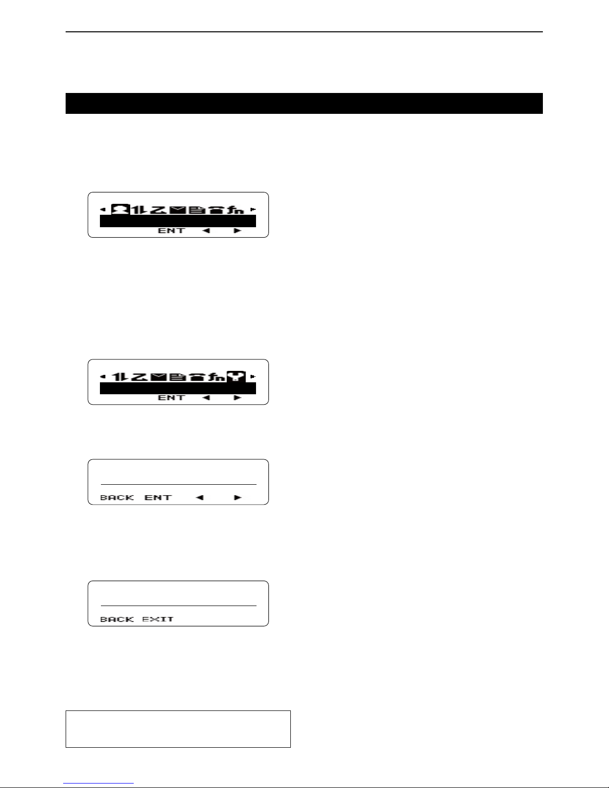
Editing the Autodial list D
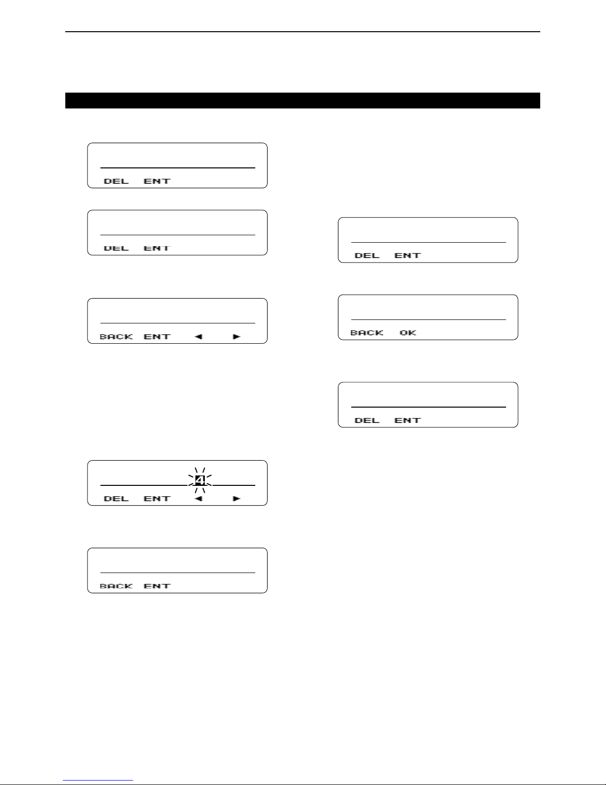
Push [Autodial Programming]. q
AUTDIAL PRGM
AUTODIAL 1
Push [UP] or [DOWN] to select the number you want w
to edit.
Push [P1](ENT). e
• Enters the Name Entry mode.
AUTODIAL 1
Push [UP] or [DOWN] to enter a character, and then r
push [P1](SEL) to set.
• Goes to the next character entry position.
• You can use the 10-keypad keys of the optional DTMF
microphone to enter a character.
Repeat step t r until you enter a name of up to 12
characters.
• Push [P0](DEL) to delete a character.
• Push [P2](Ω) or [P3](≈) left or right to select a charac-
ter.
AUTODIAL 2
Push [P1](ENT) to save. y
• Enters the DTMF Code Entry mode.
11111
Push [UP] or [DOWN] to enter a digit, and then push u
[P1](SEL) to set.
• Goes to the next digit entry position.
• You can use the 10-keypad keys of the optional DTMF
microphone to enter a digit.
Repeat step i u until you enter a DTMF number of up
to 16 digits.
• Push [P0](DEL) to delete a digit.
11112
Push [P1](ENT) to set. o
• “OVERWRITE?” appears.
OVERWRITE?
!0 Push [P1](OK) to overwrite.
• Push [P0](BACK) to return to the DTMF Code Entry
mode.
AUTDIAL PRGM
AUTODIAL 2
Page 21
3
ADVANCED OPERATION
3-4
DTMF Calls (Continued)
Adding an entry to the Autodial list D
Push [Autodial Programming]. q
AUTDIAL PRGM
AUTODIAL 1
Push [UP] or [DOWN] to select a blank number. w
AUTDIAL PRGM
BLANK 04
Push [P1](ENT). e
• Enters the Name Entry mode.
• “NAME?” appears.
NAME?
Push [UP] or [DOWN] to enter a character, and then r
push [P1](SEL) to set.
• Goes to the next character entry position.
• You can use the 10-keypad keys of the optional DTMF
microphone to enter a character.
Repeat step t r until you enter a name of up to 12
characters.
• Push [P0](DEL) to delete a character.
• Push [P2](Ω) or [P3](≈) left or right to select a charac-
ter.
AUTODIAL 4
Push [P1](ENT) to set. y
• Enters the DTMF Code Entry mode.
• “CODE?” appears.
CODE?
Push [UP] or [DOWN] to enter a digit, and then push u
[P1](SEL) to set.
• Goes to the next digit entry position.
• You can use the 10-keypad keys of the optional DTMF
microphone to enter a digit.
Repeat step i u until you enter a DTMF number of up
to 16 digits.
• Push [P0](DEL) to delete a digit.
12345
Push [P1](ENT) to set. o
• “STORE?” appears.
STORE?
!0 Push [P1](OK) to store.
• Push [P0](BACK) to return to the DTMF Code Entry
mode.
AUTDIAL PRGM
AUTODIAL 4
Page 22

3
ADVANCED OPERATION
3-5
Emergency Calls
Emergency Calls D
When [Emergency] is assigned to [R], you can manually make an Emergency call.
Hold down [ q R] for 1 second.
• Enters the Emergency mode.
• When the transceiver enters the Emergency mode, it will
change to the Emergency channel and begin transmitting, according to the presetting.
To exit from the Emergency mode, hold down [ w R]
again, or turn OFF the power.
• If the Emergency mode completes a preset number of
call cycles, the transceiver will automatically exit the
mode and return to the zone and channel that was in use
before you entered the Emergency mode.
Lone Worker Emergency Call D
When the Lone Worker function is activated, the Emergency function is automatically turned ON, after the
preset time period has passed with no operation performed.
Push [Lone Worker] to turn the function ON or OFF. ➥
NOTE:
The Emergency Mode Type can be set to “Silent” or
“Audible” by using the optional cloning software.
When “Audible” is set, the transceiver sounds a beep
when transmitting in the Emergency mode.
[R]
Page 23

3
ADVANCED OPERATION
3-6
Scrambler
The Voice Scrambler function provides private communication between stations. All transceiver versions have
a built-in scrambler.
Push [Scrambler/Encryption] to turn the function ON ➥
or OFF.
• “ ” appears when the Scrambler function is ON.
• After turning ON the function, push [PTT] to make an
encrypted call.
Changing the Scrambler code setting: ✓
Hold down [Scrambler/Encryption Code] to enter the q
Scrambler Code Setting mode.
• The length of time you hold down [Scrambler/Encryption
Code] may differ, depending on the presetting.
Push [UP] or [DOWN] to select a desired code. w
Push [P1](EXIT) to save and exit. e
• Even if the Scrambler function is OFF in step q, it auto-
matically turns ON after exiting the Scrambler Code setting mode.
Page 24

3
ADVANCED OPERATION
3-7
Radio Access Number (RAN)
RAN is a signaling system designed for digital radio
communications.
When a channel is set up with a RAN, the squelch will
open only when a call containing a matching RAN is
received.
If a call containing a different RAN is made on the same
channel you are using, you will not hear the call.
Page 25

4-1
Section 4
SCAN OPERATION
Scan operation .........................................................................4-2
Temporary channel lockout ....................................................4-3
Priority scan .............................................................................4-4
Setting a Priority channel D ........................................................4-4
Scan Revert channel ...............................................................4-5
Scan delete/add .......................................................................4-6
Page 26

4
SCAN OPERATION
4-2
Scan operation
A scan monitors for signals on the transceiver channels.
While scanning, the transceiver checks for a signal on
each channel and stops when a signal is received.
Push [Scan] each time to start or stop a scan. ➥
• “ ” appears while scanning.
• When the transceiver detects a signal, the scan pauses
on the channel. The transceiver remains on the busy
channel until the signal disappears, and then the scan
resumes.
SCAN
While scanning
NOTE: Two or more channels must be programmed
to start a scan.
For your reference:
Before starting a scan, set the following items:
• Set 3 scan types in the transceiver: Single, Multi or
List.
• Set the scan type in both the conventional and trunking zones.
• Set Priority channels, but only in conventional type
zones.
When you select a conventional zone, trunking zones
are not scanned.
When you select a trunking zone, conventional zones
are not scanned.
Select the desired zone to start scanning.
• Single: The transceiver scans the preset target
channels or GIDs in only the selected zone.
For a Priority scan, all Priority channels will
also be scanned, even if they are in other
conventional type zones.
• Multi: The transceiver scans the preset target
channels or GIDs in only the preset target
zones.
For a Priority scan, all Priority channels will
also be scanned, even if they are in other
conventional type zones.
• List: The transceiver scans the preset target
channels or GIDs in only the zones that are
preset on the Scan List.
For a Priority scan, all Priority channels will
also be scanned, even if they are in conventional type zones that are not on the List.
NOTE:
When the scan starts in the Conventional group zone,
the NXDN Trunking system zone is not scanned.
When the scan starts in the NXDN Trunking system
zone, the Conventional group zone is not scanned.
Page 27

4
SCAN OPERATION
4-3
Temporary channel lockout
During a scan, you can temporarily delete a channel
from a scanning sequence.
This function speeds up scanning by skipping unwanted channels.
Start the scan. (p. 4-2) q
• When a signal is received, the scan pauses.
While the scan is paused, and if you want to skip the w
frequency, push [Scan Delete/Add].
• “Ú” (scan target channel icon) disappears when the se-
lected channel is deleted from the scanning sequence.
• The channel is no longer scanned. However, depending
on the presetting, the deleted channel may be added to
the scan group again after the scan is cancelled.
See also: “Scan delete/add” on page 4-6
Page 28
4
SCAN OPERATION
4-4
Priority scan
The Priority scan scans all scan target channels or
GIDs in the zone while also monitoring the Priority 1
and Priority 2 channels.
When the scan is paused on the Priority 1 channel, the
other channels are not monitored.
Setting a Priority channel D
Depending on the presetting, you can manually set a
Priority channel (Priority 1, Priority 2 or Priority 1 & 2).
Select a channel that you want to set as a Priority q
channel.
Channel 1
Push [Priority-channel Select]. w
• Enters the Priority Channel Setting mode.
PRI CH SEL
NORMAL
Push [UP] or [DOWN] to select “PRIORITY 1,” e
“PRIORITY 2” or “PRIORITY 1 & 2.”
PRI CH SEL
PRIORITY 1
Push [P1](OK). r
• The selected channel is set as a Priority channel.
NOTE: When “PRIORITY 1 & 2” is selected, the
same channel is set as both Priority 1 and Priority 2
channels.
Page 29

4
SCAN OPERATION
4-5
Scan Revert channel
The Scan Revert channel is automatically selected
when you push [PTT] to make a call during a scan.
The Scan Revert channel can be set to the transceiver
using the optional cloning software.
• Last Called + Selected:
The transceiver makes a call on the last channel
or GID that you received a call on.
However, if you push [PTT] while the scan is
paused, the transceiver makes a call on the channel or to the GID that the scan is paused on.
When you change the channel or GID before
starting a scan, the transceiver makes a call on
the selected channel or to the GID until the transceiver receives another call.
• Selected:
The transceiver makes a call on the channel or to
the GID selected before a scan.
• Selected + Talkback:
The transceiver makes a call on the channel or to
the GID selected before a scan.
However, if you push [PTT] when the scan is
paused, the transceiver makes a call on the channel or to the GID that the scan is paused on.
• Priority 1:
The transceiver makes a call on the Priority 1
channel.
• Priority 1 + Talkback:
The transceiver makes a call on the Priority 1
channel.
However, if you push [PTT] when the scan is
paused, the transceiver makes a call on the channel or to the GID that the scan is paused on.
• Priority 2:
The transceiver makes a call on the Priority 2
channel.
• Priority 2 + Talkback:
The transceiver makes a call on the Priority 2
channel.
However, if you push [PTT] when the scan is
paused, the transceiver makes a call on the channel or to the GID that the scan is paused on.
Page 30

4
SCAN OPERATION
4-6
Scan delete/add
During scan, you can temporarily delete a channel or
zone from the scanning sequence.
Select a channel, GID or zone that you want to de- q
lete from the sequence.
Push [Scan Delete/Add]. w
• “Ú” disappears when the selected channel, GID or zone
is deleted from the scanning sequence.
Channel 1
To manually add a channel, GID or zone to the scanning sequence, repeat steps q and w.
• “Ú” appears when the selected channel is added to the
sequence.
Page 31

5-1
Section 5
MENU SCREEN
Menu screen description ........................................................5-2
Entering the Menu screen D .......................................................5-2
Menu functions ........................................................................5-3
Page 32
5
MENU SCREEN
5-2
Menu screen description
When [Menu] is assigned, you can open the Menu
screen.
In the Menu screen, the items are categorized.
Depending on the presetting, you can select various
functions and adjust the transceiver settings in the
Menu screen.
CONTACT
Menu screen (Sample)
Entering the Menu screen D
Example: Setting the squelch level
Push [MENU]. q
• Opens the Menu screen.
Push [P2]( w Ω) or [P3](≈) to select the category that
has the “SQL LEVEL” item. (Default: “UTILITY”)
UTILITY
Push [P1](ENT). e
• Enters the Menu Item Select mode.
Push [P2]( r Ω) or [P3](≈) to select the “SQL LEVEL”
item.
UTILITY
SQL LEVEL
Push [P1](ENT). t
• Enters the Squelch Level Adjustment mode.
Push [UP] to increase the squelch level up to 9 (tight y
squelch), or push [DOWN] to decrease the squelch
level down to 0 (loose squelch).
• Push [P0](BACK) to return to the previous screen.
LEVEL 9
After setting, push [P1](EXIT). u
• Closes the Menu screen.
For your reference:
You can close the Menu screen by pushing [R], even
if an item is selected.
Page 33

5
MENU SCREEN
5-3
Menu functions
Autodial “AUTO DIAL”
Opens the DTMF Autodial code selection screen.
When “AUTO DIAL” is displayed, push [P1](ENT). q
• The rst entry in the Autodial list appears.
Push [UP] or [DOWN] to select a desired number. w
Push [P3](TX) to send. e
When the Store & Send function is enabled:
When “AUTO DIAL” is displayed, push [P1](ENT). q
• “CODE?” appears.
Push [UP] or [DOWN] to enter a digit, and then push w
[P1](SEL) to set.
• Goes to the next digit entry position.
• You can use the 10-keypad keys on the optional DTMF
microphone.
Repeat step e w until you enter up to 30 digits.
• Push [P0](DEL) to delete the entered digit.
• Push [P1](EXIT) to exit the DTMF Code Entry mode.
• Push [P2](MODE) to toggle between the DTMF Code En-
try mode and the DTMF Autodial code selection mode.
Push [P3](TX) to send. r
Autodial Programming “AUTDIAL PRGM”
Enters the DTMF Code Programming mode.
When “AUTDIAL PRGM” is displayed, push [P1](ENT). q
• The rst entry in the Autodial list appears.
Push [UP] or [DOWN] to select a desired number. w
Push [P1](ENT). e
• Enters the Name Entry mode. (p. 3-3)
AUX A “AUX A”
Turns the AUX A port ON or OFF.
When “ q
AUX A
” is displayed, push [P1](ENT).
Push [UP] or [DOWN] to select ON or OFF. w
• Push [P0](BACK) to return to the previous screen.
Push [P1](OK) to save. e
AUX B “AUX B”
Turns the AUX B port ON or OFF.
When “ q
AUX B
” is displayed, push [P1](ENT).
Push [UP] or [DOWN] to select ON or OFF. w
• Push [P0](BACK) to return to the previous screen.
Push [P1](OK) to save. e
Broadcast “BROADCAST”
❍
In the NXDN Trunking system
Turns the Broadcast Call ON or OFF.
This item can also be used to make a Broadcast Group
Call.
When “BROADCAST” is displayed, push [P1](ENT). q
Push [UP] or [DOWN] to select ON or OFF. w
• Push [P0](BACK) to return to the previous screen.
Push [P1](OK) to save. e
When “ON” is selected in step w, push [PTT] to send
the Broadcast Group Call.
Direct CH/GID 1 Select to Direct CH/GID 5 Select
“DIRECT CHGD1” to “DIRECT CHGD5”
Sets the selected channel or GID to a Direct CH/GID
between 1 and 5.
Select a desired channel. (p. 2-4) q
Push [MENU]. w
• Opens the Menu screen.
When a channel between “DIRECT CHGD1” and e
“DIRECT CHGD5” is displayed, push [P1](ENT).
• Sets the selected channel to a Direct channel between 1
and 5.
Display Format “DISP FORMAT”
❍ In the Analog mode or
NXDN Conventional system
Toggles the display format between the channel name
and the zone and channel number.
❍
In the NXDN Trunking system
Toggles the display format between the GID name and
the GID number.
When “DISP FORMAT” is displayed, push [P1] q
(ENT).
Push [UP] or [DOWN] to select “CH NAME” or w
“ZONE-CH No.”
• Push [P0](BACK) to return to the previous screen.
Push [P1](OK) to save. e
External Speaker “
EXT SPEAKER
”
Turns the External speaker function ON or OFF.
When the External speaker function is ON, the PA
speaker that is connected to the D-Sub 15-pin will enabled.
• In this case, the front panel speaker and the speaker that is
connected to the external speaker jack will be disabled.
When “EXT SPEAKER” is displayed, push [P1](ENT). q
Push [UP] or [DOWN] to select ON or OFF. w
• Push [P0](BACK) to return to the previous screen.
Push [P1](OK) to save. e
Page 34

5
MENU SCREEN
5-4
Menu functions (Continued)
Fixed Volume “FIXED VOLUME”
Toggles the tone level between “High” and “Low,” or
turns OFF the tone.
When “FIXED VOLUME” is displayed, push [P1] q
(ENT).
Push [UP] or [DOWN] to select “LOW,” “HIGH” or w
“OFF.”
• Push [P0](BACK) to return to the previous screen.
Push [P1](OK) to save. e
Forced Search “FORCE SEARCH”
❍
In the NXDN Trunking system
Starts to search for a site.
When “FORCE SEARCH” is displayed, push [P1] ➥
(ENT).
• Displays “SEARCHING.”
GPS Position Display “GPS POS DISP”
Enters the GPS Position Display mode.
In the GPS Position Display mode, you can check your
latitude and longitude position.
When “GPS POS DISP” is displayed, push [P1] q
(ENT).
• You can check your latitude and longitude position.
Push [UP] or [DOWN] to toggle between the latitude w
and longitude position display.
• Push [P0](BACK) to return to the previous screen.
• Push [P1](EXIT) to the GPS Position Display mode.
• Push [P2](DISP) to automatically switch the latitude and
longitude position display.
Group (NXDN) “GROUP MODE”
❍ In the NXDN Conventional system or
the NXDN Trunking system
Enters the Group Call mode.
In the NXDN Conventional system, this function is used
for Group Calls.
In the NXDN Trunking system, the Group ID List is displayed, but the transceiver cannot make Group calls.
When “GROUP MODE” is displayed, push [P1] q
(ENT).
Push [UP] or [DOWN] to select a desired GID. w
Push [PTT] to call the selected GID. e
Group + SDM (NXDN) “GROUP+SDM”
❍ In the NXDN Conventional system or
the NXDN Trunking system
Enters the Group Call mode, and then the Short Data
Message Entry mode.
When “GROUP+SDM” is displayed, push [P1](ENT). q
Push [UP] or [DOWN] to select a desired GID. w
Push [P1](ENT). e
• Enters the Short Data Message Entry mode.
Push [UP] or [DOWN] to enter a character, and then r
push [P1](SET) to set.
• Goes to the next character entry position.
• You can use the 10-keypad keys on the optional DTMF
microphone.
Repeat step t r until you enter a message of up to
100 characters.
• Push [P0](DEL) to delete a character.
• Push [P2](Ω) or [P3](≈) left or right to select a charac-
ter.
Push [PTT] to send the message to the selected y
GID.
Group + Status (NXDN) “GROUP+STATUS”
❍ In the NXDN Conventional system or
the NXDN Trunking system
Enters the Group Call mode, and then the Status Message Entry mode.
When “GROUP+STATUS” is displayed, push [P1] q
(ENT).
Push [UP] or [DOWN] to select a desired GID, and w
then push [P1](ENT).
• Enters the Status Message Selection mode.
Push [UP] or [DOWN] to select the status message e
that you want to send.
• If you want to directly enter a status message, push [P2]
(MODE) to select the Status Message Entry mode.
You can enter a status message between 1 and 207.
• You can use the 10-keypad keys on the optional DTMF
microphone.
Push [P3](TX) to send the message to the selected r
GID.
Page 35

5
MENU SCREEN
5-5
Menu functions (Continued)
High Transmit Power “HI TX POWER”
❍ In the NXDN Trunking system
Toggles the transmit power level.
When “Auto” is set as the default:
When “HI TX POWER” is displayed, push [P1] q
(ENT).
Push [UP] or [DOWN] to select ON (High) or OFF w
(Auto).
• Push [P0](BACK) to return to the previous screen.
Push [P1](OK) to save. e
When “Low” is set as the default:
When “HI TX POWER” is displayed, push [P1] q
(ENT).
Push [UP] or [DOWN] to select ON (High) or OFF w
(Low).
• Push [P0](BACK) to return to the previous screen.
Push [P1](OK) to save. e
See page 5-6 about [Low Transmit Power].
Home CH/GID Select “HOME CHANNEL”
Sets the selected channel or GID as the Home Channel.
Select a desired channel. (p. 2-4) q
Push [MENU]. w
• Opens the Menu screen.
When “HOME CHANNEL” is displayed, push [P1] e
(ENT).
• Sets the selected channel or GID as the Home Channel.
Horn Alert “HORN ALERT”
Turns the Horn Alert function ON or OFF.
When this function is ON, the horn alert port will be activated for a preset time period after receiving a call.
When “ q
HORN ALERT
” is displayed, push [P1](ENT).
Push [UP] or [DOWN] to select ON or OFF. w
• Push [P0](BACK) to return to the previous screen.
Push [P1](OK) to save. e
Individual (NXDN) “INDIVIDUAL”
Enters the Individual Call mode.
When “INDIVIDUAL” is displayed, push [P1](ENT). q
Push [UP] or [DOWN] to select a desired unit ID. w
• If you want to directly enter an unit ID, push [P2](MODE)
to select the Unit ID Entry mode.
You can enter an unit ID between 1 and 65519.
Push [P3](TX) to call to the selected unit ID. e
Individual + SDM (NXDN) “INDIV+SDM”
Enters the Individual Call mode, and then the Short
Data Message Entry mode.
When “INDIV+SDM” is displayed, push [P1](ENT). q
Push [UP] or [DOWN] to select a desired unit ID. w
• If you want to directly enter an unit ID, push [P2](MODE)
to select the Unit ID Entry mode.
You can enter an unit ID between 1 and 65519.
Push [P1](ENT). e
• Enters the Short Data Message Entry mode.
Push [UP] or [DOWN] to enter a character, and then r
push [P1](SET) to set.
• Goes to the next character entry position.
• You can use the 10-keypad keys on the optional DTMF
microphone.
Repeat step t r until you enter a message of up to
100 characters.
• Push [P0](DEL) to delete a character.
• Push [P2](Ω) or [P3](≈) left or right to select a charac-
ter.
Push [PTT] to send the message to the selected unit y
ID.
Individual + Status (NXDN) “INDIV+STATUS”
Enters the Individual Call mode, and then the Status
Message Entry mode.
When “INDIV+STATUS” is displayed, push [P1](ENT). q
Push [UP] or [DOWN] to select a desired unit ID. w
• If you want to directly enter an unit ID, push [P2](MODE)
to select the Unit ID Entry mode.
You can enter an unit ID between 1 and 65519.
Push [P1](ENT). e
• Enters the Status Message Selection mode.
Push [UP] or [DOWN] to select a status message e
that you want to send.
• If you want to directly enter a status message, push [P2]
(MODE) to select the Status Message Entry mode.
You can enter a status message between 1 and 207.
• You can use the 10-keypad keys on the optional DTMF
microphone.
Push [P3](TX) to send the message to the selected r
unit ID.
LCD Brightness “LCD BRIGHT”
Selects the brightness of the function display and keys
backlight.
Select High, Low or OFF to meet your needs.
The function display and keys can be backlit for better
visibility under low light conditions.
When “LCD BRIGHT” is displayed, push [P1](ENT). q
Push [UP] or [DOWN] to select “LOW,” “HIGH” or w
“OFF.”
• Push [P0](BACK) to return to the previous screen.
Push [P1](OK) to save. e
Page 36

5
MENU SCREEN
5-6
Menu functions (Continued)
Lone Worker “LONE WORKER”
Turns the Lone Worker function ON or OFF. (p. 3-5)
When “LONE WORKER” is displayed, push [P1] q
(ENT).
Push [UP] or [DOWN] to select ON or OFF. w
• Push [P0](BACK) to return to the previous screen.
Push [P1](OK) to save. e
Low Transmit Power “LOW TX POWER”
❍ In the Analog mode or
NXDN Conventional system
Toggles the transmit power between “High” and “Low,” if
“High” is set as the default.
When “LOW TX POWER” is displayed, push [P1] q
(ENT).
Push [UP] or [DOWN] to select ON (Low) or OFF w
(High).
• Push [P0](BACK) to return to the previous screen.
Push [P1](OK) to save. e
❍
In the NXDN Trunking system
Toggles the transmit power level.
When the transmit power level is set to “Auto” as the
default:
When “LOW TX POWER” is displayed, push [P1] q
(ENT).
Push [UP] or [DOWN] to select ON (Low) or OFF w
(Auto).
• Push [P0](BACK) to return to the previous screen.
Push [P1](OK) to save. e
When the transmit power level is set to “High” as the
default:
When “LOW TX POWER” is displayed, push [P1] q
(ENT).
Push [UP] or [DOWN] to select ON (Low) or OFF w
(High).
• Push [P0](BACK) to return to the previous screen.
Push [P1](OK) to save. e
See page 5-5 about [High Transmit Power].
Maintenance “MAINTENANCE”
Enters the Maintenance Display mode.
In the Maintenance Display mode, you can check the
RSSI level of the selected channel for installation or
maintenance of the system.
When “MAINTENANCE” is displayed, push [P1](ENT). q
• Displays the RSSI level.
• Push [P0](BACK) to return to the previous screen.
Push [P1](EXIT) to exit. w
Monitor “MONITOR”
❍ In the Analog mode
Turns the Monitor ON or OFF.
When the Monitor is ON, the transceiver releases the
CTCSS mute.
❍ In the NXDN Conventional system
Turns the Monitor ON or OFF.
When the Monitor is ON, the transceiver releases the
RAN code mute.
When “MONITOR” is displayed, push [P1](ENT). q
Push [UP] or [DOWN] to select ON or OFF. w
• Push [P0](BACK) to return to the previous screen.
Push [P1](OK) to save. e
Operator Selectable Tone “OST”
Turns the OST (Operator Selectable Tone) mode ON
or OFF.
When the OST mode is ON, the selected tone in the
OST list is enabled.
When “OST” is displayed, push [P1](ENT). q
Push [UP] or [DOWN] to select ON or OFF. w
• Push [P0](BACK) to return to the previous screen.
Push [P1](OK) to save. e
OST List “OST LIST”
Displays the OST (Operator Selectable Tone) list.
When “OST LIST” is displayed, push [P1](ENT). q
Push [UP] or [DOWN] to select a desired OST tone w
or turn OFF the OST tone.
• Push [P0](BACK) to return to the previous screen.
Push [P1](EXIT) to exit. e
Priority-channel Select “PRI CH SEL”
Enters the Priority Channel Select mode for a Priority
scan.
Select a desired channel. (p. 2-4) q
Push [MENU]. w
• Opens the Menu screen.
When “PRI CH SEL” is displayed, push [P1](ENT). e
Push [UP] or [DOWN] to select “PRIORITY 1,” “PRI- r
ORITY 2,” “PRIORITY 1 & 2” or “NORMAL.”
• Push [P0](BACK) to return to the previous screen.
Push [P1](OK). t
• Sets the selected channel to Priority 1, Priority 2, Priority
1 and 2 or a Normal channel.
NOTE: When “PRIORITY 1 & 2” is selected, the
same channel is set as both Priority 1 and Priority 2
channels.
Page 37

5
MENU SCREEN
5-7
Menu functions (Continued)
Public Address “PUB ADDRESS”
Turns the Public Address function ON or OFF.
When this function is ON, you can make announcements through a PA speaker.
• Transmitting is disabled while in the PA mode.
When “PUB ADDRESS” is displayed, push [P1] q
(ENT).
Push [UP] or [DOWN] to select ON or OFF. w
• Push [P0](BACK) to return to the previous screen.
Push [P1](OK) to save. e
RX Audio Equalizer “RX AUDIO EQ”
This function sets the audio characteristics type to apply to the received audio.
When “RX AUDIO EQ” is displayed, push [P1] q
(ENT).
Push [UP] or [DOWN] to select the option. w
• Push [P0](BACK) to return to the previous screen.
• FLAT:
Selects the standard audio characteristics.
• HIGH BOOST:
Emphasizes the treble range.
• LOW BOOST:
Suppresses the treble range and boosts the
bass range.
Push [P1](EXIT) to save. e
RX Auto Gain Control “RX AUTO GAIN”
This function automatically adjusts the received audio
volume to an appropriate level so that you can clearly
hear the audio.
When “RX AUTO GAIN” is displayed, push [P1] q
(ENT).
Push [UP] or [DOWN] to select the option. w
• Push [P0](BACK) to return to the previous screen.
• OFF: Disables the Auto Gain Control. The received
audio level is only adjusted by [VOL].
• HIGH: Enables the Auto Gain Control. The received
audio level will be automatically adjusted to
an appropriate constant level, according to
the [VOL] setting. However, the background
noise will be boosted, and howling may occur, depending on your operating environment.
• LOW: Enables the Auto Gain Control. The received
audio level will be automatically adjusted to
an appropriate constant level, according
to the [VOL] setting. However, the adjustable gain is smaller than the “HIGH” setting.
Therefore, background noise boosting will
also be smaller, and howling may not occur.
Push [P1](EXIT) to save. e
RX Low Cut “RX LOW CUT”
While receiving a digital signal, this function cuts the
frequency components at 300 Hz or below.
When “RX LOW CUT” is displayed, push [P1](ENT). q
Push [UP] or [DOWN] to select ON or OFF. w
• Push [P0](BACK) to return to the previous screen.
Push [P1](EXIT) to save. e
Scan “SCAN”
Starts or stops a scan.
When “SCAN” is displayed, push [P1](ENT). q
Push [UP] or [DOWN] to select ON or OFF. w
• Push [P0](BACK) to return to the previous screen.
Push [P1](OK). e
• A scan starts when “ON” is selected in step w.
• A scan stops when “OFF” is selected in step w.
Scan Delete/Add “SCAN DEL/ADD”
Sets or cancels the selected channel or GID as the
scan target.
Select a desired channel. (p. 2-4) q
Push [MENU]. w
• Opens the Menu screen.
When “SCAN DEL/ADD” is displayed, push [P1] e
(ENT).
Push [UP] or [DOWN] to select “DELETE” or “ADD.” r
• Push [P0](BACK) to return to the previous screen.
Push [P1](OK). t
• The selected channel is canceled as a scan target when
“DELETE” is selected in step r.
• The selected channel is set as a scan target when “ADD”
is selected in step r.
Scrambler/Encryption “SCRAM/ENCRYP”
❍ In the Analog mode
Turns the Scrambler function ON or OFF.
❍ In the NXDN Conventional system or
the NXDN Trunking system
Turns the Encryption function ON or OFF.
When “SCRAM/ENCRYP” is displayed, push [P1] q
(ENT).
Push [UP] or [DOWN] to select ON or OFF. w
• Push [P0](BACK) to return to the previous screen.
Push [P1](OK) to save. e
Page 38

5
MENU SCREEN
5-8
Menu functions (Continued)
Scrambler/Encryption Code “SCRAM CODE”
❍ In the Analog mode
Enters the Scrambler Code Selection mode.
❍ In the NXDN Conventional system or
the NXDN Trunking system
Enters the Encryption Key Selection mode.
When “SCRAM CODE” is displayed, push [P1] q
(ENT).
• The Scrambler or the Encryption function automatically
turns ON.
Push [UP] or [DOWN] to select a desired Scrambler w
code or Encryption key.
• Push [P0](BACK) to return to the previous screen.
Push [P1](EXIT) to save. e
SDM (NXDN) “SHRT MSG MOD”
❍ In the NXDN Conventional system or
the NXDN Trunking system
Directly enters the Short Message mode.
When “SHRT MSG MOD” is displayed, push [P1] q
(ENT).
• “MESSAGE?” appears.
Push [UP] or [DOWN] to enter a character, and then w
push [P1](SEL) to set.
• Goes to the next character entry position.
• You can use the 10-keypad keys on the optional DTMF
microphone.
Repeat step e w until you enter a message of up to
100 characters.
• Push [P0](DEL) to delete a character.
• Push [P2](Ω) or [P3](≈) left or right to select a charac-
ter.
Push [PTT] to send the message to the Base ID. r
Push [P1](EXIT) to exit. t
Send the GPS Data “SND GPS DATA”
❍ In the NXDN Conventional system or
the NXDN Trunking system
Sends the position data that is received from the GPS
receiver to a Base station.
When “SND GPS DATA” is displayed, push [P1](ENT). q
Push [P1](ENT) to send. w
Site Lock “SITE LOCK”
❍ In the NXDN Trunking system
Turns the Site Lock function ON or OFF.
When “SITE LOCK” is displayed, push [P1](ENT). q
Push [UP] or [DOWN] to select ON or OFF. w
• Push [P0](BACK) to return to the previous screen.
Push [P1](OK) to save. e
Site Number “SITE No.”
❍ In the NXDN Trunking system
Display the current Site number.
When “SITE No.” is displayed, push [P1](ENT). ➥
• Displays the current Site number for 3 seconds, and then
exits the Menu screen.
Site Select “SITE”
❍ In the NXDN Trunking system
Enters the Site Select mode.
When “SITE” is displayed, push [P1](ENT). q
Push [UP] or [DOWN] to select a desired site. w
• Push [P0](BACK) to return to the previous screen.
Push [P1](SEL) to save. e
Squelch Level “SQL LEVEL”
❍ In the Analog mode
Enters the Squelch Level Adjustment mode.
When “SQL LEVEL” is displayed, push [P1](ENT). q
Push [DOWN] to decrease the squelch level down w
to 0 (loose squelch), or push [UP] to increase the
squelch level up to 9 (tight squelch).
• Push [P0](BACK) to return to the previous screen.
Push [P1](EXIT) to exit. e
Squelch Off “SQL OFF”
❍ In the Analog mode or
the NXDN Conventional system
Opens the squelch, and releases the mute.
When “SQL OFF” is displayed, push [P1](ENT). q
Push [UP] or [DOWN] to select ON or OFF. w
• Push [P0](BACK) to return to the previous screen.
Push [P1](OK) to exit. e
Stack “STACK”
Enters the Memory Stack mode.
When “STACK” is displayed, push [P1](ENT). q
• Push [P0](BACK) to return to the previous screen.
Push [UP] or [DOWN] to select a desired message. w
• Push [P0](DEL) to delete the selected message.
• Push [P2](DISP) to change the display item between re-
ceived ID, message contents and channel number.
Push [P1](EXIT) to exit. e
Page 39

5
MENU SCREEN
5-9
Menu functions (Continued)
Status (NXDN) “STATUS”
Directly enters the Status Message mode.
When “STATUS” is displayed, push [P1](ENT). q
Push [UP] or [DOWN] to select a status message. w
• If you want to directly enter a status message, push [P2]
(MODE) to select the Status Message Entry mode.
You can enter a status message between 1 and 207.
• You can use the 10-keypad keys on the optional DTMF
microphone.
Push [P3](TX) to send the message to the Base ID. e
Push [P1](EXIT) to exit. r
Talk Around “TALK AROUND”
❍ In the Analog mode
Turns the talk around function ON or OFF.
When “TALK AROUND” is displayed, push [P1] q
(ENT).
Push [UP] or [DOWN] to select ON or OFF. w
Push [P1](OK) to save. e
Transceiver Password “PASSWORD”
Enters the Password Entry mode.
The transceiver cannot be used until you enter a correct password.
When “PASSWORD” is displayed, push [P1](ENT). q
• Enters the Password Entry mode.
Push [UP] or [DOWN] to enter a digit code, and w then
push [P1] to set.
• Goes to the next digit entry position.
Repeat step e w until you enter the password, and
then push [P1].
When using the DTMF microphone:
Push the [0] to [9] digit keys on the microphone to enter
the password, and then push [#].
NOTE: If “PASSWORD” does not disappear after
pushing [P1], the password code you entered may
be incorrect. In this case, enter the correct password.
TX Audio Equalizer “TX AUDIO EQ”
This function sets the audio characteristics type to apply to the transmit audio.
When “TX AUDIO EQ” is displayed, push [P1](ENT). q
Push [UP] or [DOWN] to select the option. w
• Push [P0](BACK) to return to the previous screen.
• FLAT:
Selects the standard audio characteristics.
• HIGH BOOST:
Selects the audio characteristics emphasizing
the treble range.
• LOW BOOST:
Suppresses the treble range and boosts the
bass range.
Push [P1](EXIT) to save. e
TX Auto Gain Control “TX AUTO GAIN”
This function automatically adjusts the transmit audio
level to an appropriate constant level so that the called
station can hear the audio clearly.
When “TX AUTO GAIN” is displayed, push [P1](ENT). q
Push [UP] or [DOWN] to select ON or OFF. w
• Push [P0](BACK) to return to the previous screen.
• ON: Enables the Auto Gain Control. The transmit
audio level will be adjusted to an appropriate
constant level.
• OFF: Disables the Auto Gain Control.
Push [P1](EXIT) to save. e
TX Noise Suppressor “TX NOISE SUP”
This function enables transmitting while in the digital
mode and reducing or eliminating the noise component
in the background noise.
When “TX NOISE SUP” is displayed, push [P1] q
(ENT).
Push [UP] or [DOWN] to select ON or OFF. w
• Push [P0](BACK) to return to the previous screen.
Push [P1](EXIT) to save. e
Zone Delete/Add “ZONE DEL/ADD”
Sets or cancels the selected zone as a scan target.
Select a desired zone. (p. 2-3) q
Push [MENU]. w
• Opens the Menu screen.
When “ZONE DEL/ADD” is displayed, push [P1] e
(ENT).
Push [UP] or [DOWN] to select “DELETE” or “ADD.” r
• Push [P0](BACK) to return to the previous screen.
Push [P1](OK). t
• The selected zone is canceled as a scan target when
“DELETE” is selected in step r.
• The selected zone is set as a scan target when “ADD” is
selected in step r.
Page 40

6-1
Section 6
NXDN OPERATION <COMMON>
NXDN system operation ..........................................................6-2
Memory Stack ..........................................................................6-3
Viewing a stored message D ......................................................6-3
Deleting a desired message D ....................................................6-4
Deleting all stored messages D ..................................................6-4
Page 41

6
NXDN OPERATION <COMMON>
6-2
NXDN system operation
NXDN is a “Common Air Interface” (CAI), the name for
over-the-air methods by which transceivers and repeaters communicate. NXDN defines the next-generation
digital protocol.
The NXDN system has two operating modes, conventional and trunking.
In an NXDN conventional system, you should manually
search for a clear channel.
In an NXDN trunking system, the repeater automatically searches for a clear channel, and sends the information to the transceivers.
In addition, Type-C requires a Control Channel repeater.
If you use an NXDN transceiver, you can transmit and
receive Individual Calls, Group Calls, Status Messages,
Short Messages, and so on.
Page 42

6
NXDN OPERATION <COMMON>
6-3
Memory Stack
The transceiver has a Memory Stack. When the transceiver receives a Status Message or a Short Message,
the received content is stored in the transceiver’s Memory Stack.
If you turn OFF the transceiver’s power, the contents
will be cleared.
The stored messages are displayed using the following
indication.
Information Indication
Message type Caller ID Stack “ID”
Status Message “ST”
Short Message “SM”
Stored number Stored number “01” to “15”
Display items Caller ID “ID”
Message contents “MSG”
Received channel or GID “CH”
Viewing a stored message D
When a transceiver receives data: q
• Displays “DATA RCVD,” “COMPLETE,” the received mes-
sage, the caller’s unit ID and GID*.
*Displays only when the received call is a Group call.
• “
” blinks.
Push [Stack]. w
• Enters the Memory Stack mode.
• Displays “STACK.”
Push [UP] or [DOWN] to select a desired message. e
Push [P2](DISP) to change the displayed item be- r
tween received ID, message contents and channel
number.
STACK
SM01 ID
STACK
UID 0001
Scrolls
STACK
SM01 MSG
STACK
SHORT MESSAG
STACK
SM01 CH
STACK
CH CH01
Received ID
Message contents
Channel number
Push [P1](EXIT). t
• Exits the Memory Stack mode.
Page 43

6
NXDN OPERATION <COMMON>
6-4
Memory Stack (Continued)
Deleting a desired message D
Push [Stack]. q
• Enters the Memory Stack mode.
• Displays “STACK.”
Push [UP] or [DOWN] to select a desired message. w
Push [P0](DEL). e
• Displays “DELETE?.”
Push [P1](OK). r
• Deletes the selected message.
• Push [P0](BACK) to return to the previous screen.
• Push [R] to exit the Memory Stack mode.
Deleting all stored messages D
Push [Stack]. q
• Enters the Memory Stack mode.
• Displays “STACK.”
Hold down [P0](DEL) for 1 second. w
• Displays “ALL DELETE?.”
Push [P1](OK). e
• Deletes all messages.
• Push [P0](BACK) to return to the previous screen.
• Push [R] to exit the Memory Stack mode.
Page 44

7-1
Section 7
NXDN OPERATION <TRUNKING MODE>
NXDN trunking operation ........................................................7-2
Selecting a GID (Group ID) .....................................................7-3
Selecting a GID D ......................................................................7-3
Selecting a Home GID D .............................................................7-3
Directly entering a GID D ............................................................7-3
Transmitting a call ...................................................................7-4
Group call (Transmission Trunked) D ..........................................7-4
Individual call (Transmission Trunked) D .....................................7-5
Group call (Message Trunked) D ................................................7-6
Individual call (Message Trunked) D ...........................................7-6
Broadcast Group call D ...............................................................7-7
Status call D ................................................................................7-7
Short Data call D .........................................................................7-8
Long Data call D .........................................................................7-8
Telephone call D .........................................................................7-9
Receiving a call ........................................................................7-10
Group call D ................................................................................7-10
Individual call D ...........................................................................7-10
Broadcast Group call D ...............................................................7-11
Status call D ................................................................................7-11
Short Data call D .........................................................................7-12
Long Data call D .........................................................................7-12
Telephone call D .........................................................................7-13
Forced Search ..........................................................................7-14
Page 45

7
NXDN OPERATION <TRUNKING MODE>
7-2
NXDN trunking operation
When you select the NXDN Trunking system mode,
your transceiver automatically searches for, and selects a clear channel.
To use the NXDN Trunking system mode, your transceiver must register to a Control Channel repeater.
Before operating in the NXDN Trunking system mode,
select the NXDN Trunking System zone. (p. 2-3)
Page 46
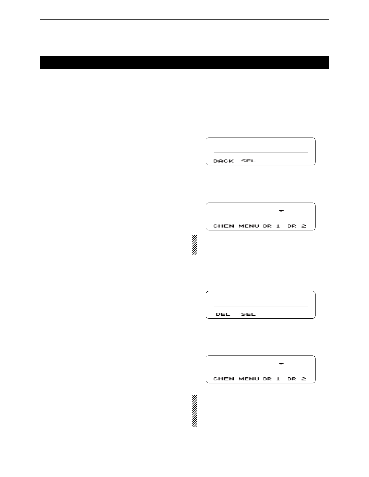
7
NXDN OPERATION <TRUNKING MODE>
7-3
Selecting a GID (Group ID)
Selecting a GID D
To select a desired GID, do one of the following:
Push [CH/GID Up] or [CH/GID Down]. ➥
Push one of the direct GID select keys, [Direct CH/ ➥
GID 1] to [Direct CH/GID 5].
• You can change the GID that is selected by pushing [Direct CH/GID 1] to [Direct CH/GID 5], as described below.
Changing the Direct GID setting:
Select a desired GID. q
Hold down one of the [Direct CH/GID 1] to [Direct w
CH/GID 5] keys for 3 seconds to set the selected
GID to the Direct GID 1 to 5.
Directly entering a GID D
You can select a GID by pushing [UP] or [DOWN], or
the [0] to [9] digit keys on the microphone, after pushing
[Channel Entry].
Or, when the Channel Entry function is assigned to the
keypad, you can select a GID by pushing the [0] to [9]
digit keys.
Push [Channel Entry] to enter the GID Entry mode. q
CH ENTER MOD
CH No. _ _
w
Push [UP] or [DOWN] to select
the GID, and then
push [P1](SEL).
• Push [P0](BACK) to cancel the entry, and return to the
screen that you selected before entering the GID Entry
mode.
GR 1
When the GID name is not programmed, the selected zone and channel number are displayed.
(example: “1- 1”)
When using the DTMF microphone:
Push the [0] to [9] digit keys to enter the GID Entry q
mode.
CH ENTER MOD
CH No. _ 1
Enter the GID number, and then push [#]. w
• Push [M] to delete the entered number.
• Push [M] again to cancel the entry, and return to the
screen that you selected before entering the GID Entry
mode.
GR 1
• When the GID name is not programmed, the se-
lected zone and channel number are displayed.
(example: “1- 1”)
• When less than 9 GIDs are programmed in the zone,
you can select a GID without pushing [#] in step w.
Selecting a Home GID D
The Home GID is the most often-used ID, and you can
preset it into the transceiver.
Push [Home CH/GID]. ➥
• You can change the Home GID, as described below.
Changing the Home GID setting:
Select a desired GID. q
Hold down [Home CH/GID Select] for 3 seconds to w
set the selected GID to the Home GID.
Page 47
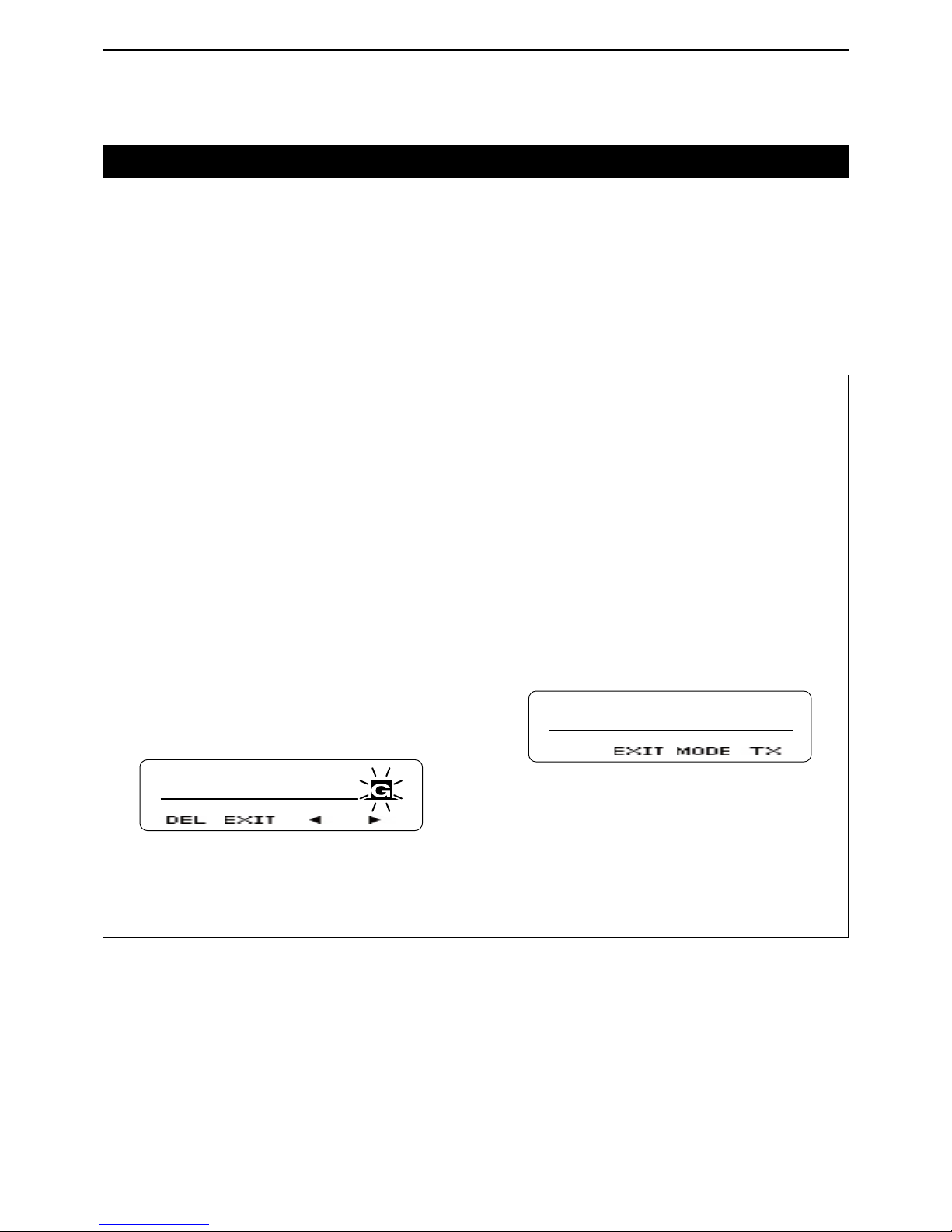
7
NXDN OPERATION <TRUNKING MODE>
7-4
Transmitting a call
Group call (Transmission Trunked) D
When you select an NXDN Trunking System zone and
a desired GID, you can transmit a Group call by simply
pushing [PTT].
When you set GID to “ALL,” you can call all transceivers.
Push [PTT] to make a Group call. ➥
For your reference:
When [Group + SDM (NXDN)] or [Group + Status
(NXDN)] is assigned, you can also send a message
along with a Group call.
To send a Short Data Message along with a Group
call.
Push [Group + SDM (NXDN)] to enter the GID Se- q
lect mode.
• Displays “SELCALL.”
Push [UP] or [DOWN] to select a desired GID. w
Push [P1](ENT). e
• Enters the Short Data Message Entry mode.
Push [UP] or [DOWN] to enter a character, and then r
push [P1](SET) to set.
• Goes to the next character entry position.
• You can use the 10-keypad keys on the microphone.
Repeat step t r until you enter a message of up to
100 characters.
• Push [P0](DEL) to delete a character.
• Push [P2](Ω) or [P3](≈) left or right to select a charac-
ter.
SHORT MESSAG
Push [PTT] to send the message to the selected y
GID.
Push [P1](EXIT) to exit. u
To send a Status Message with a Group call.
Push [Group + Status (NXDN)] to enter the GID Se- q
lect mode.
• Displays “SELCALL.”
Push [UP] or [DOWN] to select a desired GID. w
Push [P1](ENT). e
• Enters the Status Message Entry mode.
Push [UP] or [DOWN] to select a desired status r
message.
• If you want to directly enter a status message, push [P2]
(MODE) to select the Status Message Entry mode.
You can enter a status message between 1 and 207.
• You can use the 10-keypad keys on the microphone.
STATUS
STATUS 001
Push [P3](TX) or [PTT] to send the message to the t
selected GID.
Push [P1](EXIT) to exit. y
Page 48
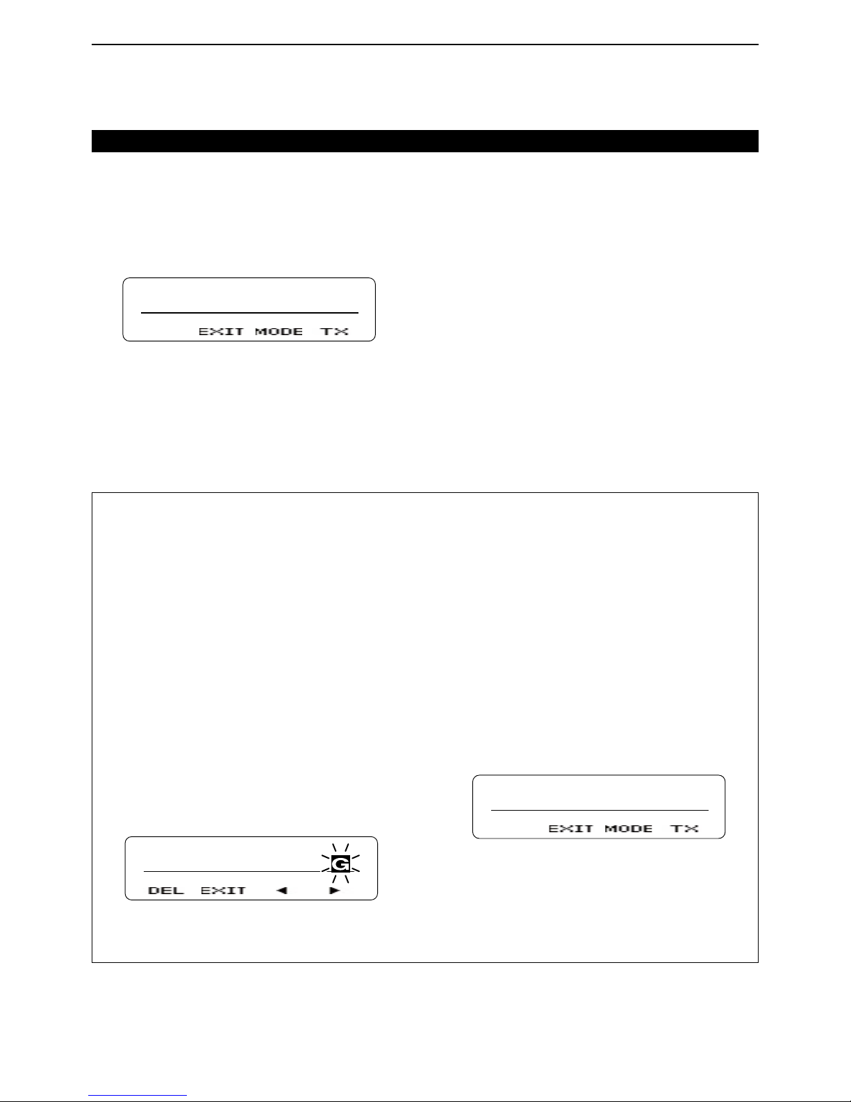
7
NXDN OPERATION <TRUNKING MODE>
7-5
Transmitting a call (Continued)
Individual call (Transmission Trunked) D
You can call a specified station that is set to the same
unit ID by using the Individual call function.
Push [Individual (NXDN)] to enter the Unit ID Select q
mode.
• Displays “SELCALL.”
SELCALL
UID 0001
Push [UP] or [DOWN] to select a desired unit ID. w
• If you want to directly enter an unit ID, push [P2](MODE)
to select the Unit ID Entry mode.
You can enter an unit ID between 1 and 65519.
Push [P3](TX) or [PTT] to make an Individual call. e
Push [P1](EXIT) to exit. r
For your reference:
When [Individual + SDM (NXDN)] or [Individual + Status (NXDN)] is assigned, you can also send a message along with an Individual call.
To send a Short Data Message along with an Individual call.
Push [Individual + SDM (NXDN)] to enter the unit ID q
Select mode.
• Displays “SELCALL.”
Push [UP] or [DOWN] to select a desired unit ID. w
Push [P1](ENT). e
• Enters the Short Data Message Entry mode.
Push [UP] or [DOWN] to enter a character, and then r
push [P1](SET) to set.
• Goes to the next character entry position.
• You can use the 10-keypad keys on the microphone.
Repeat step t r until you enter a message of up to
100 characters.
• Push [P0](DEL) to delete a character.
• Push [P2](Ω) or [P3](≈) left or right to select a charac-
ter.
SHORT MESSAG
Push [PTT] to send the message to the selected y
unit ID.
Push [P1](EXIT) to exit. u
To send a Status Message with an Individual call.
Push [Individual + Status (NXDN)] to enter the unit q
ID Select mode.
• Displays “SELCALL.”
Push [UP] or [DOWN] to select a desired unit ID. w
Push [P1](ENT). e
• Enters the Status Message Entry mode.
Push [UP] or [DOWN] to select a desired status r
message.
• If you want to directly enter a status message, push [P2]
(MODE) to select the Status Message Entry mode.
You can enter a status message between 1 and 207.
• You can use the 10-keypad keys on the microphone.
STATUS
STATUS 001
Push [P3](TX) or [PTT] to send the message to the t
selected unit ID.
Push [P1](EXIT) to exit. y
Page 49
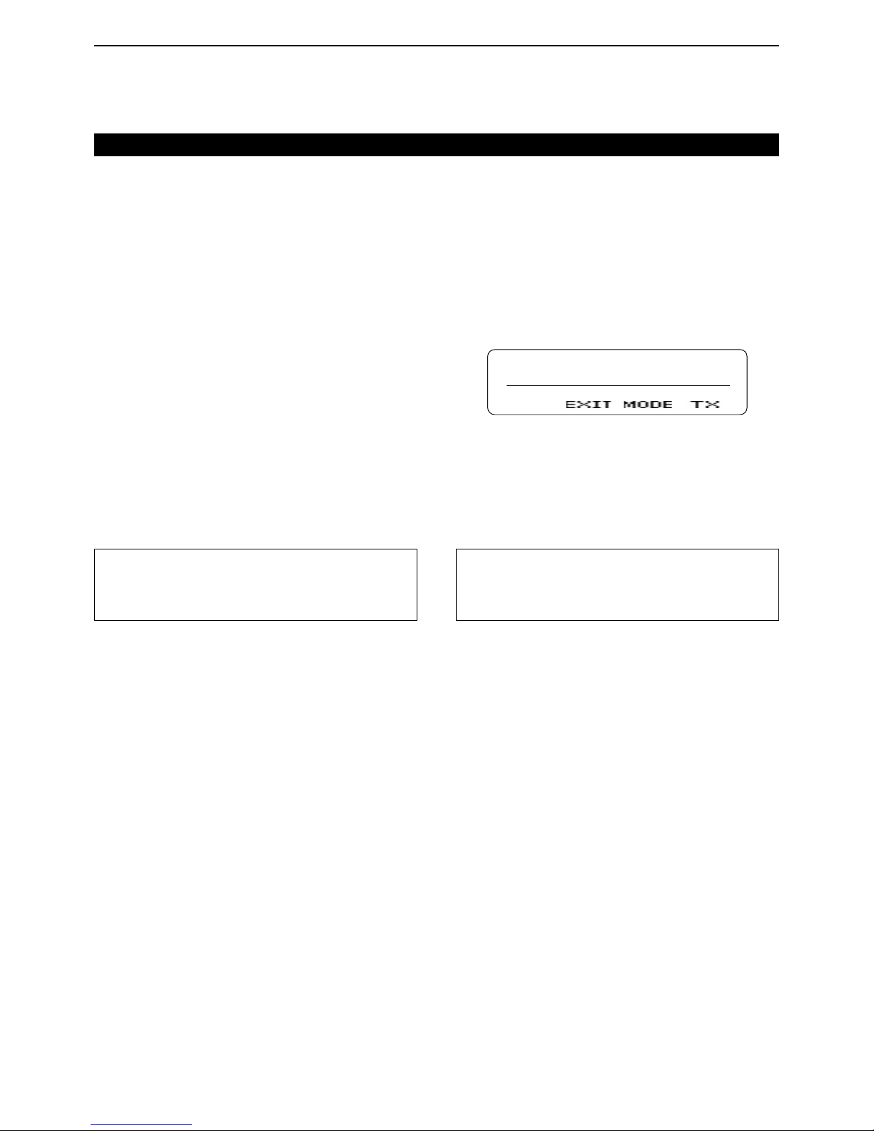
7
NXDN OPERATION <TRUNKING MODE>
7-6
Individual call (Message Trunked) D
When the Trunking type is set to “Message Trunked,”
and after making an Individual call, the transceiver continues to be linked to the traffic channel for a preset
time period.
While linked, the transceivers occupy the traffic channel, and you can call by simply pushing [PTT].
Push [Individual (NXDN)] to enter the Unit ID Select q
mode.
• Displays “SELCALL.”
SELCALL
UID 0001
Push [UP] or [DOWN] to select the desired unit ID. w
• If you want to directly enter an unit ID, push [P2](MODE)
to select the Unit ID Entry mode.
You can enter an unit ID between 1 and 65519.
Push [P3](TX) or [PTT] to make an Individual call. e
Push [P1](EXIT). r
Group call (Message Trunked) D
When the Trunking type is set to “Message Trunked,”
and after making a Group call, the transceiver continues to be linked to the traffic channel for a preset time
period.
While linked, the transceivers occupy the traffic channel, and you can call by simply pushing [PTT].
When you select the NXDN Trunking System zone and
a desired GID, you can transmit a Group call by simply
pushing [PTT].
When you set GID to “ALL,” you can call all transceivers.
Push [PTT] to make a Group call. ➥
Transmitting a call (Continued)
For your reference:
When [Group + SDM (NXDN)] or [Group + Status
(NXDN)] is assigned, you can send a message along
with a Group call. See page 7-4 for details.
For your reference:
When [Individual + SDM (NXDN)] or [Individual + Status (NXDN)] is assigned, you can send a message
along with an Individual call. See page 7-5 for details.
Page 50
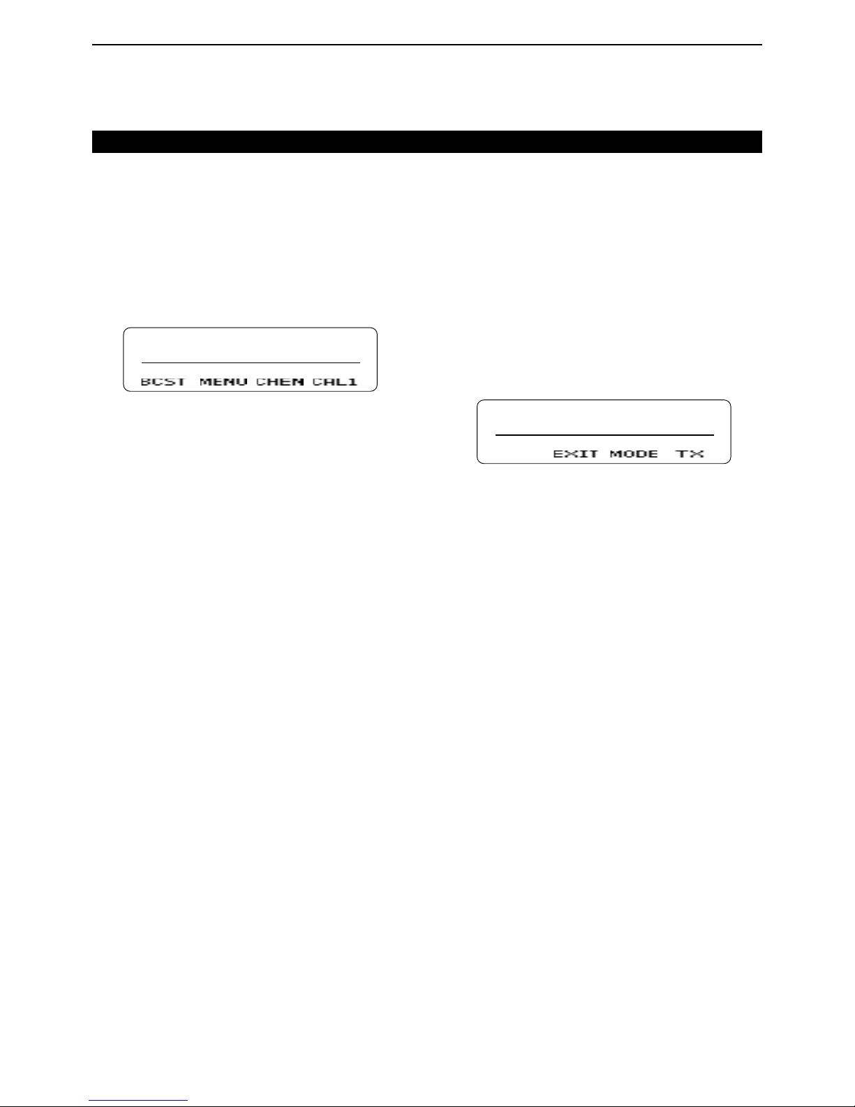
7
NXDN OPERATION <TRUNKING MODE>
7-7
Broadcast Group call D
When you use the Broadcast Group call function, you
can transmit a signal to transceivers that are set to the
same Group ID.
When you set GID to “ALL,” you can make the Broadcast Group call to all transceivers.
Select a desired GID. (p. 7-3) q
Push [Broadcast] once or twice to select “BRDCAST w
ON.”
BRDCAST ON
Push [PTT] to make a Broadcast Group call. e
Status call D
The Status call is a simple message function to transmit and receive a status message. A transceiver can
display the status message quickly. You cannot transmit
a voice signal at the same time.
Push [Status (NXDN)] to enter the Status Message q
Select mode.
• Displays “STATUS.”
Push [UP] or [DOWN] to select a desired status w
message.
• If you want to directly enter a status message, push [P2]
(MODE) to select the Status Message Entry mode.
You can enter a status message between 1 and 207.
• You can use the 10-keypad keys on the microphone.
STATUS
STATUS 001
Push [P3](TX) or [PTT] to send the selected Status e
Message.
• Displays “SEND DATA” and then “COMPLETE.”
Transmitting a call (Continued)
Page 51

7
NXDN OPERATION <TRUNKING MODE>
7-8
Short Data call D
You can send a Short Data message of up to 100 characters.
If you turn OFF the transceiver’s power, the message
is cleared.
Push [SDM (NXDN)] to enter the Short Data Mes- q
sage Entry mode.
• Displays “MESSAGE?”.
MESSAGE?
Push [UP] or [DOWN] to enter a character, and then w
push [P1](SET) to set.
• Goes to the next character entry position.
• You can use the 10-keypad keys on the microphone.
Repeat step e w until you enter a message of up to
100 characters.
• Push [P0](DEL) to delete a character.
• Push [P2](Ω) or [P3](≈) left or right to select a charac-
ter.
SHORT MESSAG
Push [PTT] to send. e
• Displays “SEND DATA” and then “COMPLETE.”
Push [P1](EXIT) to exit. r
If you exit from the Short Data Message Entry mode,
and then you want to send the message again, do the
following steps.
Push [SDM (NXDN)] to enter the Short Data Mes- q
sage Entry mode.
• Displays the entered message.
• Displays the last part of the message if the message is
over 12 characters.
HORT MESSAGE
Push [PTT] to send. w
• Displays “SEND DATA” and then “COMPLETE.”
Push [P1](EXIT) to exit. e
Transmitting a call (Continued)
Long Data call D
You can send a Long Data message of up to 4,096
characters only by using an external device, such as a
PC. You cannot send a Long Data message by pushing
[PTT].
Page 52

7
NXDN OPERATION <TRUNKING MODE>
7-9
Telephone call D
If you use the Telephone Call function, you can communicate with a telephone through the telephone lines
(PSTN, PABX, and so on).
You can call from a transceiver to a telephone, or call
from a telephone to a transceiver.
Push [Autodial]. q
• The rst entry in the Autodial list appears.
Push [UP] or [DOWN] to select your desired tele- w
phone number.
Push [P3](TX) or [PTT] to start a Telephone call e
• Displays “CALLING.”
• Displays “PHONE CALL” when the transceiver connects
to the telephone line.
Displays “INVALID” when the transceiver cannot connect
to the line.
Hold down [PTT] to talk. r
The telephone line will disconnect when you push t
[R] or microphone’s [M], or when the microphone is
on-hook (depending on the presetting).
Transmitting a call (Continued)
Page 53

7
NXDN OPERATION <TRUNKING MODE>
7-10
Receiving a call
Individual call D
When you receive an Individual call that includes your
unit ID, your transceiver informs you of the call by
sounding beeps and blinking “ ” on the function display. In addition, you can easily call back to the calling
station.
When you receive an Individual call that includes q
your unit ID:
• Beeps sound.
• Displays the caller’s unit ID.*
* Alternately displays the caller’s unit ID and “INCOMING,”
when you receive a “Message Trunked” type call, and
the Automatic Response function is OFF.
• “
” blinks for about 10 seconds.
UID 0001
To call back to the caller station, push [PTT] while w
“ ” is blinking.
Group call D
When you receive a Group call that includes a matched
GID, your transceiver informs you of the call by sounding beeps and blinking “ ” on the function display. In
addition, you can easily call back to the calling station.
When you receive a Group call that includes a q
matched GID:
• Beeps sound.
• Displays the caller’s unit ID and GID.
• “
” blinks for about 10 seconds.
UID 0001
GID 0002
To call back to the caller station, push [PTT] while w
“
” is blinking.
Page 54
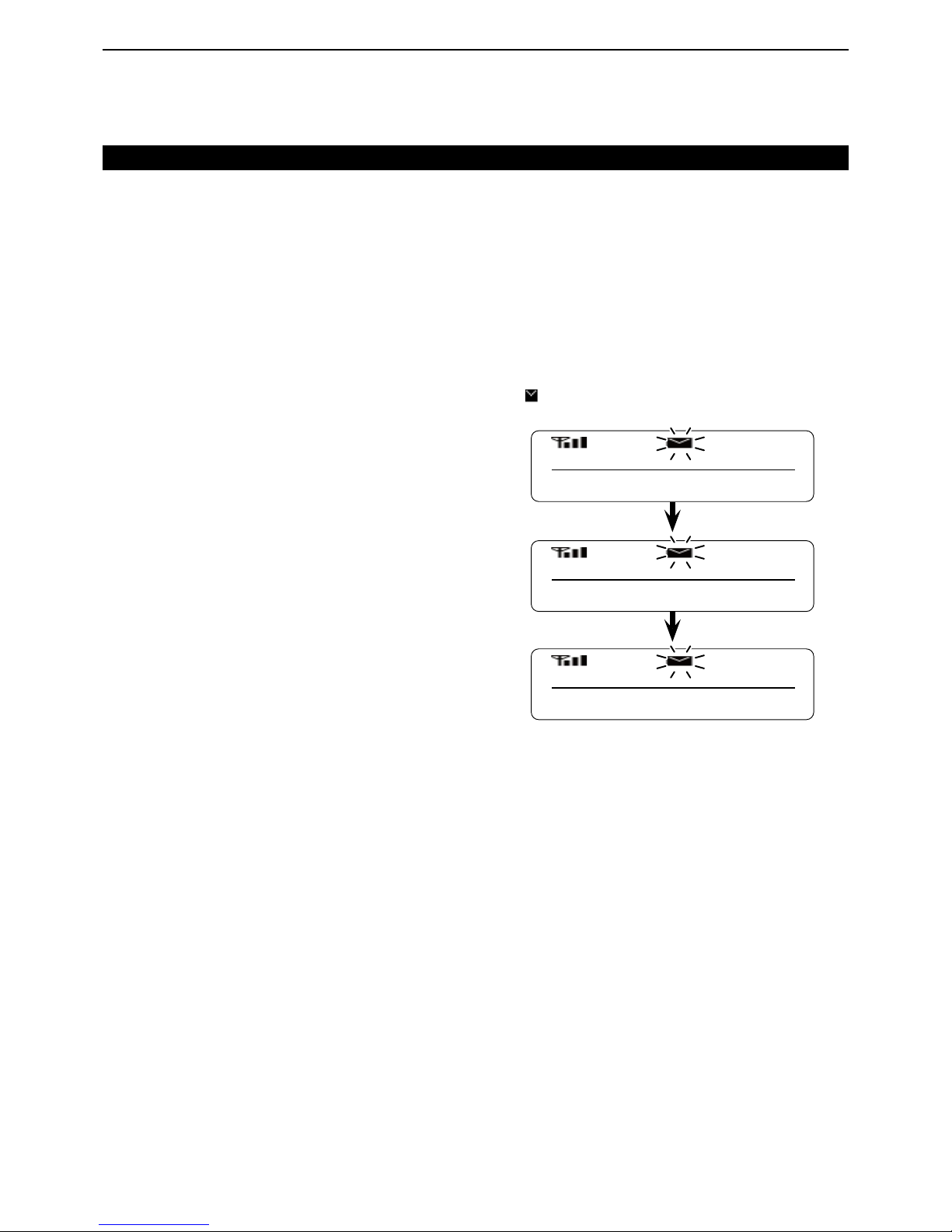
7
NXDN OPERATION <TRUNKING MODE>
7-11
Broadcast Group call D
When a Broadcast Group Call is made, the transceivers with the same selected Group ID will receive the
call.
You cannot transmit a reply to the calling transceiver.
When your transceiver receives a Broadcast Group
Call, beeps sound.
While your transceiver is receiving the call, the musical
tone icon blinks on the function display.
Receiving a call (Continued)
Status call D
When you receive a Status call, your transceiver displays a received status message on the function display.
The received message is stored in the Memory Stack,
and you can view the message contents in the memory.
(p. 6-3)
When you receive a Status call: ➥
• Beeps sound.
• Displays “DATA RCVD,” “COMPLETE,” the received mes-
sage, the caller’s unit ID and GID*.
*Displayed only when the received call is a Group call.
• “
” blinks on the function display.
The message is stored in the Memory Stack.
UID 0001
GID 0002
COMPLETE
STATUS 001
Page 55

7
NXDN OPERATION <TRUNKING MODE>
7-12
Short Data call D
When you receive a Short Data message, your transceiver displays the message on the function display.
The message is stored in the Memory Stack, and you
can view the message in the memory. (p. 6-3)
When you receive a Short Data message: ➥
• Beeps sound.
• Displays “DATA RCVD,” “COMPLETE,” the received mes-
sage, the caller’s unit ID and GID*.
*Displayed only when the received call is the Group call.
• “
” blinks on the function display.
The message is stored in the Memory Stack.
Long Data call D
You can receive a Long Data message of up to 4,096
characters. The message can be output to a PC or external device from your transceiver.
Receiving a call (Continued)
UID 0001
GID 0002
COMPLETE
SHORT MESSAG
DATA RCVD
Scrolls when the received message is
over 12 characters.
Page 56

7
NXDN OPERATION <TRUNKING MODE>
7-13
Telephone call D
When you receive a call from a telephone, you can communicate with it through the telephone lines (PSTN,
PABX, and so on).
When a telephone calls your transceiver, the transceiver sounds beeps, and then “PHONE” is displayed on
the function display.
Hold down [PTT] to talk to the telephone.
Receiving a call (Continued)
Page 57

7
NXDN OPERATION <TRUNKING MODE>
7-14
Forced Search
If you use the Forced Search function, the transceiver
searches for other Control channels using the following
hunt sequences.
Hunt sequence Explanation
Preferential Hunt Sequence
The transceiver searches for a Control channel that is set as the
Preferential Hunt Control channel.
The transceiver selects this Control channel with a high priority.
Normal Hunt Sequence
The transceiver searches for a Control channel that is set as the
Normal Hunt Control channel.
System Add Channel Sequence
The transceiver searches for up to 8 Control channels that are
added by the system.
Site Hunt Sequence
The transceiver searches for a Control channel that is set as the
Site Hunt Control channel in each site.
Comprehensive Hunt Sequence
The transceiver searches for a Control channel that is set in the
network frequency table.
Hold down [Forced Search Function] for 2 seconds q
to turn ON the Forced Search Function.
• Displays the current site number.
The transceiver starts to search for a Control chan- w
nel signal.
• Displays “SEARCHING.”
When the transceiver finds and registers to a control e
channel, the normal screen is displayed on the function display.
Page 58

8-1
Section 8
NXDN OPERATION <CONVENTIONAL MODE>
NXDN Conventional operation ...............................................8-2
Transmitting a call ...................................................................8-3
Group call D ................................................................................8-3
Individual call D ...........................................................................8-4
Individual Call Acknowledge Request call D ...............................8-4
Status call D ................................................................................8-5
Short Data call D .........................................................................8-5
Long Data call D .........................................................................8-5
Receiving a call ........................................................................8-6
Group call D ................................................................................8-6
Individual call D ...........................................................................8-6
Individual Call Acknowledge Request call D ...............................8-7
Status call D ................................................................................8-7
Short Data call D .........................................................................8-8
Long Data Call D .........................................................................8-8
Mixed Mode ..............................................................................8-9
Page 59

8
NXDN OPERATION <CONVENTIONAL MODE>
8-2
NXDN Conventional operation
When you select the NXDN Conventional system
mode, you must manually search for and select a clear
channel.
The system setup is easier than the Trunking mode.
Page 60
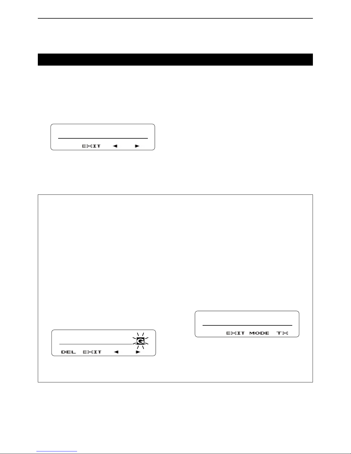
8
NXDN OPERATION <CONVENTIONAL MODE>
8-3
Transmitting a call
For your reference:
When [Group + SDM (NXDN)] or [Group + Status
(NXDN)] is assigned, you can send a message along
with a Group call.
To send a Short Data Message with a Group call.
Push [Group + SDM (NXDN)] to enter the GID Se- q
lect mode.
• Displays “SELCALL.”
Push [UP] or [DOWN] to select a desired GID. w
Push [P1](ENT). e
• Enters the Short Data Message Entry mode.
Push [UP] or [DOWN] to enter a character, and then r
push [P1](SET) to set.
• Goes to the next character entry position.
• You can use the 10-keypad keys on the microphone.
Repeat step t r until you enter a message of up to
100 characters.
• Push [P0](DEL) to delete a character.
• Push [P2](Ω) or [P3](≈) left or right to select a charac-
ter.
SHORT MESSAG
Push [PTT] to send the message to the selected y
GID.
Push [P1](EXIT) to exit. u
To send a Status Message with a Group call.
Push [Group + Status (NXDN)] to enter the GID Se- q
lect mode.
• Displays “SELCALL.”
Push [UP] or [DOWN] to select a desired GID. w
Push [P1](ENT). e
• Enters the Status Message Entry mode.
Push [UP] or [DOWN] to select a desired status r
message.
• If you want to directly enter a status message, push [P2]
(MODE) to select the Status Message Entry mode.
You can enter a status message between 1 and 207.
• You can use the 10-keypad keys on the microphone.
STATUS
STATUS 001
Push [P3](TX) or [PTT] to send the message to the t
selected GID.
Push [P1](EXIT) to exit. y
Group call D
When you select the NXDN Conventional System zone,
you can make a Group call by using the Group Call
function.
Set GID to “ALL,” to call all transceivers.
Push [Group (NXDN)] to enter the GID Select mode. q
• Displays “SELCALL.”
SELCALL
GID 0001
Push [P2]( w Ω) or [P3](≈) to select the desired GID.
Push [PTT] to make a Group call. e
Push [P1](EXIT). r
Page 61

8
NXDN OPERATION <CONVENTIONAL MODE>
8-4
Transmitting a call (Continued)
Individual call D
You can call a specified station that is set to the same
unit ID by using the Individual call function.
Push [Individual (NXDN)] to enter the Unit ID Select q
mode.
• Displays “SELCALL.”
SELCALL
UID 0001
Push [UP] or [DOWN] to select a desired unit ID. w
• If you want to directly enter an unit ID, push [P2](MODE)
to select the Unit ID Entry mode.
You can enter an unit ID between 1 and 65519.
Push [P3](TX) or [PTT] to make the Individual call. e
Push [P1](EXIT). r
For your reference:
When [Individual + SDM (NXDN)] or [Individual + Status (NXDN)] is assigned, you can send a message
along with an Individual call.
To send a Short Data Message with an Individual call.
Push [Individual + SDM (NXDN)] to enter the unit ID q
Select mode.
• Displays “SELCALL.”
Push [UP] or [DOWN] to select a desired unit ID. w
Push [P1](ENT). e
• Enters the Short Data Message Entry mode.
Push [UP] or [DOWN] to enter a character, and then r
push [P1](SET) to set.
• Goes to the next character entry position.
• You can use the 10-keypad keys on the microphone.
Repeat step t r until you enter a message of up to
100 characters.
• Push [P0](DEL) to delete a character.
• Push [P2](Ω) or [P3](≈) left or right to select a charac-
ter.
SHORT MESSAG
Push [PTT] to send the message to the selected y
unit ID.
Push [P1](EXIT) to exit. u
To send a Status Message with an Individual call.
Push [Individual + Status (NXDN)] to enter the unit q
ID Select mode.
• Displays “SELCALL.”
Push [UP] or [DOWN] to select a desired unit ID. w
Push [P1](ENT). e
• Enters the Status Message Entry mode.
Push [UP] or [DOWN] to select a desired status r
message.
• If you want to directly enter a status message, push [P2]
(MODE) to select the Status Message Entry mode.
You can enter a status message between 1 and 207.
• You can use the 10-keypad keys on the microphone.
STATUS
STATUS 001
Push [P3](TX) or [PTT] to send the message to the t
selected unit ID.
Push [P1](EXIT) to exit. y
Individual Call Acknowledge Request call D
When the Individual Call Acknowledge Request function is set, you can transmit an acknowledgement request signal with the Individual call.
Therefore, you can confirm whether the transceiver is
located in the communication range or not.
Push [Individual (NXDN)] to enter the Unit ID Select q
mode.
• Displays “SELCALL.”
Push [UP] or [DOWN] to select a desired unit ID. w
• If you want to directly enter an unit ID, push [P2](MODE)
to select the Unit ID Entry mode.
You can enter an unit ID between 1 and 65519.
Push [P3](TX) or [PTT] to make the Individual call e
with an acknowledgement request signal.
• Displays “CALLING,” and then after receiving an acknowledgement, displays “HOLDING.”
When the called station calls back, the transceiver r
displays the called station’s unit ID.
• Displays “NO REPLY” and sounds error beeps when your
transceiver does not receive an acknowledgement within
the preset time period.
Page 62

8
NXDN OPERATION <CONVENTIONAL MODE>
8-5
Transmitting a call (Continued)
Status call D
The status call is a simple message function to transmit
and receive a status message. A transceiver can display the status message quickly. You cannot transmit a
voice signal at the same time.
Push [Status (NXDN)] to enter the Status Message q
Select mode.
• Displays “STATUS.”
Push [UP] or [DOWN] to select a desired status w
message.
• If you want to directly enter a status message, push [P2]
(MODE) to select the Status Message Entry mode.
You can enter a status message between 1 and 207.
• You can use the 10-keypad keys on the microphone.
STATUS
STATUS 001
Push [P3](TX) or [PTT] to send the selected Status e
Message.
• Displays “SEND DATA” and then “COMPLETE.”
Short Data call D
You can send a Short Data message of up to 100 characters.
If you turn OFF the transceiver’s power, the message
is cleared.
Push [SDM (NXDN)] to enter the Short Data Mes- q
sage Entry mode.
• Displays “MESSAGE?”.
MESSAGE?
Push [UP] or [DOWN] to enter a character, and then w
push [P1](SET) to set.
• Goes to the next character entry position.
• You can use the 10-keypad keys on the microphone.
Repeat step e w until you enter a message of up to
100 characters.
• Push [P0](DEL) to delete a character.
• Push [P2](Ω) or [P3](≈) left or right to select a charac-
ter.
SHORT MESSAG
Push [PTT] to send. r
• Displays “SEND DATA” and then “COMPLETE.”
Push [P1](EXIT) to exit. t
If you exit from the Short Data Message Entry mode,
and then you want to transmit the message again, do
the following steps.
Push [SDM (NXDN)] to enter the Short Data Mes- q
sage Entry mode.
• Displays the entered message.
• Displays the last part of the message if the message is
over 12 characters.
HORT MESSAGE
Push [PTT] to send. w
• Displays “SEND DATA” and then “COMPLETE.”
Push [P1](EXIT) to exit. e
Long Data call D
You can send a Long Data message of up to 4,096
characters only by using an external device, such as a
PC. You cannot send a message by pushing [PTT].
Page 63
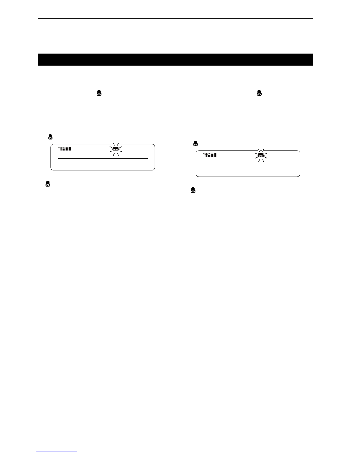
8
NXDN OPERATION <CONVENTIONAL MODE>
8-6
Receiving a call
Individual call D
When you receive an Individual call that includes your
unit ID, your transceiver informs you the calling by
sounding beeps and blinking “ ” on the function display. In addition, you can easily call back to the calling
station.
When you receive an Individual call that includes q
your unit ID:
• Beeps sound.
• Displays the caller’s unit ID.
• “
” blinks for about 10 seconds.
UID 0001
To call back to the caller station, push [PTT] while w
“
” is blinking.
Group call D
When you receive a Group call that includes a matched
GID, your transceiver informs you the calling by sounding beeps and blinking “ ” on the function display. In
addition, you can easily call back to the calling station.
When you receive a Group call that includes a q
matched GID:
• Beeps sound.
• Displays the caller’s unit ID and GID.
• “
” blinks for about 10 seconds.
UID 0001
GID 0002
To call back to the caller station, push [PTT] while w
“
” is blinking.
Page 64
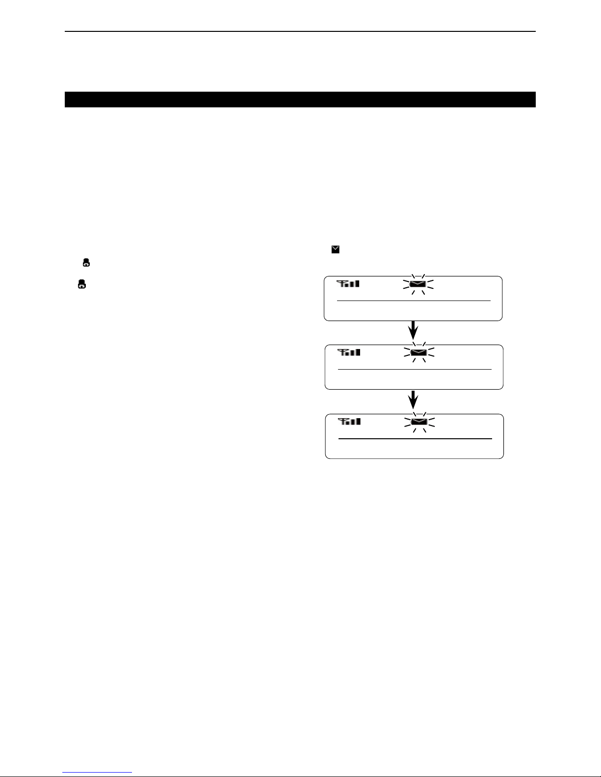
8
NXDN OPERATION <CONVENTIONAL MODE>
8-7
Receiving a call (Continued)
Individual Call Acknowledge Request call D
When you receive an Individual Call with an acknowledgement request which includes your own Individual
ID, your transceiver automatically transmits a acknowledgement signal, and informs you the calling by beep
sounds and bell mark blinks on the function display. In
addition, you can easily call back to the calling transceiver.
When you receive an Individual call with an acknowl- q
edgement request signal that includes your unit ID:
• Beeps sound.
• Alternately displays the caller’s unit ID and “INCOMING.”
• “
” blinks for about 30 seconds.
To call back to the caller station, push [PTT] while w
“ ” is blinking.
Status call D
When you receive a Status call, your transceiver displays a received status message on the function display.
The received message is stored in the Memory Stack,
and you can view the message contents in the memory.
(p. 6-3)
When you receive a Status call: ➥
• Beeps sound.
• Displays “DATA RCVD,” “COMPLETE,” the received mes-
sage, the caller’s unit ID and GID*.
*Displayed only when the received call is the Group call.
• “
” blinks on the function display.
The message is stored in the Memory Stack.
UID 0001
GID 0002
COMPLETE
STATUS 001
Page 65
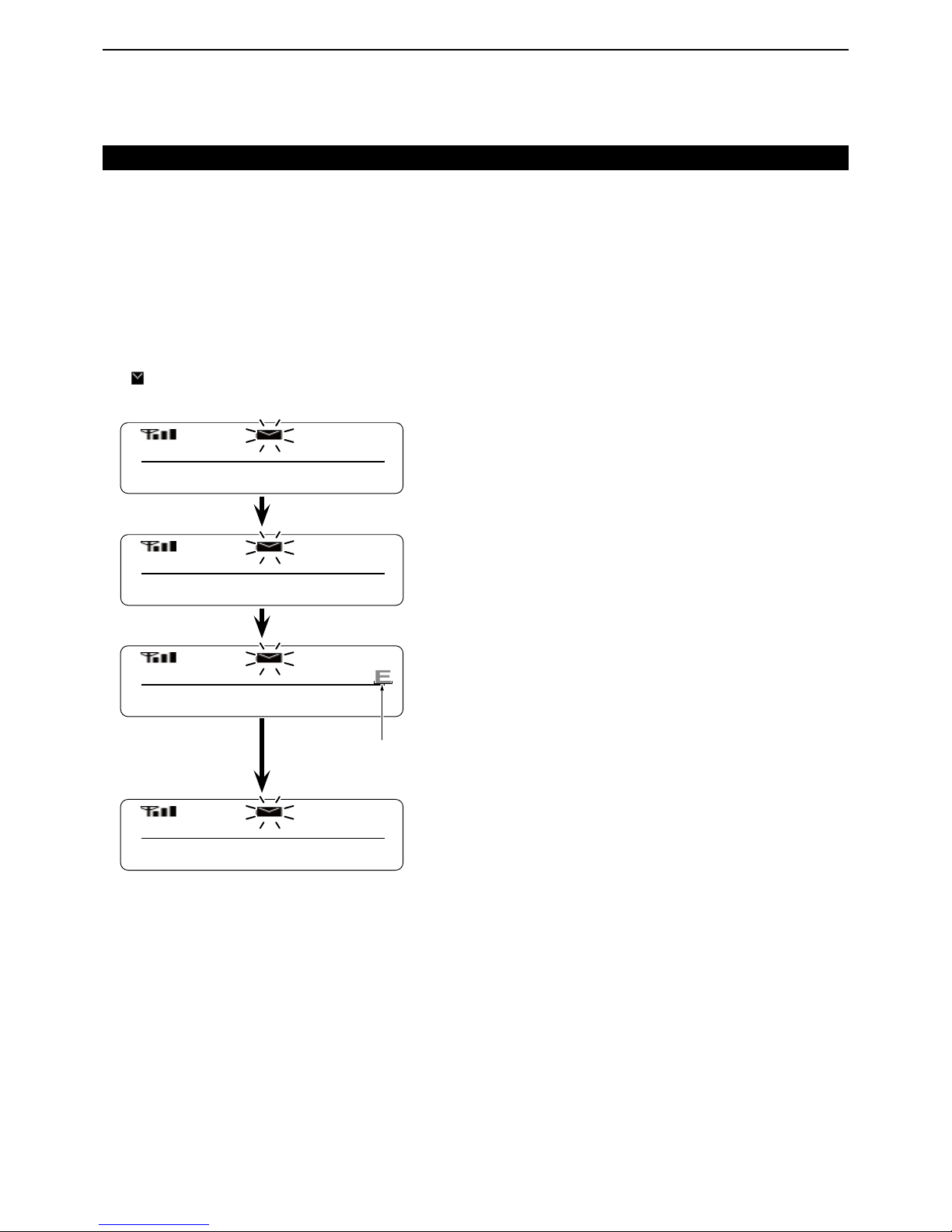
8
NXDN OPERATION <CONVENTIONAL MODE>
8-8
Long Data Call D
You can receive a Long Data message of up to 4,096
characters. The message can be output to a PC or external device from your transceiver.
Receiving a call (Continued)
Short Data call D
When you receive a Short Data message, your transceiver displays the message on the function display.
The message is also stored in the Memory Stack, and
you can view the message in the memory. (p. 6-3)
When you receive a Short Data message: ➥
• Beeps sound.
• Displays “DATA RCVD,” “COMPLETE,” the received mes-
sage, the caller’s unit ID and GID*.
*Displayed only when the received call is the Group call.
• “
” blinks on the function display.
The message is stored in the Memory Stack.
UID 0001
GID 0002
COMPLETE
SHORT MESSAG
DATA RCVD
Scrolls when the received message is
over 12 characters.
Page 66

8
NXDN OPERATION <CONVENTIONAL MODE>
8-9
Mixed Mode
If you set your transceiver to the Mixed mode, you can
receive both digital and analog signals. You can use a
digital transceiver on analog channels, therefore you
can easy switch from an analog system to a digital system.
Page 67
1-1-32 Kamiminami, Hirano-ku, Osaka 547-0003, Japan
A-7148-3EX-q
© 2014 Icom Inc.
 Loading...