

Page 1

INSTRUCTION MANUAL
VHF TRANSCEIVER
iF3/S
UHF TRANSCEIVER
iF4/S
This device complies with Part 15 of
the FCC Rules. Operation is subject to
the condition that this device does not
cause harmful interference.
Page 2

IMPORTANT
TABLE OF CONTENTS
READ ALL INSTRUCTIONS carefully and completely before
using the transceiver.
SAVE THIS INSTRUCTION MANUAL. This manual contains
important safety and operating instructions for the IC-F3,
IC-F3S,
IC-F4 and IC-F4S.
CAUTIONS
NEVER allow the antenna to come close to, or touch, ex-
posed body parts, especially the face or eyes while transmitting.
NEVER disassemble the transceiver. Incorrect reassembly
may result in a fire hazard or electric shock.
NEVER operate the transceiver near unshielded electrical
blasting caps or in an explosive area.
AVOID the use of chemical agents such as benzene or al-
cohol when cleaning—use a water-dampened cloth only.
For U.S.A. only
Caution: Changes or modifications to this transceiver, not expressly approved by Icom Inc., could void your authority to
operate this transceiver under FCC regulations.
Versions of the IC-F3/IC-F4 which display “CE” on the serial number seal, comply with the essential requirements of the 89/336/EEC
directive for Electromagnetic Compatibility.
i
IMPORTANT ..........................................................................i
CAUTIONS ............................................................................i
TABLE OF CONTENTS.........................................................i
1 GETTING STARTED.........................................................1
2 PANEL DESCRIPTION .....................................................2
3 DEALER-PROGRAMMABLE FUNCTIONS .................3–6
‘ General........................................................................3
‘ Functions.....................................................................4
4 CONVENTIONAL OPERATION....................................7–8
TM
5 SmarTrunk II
6 OPTIONAL INSTALLATION............................................11
7 BATTERY PACKS.....................................................12–16
‘ Battery pack replacement..........................................12
‘ Cautions ....................................................................12
‘ Charging....................................................................14
8 SPECIFICATIONS AND OPTIONS.................................17
‘ Specifications ............................................................17
‘ Options ......................................................................17
SmarTrunk IITMis a trademark of SmarTrunk Systems,Inc.
OPERATION .....................................9–10
Page 3
Attach the belt-clip
Release the belt-clip
q
w
e
GETTING STARTED
MR
1
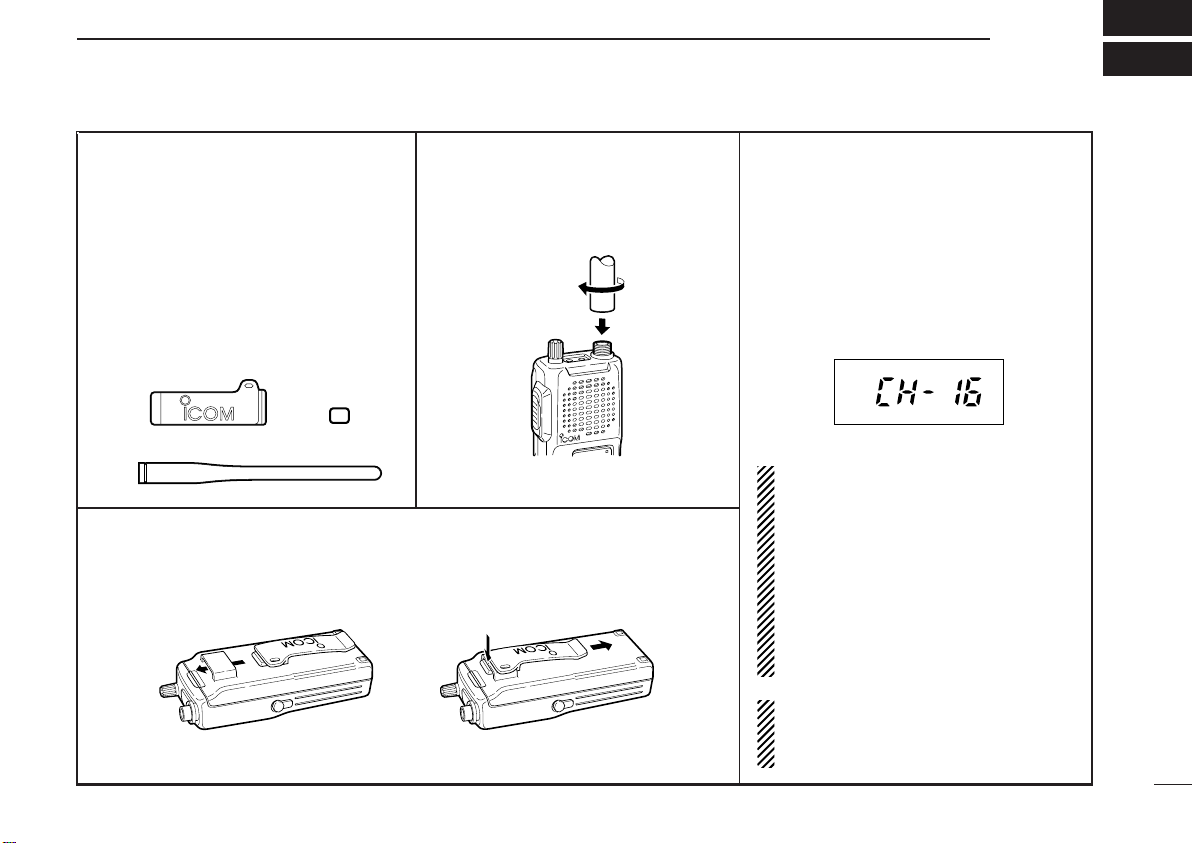
D UNPACKING
The transceiver comes supplied with
the following accessories*.
q Flexible antenna
w Belt clip
e 1922A REAR-SHEET
*The BP-196 BATTERY PACK comes at-
tached to the transceiver.
D BELT CLIP
Attach the belt clip to the transceiver as illustrated below.
D ANTENNA
The antenna screws onto the transceiver as illustrated below.
D TURNING POWER ON
Rotate the volume control to the 12 o’clock
position.
•A power-up alert tone sounds for about
2 sec. and an opening message may
appear.
(Above functions depend on pre-setting.)
Then a channel number appears on the
display.
Channel number may differ from this.
NOTE: If the power-up alert tone does
not sound or a channel number does
not appear on the display, turn the
transceiver OFF, check the battery,
then turn the transceiver back ON.
If the power-up tone still does not
sound or a channel number does not
appear, charge the battery or replace
it.
NOTE: To increment or decrement the
displayed channel, push [Y] or [Z]
keys.
1
Page 4
2
y
u
q
w
e
r
i
o
t
y
u
q
w
e
r
i
o
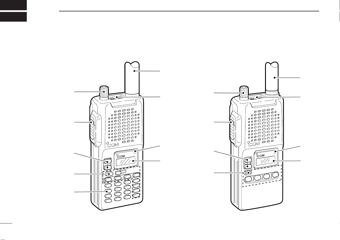
PANEL DESCRIPTION
IC-F3,IC-F4 IC-F3S,IC-F4S
2
Page 5

DEALER-PROGRAMMABLE FUNCTIONS
3
q VOLUME CONTROL [OFF/VOL]
Turns power ON and adjusts the audio level.
w PTT SWITCH [PTT]
Push and hold to transmit; release to receive.
e UP/DOWN KEYS [Y]/[Z]
• Push to select the operating channel.
• Can be programmed as [
r DEALER-PROGRAMABLE KEYS
[P0]/[P1]/[P2]/[P3]/[A]/[B]/[C]/[D]/ [Ω]/[ ]/[––]
Can each be programmed for one of
several functions by your Icom Dealer (see right).
t KEYPAD
Used to enter DTMF codes, the operating channel, etc.
y ANTENNA CONNECTOR
Connects the supplied antenna.
u [SP]/[MIC] JACK
Connect optional speaker-microphone.
i ACTIVITY LED
Lights red while transmiting.
o FUNCTION DISPLAY
Displays the following the information:
• CH number.
• 5-tone indication.
• Low-battery indication.
• DTMF numbers.
• Low-power indication.
• Skip-ch indication.
• Audible indication.
NOTE: Above functions depend on presetting.
MM
]/[ # ]. (SmarTrunk mode only)
■ General
Consult your Icom Dealer or System operator for details concerning your transceiver’s programming. When available, programmed functions are assigned to [P0], [P1], [P2], [P3],
1,
[A]*
[B]*1, [C]*1, [D]*1, [ΩΩ]*1, [ ]*1, [ – ]*2and [YY]/[ZZ]*3.
*1: IC-F3/IC-F4 only.
*2: IC-F3S/IC-F4S only.
*3: SmarTrunk II mode when assigned [MM]/[ # ] functions only.
DD
Programmable key reference.
IC-F3/IC-F4
[ Y ]
[ Z ]
[ P0 ] [ A ]
[ P1 ] [ B ]
[ P2 ]
[ P3 ] [ D ]
IC-F3S/IC-F4S
[ Y ]
[ Z ]
[ – ] [ P2 ]
[]
[ Ω ]
[ C ]
[ P0 ]
[ P1 ]
[ P3 ]
3
Page 6

3
DEALER-PROGRAMMABLE FUNCTIONS
■ Functions
In the following explanations, programmable function names
are bracketed, the specific switch used to activate the function depends on programming.
DD
KEYPAD LOCK FUNCTION
This function locks access to all programmable switches (except the switch assigned the lock function).
To toggle the lock function ON and OFF:
Push and hold the [LOCK] switch for 1 sec.
•
“”appears while the lock function is ON.
• This function may be inhibited on some channels.
DD
PRIORITY CHANNEL
This function is used to select a pre-programmed channel at
the push of a switch.
To select the priority channel:
Push the [PRIORITY] switch.
•“PRIO” appears briefly, then the priority channel is automatically se-
lected.
DD
SCAN FUNCTION
The scan function allows you to search a pre-programmed
group of channels for signals.
To start/stop scan:
Push the [SCAN] switch.
• Scan pauses on a channel when receiving a signal.
•Depending on programming, a message may appear while scan-
ning.
•“Lockout SCAN" (pre-programmed list SCAN) or “Priority SCAN”
can be pre-programmed.
•When the “Power-save function” is activated, the transceiver checks
all pre-programmed channels then returns to the “Power-save func-
tion” again.
DD
BEEP FUNCTION
This function provides confirmation beep tones when pushing switches.
To toggle the function ON and OFF:
Push the [BEEP] switch.
4
Page 7

DD
P0 P1 P2 P3
12
5
8
0
4
79
6
3
A
B
C
D
All signals are
received
P0 P1 P2 P3
12
5
8
0
4
79
6
3
A
B
C
D
Only signals
containing
the proper
tone are
received
MONITOR AUDIBLE FUNCTION
The monitor function allows you to open the transceiver’s
squelch manually to check whether a channel is busy or not.
The transceiver has 2 conditions for receive standby:
Audible condition:
This condition mutes audio ONLY
when no carrier is present. You can receive (or monitor) any signals on a
channel.
•
Push and hold the [MONI/AUDI], switch to
select the audible condition.
Any audio mute functions are cancelled
while pushing the [MONI/AUDI] switch.
Inaudible condition:
This condition mutes ALL signals except those directed to you. Therefore
you should check a channel’s condition
(busy or not) with the monitor function
before transmitting.
•
Push the [MONI/AUDI] switch momentar-
ily to select the inaudible condition.
DEALER-PROGRAMMABLE FUNCTIONS
DD
TALK AROUND
3
The talk around function changes duplex channels to simplex
channels.
•Duplex allows you to contact your base station, repeaters,
etc.
•Simplex allows you to contact other portable transceivers
directly (portable-to-portable contact).
To toggle the talk around function ON and OFF:
Push the [TALK AROUND] switch one or more times.
DD
DTMF TRANSMISSION
This function allows you to send a pre-programmed DTMF
code to control a repeater, open another transceiver’s
squelch, etc.
Manual transmission:
Push desired digit keys in sequence while pushing [PTT].
• Pushing [PTT] may not be necessary depending on programming.
Automatic pre-programmed transmission:
q Push the [DTMF] switch to select DTMF autodial mode
then push [Y] or [Z] to select the desired channel.
w Push the [DTMF] switch once more to send a DTMF code.
5
Page 8

3
DEALER-PROGRAMMABLE FUNCTIONS
DD
DTMF RE-DIAL FUNCTION
This function allows you to transmit the last-used DTMF code
•The emergency call is repeatedly transmitted at pre-programmed in-
tervals.
at the push of a key.
DD
To activate the function:
Push the [DTMF RE-DIAL] switch momentarily.
•The previously transmitted DTMF code is automatically transmitted.
•If no code has been transmitted since turning the power ON, this
function does not activate.
DISPLAY LIGHTING
The function display has 3 backlight conditions.
OFF: No backlight is available.
AUTO:When any key is pushed, the backlight turns ON for 5
sec. automatically.
CONTINUOUS: Backlight turns ON continuously after power
ON.
DD
HIGH/LOW POWER OUTPUT
This function selects high or low power for a channel.
To toggle between high and low power:
Push the [HIGH/LOW] switch.
•“LOW” appears when low output power is selected.
DD
SmarTrunk II
This transceiver provides SmarTrunk II™ functions.
(Optional UT-105
TM
functions
SmarTrunk IITMLogic Board is required.)
The optional UT-105 allows communication over conventional
channels or SmarTrunk II™ channels. Select a channel bank
DD
EMERGENCY FUNCTION
for SmarTrunk II™ before trunking operation.
The emergency function allows you to send your ID quickly
and easily to your Base Station, etc. in case of emergency.
To toggle SmarTrunk IITMchannels and conventional channels.
To activate the emergency function:
Push and hold the [EMERGENCY] switch for 1 sec.
•The transceiver selects a pre-programmed channel, then sends an
emergency signal to your Base Station.
•The pre-programmed channel remains selected until a control signal
is received from the Base Station or power is turned OFF.
Push the [Bank Up] switch one or more times.
•Scanning starts when a channel bank for SmarTrunk II™ is selected.
•Contact your dealer for channel bank details.
(See p.9 for more detailed operation.)
6
Page 9

CONVENTIONAL OPERATION
P0 P1 P2 P3
12
5
8
0
4
79
6
3
A
B
C
D
P0 P1 P2 P3
12
5
8
0
4
79
6
3
A
B
C
D
P0 P1 P2 P3
12
5
8
0
4
79
6
3
A
B
C
D
P0 P1 P2 P3
12
5
8
0
4
79
6
3
A
B
C
D
P0 P1 P2 P3
12
5
8
0
4
79
6
3
A
B
C
D
P0 P1 P2 P3
12
5
8
0
4
79
6
3
A
B
C
D
P0 P1 P2 P3
12
5
8
0
4
79
6
3
A
B
C
D
P0 P1 P2 P3
12
5
8
0
4
79
6
3
A
B
C
D
Non-selective calling
Selective calling
4
■ Receiving and transmitting
NOTE: Transmitting without an antenna may damage the
transceiver. See p.1 for antenna attachment.
Turn power ON as described on p.1.
Receiving:
q Push [Y]/[Z] to select a channel.
w Listen for a transmission and adjust [VOL] to a comfortable
listening level.
•
When no transmission is heard, push and hold monitor while adjusting [VOL] (your transceiver may not be programmed with the
monitor function).
The transceiver is now set to receive desired calls on the selected channel.
Transmitting:
Wait for the channel to become clear to avoid interference.
e While pushing and holding [PTT], speak into the micro-
phone at a normal voice level.
•
When a tone signalling system is used, the call procedure described at right may be necessary.
r Release [PTT] to return to receive.
IMPORTANT: To maximize the readability of your transmitted signal, pause a few secs. after pushing [PTT], hold
the microphone 10 to 15 cm from your mouth and speak
at a normal voice level.
■ Call procedure
When your system employs tone signalling (excluding
CTCSS and DTCS), the call procedure may be necessary
prior to voice transmission. The tone signalling employed may
be a selective calling system which allows you to call specific
station(s) only and prevent unwanted stations from contacting you.
q Select the desired Tx code channel or 5-tone code ac-
cording to your System Operator’s instructions.
• This may not be necessary depending on programming.
• Refer to the next page for selection.
w Push the call switch (assigned to one of the dealer pro-
grammable switches: [P0], [P1], [P2], [P3], [A], [B], [C], [D],
[Ω], [ ] and [––]).
e After transmitting a 5-TONE code, the remainder of your
communication can be carried out in the normal fashion.
7
Page 10

4
Holding PTT
Transmitting
Specified TOT period
CONVENTIONAL OPERATION
■ Tx code channel selection
Your radio may be programmed for Tx code channel selection. In this case, you can choose a Tx code channel to be
transmitted when using the call function (p.7).
Push the Tx code channel switch (assigned to one of the
dealer-programmable switches) to activate the function, then
enter digits via the keypad to select the desired Tx code
channel.
•
The selected code channel (containing a pre-programmed 5-tone
code) is transmitted when using the call function.
■ Manual 5-tone codes
Depending on programming, you may be able to send 5-tone
codes manually.
Push the Tx code switch to activate the function, then enter
the desired transmit code (up to 7 digits) using the keypad.
• Activate the call function to transmit the 5-tone code.
• Blinking indicates keypad entry is acceptable.
■ Transmitting notes
DD
LOW BATTERY INDICATION
- When appears, battery capacity is becoming low and
transmitting is impossible.
- When flashes, battery capacity is nearly exhausted.
DD
TIME-OUT TIMER
After continuous transmission for a pre-programmed period,
the time-out timer is activated, causing the transceiver to stop
transmitting and automatically select receive.
DD
PENALTY TIMER
Once the time-out timer is activated, transmission is further
inhibited for a period determined by the penalty timer.
8
Page 11

SmarTrunk II
TM
OPERATION
5
■ Basic operation
These features are enabled by your Dealer or System
Operator and may not be available in your system. Contact
your Dealer for details.
Push the [Bank Up] switch one or more times to select a
channel bank for conventional channels or SmarTrunk II™
channels.
• Scanning starts when a channel bank for SmarTrunk II™ is
selected.
DD
PTT dispatch operation *
q Push [PTT] once (without dialing) to initiate a dispatch call.
w Begin talking after you hear three beeps (one short, high-
pitched, two very-short, low-pitched).
e Receiving a dispatch call is indicated by the same three-
beep sequence.
• It is not necessary to push [
DD
System busy indication
If all channels are busy, three low beeps sound after you initiate a call. Try the call again later.
1
M] to answer a dispatch call.
DD
Receiving a subscriber-to-subscriber call
When you hear ringing, push [M] to answer.
• For a group call, you hear a short ring followed by two short
beeps. You do not have to answer a group call to hear it over
the air.
DD
Receiving a landline-to-subscriber call *
When you hear ringing, push [M] to answer.
• For a group call, you hear a short ring followed by two short
beeps. You do not have to answer a group call to hear it over
the air.
DD
Terminating a call *
After completing a call, push [#] to disconnect (hang up).
IMPORTANT: If one person in the conversation terminates a
call, all participants will be cut off.
DD
Last number redial *
Push [M], [M] to automatically redial the last number called.
• A high-pitched beep indicates that the number is accepted.
*1: This function is available to for the IC-F3S/IC-F4S when the
[YY]/[ZZ] keys are assigned the [ M ]/[ # ] key functions.
1
1
1
*
1
9
Page 12

SmarTrunk IITMOPERATION
5
DD
Clear channel alerting *
1
If all channels are busy, the transceiver automatically begins
searching for an open channel and beeps every ten seconds.
When two short beeps (low-pitched, then high-pitched) are
heard, a channel is available. Push [
M], [M] immediately to
redial the last number.
D Turbo SpeeDial
To automatically dial a commonly used number with one
push:
• Push one of the turbo SpeeDials :
IC-F3/IC-F4: [A], [B], [C] or [D]
IC-F3S/IC-F4S: [P0],[P1], [P2], [P3], or [–]
DD
Programming memory speed dial
q Push and hold [
M] until you hear a high-pitched beep.
w Enter the memory location (0–9, A, B, C, D), the telephone
or subscriber number, then [1], [
M] (or [3], [M] if for an-
other system subscriber).
• A high-pitched beep indicates successful programming.
• Memories [A]–[D] are used for the Turbo SpeeDial.
NOTE: This function is available for the IC-F3/IC-F4 only.
DD
Emergency call *
2
Push [0], [M] to initiate an emergency call.
• Contact your Dealer for details.
DD
Memory speed-dialing *
2
To automatically dial a commonly used number from memory:
• Push [
M] followed by the memory location (0–9).
DD
Placing a telephone call *
2
Enter the phone number followed by [1], [M].
• A high-pitched beep indicates that the number is accepted.
• When the called party answers, push the [PTT] switch to
talk, and release it to listen.
DD
Calling another local system subscriber *
2
Enter the subscriber number followed by [3], [M].
• A high-pitched beep indicates that the number is accepted.
• You hear ringing, then two short beeps when the subscriber
answers.
• If the other subscriber is on another call or out of range, you
hear a fast busy signal and the call terminates automatically.
*1: This function is available for the IC-F3S/IC-F4S when the
[YY]/[ZZ] keys are assigned the [ M ]/[ # ] key functions.
*2: This function is available for the IC-F3/IC-F4 only.
Use the Turbo SpeeDial function instead.
For additional operating instructions, contact your Dealer
or System Operator.
10
Page 13

OPTIONAL INSTALLATION
■ UT-80 2-TONE UNIT, UT-96 5-TONE
UNIT or UT-105 SmarTrunk II
Logic Board
Only one of the above optional units can be installed in the
IC-F3/IC-F4.
q Remove the battery pack from the transceiver as shown in
Fig. 1.
w Remove the service cover. (Fig. 2)
e Take out the protective sponge. (Fig. 2)
• This sponge is not used when options are installed.
r Connect the optional unit as shown in Fig. 2.
t Replace the service cover.
TM
6
q
(Fig. 1)
w
e
r
(Fig. 2)
11
Page 14

7
RBRC
BRC
Ni-
Cd
BATTERY PACKS
■ Battery pack replacement
Before replacing the battery pack, the volume control MUST
be rotated fully counterclockwise, until a click is heard, to turn
the power OFF.
•TO REMOVE the battery pack from the transceiver:
Push and hold the battery release downwards, then pull the
battery pack upwards with the transceiver facing you.
•TO ATTACH the battery pack to the transceiver:
Mate the notched ends of the battery pack and the transceiver, and push the battery pack until it clicks into place.
■ Battery cautions
NEVER incinerate used battery packs. Internal battery gas
may cause an explosion.
NEVER immerse the battery pack in water. If the battery pack
becomes wet, be sure to wipe it dry BEFORE attaching it to
the transceiver.
NEVER short terminals of the battery pack. Also, current may
flow into nearby metal objects so be careful when placing battery packs in handbags, etc.
If your battery pack seems to have no capacity even after
being charged, completely discharge it by leaving the power
ON overnight. Then, fully charge the battery pack again. If the
battery pack still does not retain a charge (or very little), a
new battery pack must be purchased.
D Recycling information (U.S.A. only)
The product that you have purchased contains a
rechargeable battery. The battery is recyclable. At
the end of its life, under various state and local
laws, it may be illegal to dispose of this battery
into the municipal waste stream. Call 1-800-8-BATTERY for
battery recycling options in your area or contact your dealer.
12
Page 15

BATTERY PACKS
7
■ Battery case
When using a BP-194 OPTIONAL BATTERY CASE
the transceiver, install 8 AA (R6) size alkaline or Ni-Cd batteries as illustrated below.
attached to
D Battery case cautions
When installing Ni-Cd batteries:
• Make sure all Ni-Cd cells are the same brand, type and ca-
pacity.
• Never mix old and new batteries.
Either of the above may cause a fire hazard or damage the
transceiver.
When installing dry cell or alkaline batteries:
• Never connect DC power to the transceiver. Such a con-
nection always charges the installed batteries and will damage the transceiver.
For both Ni-Cd and dry cell batteries:
• Never incinerate used battery cells since internal battery gas
may cause them to rupture.
• Never expose a detached battery case to water.
If the battery case gets wet, be sure to wipe it dry before
using.
13
Page 16

7
Turn power
OFF.
BC-119+
AD-81
BC-119+
AD-81
Check orientation
for correct charging. (Packed
together as the
AD-81.)
Check orientation
for correct charging. (Packed
together as the
AD-81.)
BATTERY PACKS
■ Battery charging
Prior to using the transceiver for the first time, the battery
pack must be fully charged for optimum life and operation.
CAUTION: To avoid damage to the transceiver, turn it
OFF while charging.
• Recommended temperature range for charging:
+10°C to +40°C (50°F to 140°F).
• Use the supplied charger or optional charger (BC-119/BC121 for rapid charging) only. NEVER use other manufacturers’ chargers.
• An optional cable OPC-254L (for 13.8 V power source) or
CP-12L (for 12 V cigarette lighter socket) can be used instead of the AC adapters supplied with the above chargers.
When using the BC-119: If the charge indicator flashes
orange, the vehicle battery voltage is low and charging
may not be performed. Check the vehicle battery voltage
in this case. If the charge indicator flashes red, there may
be a problem with the battery pack (or charger). Re-insert
the battery pack or contact your dealer.
DD
Rapid charging with the BC-119
The optional BC-119 provides rapid charging of optional NiCd battery packs.
The following are additionally required:
• One AD-81.
• An AC adapter (may be supplied with the BC-119 depending
on version).
14
Page 17

BATTERY PACKS
AC adapter
(not supplied with some versions)
M
U
L
T
I-C
H
A
R
G
E
R
Charge indicator
(each indicator functions
independently)
[CHARGE]
To
BC-110A/D/V
7
D Multiple charging with the BC-121
The optional BC-121 allows up to 6 Ni-Cd batteries to be
charged simultaneously. The following are additionally required.
• Six AD-81s.
• An AC adapter (may be supplied with the BC-121 depending
on version).
D Charging with the BC-110A/D/V
CAUTION: Only Ni-Cd batteries can be charged. NEVER
connect a wall charger when dry cell or alkaline batteries
are installed in the BP-194
transceiver and/or battery case may be damaged.
Connect the optional BC-110A/D/V to the [CHARGE] jack on
the transceiver.
• Approx. charging period: 15 hr.
• DO NOT turn power ON while connecting the BC-110A/D/V.
Current capacity is insufficient.
OPTIONAL BATTERY CASE—the
15
Page 18

7
CP-12L
(optional)
OPC-254L
(optional)
To a 12 to 16 V DC
power source
To
[CHARGE]
white
black
BATTERY PACKS
16
D Charging with an optional cables
The optional CP-12L CIGARETTE LIGHTER CABLE with noise
filter or OPC-254L
power source can also be used to charge the battery packs
(except the BP-194 with installed dry cell or alkaline batteries).
Connect an optional charger or cable to the transceiver as illustrated below. Be careful of battery overcharging as the
connected battery is charged simultaneously.
CAUTION: Even if the power source has enough capacity,
the [CHARGE] jack can be used for charging purposes
only. You can not operate the transceiver without an internal power source.
DC POWER CABLE with a 12 to 16 V DC
■ Optional battery pack
The optional BP-195 or BP-196 battery packs include
rechargeable Ni-Cd batteries and can be charged approx.
300 times. Charge the battery pack before first operating the
transceiver or when the battery pack becomes exhausted.
If you want to charge the battery pack more than 300 times,
the following points should be observed:
1. Avoid over charging. The charging period should be less
than 48 hours.
2. Use the battery until it becomes almost completely exhausted under normal conditions. We recommend battery
charging after transmitting becomes impossible.
DD
Battery pack life
When the operating period becomes extremely short even
after charging the battery pack fully, a new battery pack is
needed.
Battery pack Voltage/capacity
BP-195 9.6V/ 700mA Approx. 1.5 hours
BP-196 9.6V/ 1050mA Approx. 2.0 hours
Charging period
with BC-119
Page 19

SPECIFICATIONS AND OPTIONS
8
■ Specifications
• GENERAL
Frequency coverage : IC-F3/S 136–150 MHz
146–174 MHz
: IC-F4/S 400–430 MHz
440–470 MHz
470–500 MHz
490–512 MHz
490–520 MHz
Mode : 16K0F3E (wide)
8K50F3E (narrow)
Usable temperature range
EIA : –22°F to +140°F
ETS, CEPT : –25°C to +55°C (IC-F3/S)
–20°C to +55°C (IC-F4/S)
Dimensions : 58 (W)×138.5 (H)×37 (D) mm
(projections not included)
Weight (with BP-196) : 390 g
• TRANSMITTER
Output power : IC-F3/S 5 W
: IC-F4/S 4 W
• RECEIVER
Sensitivity (12 dB SINAD)* : IC-F3/S 0.25 µV
(
* Typical)
Intermodulation rejection ratio : More than 65 dB
Spurious response rejection ratio
Adjacent channel selectivity : More than 70 dB (wide)
Audio output power : 500 mW
: IC-F4/S 0.3 µV
: More than 70 dB
More than 60 dB (narrow)
(at 10% distortion with
an 8 Ω load)
■ Options
• HM-54/HM-46/HM-75A SPEAKER-MICROPHONES
Combination speaker-microphone that provides convenient operation while hanging the transceiver from your belt clip.
• BC-119 DESKTOP CHARGER (or BC-121 MULTI-CHARGER) +
AD-81 DESKTOP CHARGER ADAPTER
Used for rapid charging of battery packs. Charging time: 1.5 to 2
hours. An AC adapter is supplied with the chargers (depending on
version). BC-121 rapidly charges up to 6 battery packs at once.
• BC-110A/D/V WALL CHARGER
Used for charging via a domestic AC wall socket.
• CP-12L CIGARETTE LIGHTER CABLE
Used for charging via a vehicle’s cigarette lighter socket (12 V).
• OPC-254L DC POWER CABLE
Used for charging with an external power supply.
• UT-80 2-TONE UNIT
Provides 2-tone capabilities.
• UT-96 5-TONE UNIT
Provides 5-tone capabilities.
• UT-105 SmarTrunk IITMLogic Board
Provides SmarTrunk II
• BP-194 BATTERY CASE
Takes eight (8) AA (R6) size batteries. External DC-jack on the
transceiver can be used to charge the Ni-Cd battery cells.
• SP-13 EARPHONE
Provides clear audio in noisy enviroments.
All stated specifications are subject to change without notice or
obligation.
TM
operation.
17
Page 20

A-5452H-1EX-w
Printed in Japan
Copyright 1997 by Icom Inc.
1-1-32 Kamiminami, Hirano-ku, Osaka 547-0003 Japan
 Loading...