

Page 1

OPERATING GUIDE
INTRODUCTION
1 ACCESSORIES
dPMR446/PMR446 TRANSCEIVER
|F29SDR
2 PANEL DESCRIPTION
3 BASIC OPERATION
4 ADVANCED OPERATION
5 USER SET MODE
6 dPMR™ OPERATION
Page 2

INTRODUCTION
Thank you for choosing this Icom product.
This product was designed and built with Icom’s state
of the art technology and craftsmanship. With proper
care, this product should provide you with years of
trouble-free operation.
IMPORTANT
FIRST, CAREFULLY READ INSTRUCTIONS that is
provided with the transceiver.
SAVE THIS OPERATING GUIDE— This operating
guide contains additional important operating
instructions for the following transceivers.
Icom, Icom Inc. and Icom logo are registered trademarks of
Icom Incorporated (Japan) in Japan, the United States, the
United Kingdom, Germany, France, Spain, Russia, Australia,
New Zealand, and/or other countries.
AquaQuake is a trademark of Icom Incorporated.
dPMR and the dPMR logo are trademarks of the dPMR
MoU Association.
All other products or brands are registered trademarks or
trademarks of their respective holders.
Icom is not responsible for the destruction, damage to, or
performance of any Icom or non-Icom equipment, if the
malfunction is because of:
• Force majeure, including, but not limited to, res,
earthquakes, storms, oods, lightning, other natural
disasters, disturbances, riots, war, or radioactive
contamination.
• The use of Icom transceivers with any equipment that is
not manufactured or approved by Icom.
i
Page 3

Section 1
ACCESSORIES
Attaching or detaching accessories ��������������������������������������������������������1-2
D Battery pack ������������������������������������������������������������������������������������1-2
D Belt clip �������������������������������������������������������������������������������������������1-2
D Jack cover ���������������������������������������������������������������������������������������1-3
1-1
Page 4

1
ACCESSORIES
Attaching or detaching accessories
D Battery pack
Attaching:
1� Slide the battery pack in the direction of the arrow�
(1)
2� Push the battery pack until the battery sliding
locks make a ‘click’ sound� (2)
Battery sliding locks
w
Battery pack
q
D Belt clip
Attaching:
1� Remove the battery pack from the transceiver, if it
is attached�
2� Slide the belt clip in the direction of the arrow until
the belt clip is locked and makes a ‘click’ sound�
Belt clip
q
Detaching:
1� Pull both battery sliding locks in the direction of the
arrow� (z)
• The battery pack is then released�
2� Lift up to detach the battery pack� (x)
x
z
z
Detaching:
• Lift the tab up (1), and slide the belt clip in the
direction of the arrow� (2)
w
q
BE CAREFUL! DO NOT break your ngernail.
1-2
Page 5
1
ACCESSORIES
Attaching or detaching accessories
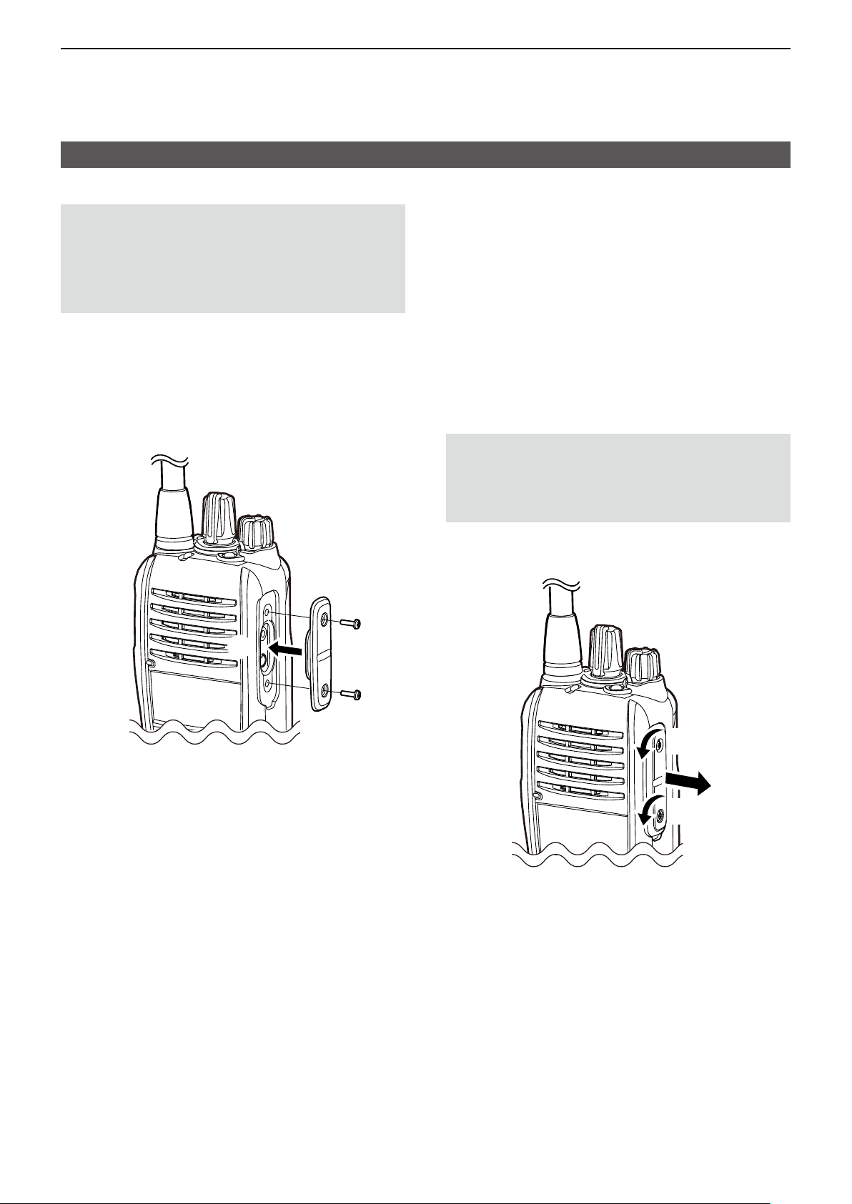
D Jack cover
CAUTION:
connector cover or optional equipment attached�
The transceiver meets IP67/IP55/IP54 requirements
for dust-tight and waterproof protection only when
the connector cover or the HM-168LWP, HS-94LWP,
or HS-95LWP is attached�
Attaching:
1� Place the jack cover over the speaker-microphone
jack� (q)
2� Insert and tighten the screws� (w)
DO NOT
use the transceiver without the
w
Detaching:
1� Unscrew the screws using a Phillips screwdriver�
(
)
z
2� Detach the jack cover� (x)
CAUTION: DO NOT detach the jack cover when
optional equipment is going to be used� Otherwise
the terminals of the speaker microphone jack may be
shorted by a metal object, or become rusty by water
intrusion� This could damage the transceiver�
q
w
z
x
z
1-3
Page 6

Section 2
PANEL DESCRIPTION
Front, top and side panels ����������������������������������������������������������������������2-2
D Status indicator �������������������������������������������������������������������������������2-2
D About the Software Key functions ���������������������������������������������������2-2
Function display��������������������������������������������������������������������������������������2-3
Status indicator ���������������������������������������������������������������������������������������2-4
Assignable Software Key functions ��������������������������������������������������������2-6
2-1
Page 7
2
PROGRAMMING SOFTWARE
PANEL DESCRIPTION
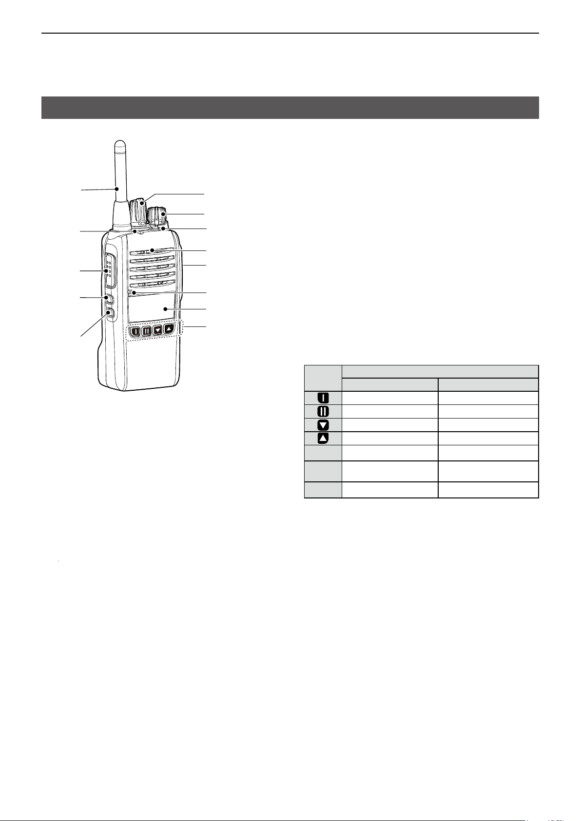
Front, top and side panels
Antenna
Status
indicator
[PTT]
[Up]
[Down]
[Rotary Selector]
[VOL]
[TOP]
Speaker
Speaker
microphone jack
Microphone
Function display
Programmable
function Keys
D Status indicator
• Lights red: Transmitting�
• Lights green: Receiving or squelch is open�
• Lights or blinks orange
: A matching signal is received,
depending on the presetting�
• Slowly blinks green: The battery should be charged�
• Quickly blinks green: The battery is exhausted�
L Refer to the Status indicator section�(pp�2-4 ~2-5)
D About the Software Key functions
You can assign the functions described below to
Programmable function Keys, [Up], [Down], and [TOP]
by using the CS-F29SDR
(purchase separately)�
The following Software keys are assigned as defaults:
Assigned Software Key
Analog Digital
Monitor Clear
S-Ring/C-Ring Call/C-Ring
CH Down/Zone Down CH Down/Zone Down
CH Up/Zone Up CH Up/Zone Up
[Up] Code Code/Select
[Down]
[Top]
Lock/Favorite CH
Rewrite
A-Ring A-Ring
Lock/Favorite CH
Rewrite
2-2
Page 8
2
PANEL DESCRIPTION
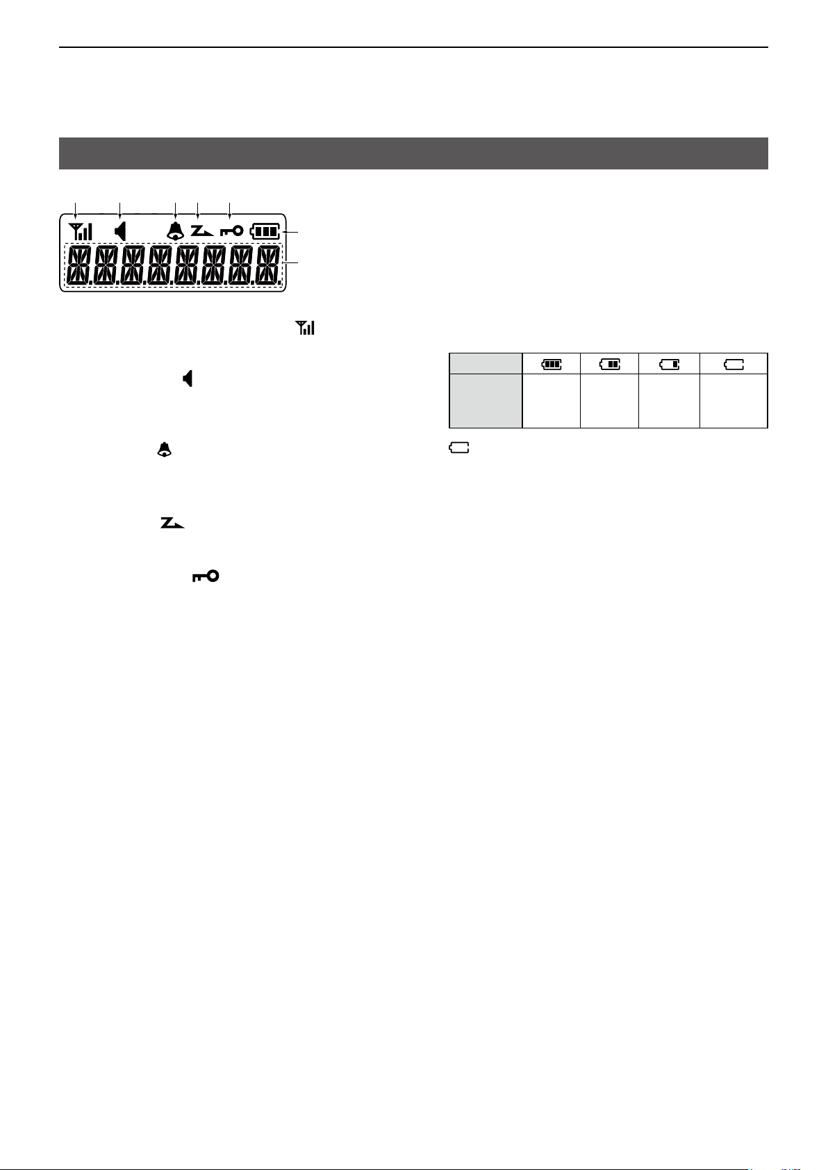
Function display
1 2 34 5
6
7
1SIGNAL STRENGTH INDICATOR
Displays the relative receive signal strength level�
2AUDIBLE ICON
Displayed when the channel is in the ‘Audible’
(unmuted) mode�
3BELL ICON
Displayed when a matching signal is received,
depending on the presetting�
4SCAN ICON
Displayed or blinks while scanning�
5KEY LOCK ICON
Displayed when the Key Lock function is ON�
6BATTERY INDICATOR
Displays the remaining battery charge�
Indication
Battery
Status
blinks when the battery is exhausted�
7ALPHANUMERIC READOUT
Displays the selected Zone number, channel
number, and, if entered, the channel name�
Full Mid
Charging
required
Battery
exhausted
2-3
Page 9
2
GGGGGGGGGGGGGGG
GGG
G
GGGGGGGGG
PANEL DESCRIPTION
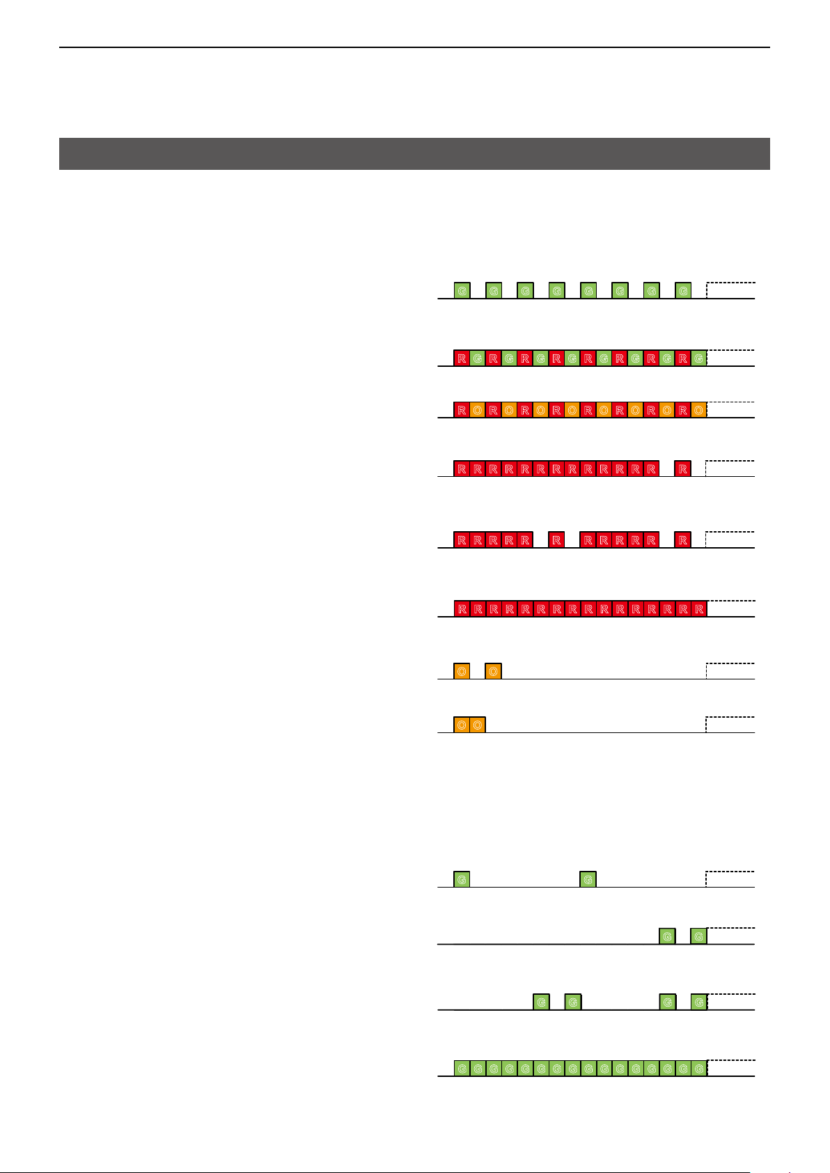
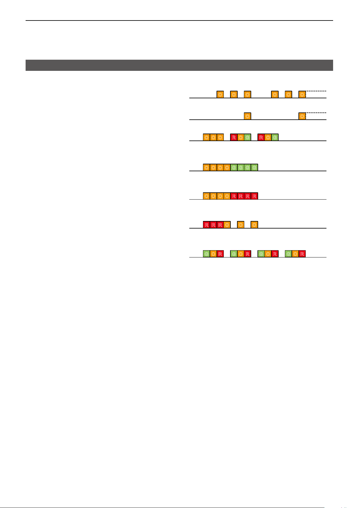
Status indicator
The Status indicator indicates the status of various
parameters of the transceiver, as described below�
(Reference: R=Red, G=Green, O=Orange)
• Programming:
Blinks while reading or writing data�
• Programming Error:
Continuously blinks green and red if programming
fails�
• Channel Error:
Continuously blinks red and orange when you select
a blank channel, or an unlocked channel�
• TX Low Battery 1:
Blinks while detecting a low battery while
transmitting�
G G G G G G G G
R G R G R G R G R G R G R G R G
R O R O R O R O R O R O R O R O
R R R R R RR R R R R R R R
• TX Low Battery 2:
Blinks while detecting a very low battery while
transmitting�
• TX:
Lights while transmitting�
• Bell (Blink):
Blinks about twice every second, when the preset
signal* is received�
• Bell (ON):
Blinks about once every second, when the preset
signal* is received�
* Depending on the “Bell” setting, the Status indicator blinks:
• When a Break-in is received�
• When a Status call that includes a matching status
number is received�
• When a Call Setup is received in the dPMR™ operation�
• Scan:
Blinks green while scanning for a channel with a
signal�
R R R R R R R R R R R R
R R R R R R R RR R R R R R R R
O O
O O
G G
• Low Battery 1
Blinks slowly when you should charge the battery
G
soon�
• Low Battery 2
G G
G
Blinks fast when you should charge the batterysoon�
• RX:
Lights green while receiving a signal�
G G G G G G G GG G G G G G G G
► Continued on the next page
2-4
Page 10
2
PANEL DESCRIPTION
Status indicator (Continued)
• CH Access:
Blinks orange while making a call�
• Audible:
Blinks orange while in the Audible mode�
• Power ON:
Lights orange, then blinks red, orange, and green
twice at transceiver startup�
• Success:
Blinks orange and green repeatedly when your call
was successful�
• Failure:
Blinks orange and red repeatedly when your call
failed, or it was refused�
O O O O O O
O O
O O O R O GR O G
OO OO G GGG
O O OO RRR R
• TX Error:
Blinks when transmission is inhibited (Lockout, TX
Inh, or TOT Penalty timer)�
• Emergency, Siren:
Blinks while the Alert-Ring operation, Lone Worker
function, or Siren function is activated�
R R R O O O
ROG ROG ROG ROG
2-5
Page 11

2
PANEL DESCRIPTION
Assignable Software Key functions
Category Assignable function Reference Digital (dPMR446) Analog
Channel /
Scan
Signaling /
Call
Functions
Null p� 2-7
Clear p� 2-7
Auto CH p� 2-7
CH Up, CH Down p� 2-7
CH Up/Zone UP
CH Down/Zone Down
Favorite CH Rewrite p� 2-7
Monitor p� 2-7
Scan Start/Stop p� 2-7
A-Ring p� 2-8
Break p� 2-8
C-Ring p� 2-8
Call p� 2-8
Call/C-Ring p� 2-8
Code p� 2-8
Code/Select p� 2-8
S-Ring p� 2-8
S-Ring/C-Ring p� 2-8
Select p� 2-8
Announce p� 2-9
AquaQuake p� 2-9
Light p� 2-9
Lock p� 2-9
Lock/A-ring p� 2-9
Lock/Favorite CH Rewrite p� 2-9
Lone Worker p� 2-9
My Name p� 2-9
Siren p� 2-9
Sp� Func 1/2 p� 2-9
Surveillance p� 2-9
User Set Mode p� 2-9
p� 2-7
✓ ✓
✓ ✓
✓ ✓
✓ ✓
✓ ✓
✓ ✓
✓ ✓
✓ ✓
✓ ✓
✓
✓ ✓
✓
✓
✓ ✓
✓
N/A
N/A
✓
✓ ✓
✓ ✓
✓ ✓
✓ ✓
✓ ✓
✓ ✓
✓ ✓
✓ ✓
✓ ✓
✓ ✓
✓ ✓
✓ ✓
N/A
N/A
N/A
N/A
✓
✓
N/A
✓: Applicable
N/A: Not Applicable
2-6
Page 12

2
PANEL DESCRIPTION
Assignable Software Key functions (Continued)
Null
No function�
Clear
z Push to return to the inaudible mode and
automatically send a Clear Down signal� (Digital
operation only)
L This key is valid only in the audible mode�
z Push to return to the standby mode when the
application selection mode menu is displayed�
Category: Channel/Scan
Auto CH
z Push to automatically search a clear channel
during�
CH Up, CH Down
z Push to select an operating channel�
z After pushing a Software Key, push to select an
option, setting, and so on�
z Push to select an option setting after pushing a
programmable Key�
CH Up/Zone Up, CH Down/Zone Down
z Push to select a Memory channel, while in the
Standby mode�
z Hold down for 1 second to select a Zone, while in
the Standby mode�
TIP: What is a “Zone”?
Certain channels are grouped together and
assigned to a Zone according to their intended use�
For example, Analog channels ‘Station 1’ and
‘Station 2’ are assigned to an “Analog” Zone, and
Digital channels ‘Station 3’ and ‘Station 4’ are
assigned to a “Digital” Zone�
Favorite CH Rewrite
Hold down for 1 second to update the Favorite channel�
L See page 3-3 for details�
Monitor
z Hold down to unmute the channel� (Audible mode)
z Push to enter the Inaudible mode�
z Activates the following function on each channel,
depending on the presetting�
z Depending on the presetting, hold down for 1
second to cancel the scan�
NOTE: The audible (unmuted) mode may
automatically return to the Inaudible (muted)
mode, after the preset time period ends�
Scan Start/Stop
z Push to start or cancel a Scan�
L When a scan started with the Power ON Scan or Auto
Scan function, pushing this key pauses the scan� The
paused scan resumes after the preset time period has
passed�
z While a scan is paused by detecting a signal,
hold down for 1 second to temporarily remove the
channel from the scan group�
After the scan is canceled, the removed channel
automatically returns to the scan group�
2-7
Page 13

2
PANEL DESCRIPTION
Assignable Software Key functions (Continued)
Category: Signaling/Call
A-Ring
Hold down to transmits the alert signal to other
stations�
• “ALERT” is displayed�
L See page 4-2 for details
Break
The Break-in request call announces to the other
stations on the channel that the user wants to break
into the current communication in the group�
The transceiver waits for the current communication to
end, and then sends the call�
z Push to send a Break-in request call�
L See pages 6-3 and 6-4 for details�
C-Ring
Hold down to make a Call-Ring call�
• The ringer sounds while holding down [C-Ring], depending
on the setting�
• The same ringer sounds from your group members’
speakers�
Call
z Push to transmit the Call Setup to Common ID�
z Push to transmit the Status to Common ID�
Call/C-Ring
z Push to enter the Call function�
z Hold down to make a Call-Ring call to the desired
station with the ringer melodies�
L You can select the 16 types of the melody patterns in
the Call-Ring Pattern function�
Code/Select
z Push to enter the Code Select mode which is the
Common ID for the Digital mode�
z Hold down for 1 second to turn the Status Select
mode from the TX Status function for the Digital
mode�
S-Ring
A transceiver that receives a Smart-Ringer call from
another transceiver sounds the Ringer melody�
Also, the called transceiver sends an acknowledgment
signal back to caller transceiver�
z Push to make a Smart-Ring call�
S-Ring/C-Ring
z Hold down to make a Call-Ring call�
z Push to make a Smart-Ring call�
Select
z Push to select the TX Status Message in the
Standby mode�
L You can select a Status Message as described below�
1� Pushing [Select] to display the Status Message
Selection screen, and then select a Status
Message using [CH Up], [CH Down],
[CH Up/Zone Up], [CH Down/Zone Down]�
2� Selects the desired Status Message then push
[Call] to transmit a call�
Code
In the Analog mode
1� Push to enter the CTCSS tone and DTCS code
Selection mode�
2� Then push [CH Up], [CH Down],
[CH Up/Zone Up], or [CH Down/Zone Down] to
select a CTCSS tone or DTCS code�
3� After selecting, push this key again to set�
z Hold down for 1 second to start the Find Tone
Select function to scan for the CTCSS tone and the
DTCS code�
In the Digital mode
1� Push to select the Common ID Selection mode�
2� Push [CH Up], [CH Down], [CH Up/Zone Up],
or [CH Down/Zone Down] to select a desired
Common ID�
3� After selecting, push this key again to set�
2-8
Page 14

2
PANEL DESCRIPTION
Assignable Software Key functions (Continued)
Category: Functions
Announce
Push to turn the Channel Announce function ON or
OFF�
L You can also turn ON this function by holding down [ ]
when you turn ON the transceiver�
AquaQuake™
While holding down this key, the AquaQuake water
draining function removes water from the speaker grill
by vibrating the internal speaker�
L Water in the speaker grill may mufe the sound coming
from the speaker�
NOTE:
• After the specied period of time, this function
automatically stops, even if a user continues to hold
down this key�
• This key works with only the internal speaker�
L You can also turn ON this function by holding down
[Up] and [ ] when you turn ON the transceiver�
Light
Push to turn ON the backlight for about 5 seconds,
even if the backlight setting is OFF�
Lock
Hold down for 1 second to turn the Key Lock function
ON or OFF�
L All assignable keys except the following are electronically
locked: [Lock], [Lock/A-Ring],
[Lock/Favorite CH Rewrite], [Lone Worker], [Monitor],
[Call], [Light], [Siren], [Surveillance], [A-Ring], [Clear],
[Call/C-Ring], [Sp� Func 1], [Sp� Func 2] and [PTT]�
You can also make or receive calls, or turn the transceiver
ON or OFF, while the Key Lock function is ON�
L When the Lock function is ON, the Lock icon is displayed�
My Name
Push to display the programmed “My Name�”
Siren
Hold down to emit a siren sound from the speaker
to let surrounding people know that you are in an
Emergency situation�
L The siren will sound continuously until the transceiver is
turned OFF�
Sp. Func 1, Sp. Func 2
Sp� Func 1 and Sp� Func 2 are reserved for PC
commands�
Surveillance
Push to turn the Surveillance function ON or OFF�
When this function is turned ON, beeps do not sound,
and the backlight and the status indicator do not light,
even when a signal is received, or a key is pushed�
User Set Mode
z Hold down for 1 second to enter the User Set mode�
The User Set mode is used to change settings,
without using a PC�
L Hold down for 1 second again to exit the User Set
mode�
z In the User Set mode, momentarily push this key to
select an item, and then push [CH Up], [CH Down],
[CH Up/Zone Up], or [CH Down/Zone Down] to
change the value or setting�
NOTE: To use the [User Set Mode] and [CH Up],
[CH Down], [CH Up/Zone Up], or
[CH Down/Zone Down] must be assigned to
assignable keys using the programming software�
Lock/A-Ring
z Push to enter the Lock function�
z Hold down for 1 second to turn the A-Ring function�
Lock/Favorite CH Rewrite
z Push to enter the Lock function�
z Hold down for 1 second to turn ON the Favorite CH
Rewrite function�
Lone Worker
Push to turn the Lone Worker function ON or OFF�
L If no operation occurs during a specied period, the Lone
Worker function automatically makes the transceiver
enter the Alert-Ring mode�
NOTE: To use the Lone Worker function, set the
related settings using the programming software�
L See page 4-2 for details�
2-9
Page 15

Section 3
BASIC OPERATION
Turning ON the transceiver ��������������������������������������������������������������������3-2
D Turning ON the transceiver �������������������������������������������������������������3-2
D Adjusting the audio level �����������������������������������������������������������������3-2
D Entering the password ��������������������������������������������������������������������3-2
Selecting a Zone�������������������������������������������������������������������������������������3-3
D Selecting a Zone �����������������������������������������������������������������������������3-3
Selecting a channel ��������������������������������������������������������������������������������3-3
D Selecting an operating channel ������������������������������������������������������3-3
D Favorite CH function �����������������������������������������������������������������������3-3
Call procedure ����������������������������������������������������������������������������������������3-4
Receiving and transmitting ���������������������������������������������������������������������3-5
D Transmitting notes ��������������������������������������������������������������������������3-5
3-1
Page 16

BASIC OPERATION
3
Turning ON the transceiver
D Turning ON the transceiver
NOTE: Before using the transceiver for the fi rst time,
the battery pack must be fully charged for optimum
life and operation� See the BASIC MANUAL for
details�
Rotate [VOL] to turn ON the transceiver�
• The battery voltage or the opening text may be
displayed, depending on the presetting.
D Adjusting the audio level
When receiving a call, rotate [VOL] to adjust the audio
output level�
[Rotary Selector]
[VOL]
D Entering the password
If the transceiver is preset for a Power ON Password,
“PASSWORD” is displayed when turning ON the
transceiver�
In that case, enter the password.
1� Push the appropriate keys to enter numbers, as
described below�
Key
Number
2� After entering the correct password, the
transceiver automatically displays the Standby
screen�
NOTE: If the transceiver does not display the
Standby screen after entering the password, the
entered code may be incorrect� Turn OFF the
transceiver, then ON again to reenter the password.
0
5
1
6
2
7
[Down]
3
8
4
9
Standby screen (Example)
3-2
Page 17

BASIC OPERATION
3
Selecting a Zone
D Selecting a Zone
TIP: What is a “Zone”?
Certain channels are grouped together and assigned
to a Zone according to their intended use�
For example, Analog channels ‘Station 1’ and
‘Station 2’ are assigned to an “Analog” Zone, and
Digital channels ‘Station 3’ and ‘Station 4’ are
assigned to a “Digital” Zone�
To select a Zone:
z Hold down [CH Up/Zone Up] or
[CH Down/Zone Down]�
• The selected Zone number or name is briey
displayed, and then returns to the Standby screen.
Selecting a channel
D Selecting an operating channel
To select a channel:
z Rotate [Rotary Selector] to select the Favorite CH�
z Push [CH Up], [CH Down], [CH Up/Zone Up], or
[CH Down/Zone Down]�
D Favorite CH function
You can assign Memory Channels as Favorite
Channels, for up to 16 channels to the Rotary Selector.
The Favorite Channel function enables you to quickly
select channels using the Rotary Selector�
1� Set to the desired Rotary Selector position to the
channel that you want to update�
2� Move to a current channel that you want to rewrite
as a Favorite Channel by pushing [CH Up],
[CH/Down], [CH Up/Zone Up], or
[CH Down/Zone Down]�
3� Hold down [Favorite CH Rewrite] and rewrite
the new Favorite Channel to the desired Rotary
Selector's position�
• “FAVORITE” is displayed when the setting is
successful.
3-3
Page 18

BASIC OPERATION
Non-selective calling
3
Call procedure
When your system uses tone signaling, a call
procedure may be necessary prior to voice
transmission� The tone signaling employed may be
a selective calling system, which enables you to call
only specifi c stations, and prevents unwanted stations
from contacting you�
CTCSS, DTCS, Common ID must be the same on all
of your group transceiver to uses tone signaling�
1� Select a channel according to your system
operator’s instructions.
This may not be necessary, depending on the
presetting�
2�
Push [S-Ring], [S-Ring/C-Ring], [Call] or
[Call/C-Ring]�
3� After transmitting, the remainder of your
communication can be carried out in the normal
way�
Selective calling
Non-selective calling
3-4
Page 19

BASIC OPERATION
3
Receiving and transmitting
Receiving:
1� Turn ON the transceiver. (p. 3-2)
2� Select a channel. (p. 3-3)
3� When receiving a call, rotate [VOL] to adjust the
audio output level to a comfortable listening level�
Transmitting:
1� Wait for the channel to become clear to avoid
interference�
2� While holding down [PTT], speak at your normal
voice level�
3� Release [PTT] to receive�
IMPORTANT: To maximize the readability of your
signal�
1. Pause briey after pushing [PTT].
2. Hold the microphone 5 to 10 cm from your mouth,
then speak at your normal voice level�
D Transmitting notes
Transmit inhibit function
The transceiver has several inhibit functions which
restrict transmission under the following conditions:
• The channel is in the Inaudible mode (“ ”: Audible
icon is not displayed.)
• The channel is busy. However, depending on the
presetting, you can transmit when a call is received
that includes a non-matching (or matching) CTCSS
(DTCS), Common ID.
• The selected channel is a ‘receive only’ channel.
Time-Out Timer
If continuous transmission exceeds the preset
Time-Out Timer time, transmission is cut off.
Penalty timer
After transmission is cut off by the Time-Out Timer,
transmission is further inhibited for a preset penalty
period of time�
3-5
Page 20

Section 4
ADVANCED OPERATION
Alert-Ring call �����������������������������������������������������������������������������������������4-2
D Transmitting an Alert-Ring call ��������������������������������������������������������4-2
Sounding a Siren ������������������������������������������������������������������������������������4-3
AquaQuake™ Water Draining function ��������������������������������������������������4-3
Scan Operation���������������������������������������������������������������������������������������4-3
D Scan types ��������������������������������������������������������������������������������������4-3
4-1
Page 21

ADVANCED OPERATION
[A-Ring]
[KEY]
4
Alert-Ring call
D Transmitting an Alert-Ring call
When the transceiver enters the Alert-Ring mode, a
countdown starts� The transceiver counts down during
the Repeat Timer set time�
Before the Repeat Timer set time expires, the
transceiver transmits an Alert-Ring once or repeatedly�
L The transceiver automatically transmits a
repeat Alert-Ring call until a user turns OFF the
transceiver or until holding down [A-Ring] or
[Lock/A-Ring]�
The transceiver enters the Alert-Ring mode through
the following functions:
• The [A-Ring] key function
L If holding down [A-Ring] or [Lock/A-Ring], the Alert-
Ring mode is canceled�
Enters the
Alert-Ring mode.
Repeat Timer
[A-Ring]
Sends an
Alert-Ring call.
TX TimerTX Timer
[A-Ring]
• The Lone Worker function
1� When no operation occurs, the ON Timer presets
time�
2� When the transceiver is put into the Alert-Ring
mode by the Lone Worker function, the Reminder
Timer starts�
L If a user pushes any key before the Reminder
Timer set time expires, the Alert-Ring mode is
canceled�
3� After the Reminder Timer period ends, the
transceiver transmits an Alert-Ring call once or
repeatedly�
4� When after period time of TX Timer, automatically
starts the count down beep to start the Alert-Ring
function�
Enters the
Alert-Ring mode.
[PTT][PTT]
Operation
ON Timer
No operation
is detected.
Time
Reminder Timer
Sends an
Alert-Rig call.
TX Timer
If pushing any key
during the Reminder
Timer time, the
Alert-Ring mode is
canceled.
Repeat Timer
TX Timer
Operation
Time
4-2
Page 22

ADVANCED OPERATION
Repeatedly scans
current Zone's channels
that the Scan function is
ON.
Repeatedly scans all
channels that the Scan
function is ON on the
Memory CH.
Zone Scan mode
All Scan mode
ch 1
Zone 1
Zone 2
ch 2 ch 16
ch 2
ch 16Zone 3
ch 1
Zone 4
Non select
channel
ch 16
ch 1 ch 2 ch 3
ch 4
ch 5
ch 6ch 15
Non select
channel
4
Sounding a Siren
Hold down [Siren] to emit a siren sound from the
speaker to let surrounding people know that you are in
an Emergency situation�
The siren will sound continuously until the transceiver
is turned OFF�
AquaQuake™ Water Draining function
By vibrating the speaker cone, the AquaQuake Water
Draining function clears water from the speaker grill to
maintain clear audio�
1� Hold down [AquaQuake] to turn ON the
AquaQuake water draining function�
L You can also turn ON this function to rotate
[VOL] to turn ON the transceiver, while holding down
[Up] and [ ]�
• A low frequency vibration is generating to remove
water from the speaker grill�
• Waterinthespeakergrillmaymufethesound
coming from the speaker�
2� Release the keys to turn OFF the function�
NOTE:
• Afterthespeciedperiodoftimeexpires,this
function automatically stops, even if a user
continues to hold down these keys�
• These keys works for only the internal speaker�
Scan Operation
D Scan types
Scanningisanefcientwaytolocatesignalsquickly
over all channel�
Selecting Zone Scan mode speeds up the scanning
interval�
In addition, repeatedly scanning all zone channels or
selected zone channels can be selected�
1� Hold down [Scan Start/Stop] to select the Scan
mode�
2� Push [CH Up], [CH Down], [CH Up/Zone Up], or
[CH Down/Zone Down] to select the scanning
lists�
3� Push [Scan Start/Stop] to return to the standby
mode�
4-3
Page 23

Section 5
USER SET MODE
User Set mode description ���������������������������������������������������������������������5-2
D Operation in the User Set mode ����������������������������������������������������5-2
User Set mode items ������������������������������������������������������������������������������5-3
D Ringer Type of Digital Ringer and Smart Ringer �����������������������������5-6
5-1
Page 24
USER SET MODE
5
User Set mode description
The user can enter the “User Set Mode” to customize
certain transceiver settings without using the
programming software�
D Operation in the User Set mode
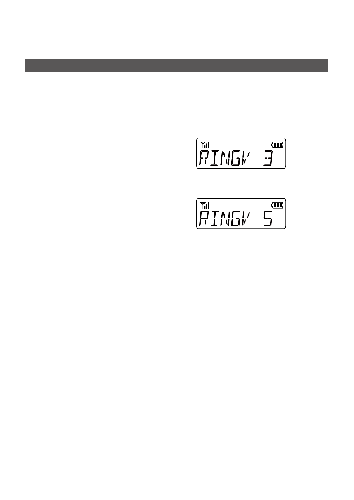
Example: Changing the Ringer level from 3 to 5�
1� Hold down [User Set Mode] for 1 second to enter
the User Set mode�
2� Push [User Set Mode] to select an item�
(Example: Selecting Ringer (RINGV))
3� Push [CH Up], [CH Down], [CH Up/Zone Up], or
[CH Down/Zone Down] to select an option�
(Example: Selecting Level 5)
• The selected option is automatically set�
4� Hold down [User Set Mode] for 1 second to return
to the Standby screen�
5-2
Page 25

USER SET MODE
5
User Set mode items
Item Description Display Reference
Backlight
Beep
Beep Level
Ringer Level
SQL Level (Squelch Level) Sets the squelch level� SQL p� 5-4
AF Min Level (AF Minimum Level)
Mic Gain (Microphone Gain)
VOX
VOX Gain
VOX Delay
Battery Voltage
Signal Moni (Signal Monitor) Select whether or not to sound a ringer while making
Call-Ring Pattern
Digital Ringer
Smart Ringer
Ringer Timer
Code Type
Power Save
Lone Worker
Sets the Key Backlight status� LIGT p� 5-4
Turns the key-touch beeps ON or OFF� BEEP p� 5-4
Sets the beep and announce output level� BEEPV p� 5-4
Sets the Ringer output level� RINGV p� 5-4
Sets the minimum audio output level� AFMIN p� 5-4
Sets the microphone sensitivity� MIC p� 5-4
Turns the VOX function ON or OFF� VOX p� 5-4
Sets the VOX gain� VGAIN p� 5-4
Sets the VOX Delay� VDLY p� 5-4
Displays the battery voltage� BATT p� 5-4
SMON p� 5-4
a Call-Ring call or an Alert-Ring call�
Sets the Call-Ring Pattern� C�RIG p� 5-4
Sets the ringer type when a Call request is received� D�RIG p� 5-4
Sets the ringer type when a Smart-Ringer is received�
Sets the Ringer Timer for the Auto CH function� RTIM p� 5-4
Sets the display format in the CTCSS tone or DTCS
code selection mode�
Set the Power Save function ON or OFF� PSAV p� 5-5
Turns the Lone Worker function ON or OFF� LONE p� 5-5
S�RIG p� 5-4
TYPE p� 5-5
5-3
Page 26

USER SET MODE
5
User Set mode items (Continued)
Backlight
Sets the Backlight status�
• OFF: Turns OFF the backlight�
• OFF Auto: When pushing any key (except [PTT]),
the backlight automatically turns ON for
5 seconds�
• OFF Auto2: When pushing any key (except [PTT]),
or when changing the displayed
contents of the LCD, the backlight
automatically turns ON for 5 seconds�
• ON: The backlight is turned ON all the time�
Beep
Turns the key-touch beeps ON or OFF�
Beep Level
Sets the beep and announce output level�
• Range: 1 ~ 5, or 1 (Linked) ~ 5 (Linked)�
When setting the Linked option, the beep and
announce output levels are adjusted with [VOL]�
Ringer Level
Sets the Ringer output level�
• Range: 1 ~ 5, or 1 (Linked) ~ 5 (Linked)�
When setting the Linked option, the ringer level is
adjusted with [VOL]�
SQL Level (Squelch Level)
Sets the squelch level�
• Range: 0 (open) ~ 9 (tight)
AF Min Level (AF Minimum Level)
Sets the minimum audio output level�
This function sets the minimum audio output level and
[VOL] cannot adjust the audio lower than the set level�
• Range: 0 ~ 255
VOX Gain
Sets the VOX gain�
The VOX function automatically switches between
receive and transmit by detecting sounds�
Higher values make the VOX function more sensitive
to sounds�
• Range: 1 ~ 10
VOX Delay
Sets the period of time the transceiver continues
transmitting after the user stops speaking, and then
the VOX switches to receive�
• Range: 0�5 ~ 3�0 seconds
Battery Voltage
Sets whether or not to display the battery voltage
when turning ON the transceiver�
Signal Moni (Signal Monitor)
Select whether or not to sound a ringer while making
a Call-Ring call or an Alert-Ring call�
• OFF: The ringer does not sound while making a
Call-Ring call or an Alert-Ring call�
• ON: The ringer sounds while making a Call-Ring
call or an Alert-Ring call�
Call-Ring Pattern
Selects the Call-Ring Pattern to call by placing a
melody on the transmission modulation�
L The Call-Ring Pattern function has 16 types of Melody
pattern for use with the Call-Ring function�
Digital Ringer
Sets the ringer type for when a Call request is
received�
L See pages 5-6 ~ 5-8 for details of Ringer Type�
Mic Gain (Microphone Gain)
Sets the microphone sensitivity�
• Range: 1 (low sensitivity) ~ 4 (high sensitivity)
VOX
Turns the VOX function ON or OFF�
NOTE: To use the function, a headset and a VOX
converter cable are required (purchase separately)�
Smart Ringer
Sets the ringer type for when a Smart-Ringer is
received�
L See pages 5-6 ~ 5-8 for details of Ringer Type�
Ringer Timer
Sets the Ringer Timer for the Auto CH function�
The Ringer timer denes the transmit time that the
Auto CH function is ON�
After the set time has passed, the Auto CH function
will stop transmitting and restart the scan according to
the Auto Reset Timer setting�
• Range: 0 ~ 16 seconds
5-4
Page 27

USER SET MODE
5
User Set mode items (Continued)
Code Type
Sets the display format in the CTCSS tone or DTCS
code selection mode�
• Code: Displays CTCSS tone or DTCS code�
• Num: Displays CTCSS or DTCS CH No�
Power Save
Sets the Power Save function ON or OFF�
This function reduces the current drain and conserves
battery power by deactivating the receiver circuit
according to the Power Save start timers�
The Power Save function automatically starts a power
save action and reduces the consumption of the
battery charge�
• OFF: Turns OFF the function�
• Analog: To activate in the Analog mode�
• Digital: To activate in the Digital mode�
• Both: To activate in the Analog and Digital mode�
Lone Worker
Sets whether or not to automatically enter the Alert-Ring
mode when no operation occurs during the set period of
time�
5-5
Page 28
USER SET MODE
50 mSec
50 mSec
50 mSec 50 mSec
50 mSec
40 mSec 40 mSec 40 mSec 40 mSec 40 mSec 40 mSec
40 mSec
120 mSec
5
User Set mode items (Continued)
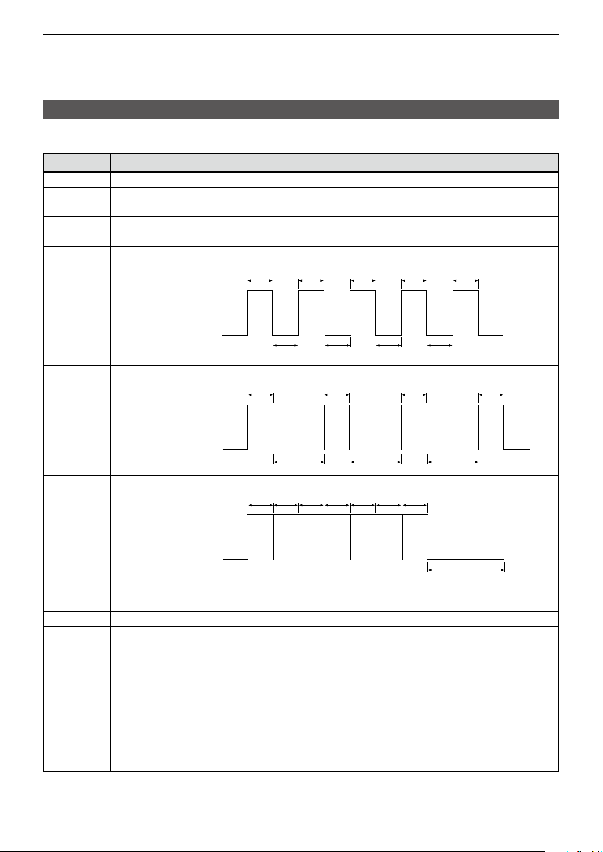
D Ringer Type of Digital Ringer and Smart Ringer
Options Ringer Type Description
- Null
OFF OFF
1 Pi
2 PiPi
3 Pi-
4
PiPiPiPiPi Five high rings sound once�
The state of the ringer does not change�
Turns OFF the ringer�
One high ring sounds once�
Two high rings sound once�
One high long ring sounds once�
5 PiRo1
6 PiRo2
1*
2*
3*
Pi (Repeat) One high ring repeatedly sounds during the ringer repeat timer period�
PiPi (Repeat) Two high rings repeatedly sound during the ringer repeat timer period�
Pi- (Repeat) One high long ring sounds during the ringer repeat timer period�
4* PiPiPiPiPi
The following ringer pattern sounds only once�
The following ringer pattern sounds twice�
Five high rings sound during the ringer repeat timer period�
(Repeat)
5*
PiRo1 (Repeat) One high and one low rings repeatedly sound during the ringer repeat timer
period�
6*
PiRo2 (Repeat) One high and one low rings rapidly and repeatedly sound during the ringer
repeat timer period�
7~22 Melody1 to
The selected ringer pattern between Melody 1 and Melody 16 sounds�
Melody16
7*~22*
Melody1 (Repeat)
to Melody16
(Repeat)
The selected ringer pattern between Melody 1 and Melody 16 sounds during the
ringer repeat timer period�
High 1
Freq
50 mSec
High 1
Freq
High 2
Freq
High 1
Freq
50 mSec 50 mSec 50 mSec
50 mSec 50 mSec 50 mSec
High 2
Freq
High 1
Freq
High 1
Freq
Low Freq
100 mSec 100 mSec 100 mSec
High 1
Freq
High 1
Freq
Low Freq
High 2
Freq
OFFOFFOFF
High 1
Freq
High 1
Freq
High 1
Freq
High 2
Freq
50 mSec
High 1
OFF OFF
Freq
OFF
High 1
Freq
Low Freq
► Continued on the next page
5-6
Page 29

USER SET MODE
50 mSec
50 mSec
50 mSec 50 mSec
50 mSec
50 mSec
50 mSec
50 mSec 50 mSec 50 mSec
50 mSec 50 mSec
60 mSec
60 mSec
60 mSec 60 mSec 60 mSec 60 mSec 60 mSec 60 mSec
60 mSec
60 mSec
60 mSec
60 mSec 60 mSec 60 mSec 60 mSec 60 mSec 60 mSec
60 mSec
60 mSec 60 mSec 60 mSec
60 mSec 60 mSec 60 mSec
5
User Set mode items (Continued)
Options Ringer Type Description
23 PiPiPi
Three high rings sound once�
24 PiPiPiPi
25 PiBu
26 BuPi
27 BuRoPi x3
28 PiRoBu x3
High 1
Freq
High 1
Freq
High 1
Freq
OFFOFFOFF
Four high rings sound once�
High 1
Freq
High 1
Freq
High 1
Freq
High 1
OFFOFFOFF
Freq
OFF
One high and one low rings sound once�
One low and one high rings sound once�
One low, one mid and one high rings sound three times�
Low
(Low Freq)
Mid
(High 1
Freq)
High
(High 2
Freq)
Low
(Low Freq)
Mid
(High 1
Freq)
High
(High 2
Freq)
(Low Freq)
Low
Mid
(High 1
Freq)
One high, one mid, and one low rings sound three times�
High
(High 2
Freq)
29 BuRoPi
30 PiRoBu
One low, one mid and one high rings sound once�
One high, one mid, and one low rings sound once�
(Low Freq)
High
(High 2
Freq)
Low
High
(High 2
Freq)
Mid
(High 1
Freq)
Mid
(High 1
Freq)
Mid
(High 1
Freq)
Low
(Low Freq)
High
(High 2
Freq)
Low
(Low Freq)
5-7
High
(High 2
Freq)
Mid
(High 1
Freq)
Low
(Low Freq)
High
(High 2
Freq)
(High 1
Freq)
(Low Freq)
Low
Mid
► Continued on the next page
Page 30

USER SET MODE
250 mSec 250 mSec
250 mSec
250 mSec 250 mSec
250 mSec
5
User Set mode items (Continued)
Options Ringer Type Description
31 Pi-Pi-Pi-Pi-
32 Bu-Ro-Pi-
Four high long rings sound once�
One low, one mid and one high long rings sound once�
33 Pi-Ro-Bu-
23*
24*
25*
26*
PiPiPi (Repeat) Three high rings sound during the ringer repeat timer period�
PiPiPiPi (Repeat)
PiBu (Repeat) One high and one low rings sound during the ringer repeat timer period�
BuPi (Repeat) One low and one high rings sound during the ringer repeat timer period�
27* BuRoPi x3
(Repeat)
28* PiRoBu x3
(Repeat)
29*
30*
BuRoPi (Repeat)
PiRoBu (Repeat)
31* Pi-Pi-Pi-Pi-
(Repeat)
32* Bu-Ro-Pi-
(Repeat)
33* Pi-Ro-Bu-
(Repeat)
Low
(Low Freq)
Mid
(High 1 Freq)
High
(High 2 Freq)
One high, one mid, and one low long rings sound once�
High
(High 2 Freq)
Mid
(High 1 Freq)
Low
(Low Freq)
Four high rings sound during the ringer repeat timer period�
One low, one mid and one high rings sound three times during the ringer repeat
timer period�
One high, one mid, and one low rings sound three times during the ringer repeat
timer period�
One low, one mid and one high rings sound during the ringer repeat timer
period�
One high, one mid, and one low rings sound during the ringer repeat timer
period�
Four high long rings sound during the ringer repeat timer period�
One low, one mid and one high long rings sound during the ringer repeat timer
period�
One high, one mid, and one low long rings sound during the ringer repeat timer
period�
5-8
Page 31

Section 6
dPMR™ OPERATION
Receiving a call ��������������������������������������������������������������������������������������6-2
D Receiving a call �������������������������������������������������������������������������������6-2
D Receiving a Status message ����������������������������������������������������������6-2
D Receiving a Break-in request call ���������������������������������������������������6-3
Transmitting a call
D General �������������������������������������������������������������������������������������������6-4
D Transmitting a call ���������������������������������������������������������������������������6-4
D Transmitting a Status message ������������������������������������������������������6-4
D Transmitting a Break-in request call �����������������������������������������������6-4
D Transmitting an Alert-Ring call ������������������������������������������������������� 6-4
����������������������������������������������������������������������������������6-4
6-1
Page 32

dPMR™ OPERATION
6
Receiving a call
D Receiving a call
When a call is received:
• Mute is released�
• The Status indicator lights green�
1� Hold down [PTT] to speak�
2� Release [PTT] to receive�
D Receiving a Status message
When a Status message is received:
• Beeps sound�
• The Status message is alternately displayed� “
” may be displayed or blink, depending on the
presetting�
• The Status Indicator may blink orange once or twice,
depending on the presetting�
Push [PTT] or any key to stop the display indication�
6-2
Page 33

dPMR™ OPERATION
Station
Station C
6
Receiving a call (Continued)
D Receiving a Break-in request call
When a Break-in call is received:
• The Status indicator lights green�
• Beeps sound�
• “BREAK” blinks on the display�
TIP: What is Break-in call?
The Break-in request call announces to the other
stations on the channel that the user wants to break
into the current communication in the group�
The transceiver waits for the current communication
to end, and then sends the call�
Example: Station A, B, and C are communicating
using the same Common ID�
Station A Station B
Push
[Break]
Station C
Wait
After Station A releases [PTT] (transmission is finished.)
Break! Break!
A Station B
Station C pushes [Break] to
transmit the break-in request
call while Station A is
transmitting.
Station A and B receive the
break-in request signal.
6-3
Page 34

dPMR™ OPERATION
6
Transmitting a call
You can make a call to a station that has the same
Common ID� Other digital mode transceivers on the
channel will not receive a call that does not match
their Common ID�
Before making a call, wait until the channel is clear to
avoid interference�
D General
The target ID (Common ID) are preset to a channel�
To make a call, you should select the desired channel
that your target station is set to�
D Transmitting a call
<Using [PTT]>
1� Select a channel as described below�
• Push [CH Up], [CH Down], [CH Up/Zone Up], or
[CH Down/Zone Down]�
• Rotate [Rotary Selector]�
D Transmitting a Status message
You can transmit a preset simple message� You
cannot transmit a voice signal at the same time�
1� Push [Select] or hold down [Code/ Select] to turn
the Status select mode�
2� Push [CH Up], [CH Down], [CH Up/Zone Up], or
[CH Down/Zone Down] to select a status�
3� Push [Call] to transmit a Status message�
D Transmitting a Break-in request call
1� While receiving a signal, push [Break]�
• “WAIT” is displayed�
• Pushing [Clear] or [Break] to cancel the call�
2� When the received signal is disappeared, the
break-in request call is automatically transmitted�
• “COMPLETE” is displayed when the break-in request
call is successful�
L The transceiver that received a Break signal blinks
“BREAK” on the display�
3� Push and hold [PTT], then speak into the
microphone at your a normal voice level�
2� Push [PTT] to transmit a call�
3� Hold down [PTT] to speak�
4� Release [PTT] to receive�
<Using the C-Ring function>
1� Select a channel as described below�
• Push [CH Up], [CH Down], [CH Up/Zone Up], or
[CH Down/Zone Down]�
• Rotate [Rotary Selector]�
2� Holding down [C-Ring], [Call/C-Ring] or
[S-Ring/C-Ring] while transmitting�
3� Hold down [PTT] to speak�
4� Release [PTT] to receive�
<Using the Call function>
1� Select a channel as described below�
• Push [CH Up], [CH Down], [CH Up/Zone Up], or
[CH Down/Zone Down]�
2� Push [Call] or [Call/C-Ring] to send a call request�
3� Hold down [PTT] to speak�
4� Release [PTT] to receive�
D Transmitting an Alert-Ring call
See “Alert-Ring Call” for details� (p�4-2)
6-4
Page 35

A7513-4EU
© 2019 Icom Inc. Mar. 2019
1-1-32 Kamiminami, Hirano-ku, Osaka 547-0003, Japan
 Loading...