

Page 1

OPERATING INSTRUCTIONS
dPMR446/PMR446 TRANSCEIVER
Iç-F29DR2
Page 2

INTRODUCTION
Previous view
Thank you for choosing this Icom product.
This product is designed and built with Icom’ s state of the art technology and craftsmanship. With proper care, it
should provide you with years of trouble-free operation.
IMPORTANT
FIRST, CAREFULLY READ THE BASIC MANUAL that is provided with the transceiver.
SAVE THESE OPERATING INSTRUCTIONS—
operating instructions for the IC-F29DR2 dPMR446/PMR446 TRANSCEIVER.
This transceiver includes some functions that are usable only when they are preset by your dealer. Ask your Icom
dealer or system operator for details.
These operating instructions contain additional important
TABLE OF CONTENTS
1 ACCESSORIES .................................................... 1
Attaching or detaching accessories ....................... 1
D Battery pack .............................................................1
D Belt clip .....................................................................1
D Jack cover ................................................................2
2 PROGRAMMABLE KEY FUNCTIONS................. 3
Programmable key functions ................................. 3
3 LED INDICATOR ................................................... 5
About the LED indicator ........................................ 5
4 SETTINGS ............................................................ 7
Setting the Beep function ...................................... 7
Setting the beep and announcement level ............ 8
5 dPMR™ OPERATION......................................... 15
Receiving and transmitting .................................. 15
D Receiving ...............................................................15
D Transmitting............................................................16
Break-in function ................................................. 17
D Receiving ...............................................................17
D Transmitting............................................................17
Status call ............................................................ 18
D Receiving ...............................................................18
6 OTHER FUNCTIONS .......................................... 19
Setting a scan type .............................................. 19
Tone Scan function .............................................. 20
Setting the Call-Ring ringer ................................... 9
Setting the ringer level ......................................... 10
Setting the microphone gain .................................11
Setting the squelch level ..................................... 12
Setting the VOX function ..................................... 13
Setting the VOX gain ........................................... 14
Icom, Icom Inc. and the Icom logo are registered trademarks of Icom Incorporated (Japan) in Japan, the United States, the United Kingdom,
Germany, France, Spain, Russia, Australia, New Zealand, and/or other countries.
dPMR and the dPMR logo are trademarks of the dPMR MoU Association.
All other products or brands are registered trademarks or trademarks of their respective holders.
i
Page 3
Battery release
b
r
Section 1
Previous view
ACCESSORIES
Attaching or detaching accessories
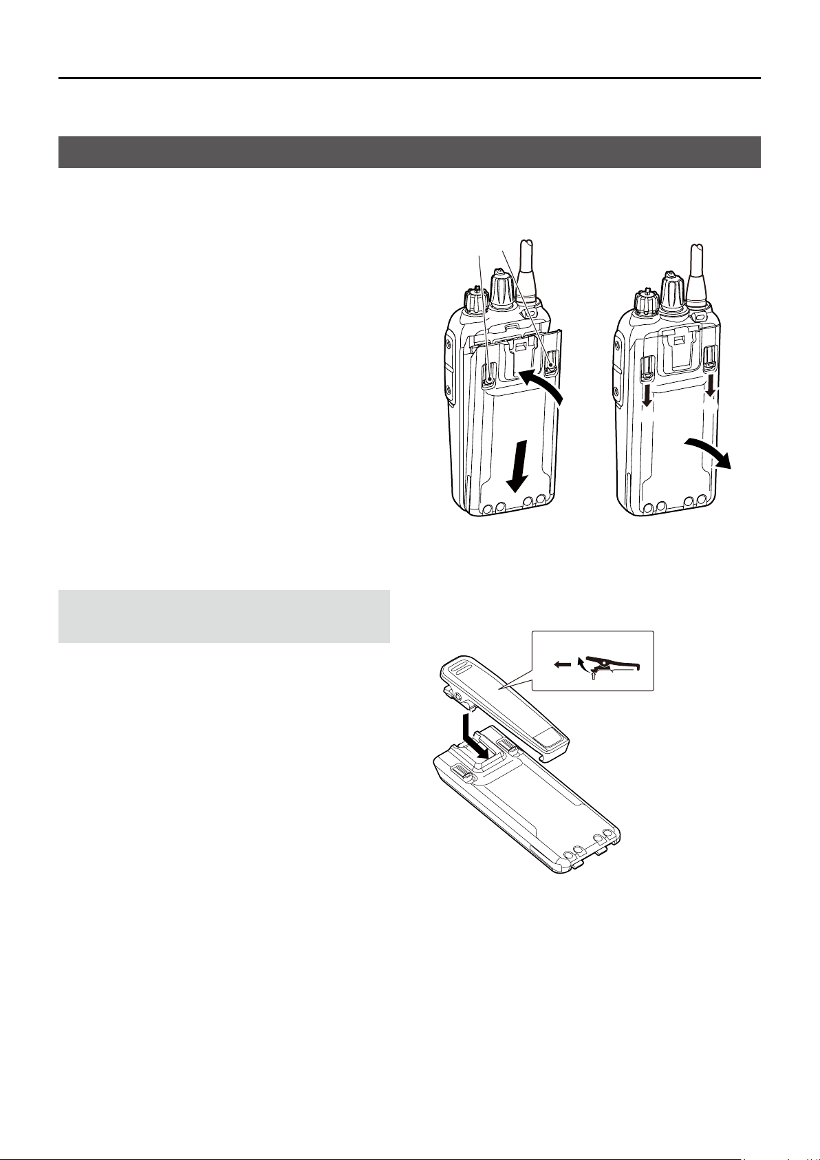
D Battery pack
Attach or detach the battery pack, as shown to the
right.
To attach To detach
To attach the battery pack:
1. Place the tabs on the bottom of the battery pack
into the slots at the bottom of the transceiver. (q)
2. Push the battery pack until the battery release
buttons make a ‘click’ sound. (w)
To detach the battery pack:
1. Push the battery release buttons in the direction
of the arrow, as shown to the right. (e)
2. The battery pack is then released, and you can
detach it. (r)
D Belt clip
NOTE: Before attaching or detaching the belt clip,
detach the battery pack from the transceiver, if it is
attached.
To attach the belt clip:
Slide the belt clip in the direction of the arrow until the
belt clip locks in place, and makes a ‘click’ sound. (q)
To detach the belt clip:
Lift the tab up (w), and slide the belt clip in the
direction of the arrow (e).
uttons
To attach
q
q
w
To detach
w
e
Ta b
e
e
1
Page 4
1
Previous view
ACCESSORIES
Attaching or detaching accessories (Continued)
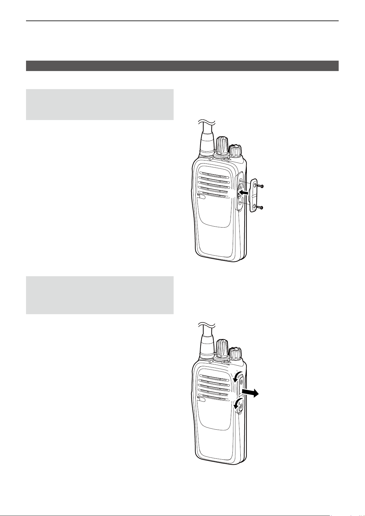
D Jack cover
NOTE: The transceiver meets IP67 requirements for
dust-tight and waterproof protection only when the
jack cover or the optional HM-168LWP, HS-94LWP,
or HS-95LWP speaker microphone is attached.
To attach the jack cover:
1. Place the jack cover over the speaker-microphone
jack. (q)
2. Insert and tighten the screws. (w)
w
q
w
CAUTION: DO NOT detach the jack cover when
optional equipment is not in use. Otherwise the
terminals of the speaker microphone jack may be
shorted by a metal object, or become rusty by water
intrusion. This could damage the transceiver.
To detach the jack cover:
1. Unscrew the screws using a Phillips screwdriver.
(e)
2. Detach the jack cover. (r)
e
e
r
2
Page 5
Section 2
Previous view
PROGRAMMABLE KEY FUNCTIONS
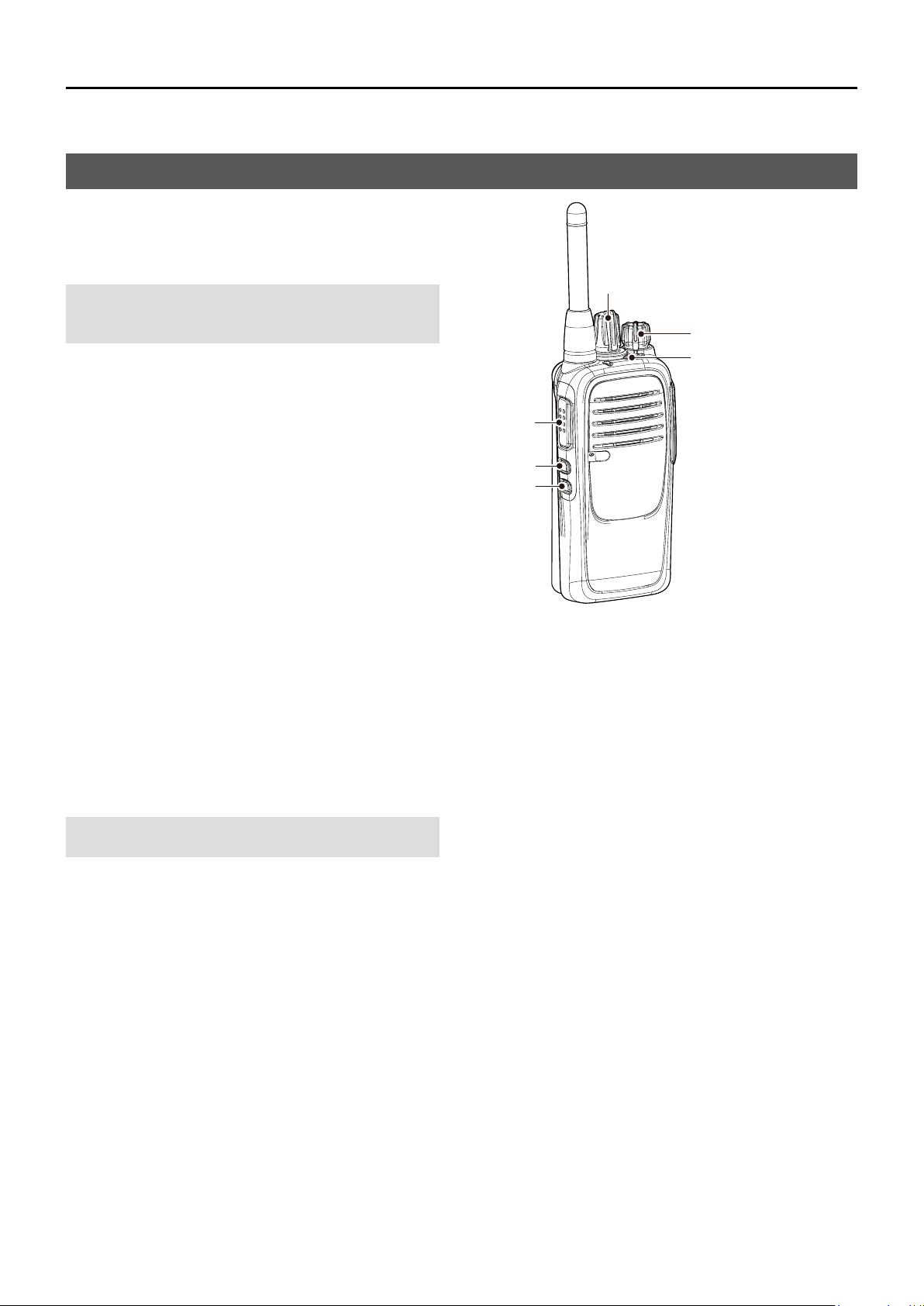
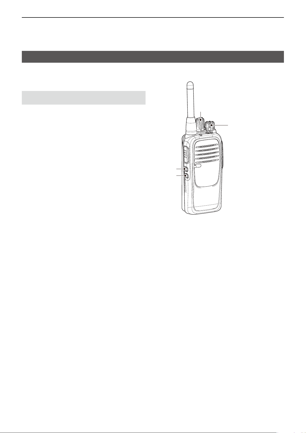
Programmable key functions
You can assign the functions described below to
[Top], [Upper], and [Lower] by using the CS-F29DR2
programming software (purchase separately).
Ask your dealer for details.
NOTE: Refer to the instruction manual that comes
with the transceiver for the default settings of these
keys.
[Rotary Selector]
[VOL]
[Top]
[PTT]
[Upper]
[Lower]
Null
No function is assigned.
ZONE
z Push to select a desired Zone.
z Hold down to announce the current Zone number.
L The Zone number is announced when selecting a
Zone, regardless of the Channel Announce setting.
SCAN
NOTE: Select the channels to be scanned by using
CS-F29DR2 programming software.
z Push to start or pause a scan.
L
When a scan is started with the Power ON Scan or the
Automatic scan function, push this key to pause the
scan. The paused scan resumes after a set time period.
z Hold down this key while a scan is paused, and
then the channel is removed from the scan group.
L The removed channel is automatically added to the
scan group again, after the scan is canceled.
MONI
While holding down this key, the C.Tone* mute is
released, even if the received signal does not include
a matching C.Tone*.
* CTCSS tone or DTCS code
LOCK
Hold down to turn the Key Lock function ON or OFF.
L Even when the Key Lock function is ON, [PTT], [MONI],
[LOCK], [CALL], [CLEAR], [SURVEILLANCE], and
[SIREN] are not locked.
CALL // only on a Digital channel //
Push to make a call that includes a Common ID.
CLEAR // only on a Digital channel //
Pushtonishacommunicationbysendingaclear
down signal. After the other station receives the clear
down signal, the transceiver automatically enters the
Stand-by mode.
BREAK // only on a Digital channel //
z Hold down to send a Break-in request call.
L The Break-in request call announces to the other
stations on the channel that the user wants to break
into the current communication in the group. The
transceiver waits for the current communication to
end. After the communication ends, the transceiver
automatically sends the call.
z While waiting, push this key to cancel the Break-in
request call.
S-RING/C-RING
// only on an Analog channel //
Push to make a Smart-Ring call.
// on both an Analog and a Digital channel //
Hold down to make a Call-Ring call.
3
Page 6

2
Previous view
PROGRAMMABLE KEY FUNCTIONS
Programmable key functions (Continued)
SURVEILLANCE
z Hold down to turn ON the Surveillance function.
z Push to turn OFF the function.
L When the function is ON and a signal is received, a
beep does not sound and the status indicator does not
light, even if you push any key.
SIREN
Hold down to emit a siren sound.
L The siren continues to sound until turning OFF the
transceiver.
L This function is for situations other than an emergency alert,
such as a security alarm.
ANNOUNCE
Push to turn the Channel Announce function ON or
OFF.
L The transceiver announces the position of
[Rotary Selector].
SP. FUNC 1/2
These keys are reserved for future functions. No
function is assigned.
Zone/Announce
z Push to select a desired Zone.
z Hold down to turn the Channel Announce function
ON or OFF.
L The Zone number is announced when selecting a
Zone, regardless of the Channel Announce setting.
4
Page 7
G G G G G G G GGGGGGGGG
G G G G G G G GGGGGGGGG
G G G G G G G GGGGGGGGG
R
G R G R G R G R G R G R G R GRGRGRGRGRGRGRGRG
R
O R O R O R O R O R O R O R ORORORORORORORORO
G G G G G G G GGGGGGGGG
R
G R G R G R G R G R G R G R GRGRGRGRGRGRGRGRG
R
O R O R O R O R O R O R O R ORORORORORORORORO
RR
G G G G G G G GGGGGGGGG
R
G R G R G R G R G R G R G R GRGRGRGRGRGRGRGRG
R
O R O R O R O R O R O R O R ORORORORORORORORO
R
RRR
RR
G G G G G G G GGGGGGGGG
R
G R G R G R G R G R G R G R GRGRGRGRGRGRGRGRG
R
O R O R O R O R O R O R O R ORORORORORORORORO
R
RRR
R
RRRRRRR
G G G G G G G GGGGGGGGG
R
G R G R G R G R G R G R G R GRGRGRGRGRGRGRGRG
R
O R O R O R O R O R O R O R ORORORORORORORORO
R
RRR
R
RRRRRRR
R
R
G G G G G G G GGGGGGGGG
R
G R G R G R G R G R G R G R GRGRGRGRGRGRGRGRG
R
O R O R O R O R O R O R O R ORORORORORORORORO
R
RRR
R
RRRRRRR
R
R
GG
G G G G G G G GGGGGGGGG
R
G R G R G R G R G R G R G R GRGRGRGRGRGRGRGRG
R
O R O R O R O R O R O R O R ORORORORORORORORO
R
RRR
R
RRRRRRR
R
R
G
GGG
G
G
G G G G G G G GGGGGGGGG
R
G R G R G R G R G R G R G R GRGRGRGRGRGRGRGRG
R
O R O R O R O R O R O R O R ORORORORORORORORO
R
RRR
R
RRRRRRR
R
R
G
GGG
G
G
GG
GGGG
G G G G G G G GGGGGGGGG
R
G R G R G R G R G R G R G R GRGRGRGRGRGRGRGRG
R
O R O R O R O R O R O R O R ORORORORORORORORO
R
RRR
R
RRRRRRR
R
R
G
GGG
G
G
GGGGGGGG
G
GGG
G G G G G G G GGGGGGGGG
R
G R G R G R G R G R G R G R GRGRGRGRGRGRGRGRG
R
O R O R O R O R O R O R O R ORORORORORORORORO
R
RRR
R
RRRRRRR
R
R
G
GGG
G
G
G
GGGGGGG
G
GGG
G
GGGRRRROOOO
OO
G G G G G G G GGGGGGGGG
R
G R G R G R G R G R G R G R GRGRGRGRGRGRGRGRG
R
O R O R O R O R O R O R O R ORORORORORORORORO
R
RRR
R
RRRRRRR
R
R
G
GGG
G
G
G
GGGGGGG
G
GGG
G
GGGRRRROOOO
O
OOOOO
OOOOOO
G G G G G G G GGGGGGGGG
R
G R G R G R G R G R G R G R GRGRGRGRGRGRGRGRG
R
O R O R O R O R O R O R O R ORORORORORORORORO
R
RRR
R
RRRRRRR
R
R
G
GGG
G
G
GGGGGGGG
G
GGG
G
GGGRRRROOOO
O
OOOOO
O
OOOOO
O
OOOOO
R
R
G G G G G G G GGGGGGGGG
R
G R G R G R G R G R G R G R GRGRGRGRGRGRGRGRG
R
O R O R O R O R O R O R O R ORORORORORORORORO
R
RRR
R
RRRRRRR
R
R
G
GGG
G
G
GGGGGGGG
G
GGG
G
GGGRRRROOOO
O
OOOOO
O
OOOOO
O
OOOOO
R
R
O
O G
G
G G G G G G G GGGGGGGGG
R
G R G R G R G R G R G R G R GRGRGRGRGRGRGRGRG
R
O R O R O R O R O R O R O R ORORORORORORORORO
R
RRR
R
RRRRRRR
R
R
G
GGG
G
G
GGGGGGGG
G
GGG
G
GGGRRRROOOO
O
OOOOO
O
OOOOO
O
OOOOO
R
R
O
O G
G
O
ORR
Section 3
Previous view
LED INDICATOR
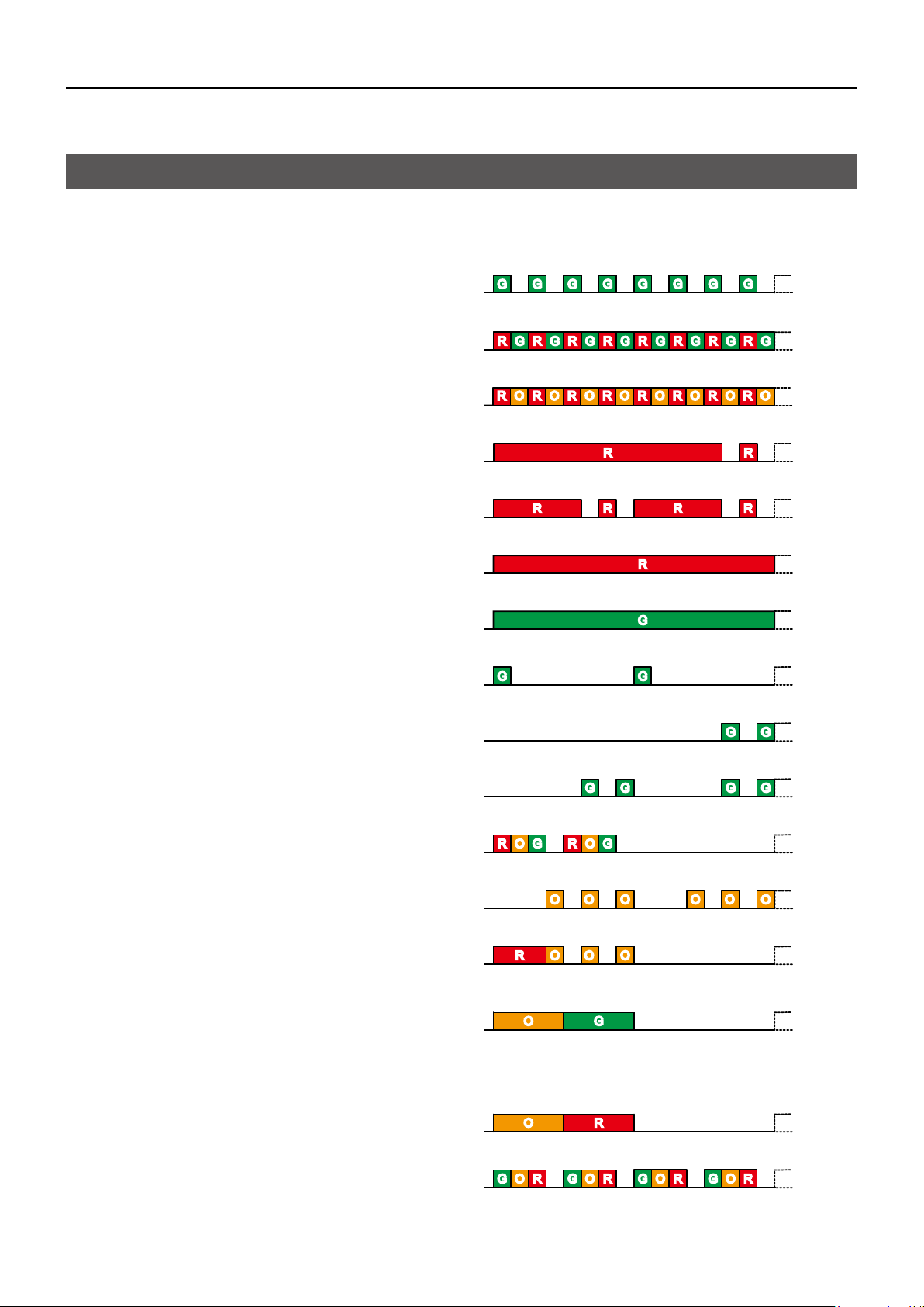
About the LED indicator
The LED indicator indicates the status of various
parameters of the transceiver as follows:
(Reference: R is Red, G is Green, O is Orange)
z Programming (reading or writing data)
z Programming error (if writing fails)
z Inh, Blank CH, Unlocked (when you cannot use the
channel)
z TX low Battery 1 (while transmitting)
z TX Low Battery 2 (while transmitting)
z Transmitting
z Receiving
z Scanning
z Low Battery 1 (You should charge the battery.)
z Low Battery 2 (You must charge the battery.)
R G R G R G R G R G R G R G R GRGRGRGRGRGRGRGRG
R
R
RR
GG
GGGG
GGG
R
RRRRR
GGGG
GGG
z When turning ON the power
z Making a Smart-Ring call
z Lockout, TX Inh, TOT (when transmit is inhibited)
z Success:
• On an analog channel, blinks when a Smart-Ring
call is successful.
• On a digital channel, blinks when sending a
Break-in request call.
z Smart-Ring call failed
z Siren
GGGGRRRROOOO
OOOOOO
OOOOOO
RR
OO G
OORR
RRRRRRR
O
G
GGGGGGG R
OOO
OOOOOOOO G
5
Page 8

Section 4
Previous view
SETTINGS
Setting the Beep function
You can turn the Beep function ON or OFF.
NOTE: Turn ON the Beep function when you set the
beep and announcement level, Call-Ring ringer, ringer
level, microphone gain, squelch level, VOX function,
or VOX gain to check the current level setting by
counting or hearing beeps. (pp. 8 ~ 14)
[Rotary Selector]
1. Rotate [VOL] to turn OFF the transceiver.
2. Set [Rotary Selector] to any channel other than
Channel 16.
3. While holding down [Lower], rotate [VOL] to
turn ON the transceiver to enter the Beep Level
Adjustment mode.
• An opening beep sounds and the selected channel
number will be announced.
4. Push [Lower] to turn the Beep function ON or
OF F.
• When a beep sounds after pushing [Lower], the Beep
function is ON.
• When no beep sounds after pushing [Lower], the Beep
function is OFF.
L The transceiver stores the setting every time you
change it.
L If desired, push [Upper] to adjust the beep level. See
page 8 for details.
5. Rotate [VOL] to turn OFF the transceiver and exit
the Beep Level Adjustment mode.
[VOL]
[Upper]
[Lower]
7
Page 9
4
Pushing
[Upper]
Previous view
SETTINGS
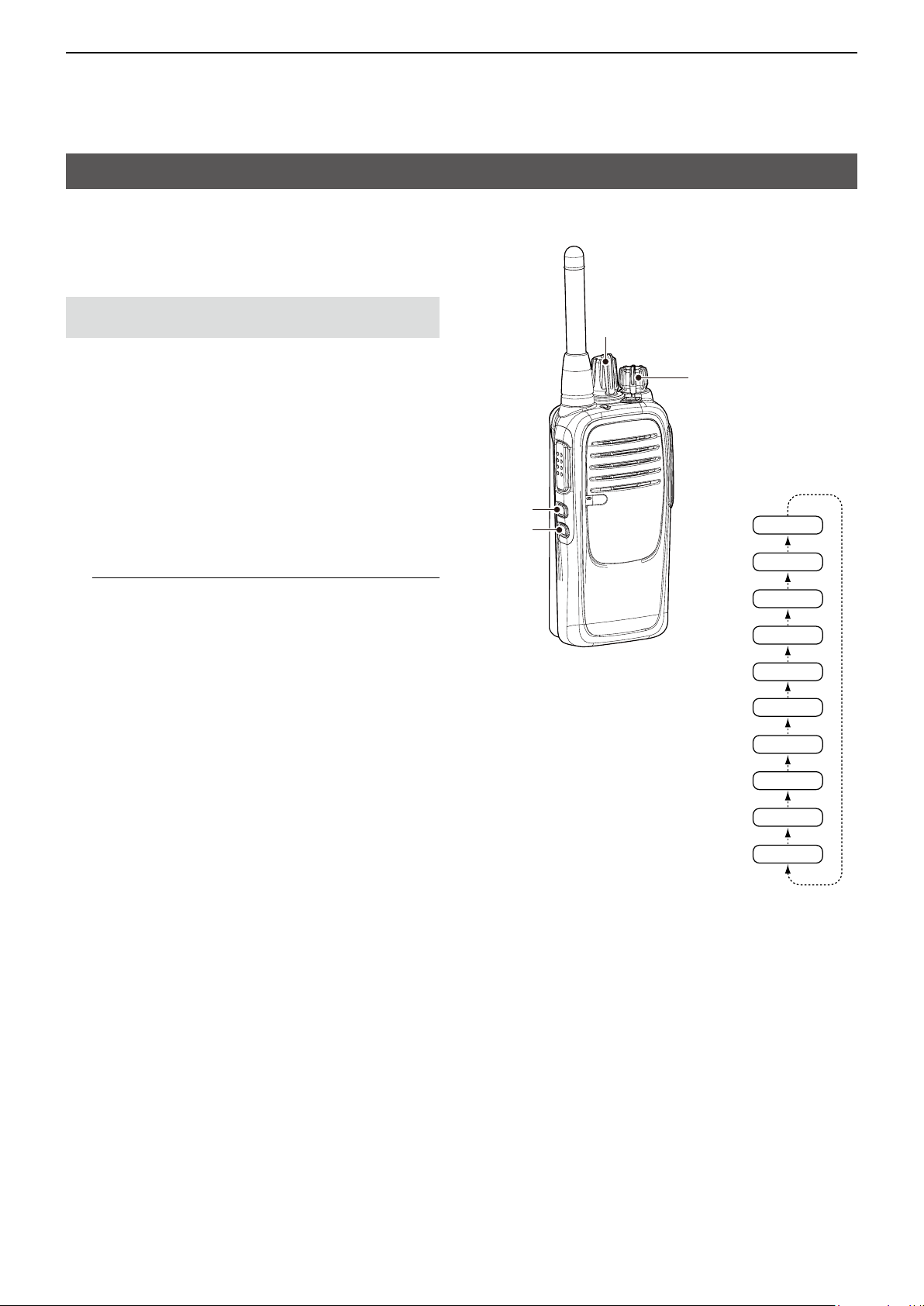
Setting the beep and announcement level
You can adjust the beep and announcement level
between 1 and 5, or 1 (linked) and 5 (linked). When
a linked option is selected, the beep audio level is
adjustable by rotating [VOL].
NOTE:Turn ON the Beep function (p. 7) before
you start setting the beep and announcement level.
1. Rotate [VOL] to turn OFF the transceiver.
2. Set [Rotary Selector] to any channel other than
Channel 16.
3. While holding down [Lower], rotate [VOL] to turn
ON the transceiver and enter the Beep Level
Adjustment mode.
• An opening beep sounds and the selected channel
number will be announced.
4. Push [Upper] to change the beep level.
• A beep sounds every time you push [Upper].
Therefore, you can determine the current level setting
by the increasing loudness of the beep that sounds.
InformationL
• The adjustable range is 1 to 5 or 1 (Linked) to 5
(Linked).
• Repeatedly pushing [Upper] rst selects 1 (lowest) to
5 (highest), and then selects the lowest linked level,
1 (Linked) to the highest, 5 (Linked). Repeatedly
pushing [Upper] repeats the cycle. See the illustration
to the right.
• To determine if you have selected a linked level, set
[VOL] to minimum, then push [Upper] repeatedly,
listening for the loudest beep (level 5). Pushing
[Upper] once after the loudest beep will select 1
(Linked). Repeatedly push [Upper] to select the
desired linked level.
5. Rotate [VOL] to turn OFF the transceiver and exit
the Beep Level Adjustment mode.
[Upper]
[Lower]
[Rotary Selector]
[VOL]
5
4
3
2
1
5 (Linked)
4 (Linked)
3 (Linked)
2 (Linked)
1 (Linked)
8
Page 10

4
Previous view
SETTINGS
Setting the Call-Ring ringer
The Call-Ring ringer sounds only when the user holds
down [S-Ring/C-Ring] to make a call.
NOTE: Turn ON the Beep function (p. 7) before
you start setting the Call-Ring ringer.
1. Rotate [VOL] to turn OFF the transceiver.
2. Set [Rotary Selector] to any channel other than
Channel 16.
3. While holding down [PTT] and [Lower], rotate
[VOL] to turn ON the transceiver and enter the
Call-Ring ringer setting mode.
• The current Call-Ring ringer sounds.
4. Rotate [Rotary Selector] to select a desired Call-
Ring ringer.
• The selected Call-Ring ringer sounds.
5. Rotate [VOL] to turn OFF the transceiver and exit
the Call-Ring ringer setting mode.
[Rotary Selector]
[VOL]
[PTT]
[Lower]
9
Page 11

4
Pushing
[Lower]
Pushing
[Upper]
Previous view
SETTINGS
Setting the ringer level
You can adjust the ringer level between 1 and 5,
or 1 (Linked) and 5 (Linked). When a linked option
is selected, the ringer audio level is adjustable by
rotating [VOL].
NOTE: Turn ON the Beep function (p. 7) before
you start setting the ringer level.
[Rotary Selector]
1. Rotate [VOL] to turn OFF the transceiver.
2. Set [Rotary Selector] to Channel 16.
3. While holding down [Lower], rotate [VOL] to turn
ON the transceiver and enter the Ringer Level
Adjustment mode.
• An opening beep sounds and
announced.
“Sixteen”
will be
4. Push [Upper] to increase, or push [Lower] to
decrease the ringer level.
• A beep sounds after pushing [Upper] or [Lower].
Therefore, you can determine the current level setting
by the increasing or decreasing loudness of the beep
that sounds.
InformationL
• The adjustable range is 1 to 5 or 1 (Linked) to 5
(Linked).
• Repeatedly pushing [Upper] rst selects 1 (lowest) to
5 (highest), and then selects the lowest linked level,
1 (Linked) to the highest, 5 (Linked). Repeatedly
pushing [Upper] or [Lower] repeats the cycle. See the
illustration to the right.
• To determine if you have selected a linked level,
set [VOL] to minimum, then push [Upper] up to 10
times, listening for the loudest beep (level 5). Pushing
[Upper] once after the loudest beep will select 1
(Linked). Repeatedly push [Upper] or [Lower] to select
the desired linked level.
5. Rotate [VOL] to turn OFF the transceiver and exit
the Ringer Level Adjustment mode.
[VOL]
[Upper]
[Lower]
5
4
3
2
1
5 (Linked)
4 (Linked)
3 (Linked)
2 (Linked)
1 (Linked)
10
Page 12
4
Previous view
SETTINGS
Setting the microphone gain
You can adjust the microphone gain. Higher values
make the microphone more sensitive to the user
voice.
NOTE: Turn ON the Beep function (p. 7) before
you start setting the microphone gain.
1. Rotate [VOL] to turn OFF the transceiver.
2. Set [Rotary Selector] to Channel 16.
3. While holding down [Upper], rotate [VOL] to turn
ON the transceiver and enter the Microphone
Gain Adjustment mode.
• An opening beep sounds and “Sixteen” is announced.
4. Push [Upper] to increase, or push [Lower] to
decrease the microphone gain.
• A beep sounds after pushing [Upper] or [Lower].
An error beep sounds if you try to exceed the
adjustable range.
L The adjustable range is 1 (minimum) to 4
(maximum).
5. Rotate [VOL] to turn OFF the transceiver and exit
the Microphone Gain Adjustment mode.
[Rotary Selector]
[VOL]
[Upper]
[Lower]
11
Page 13

4
Previous view
SETTINGS
Setting the squelch level
You can adjust the squelch level. The squelch circuit
mutes the received audio or noise signal, depending
on signal strength.
NOTE: Turn ON the Beep function (p. 7) before
you start setting the squelch level.
1. Rotate [VOL] to turn OFF the transceiver.
2. Set [Rotary Selector] to any channel other than
Channel 16.
3. While holding down [Upper], rotate [VOL] to turn
ON the transceiver and enter the Squelch Level
Adjustment mode.
• An opening beep sounds and the selected channel
number will be announced.
4. Push [Upper] to increase the squelch level (tight
squelch), or push [Lower] to decrease the squelch
level (loose squelch).
• A beep sounds after pushing [Upper] or [Lower].
An error beep sounds if you try to exceed the
adjustable range.
L The adjustable range is 0 (loose squelch) to 9 (tight
squelch).
5. Rotate [VOL] to turn OFF the transceiver and exit
the Squelch Level Adjustment mode.
[Rotary Selector]
[VOL]
[Upper]
[Lower]
12
Page 14

4
Previous view
SETTINGS
Setting the VOX function
You can turn the VOX function ON or OFF. The VOX
function automatically switches between receive and
transmit using your voice.
NOTE: Turn ON the Beep function (p. 7) before
you start setting the VOX function.
1. Rotate [VOL] to turn OFF the transceiver.
2. Set [Rotary Selector] to any channel other than
Channel 16.
3. While holding down [PTT] and [Upper], rotate
[VOL] to turn ON the transceiver, to turn the VOX
function ON or OFF.
• When the VOX function is ON, an opening beep and a
beep sounds, and then the selected channel number
is announced.
• When the VOX function is OFF, an opening beep
and two beeps sound, and then the selected channel
number is announced.
4. Rotate [VOL] to turn OFF the transceiver, then
turn ON again to restart normal operation.
[Rotary Selector]
[VOL]
[PTT]
[Upper]
13
Page 15
4
Previous view
SETTINGS
Setting the VOX gain
You can adjust the VOX gain. Higher values make the
VOX function more sensitive to the user voice.
NOTE: Turn ON the Beep function (p. 7) before
you start setting the VOX gain.
1. Rotate [VOL] to turn OFF the transceiver.
2. Set [Rotary Selector] to Channel 16.
3. While holding down [PTT] and [Upper], rotate
[VOL] to turn ON the transceiver and enter the
VOX Gain Adjustment mode.
• An opening beep sounds and
“Sixteen”
is announced.
4. Push [Upper] to increase, or push [Lower] to
decrease the VOX gain.
• A beep sounds after pushing [Upper] or [Lower].
An error beep sounds if you try to exceed the
adjustable range.
L The adjustable range is 1 (minimum) to 10
(maximum).
5. Rotate [VOL] to turn OFF the transceiver and exit
the VOX Gain Adjustment mode.
[Rotary Selector]
[VOL]
[PTT]
[Upper]
[Lower]
14
Page 16

Section 5
Previous view
Section 5
dPMR™ OPERATION
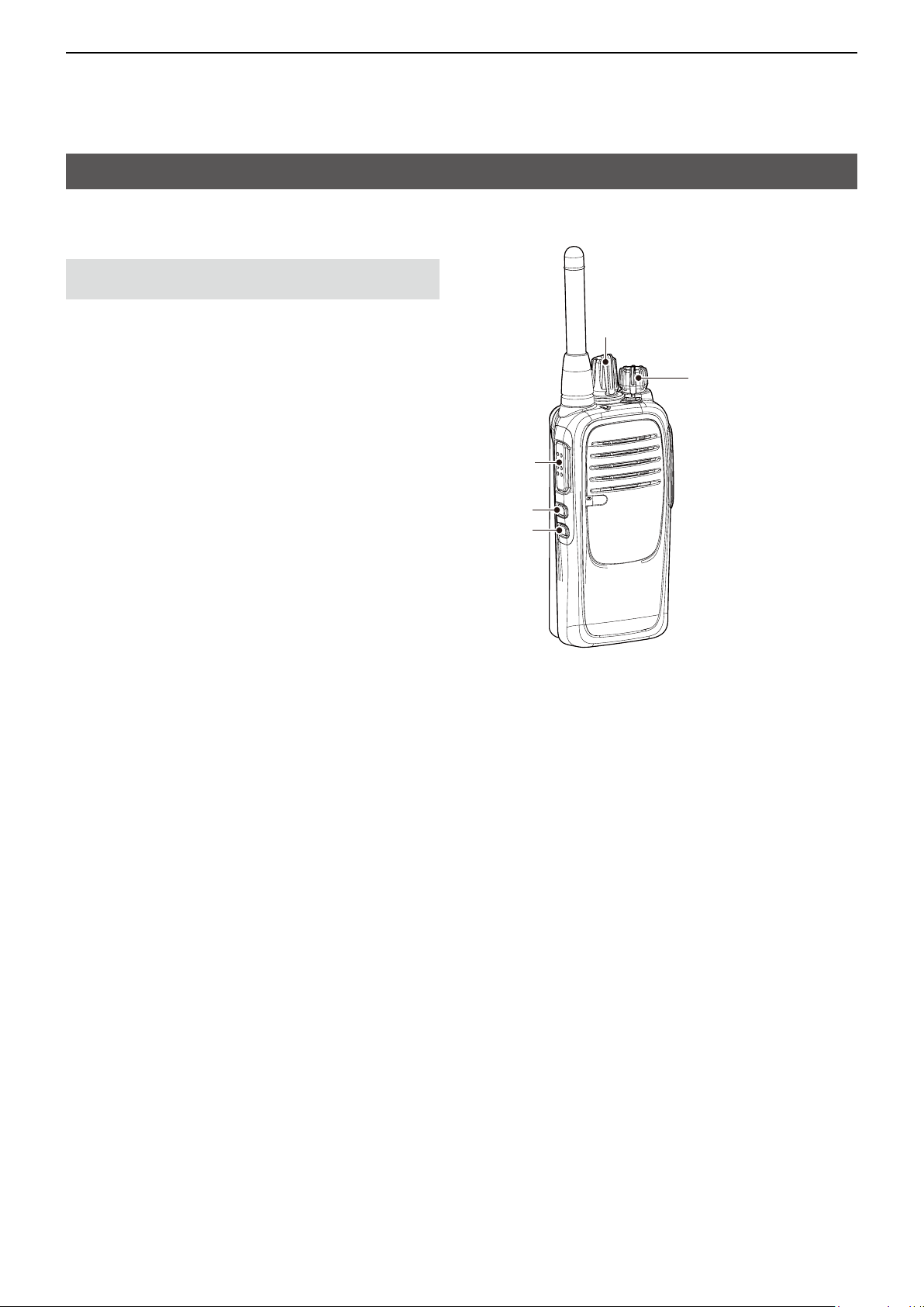
Receiving and transmitting
D Receiving
1. Rotate [Rotary Selector] to select a channel.
2. When receiving a call, rotate [VOL] to adjust the
audio.
NOTE: When a call is received:
• Beeps sound, and the mute is released.
• The LED indicator lights green.
[Rotary Selector]
[VOL]
LED indicator
15
Page 17

5
Previous view
dPMR™ OPERATION
Receiving and transmitting
D Transmitting
You can make a call to a station that has the same
Common ID. Other digital mode transceivers on the
channel will not receive the call that does not match
their Common ID.
Before making a call, wait until the channel is clear to
avoid interference.
Using [PTT]:
1. Rotate [Rotary Selector] to select a channel.
2. Push [PTT] to call a station.
3. Hold down [PTT] and speak at your normal voice
level.
4. Release [PTT] to receive.
5. Push [Clear]* to send a ‘Disconnect’ signal to
terminate the call.
Using the [S-Ring/C-Ring]:
1. Rotate [Rotary Selector] to select a channel.
2. Hold down [S-Ring/C-Ring] for 1 second to call a
station.
3. Hold down [PTT] and speak at your normal voice
level.
4. Release [PTT] to receive.
5. Push [Clear]* to send a ‘Disconnect’ signal to
terminate the call.
[Rotary Selector]
[PTT]
Using the [Call]*:
1. Rotate [Rotary Selector] to select a channel.
2. Push [Call]* to send a call request.
NOTE: After receiving a call request, a ringer sounds
on a receive transceiver.
3. Hold down [PTT] and speak at your normal voice
level.
4. Release [PTT] to receive.
5. Push [Clear]* to send a ‘Disconnect’ signal to
terminate the call.
* Assign the function to a programmable key by using
the CS-F29DR2 programming software (purchase
separately). Ask your dealer for details.
NOTE: To insure the readability of your signal:
1. After pushing [PTT], pause briefly before you
start speaking.
2.
Hold the microphone 5 to 10 cm from your mouth,
and then speak at your normal voice level.
16
Page 18
5
Station
Previous view
dPMR™ OPERATION
Break-in function
You can send a Break-in request call.
The Break-in request call announces to the other
stations on the channel that the user wants to break
into the current communication in the group.
The transceiver waits for the current communication to
end, and then sends the call.
D Receiving
1. When receiving a Break-in request call, the ringer
sounds, and the LED indicator blinks orange.
2. Push any key to stop the ringer sounding and the
LED blinking.
D Transmitting
While receiving an audio signal, hold down [Break]*
for 1 second to send a Break-in request call.
NOTE:
• The transceiver waits for the communication to end,
and then sends the call.
• To cancel the Break-in request call, push [Break]*
while waiting.
* Assign the function to a programmable key by using
the CS-F29DR2 programming software (purchase
separately).
Ask your dealer for details.
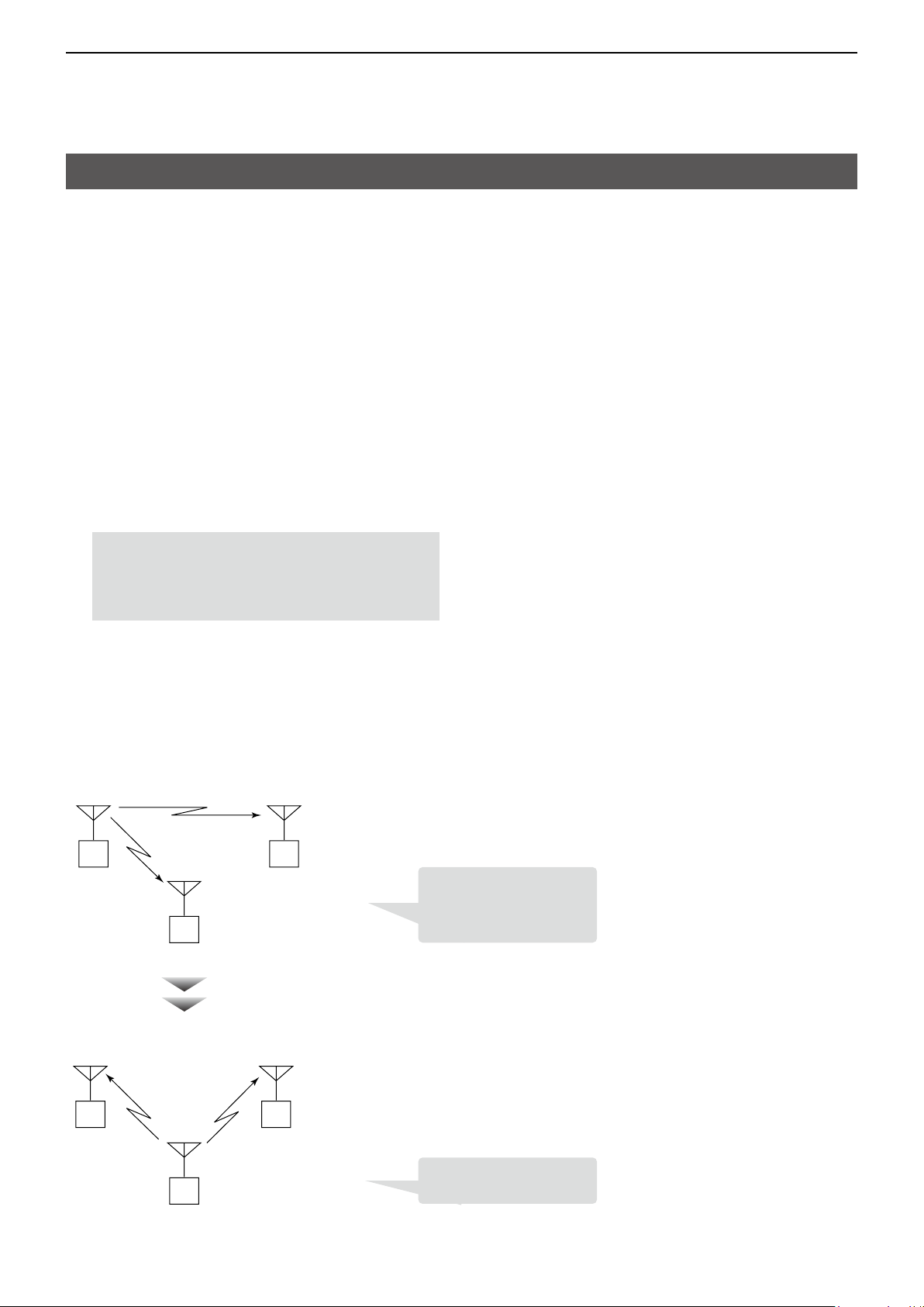
Example: Station A, B, and C are communicating
using the same Common ID.
Station A Station B
Push
[Break]
Station C
Wait
Station C pushes [Break] to
transmit the break-in request
call while Station A is
transmitting.
After Station A releases [PTT] (transmission is finished.)
Break! Break!
A Station B
Station C
Station A and B receive the
break-in request signal.
17
Page 19

5
Previous view
dPMR™ OPERATION
Status call
D Receiving
When receiving a Status message, the ringer sounds
and the LED indicator status changes, according to
the presetting.
Ask your dealer for details.
NOTE: You cannot send a Status call with the
IC-F29DR2.
LED indicator
18
Page 20

Section 6
Previous view
OTHER FUNCTIONS
Setting a scan type
You can set to whether the transceiver scans all
channels across the zone (All), or scans channels in a
selected zone (Zone).
NOTE: Turn ON the Beep function (p. 7) before
you start setting a scan type.
1. Rotate [VOL] to turn OFF the transceiver.
2. Set [Rotary Selector] to Channel 16.
3. While holding down [PTT], rotate [VOL] to turn ON
the transceiver to set a scan type and confirm the
number of beeps.
z Ifyouwanttosetto“All,”conrmabeepandan
opening beep sound when you do step 3.
If 2 beeps and an opening beeps sound, turn off
the transceiver, then do step 3 again.
z Ifyouwanttosetto“Zone,”conrm2beeps
and an opening beep sound when you do step
3.
If a beep and an opening beep sound, turn off
the transceiver, then do step 3 again.
4. Rotate [VOL] to turn OFF the transceiver, then
turn ON again to save the setting.
To start a scan, push the key assigned the scan
function.
[Rotary Selector]
[VOL]
[PTT]
19
Page 21

6
Previous view
OTHER FUNCTIONS
Tone Scan function
This function is effective when the user wants to
communicate with another station but does not know
its CTCSS tone or DTCS code setting.*
* Depending on the presetting.
Ask your dealer for details.
NOTE: Turn ON the Beep function (p. 7) before
you enter the Tone Scan mode.
1. Rotate [VOL] to turn OFF the transceiver.
2. Set [Rotary Selector] to any channel other than
Channel 16.
3. While holding down [Upper] and [Lower], rotate
[VOL] to turn ON the transceiver and enter the
Tone Scan mode.
• An opening beep sounds and the current channel
number is announced. (Example: Ten)
4. Rotate [Rotary Selector] to select a desired
channel that you want to assign the detected
CTCSS tone or DTCS code to.
• The selected channel number will be announced.
5. Hold down [Upper] for 1 second to start a scan.
• The LED indicator blinks green slowly.
6. When detecting a matching tone or code, the scan
pauses, and the tone or code is automatically set
to the channel.
7. Push [Upper] to cancel the scan.
NOTE: The scan resumes 3 seconds (default) after
the signal disappears.
8. Rotate [VOL] to turn OFF the transceiver and exit
the Tone Scan mode.
[Rotary Selector]
[VOL]
[Upper]
[Lower]
20
Page 22

A7437-3EU
© 2018 Icom Inc.
1-1-32 Kamiminami, Hirano-ku, Osaka 547-0003, Japan
 Loading...