

Page 1
INSTRUCTION MANUAL
VHF TRANSCEIVER
iF1610
UHF TRANSCEIVER
iF2610
Page 2

IMPORTANT
CAUTIONS
READ ALL INSTRUCTIONS carefully and com-
pletely before using the transceiver.
RWARNING! NEVER connect the transceiver to an
AC outlet. This may pose a fire hazard or result in an electric
shock.
SAVE THIS INSTRUCTION MANUAL—This in-
struction manual contains important operating instructions for
the IC-F1610 VHF TRANSCEIVER or IC-F2610 UHF
TRANSCEIVER.
NEVER connect the transceiver to a power source of more
than 16 V DC such as a 24 V battery. This connection will ruin
the transceiver.
NEVER cut the DC power cable between the DC plug and
EXPLICIT DEFINITIONS
fuse holder. If an incorrect connection is made after cutting,
the transceiver might be damaged.
NEVER place the transceiver where normal operation of
WORD DEFINITION
RWARNING
CAUTION
NOTE
Personal injury, fire hazard or electric
shock may occur.
Equipment damage may occur.
If disregarded, inconvenience only. No risk
of personal injury, fire or electric shock.
the vehicle may be hindered or where it could cause bodily
injury.
Place unit in a secure place to avoid inadvertent use by children.
NEVER expose the transceiver to rain, snow or any liquids.
USE supplied microphones only. Other microphones have
different pin assignments and may damage the transceiver.
Versions of the transceiver which display the “CE” on the se-
rial number seal, comply with the essential requirements of
the 89/336/EEC directive for Electromagnetic Compatibility.
ii
SmarTrunk II™ is a trademark of SmarTrunk Systems, Inc.
Page 3

DO NOT connect the transceiver to a power source using
reverse polarity. This connection will not only blow fuses but
also may damage the transceiver.
DO NOT use or place the transceiver in areas with tem-
peratures below –20°C or above +55°C or, in areas subject
to direct sunlight, such as the dashboard.
AVOID operating the transceiver without running the vehi-
cle’s engine. The vehicle’s battery will quickly run out if the
transceiver is in transmission while the vehicle’s engine is off.
AVOID placing the transceiver is excessively dusty envi-
ronments.
AVOID placing the transceiver against walls. This will ob-
struct heat dissipation.
AVOID the use of chemical agents such as benzine or al-
cohol when cleaning, as they can damage the transceiver’s
surfaces.
BE CAREFUL! The transceiver will become hot when
operating continuously for long periods.
iii
Page 4
qw
r
t
y
u
i
o!0 !1
!2
!3
e
LCD-STICKER
TABLE OF CONTENTS
IMPORTANT . . . . . . . . . . . . . . . . . . . . . . . . . . . . . . . . . . . . ii
EXPLICIT DEFINITIONS . . . . . . . . . . . . . . . . . . . . . . . . . . . ii
CAUTIONS . . . . . . . . . . . . . . . . . . . . . . . . . . . . . . . . . . . . . ii
TABLE OF CONTENTS . . . . . . . . . . . . . . . . . . . . . . . . . . . iv
SUPPLIED ACCESSORIES . . . . . . . . . . . . . . . . . . . . . . . . iv
1 PANEL DESCRIPTION . . . . . . . . . . . . . . . . . . . . . . . . 1–6
■ Front panel . . . . . . . . . . . . . . . . . . . . . . . . . . . . . . . . . . 1
■ Programmable function keys . . . . . . . . . . . . . . . . . . . . 2
■ Function display . . . . . . . . . . . . . . . . . . . . . . . . . . . . . . 6
2 OPERATION . . . . . . . . . . . . . . . . . . . . . . . . . . . . . . . . 7–9
■ Turning power on . . . . . . . . . . . . . . . . . . . . . . . . . . . . . 7
■ Channel selection . . . . . . . . . . . . . . . . . . . . . . . . . . . . . 7
■ Receiving and transmitting . . . . . . . . . . . . . . . . . . . . . . 8
3 CONNECTION AND INSTALLATION . . . . . . . . . . . 10–13
iv
■ Rear panel connections . . . . . . . . . . . . . . . . . . . . . . . 10
■ Mounting . . . . . . . . . . . . . . . . . . . . . . . . . . . . . . . . . . 12
■ Seaparation . . . . . . . . . . . . . . . . . . . . . . . . . . . . . . . . 12
■ Optional UT-105 installation . . . . . . . . . . . . . . . . . . . . 13
4 OPTIONAL SmarTrunk II™ OPERATION . . . . . . . 14–16
■ SmarTrunk II™ and conventional modes . . . . . . . . . . 14
■ SmarTrunk II™ operation . . . . . . . . . . . . . . . . . . . . . . 14
5 OPTIONS . . . . . . . . . . . . . . . . . . . . . . . . . . . . . . . . . . . . 17
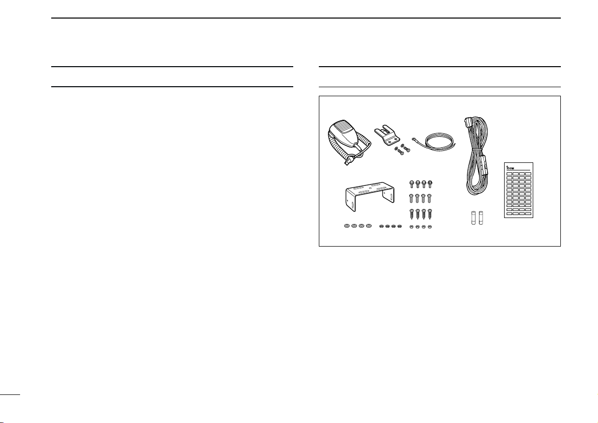
SUPPLIED ACCESSORIES
q Microphone (HM-100) . . . . 1
w Microphone hanger and
screw set . . . . . . . . . . . 1 set
e Microphone cable . . . . . . . 1
r DC power cable
(OPC-345) . . . . . . . . . . . . . 1
t Mounting bracket . . . . . . . . 1
y Bracket bolts . . . . . . . . . . . 4
NOTE: Some versions include the SP-22
D Function name stickers
Use these to label the programmable function keys ([P0] to
[P4]) according to their assigned functions.
u Mounting screws (M5 × 12) 4
i Self-tapping screws
(M5 × 20) . . . . . . . . . . . . . . 4
o Flat washers . . . . . . . . . . . 4
!0 Spring washers . . . . . . . . . 4
!1 Nuts . . . . . . . . . . . . . . . . . . 4
!2 Fuses (15A) . . . . . . . . . . . . 2
!3 Function name stickers 1 set
EXTERNAL SPEAKER
.
Page 5
PANEL DESCRIPTION
1
P
4P3P2P1P0
23
456
789
M
0#
LOW
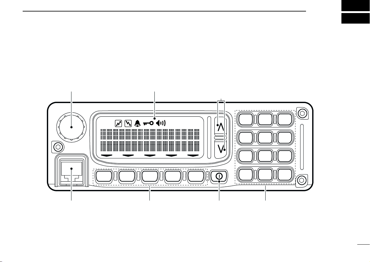
VOLUME CONTROL FUNCTION DISPLAY (p. 6) CH UP/DOWN KEYS (p. 2)
(programmable)
MICROPHONE
CONNECTOR
POWER
SWITCH
PROGRAMMABLE
FUNCTION KEYS
(pgs. 2–6)
KEYPAD
■ Front panel
1
1
Page 6

1
PANEL DESCRIPTION
VOLUME CONTROL
Adjusts the audio output
• Minimum audio level (when setting control maximum counter clock-
wise) is pre-programmed.
CHANNEL UP/DOWN KEYS [ ]/[ ]([CH UP]/[CH DN])
Push to select an operating channel.
• Can be programmed for one of several functions by your dealer.
POWER SWITCH
Turns the power on and off.
• The following functions are available at power on as options:
➥ Automatic scan start
➥ Password prompt
KEYPAD
The keypad allows you to enter digits to:
➥ Select memory channels
➥ Select tone channels
➥ Select DTMF codes (during transmit)
➥ Set SmarTrunk II™ codes
MICROPHONE CONNECTOR
Connects the supplied microphone or optional DTMF microphone for SmarTrunk II™ operation.
NEVER connect other microphones. The pin assignments
may be different and the transceiver may be damaged.
MICROPHONE
The supplied microphone has a PTT switch and a cradle. The
following functions are available when the microphone is
taken off the cradle or put back on hook:
➥ Automatic scan start when putting on hook
➥ Automatic priority channel selection when taken off hook
➥ Set to ‘inaudible’ (mute condition) when putting on hook
➥ Set to ‘audible’ (unmute condition) when taken off hook
■ Programmable keys
The following functions can be assigned to the programmable
function keys. Assigned function names can be affixed to the
corresponding keys using the supplied stickers*.
*Some functions do not have supplied stickers.
D Programmable functions with supplied
stickers
MEMORY CHANNEL KEYS
MR–1
MR–2
MR–3
MR–4
Select a memory channel directly.
2
Page 7

PANEL DESCRIPTION
1
BANK KEY
BANK
Selects a memory bank.
PRIORITY CHANNEL KEYS
PRI A
Select priority A or priority B channel.
PRI B
SCAN KEYS
SCN A
Start/stop scan A or scan B.
SCN B
SCAN TAG KEY
TAG
•“ ” appears above the [TAG] key when the channel belongs to
the scan group.
Adds or deletes the selected channel to the scan
group.
MONITOR KEY
MONI
• Push and hold the key to unmute the channel (audio is emitted; ‘au-
dible’ condition).
• Push the key to toggle the mute and unmute conditions (toggles ‘au-
dible’ and ‘inaudible’).
• Push the key to mute the channel (sets to ‘inaudible’ only).
Activates one of (or two of) the following functions
on each channel independently.
• Push the key to unmute the channel (sets to ‘audible’ only).
• Push the key after communication is finished to send a ‘reset code.’
☞ NOTE: The unmute condition (‘audible’ conditions) may
automatically return to the mute condition (‘inaudible’ condition) after a specified period.
PUBLIC ADDRESS KEY
When an optional OPC-617
PA
the audio output via the cable can be controlled
from the transceiver separately from the [VOLUME] control.
• This audio output can be used as a ‘public address’ function when
an external audio amplifier and speaker are connected additionally.
• Push this key, then speak into the microphone while pushing the
PTT switch.
• The [CH UP]/[CH DN] keys allow you to set the audio output level
from minimum to maximum.
EXTERNAL SPEAKER KEY
When external connections are made for the ‘public
SP
address’ function, the external speaker drive function is also available simultaneously. The received audio can
be heard via the external speaker when this key is pushed.
• This function is useful when you are out of the vehicle.
• The audio output level is linked to the transceiver’s volume control.
LOCK KEY
LOCK
Electronically locks all programmable keys except
ACC CABLE
is installed,
3
Page 8

1
PANEL DESCRIPTION
the following:
[CALL] (incl. CAL A and CAL B), [MONI] and [EMER] keys.
OUTPUT POWER SELECTION KEYS
LOW1
LOW2
Select the transmit output power temporarily or permanently, depending on the pre-setting.
• Ask your dealer or system operator for the output power
level for each selection.
BEEP KEY
BEEP
Push to toggle beep tones on and off.
• These are the confirmation beep tones that by default are
emitted each time a key is pushed.
LIGHT KEY
LITE
Push to select the keypad and LCD backlighting
condition.
ON : Turns backlighting on continously.
OFF : Turns backlighting off.
AUTO : Turns backlighting on or off depending on the ACC
socket pin 1 voltage.
ON: low (0 V) OFF: high (12 V)
CONTINUOUS TONE CHANNEL ENTRY KEY
TONE
Push this key, then input a continous tone memory
channel number via the keypad to change the tone
frequency.
TALK AROUND KEY
Toggles the talk around function on and off.
TA
• The talk around function equalizes the transmit frequency
to the receive frequency for mobile-to-mobile communi-
cation.
WIDE/NARROW KEY
W/N
• This function is available for wide/narrow transceiver versions only.
Push [W/N] to toggle the bandwidth between wide
and narrow operation.
DTMF CHANNEL SELECT KEY
DTMF
➥ Push this key to select a DTMF channel.
• Push this key, then select the desired DTMF channel
using the [CH UP]/[CH DN] keys.
➥ Push and hold this key to transmit the selected DTMF
code.
CALL KEYS
CALL
CAL A
CAL B
Transmit a 5-tone call.
• Call transmission is necessary before you call another
station, depending on your signalling system.
• The [CAL A] and/or [CAL B] keys may be available when
your system employs selective ‘Individual/Group’ calls.
Ask your system operator which call is assigned to each
key.
4
Page 9

PANEL DESCRIPTION
1
EMERGENCY KEY
EMER
• If you want to cancel the emergency call, push (or push and hold)
the key again before transmitting the call.
• The emergency call is transmitted one time only or repeatedly until
receiving a control code, depending on the pre-settting.
TX CODE KEY
CODE
• Push and hold to change the contents of the station code using the
[CH UP]/[CH DN] keys.
• Push to select a TX 5-tone code channel using the [CH UP]/[CH
DN] keys after pushing this key.
ID MEMORY READ KEY
ID MR
➥ Push and hold this key to erase all memorized ID’s.
OPT
TRUNKING GROUP KEY
GRP
Push and hold the key to transmit an emergency
call.
Selects a transmit 5-tone code (station code) channel.
➥ Recalls detected ID codes.
• Push this key, then push [CH UP]/[CH DN] for selec-
tion.
• Up to 5 ID’s are remembered.
OPTION KEY
Push to select a trunking group (when operating in
SmarTrunk II™ mode).
D Programmable functions without supplied
stickers
TX CODE CHANNEL UP/DOWN KEY
Push to select a TX code channel directly.
CHANNEL UP/DOWN FUNCTION
When a key is assigned this function, push it to increment or
decrement the operating channel.
CHANNEL SELECT FUNCTION
When a key is assigned this function, push it to increment or
decrement the operating channel.
BANK UP/DOWN FUNCTION
When a key is assigned this function, push it to increment or
decrement the selected channel bank.
PRIORITY CHANNEL A REWRITE FUNCTION
When a key is assigned this function:
➥ Push momentarily to select PRIO A channel.
➥ Push and hold to set the current channel to PRIO A.
DTMF RE-DIAL FUNCTION
When a key is assigned this function, push it to automatically
re-dial the most recent (manually transmitted) DTMF code.
5
Page 10

1
LOW
qwe r t y
ui
CH09 173.9 W LOW
PANEL DESCRIPTION
TX CODE CHANNEL UP/DOWN FUNCTION
When a key is assigned this function, push it to increment or
decrement the TX code channel.
TURBO SpeeDial A/B/C/D FUNCTIONS
During SmarTrunk II™ operation, when a key is assigned this
function, push it to automatically dial a commonly used number with one push.
■ Function display
q TRANSMIT INDICATOR
Appears while transmitting or sending a 5-tone code.
w BUSY INDICATOR
Appears while the channel is busy.
e BELL INDICATOR
Appears or flashes when the specified 5-tone call is received.
r LOCK INDICATOR
6
Appears when the lock function is activated.
t AUDIBLE INDICATOR
Appears when the channel is in the ‘audible’ condition
(unmute) condition.
y LOW POWER INDICATOR
Appears when the selected channel is set for low power
output.
u ACTIVATED KEY INDICATOR
Appears or flashes to indicate the key directly below it
has been activated.
i DOT MATRIX INDICATORS
These 2 lines of 16 characters each display operating information such as the selected channel, frequency, etc.
Page 11

OPERATION
2
■ Turning power on
➀ Push [ ] to turn power on.
• A power-up alert tone sounds for about 1 sec. and an opening
message may appear.
➁ If the transceiver is programmed with a startup password,
input the code from the keypad as instructed by your system operator.
➂ When the password prompt does not clear after inputting
the code, you may have input the code incorrectly. In such
a case, turn power off, then on again.
■ Channel selection
The method for selecting channels may differ according to
your system.
NON-BANK TYPE:
Push the
ing channel, in sequence or;
push one of the digit keys on the keypad to select a channel
directly.
BANK TYPE:
➀ Push [BK S], then push [CH UP]/[CH DN] to select the de-
➁ Push [CH UP]/[CH DN] to select the desired channel in the
AUTOMATIC SCAN TYPE:
Channel setting is not necessary for this type. When turning
the power ON, the transceiver automatically starts scanning.
Scanning stops when receiving a call or taking the microphone off from the microphone hanger.
[CH UP]/[CH DN] keys to select the desired operat-
sired bank number; or
Push [BD UP] or [BK DN] if the transceiver has these keys.
selected bank.
7
Page 12

2
OPERATION
■ Receiving and transmitting
RECEIVING:
➀ Push [ ] to turn power ON.
➁ Push [CH UP]/[CH DN] to select a channel.
➂ When receiving a call, adjust the volume to comfortable lis-
tening level.
TRANSMITTING:
➃ Lift the microphone off the microphone hanger.
• 5-tone mute may be released (the ‘audible’ condition is selected
and “[]” appears.
• A priority channel may be selected automatically.
➄ Wait for the channel to become clear.
• The channel is busy when “[]” appears.
➅ Push the [CALL] key when initiating a call from your side.
• Coded audio may be heard from the transceiver, then “[]” ap-
pears.
• This step may not be necessary depending on your signalling
system. Ask your system operator or dealer.
D Transmitting notes
• Transmit inhibit function
The transceiver has several lockout/inhibit functions which restricts the transmission under the following conditions:
➥ The channel is in mute condition (‘inaudbile’ condition;
“
” does not appear).
[]
➥ Channel is busy.
➥ Not matched (or matched) CTCSS is being received.
➥ The selected channel is a ‘receive only’ channel.
• Time-out timer
After continuous transmission for a pre-programmed period,
the time-out timer is activated causing the transceiver to stop
transmitting and automatically select receive.
• Penalty timer
Once the time-out timer is activated, transmission is further
inhibited for a period determined by the penalty timer.
➆ While pushing and holding [PTT], speak into the micro-
phone at your normal voice level.
➇ Release [PTT] to receive.
IMPORTANT: To maximize the readability of your signal:
• Pause briefly after pushing [PTT].
• Hold the microphone 15 to 20 cm from your mouth, then
speak into the microphone at a normal voice level.
8
Page 13

OPERATION
2
D Tx code channel selection
If the transceiver has the [TX CH] key, display can be toggled
with the operating channel number (or name) and Tx code
channel number (or name). When the Tx code channel number (or name) is displayed, the [ ]/[ ] key selects the Tx
code channel.
TO SELECT A TX CHANNEL:
➀ Push [TX CH]—a Tx code channel appears.
➁ Push [ ]/[ ] to select the desired Tx code channel.
➂ Push [CALL] to transmit the selected Tx code.
➃ Push [TX CH] again to return to the channel display.
FOR TX CODE CHANNEL TYPE:
When the [STN UP] and/or [STN DN] are available on the
transceiver, a TX code channel may appear constantly. In this
case, these keys select the TX code channel directly.
D Tx code number selection
If the transceiver has the [CODE] key, Tx code contents can
be changed within the allowable digits.
TO SELECT A TX CODE:
➀ Push [CODE]—a Tx code number appears and an allow-
able digit flashes.
➁ Enter the desired number directly using the keypad.
• Repeat from step ➀ when you want to enter another Tx code.
➂ Push [CALL] to transmit the selected Tx code.
D DTMF transmission
If the transceiver has the [CODE] key, the automatic DTMF
transmission function is available. Up to 10 DTMF channels
may be available.
TO SELECT A TX CODE:
➀ Push [DTMF]—a DTMF channel appears.
➁ Push [ ]/[ ] to select the desired DTMF channel.
➂ Push and hold [DTMF] to transmit the DTMF code in the
selected DTMF channel.
9
Page 14

3
Supplied speaker SP-22
(optional for some versions)
¤
⁄
‹
›
fi
12 V
battery
black
red
Optional cable
(OPC-617)
Antenna
Supplied DC
power cable
CONNECTION AND INSTALLATION
■ Rear panel and connections
10
Page 15

q ANTENNA CONNECTOR
Connects to an antenna. Ask your dealer about antenna selection and optimal antenna locations.
w MICROPHONE HANGER
Connects the supplied microphone hanger to the vehicle’s
ground for the hanger function.
e DC POWER RECEPTACLE
Connects to a 12 V DC battery. Pay attention to polarities.
NEVER connect to a 24 V battery. This could damage the
transceiver.
r EXTERNAL SPEAKER JACK
Connects the supplied external speaker.
t OPTIONAL CABLE (OPC-617)
Connects an external modem unit, LCD backlight control,
audio amplifier for the ‘public address’ function, etc.
CONNECTION AND INSTALLATION
3
11
Page 16

3
When using
self-tapping screws
Spring washer
Flat washer
Fig. 3
Fig. 1
Fig. 2
OPC-609
Attachment
(for front panel)
Attachment
(for main unit )
Rear plate
Supplied screws
with the RMK-1
CONNECTION AND INSTALLATION
12
■ Mounting
■ Separation
➀ Separate the front panel from the transceiver main unit
using the allen wrench (
➁ Connect the optional OPC-609 cable to both the front and
main unit attachments (figures 1 and 2).
• Remove the rear plate of the attachment.
• Use the supplied screw to connect a cable lug.
• For the main unit attachment, attach to the main unit using the
supplied screws, in advance.
➂ Attach the front panel and attachment with the 3 removed
allen socket bolts (fig. 3).
1
⁄32″).
Separation (using RMK-1)
Page 17

■ Optional UT-105 installation
The Optional UT-105 provides SmarTrunk II™ functions. Install the unit as follows:
CONNECTION AND INSTALLATION
3
➀ Turn power off, then disconnect the DC power cable.
➁ Unscrew the 4 screws, then remove the bottom cover.
➂ Install the unit as shown in the diagram below.
➃ Replace the bottom cover and screws, then the DC power
cable.
13
Page 18

4
OPTIONAL SmarTrunk II™ OPERATION
■ SmarTrunk II™ and
conventional modes
This transceiver has SmarTrunk II™ compatible capabilities.
The optional UT-105 allows communication in conventional
channels or SmarTrunk II™ channels. Select a channel bank
for SmarTrunk II™ before trunking operation.
Push [BK UP] or [BK DN] one or more times to select a channel bank for conventional channels or SmarTrunk II™ channels.
• Pushing [CH UP] or [CH DN] while pushing [BK S] can also select
the channel bank.
• Scanning starts when a channel bank for SmarTrunk II™ is se-
lected.
• Contact your dealer for channel bank details.
☞ NOTE: Depending on how your transceiver has been set
up, the keypad or an optional DTMF microphone can be
used to input SmarTrunk II™ commands. Contact your
dealer for details.
■ SmarTrunk II™ operation
These features are enabled by a dealer or system operator
and may not be available in your system. Contact your dealer
for details.
D Placing a telephone call
Enter the phone number followed by [1], [M].
• A high-pitched beep indicates that the number is accepted.
• When the called party answers, push the [PTT] switch to talk, and
release it to listen.
D Calling another local system subsriber
Enter the subscriber number followed by [3], [M].
• A high-pitched beep indicates that the number is accepted.
• You hear ringing, then two short beeps when the subscriber an-
swers.
• If the other subscriber is on another call or out of range, you hear a
fast busy signal and the call terminates automatically.
D Receiving a call
When you hear ringing, push [M] to answer.
• For a group call, you hear a short ring followed by two short beeps.
You do not have to answer a group call to hear it over the air.
14
Page 19

OPTIONAL SmarTrunk II™ OPERATION
4
D Terminating a call
After completing a call, push [#] to disconnect (hang up).
IMPORTANT: If one person in the conversation terminates a
call, all participants will be cut off.
D Last number redial
Push [M], [M] to automatically redial the last number called.
• A high-pitched beep indicates that the number is accepted.
D Memory speed-dialing
To automatically dial a commonly used number from memory:
Push [M] followed by the memory location (0–9).
D Turbo SpeeDial
To automatically dial a commonly used number with one
push:
Push one of the turbo SpeeDials ([A], [B], [C] or [D]).
D Programming memory speed dial
➀ Push and hold [M] until you hear a high-pitched beep.
➁ Enter the memory location (0–9, A, B, C, D), the telephone
or subscriber number, then [1], [M] (or [3], [M] if for another
system subscriber).
• A high-pitched beep indicates successful programming.
• Memories [A]–[D] are used for Turbo SpeeDial.
D System busy indication
If all calls are busy, three low beeps sound after you initiate a
call. Try the call again later.
D PTT dispatch operation
➀ Push [PTT] once (without dialing) to initiate a dispatch call.
➁ Begin talking after you hear three beeps (one short, high-
pitched, two very short, low-pitched).
➂ Receiving a dispatch call is indicated by the same three
beep sequence.
• It is not necessary to push [M] to answer a dispatch call.
D Emergency call
Push [0], [M] to initiate an emergency call.
• Contact your dealer for details.
15
Page 20

4
OPTIONAL SmarTrunk II™ OPERATION
D Clear channel alerting
If all channels are busy the transceiver automatically begins
searching for an open channel and beeps every ten seconds.
When two short beeps (low-pitched, then high-pitched) are
heard, a channel is available. Push [M], [M] immediately to redial the last number.
☞ NOTE: For additional operating instructions, contact your
dealer for details.
16
Page 21

OPTIONS
5
EX-1761 MEMORY EXPANSION
UNIT
Expands the number of available
memory channels to 256 for large
system operation.
HM-100T DTMF MICROPHONE
OPC-617 ACC CABLE
Provides external terminal connection.
OPC-822 INTERFACE CABLE
RMK-1 SEPARATION KIT
+ OPC-609 SEPARATION CABLE
Allows you to install the transceiver
main unit separately from the front
panel for operating convenience
(1.9 m).
SP-22 EXTERNAL SPEAKER
Supplied with some versions.
Input impedance: 4 Ω
Max. input power: 5 W
UT-96 5-TONE UNIT
Provides 5-tone decoder capabilities (supplied with some versions).
UT-105 SmarTrunk II™ LOGIC
BOARD*
For SmarTrunk II™ operation.
*SmarTrunk II™ is a trademark of
SmarTrunk Systems Inc.
17
Page 22

Count on us!
A-5547H-1EX-q
Printed in Japan
© 1998 Icom Inc.
6-9-16 Kamihigashi, Hirano-ku, Osaka 547-0002 Japan
 Loading...