

Page 1

INSTRUCTION MANUAL
PMR446 FM TRANSCEIVER
iF25SR
Page 2

IMPORTANT
WORD DEFINITION
RWARNING
Personal injury, fire hazard or electric shock
may occur.
NOTE
If disregarded, inconvenience only. No risk
of personal injury, fire or electric shock.
CAUTION
Equipment damage may occur.
READ ALL INSTRUCTIONS carefully and completely be-
fore using the transceiver.
SAVE THIS INSTRUCTION MANUAL— This instruc-
tion manual contains important operating instructions for the IC-
PMR
446
F25SR
FM TRANSCEIVER
.
EXPLICIT DEFINITIONS
Icom, Icom Inc. and the logo are registered trademarks of Icom Incorporated (Japan) in the United States, the United Kingdom, Germany, France, Spain,
Russia and/or other countries.
All other products or brands are registered trademarks or trademarks of their respective holders.
i
Page 3

PRECAUTIONS
R CAUTION! NEVER hold the transceiver so that the an-
tenna is very close to, or touching exposed parts of the body, especially the face or eyes, while transmitting. The transceiver will
perform best if the microphone is 5 to 10 cm away from the lips and
the transceiver is vertical.
R CAUTION! NEVER operate the transceiver with a head-
set or other audio accessories at high volume levels.
R CAUTION! NEVER short the terminals of the battery
pack.
DO NOT push [PTT] when not actually desiring to transmit.
AVOID using or placing the transceiver in direct sunlight or in
areas with temperatures below –25°C or above +55°C.
The basic operations, transmission and reception of the transceiver
are guaranteed within the specified operating temperature range.
DO NOT modify the transceiver for any reason.
Optional unit installation should be done at an authorized Icom service center only.
KEEP the transceiver from heavy rain, and never immerse it in
the water. The transceiver construction is water resistant, not waterproof.
The use of non-Icom battery packs/chargers may impair transceiver
performance and invalidate the warranty.
ii
Page 4

DOC
DECLARATION
OF CONFORMITY
We Icom Inc. Japan
1-1-32, Kamiminami, Hirano-ku
Osaka 547-0003, Japan
Kind of equipment:
UHF PMR TRANSCEIVER
Type-designation: iC-
f25sr
Signature
Authorized representative name
Place and date of issue
Declare on our sole responsibility that this equipment complies with the
essential requirements of the Radio and Telecommunications Terminal
Equipment Directive, 1999/5/EC, and that any applicable Essential Test
Suite measurements have been performed.
Version (where applicable):
This compliance is based on conformity with the following harmonised
standards, specifications or documents:
i) EN 60950-1 2001
ii) EN 300 296-2 (March 2001)
iii) EN 301 489-1 V1.4.1 (August 2002)
iv) EN 301 489-5 V1.3.1 (August 2002)
v)
vi)
vii)
H. Ikegami
General Manager
14th Jul. 2006
0168
CE versions of the IC-F25SR which display the
“CE” symbol on the serial number seal, comply with
the essential requirements of the European Radio
and Telecommunication Terminal Directive
1999/5/EC.
iii
Page 5

TABLE OF CONTENTS
IMPORTANT …………………………………………………………………… i
EXPLICIT DEFINITIONS ……………………………………………………… i
PRECAUTIONS ………………………………………………………………… ii
DOC……………………………………………………………………………… iii
TABLE OF CONTENTS ……………………………………………………… iv
1 ACCESSORIES ………………………………………………………… 1–4
‘ Supplied accessories …………………………………………………… 1
‘ Accessory attachments ………………………………………………… 2
2 PANEL DESCRIPTION ………………………………………………… 5–8
‘ Front, top and side panels ……………………………………………… 5
‘ LED indicator …………………………………………………………… 7
‘ Programmable function keys …………………………………………… 8
3 BASIC OPERATION ………………………………………………… 9–17
‘ Receiving and transmitting …………………………………………… 9
‘ Setting the squelch level ……………………………………………… 11
‘ Auto scan function …………………………………………………… 11
‘ Battery type selection ………………………………………………… 12
‘ Setting the group code number ……………………………………… 13
‘ Find scan operation …………………………………………………… 17
4 RINGER FUNCTION ………………………………………………… 18–20
‘ Call-Ring operation …………………………………………………… 18
‘ Smart-Ring operation ………………………………………………… 19
5 OTHER FUNCTIONS ………………………………………………… 21–23
‘ Monitor audible function ……………………………………………… 21
‘ Time-Out Timer ………………………………………………………… 21
‘ Power save function …………………………………………………… 22
‘ Low battery indication ………………………………………………… 22
‘ Scrambler function……………………………………………………… 23
‘ All reset function ……………………………………………………… 23
6 BATTERY CHARGING ……………………………………………… 24–32
‘ Caution ………………………………………………………………… 24
‘ Battery chargers………………………………………………………… 27
7 BATTERY CASE……………………………………………………… 33–34
‘ Optional battery case (BP-240) ……………………………………… 33
8 SWIVEL BELT CLIP ………………………………………………… 35–38
‘ MB-93 contents ………………………………………………………… 35
‘ Attaching ………………………………………………………………… 35
‘ Detaching ……………………………………………………………… 37
9 OPTIONS ……………………………………………………………… 39–40
10 SPECIFICATIONS …………………………………………………… 41–42
iv
Page 6
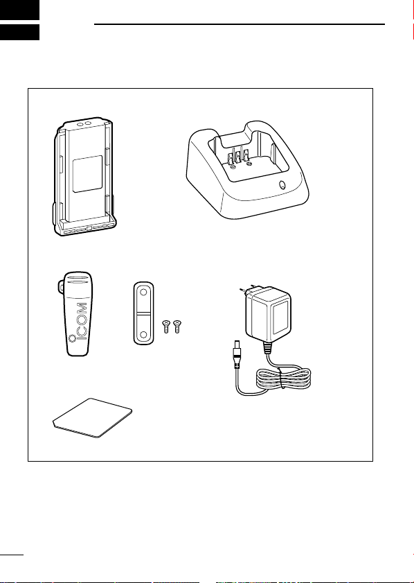
1
Battery pack
Belt clip Jack cover
(with screws)
AC adapter*
1
(for the battery charger)
Battery charger
Unit cover*
2
(double-sided tape)
Depends on version.
Use the unit cover as a spare.
Ask your dealer for details.
*
1
*
2
ACCESSORIES
■ Supplied accessories
1
Page 7
ACCESSORIES
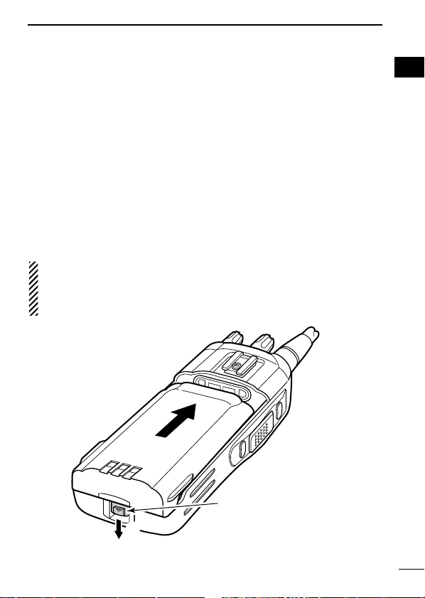
q
w
Battery release button
1
■ Accessory attachments
ï Battery pack
To attach the battery pack:
Slide the battery pack in the direction of the arrow (q), then lock it
with the battery release button.
• Slide the battery pack until the battery release button makes a ‘click’
sound.
To release the battery pack:
Push the battery release button in the direction of the arrow (w).
Then slide the battery pack in the direction opposite to the arrow
(q).
NEVER release or attach the battery pack when the transceiver
is wet or soiled. This may result in water or dust getting into the
transceiver/battery pack and may result in the transceiver being
damaged.
1
2
Page 8
ACCESSORIES
q
w
1
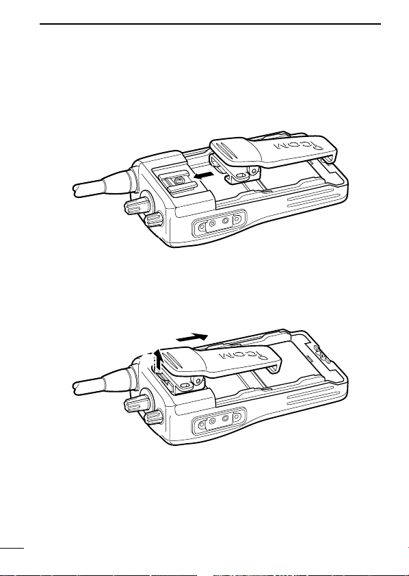
D Belt clip
To attach the belt clip:
q Release the battery pack if it is attached.
w Slide the belt clip in the direction of the arrow until the belt clip is
locked and makes a ‘click’ sound.
To detach the belt clip:
q Release the battery pack if it is attached.
w Pinch to lift the clip (q), and slide the belt clip in the direction of
arrow (w).
3
Page 9
ACCESSORIES
w
q
q
q
w
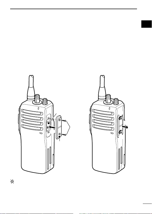
[MIC/SP] jack
Jack cover
ï Jack cover
Attach the jack cover when the optional speaker-microphone or
headset is not used.
1
1
To attach the jack cover:
q Attach the jack cover to the
[MIC/SP] jack.
w Tighten the screws using a
Phillips screwdriver.
CAUTION!: Use the supplied screws only.
To detach the jack cover:
q Unscrew the screws using a
Phillips screwdriver.
w Detach the jack cover for the
optional speaker-microphone
or headset connection.
4
Page 10
2
r
w
y
u
e
Microphone
Speaker
t
Antenna
q
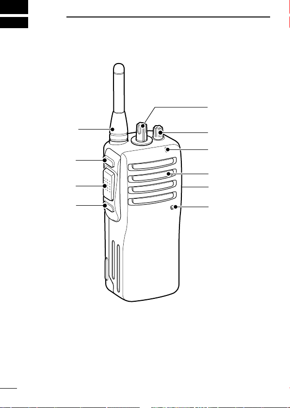
PANEL DESCRIPTION
■ Front, top and side panels
q CHANNEL SELECTOR [CH selector]
Rotate to select the pre-programmed memory channels.
w VOLUME CONTROL [VOL]
Rotate to turn the power ON/OFF and adjust the audio level.
5
Page 11
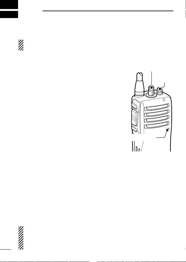
PANEL DESCRIPTION
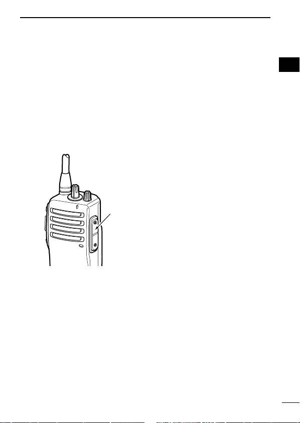
Jack cover
NOTE: Attach the jack cover
when optional equipment is
not used.
See page 4 for details.
2
e LED INDICATOR (p. 7)
➥ Lights red while transmitting.
➥ Lights green while receiving a signal, or when the squelch is
open.
➥ Blinks orange after transmitting/receiving a Smart-Ring call.
➥ Blinks green to indicate the low battery condition.
r EXTERNAL MICROPHONE/SPEAKER JACK [MIC/SP]
Connect an optional speaker-microphone or headset.
t PROGRAMMABLE KEY [Lower]
The desired function can be assigned. (p. 8)
y PTT SWITCH [PTT]
Push and hold to transmit; release to receive.
u PROGRAMMABLE KEY [Upper]
The desired function can be assigned. (p. 8)
2
6
Page 12
PANEL DESCRIPTION
R R R R
O O
G G G G
G G
G
G G
R R
R (O)*
2
‘‘
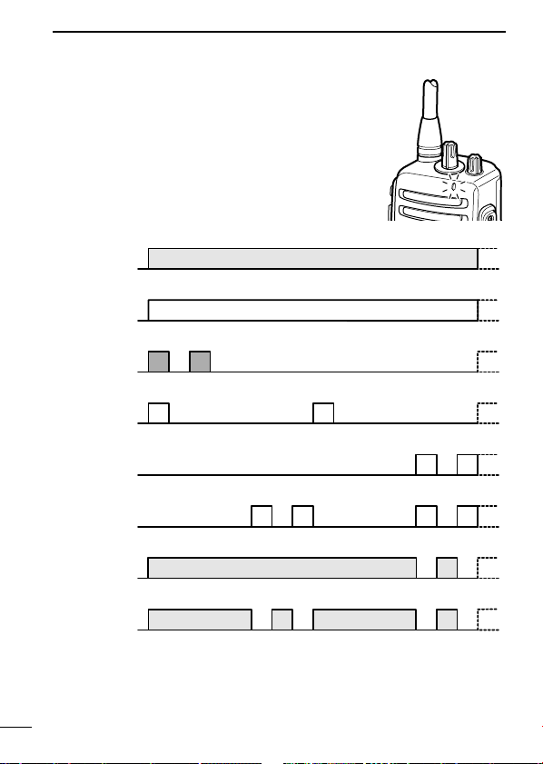
LED indicator
The LED indicator indicates the information as
follows;
(Ref.; R=Red, G=Green, O=Orange)
• TX: Turns Red while transmitting a signal.
• RX: Turns Green while receiving a signal.
• Call LED (Blink): Transmitting or receiving the Smart-Ring.
• Auto/Find scan: Blinks while Auto/Find scan is activated.
• Low BATT1: You should charge the battery. (blinks slowly)
• Low BATT2: You must charge the battery. (blinks fast)
• TX low BATT1: Low BATT1 was detected during TX mode.
• TX low BATT2: Low BATT2 was detected during TX mode.
* During the alkaline battery operation.
7
Page 13

PANEL DESCRIPTION
[Smart Ring/Ringer]
[Moni]
[Scrambler]
[Null]
1 high beep is emitted.
2 high beeps are emitted.
3 high beeps are emitted.
1 high beep is emitted for 1 sec.
‘‘
Programmable function keys
The desired key function can be assigned to [Upper] and [Lower]
in following way.
q Turn power OFF in advance.
w Rotate [CH selector] to select channel 16.
e Rotate [VOL] to turn power ON while pushing and holding the
desired key, [Upper] or [Lower], to be assigned.
• The beep is emitted depending on the selected function as below.
r Turn power OFF.
t Repeat steps e and r until the desired key function is assigned.
NULL KEY
No function.
SMART RING/RINGER KEY
➥ Push to send a Smart-Ring call.
➥ Push and hold for 1 sec. to send a Call-Ring.
MONITOR KEY
➥ Push to mute the CTCSS (or DTCS) squelch mute.
➥ Push and hold for 1 sec. to release the CTCSS (or DTCS)
squelch mute.
➥ Open any squelch/deactivate any mute while pushing and hold-
ing this key.
VOICE SCRAMBLER FUNCTION KEY
➥ Push to turn the voice scrambler function OFF.
➥ Push and hold for 1 sec. to turn the voice scrambler function ON.
2
2
8
Page 14
3
[VOL]
[CH selector]
Microphone
BASIC OPERATION
■ Receiving and transmitting
Prior to using the transceiver for the first time, the battery pack
must be fully charged for optimum life and operation. (P. 24)
Receiving:
q Rotate [VOL] clockwise to turn power
ON.
w Rotate [CH selector] to select the de-
sired operating channel.
• Set your group code number if required.
(pgs. 13–16)
• Scan starts automatically when channel
16 is selected. (p. 11)
e Listen for a transmission and adjust
[VOL] to a comfortable listening level.
• The LED indicator turns green, when
the received signal contains the same
CTCSS tone or DTCS code.
• When no transmission is heard, push
and hold [MONI] while adjusting [VOL].
r The transceiver is now set to receive desired calls on the se-
lected channel.
Transmitting:
Wait for the channel to become clear to avoid interference.
q While pushing and holding [PTT], speak into the microphone at
w Release [PTT] to return to receive.
a normal voice level.
• The LED indicator turns red.
IMPORTANT!: To maximize the readability of your signal;
1. Pause briefly after pushing [PTT].
2. Hold the microphone 5 to 10 cm from your lips, then speak
9
into the microphone at a normal voice level.
Page 15

BASIC OPERATION
Frequency (MHz)*
1
446.006250
446.018750
446.031250
446.043750
446.056250
446.068750
446.081250
446.093750
446.006250
446.018750
446.031250
446.043750
446.056250
446.068750
446.081250
Auto Scan
Tone (Hz)*
2
No setting
No setting
No setting
107.2
110.9
114.8
118.8
123.0
127.3
131.8
136.5
141.3
146.2
151.4
156.7
—
CH
1
2
3
4
5
6
7
8
9
10
11
12
13
14
15
16
DD
Frequency channel/CTCSS tone list (default)
3
3
*1All operating channel frequencies cannot be changed.
*2CTCSS tones can be programmed. You can use DTCS (Digital Tone
Code Squelch) instead of CTCSS. (p. 15)
10
Page 16

BASIC OPERATION
[Upper]
[VOL]
[Lower]
[PTT]
[CH selector]
3
‘‘
Setting the squelch level
The squelch circuit mutes the received audio signal depending on
the signal strength.
q Turn power OFF in advance.
w While pushing and holding [PTT]
and [Lower], rotate [VOL] to
turn power ON to enter the
squelch adjustment mode.
• A beep (Pi) is emitted.
e Push [Upper] to increase the
squelch level (tight squelch) or
[Lower] to decrease the squelch
level (loose squelch).
• Squelch level will be fixed after 1
sec.
r Turn power OFF, then ON again.
‘‘
Auto scan function
Auto scan function proceeds from lower channel to higher channel
numbers in sequence. Scanning searches for signals automatically
and makes it easier to locate new stations for contact or listening
purposes.
q Rotate [CH selector] to select
w Scan starts automatically.
11
channel 16.
• The LED indicator blinks green
slowly.
• When receiving a signal, scan
pauses until the signal disappears.
Page 17

BASIC OPERATION
[VOL]
[PTT]
‘‘
Battery type selection
The battery type MUST be selected according to the type of bat-
tery attached when turning the transceiver ON.
Ask your dealer for details.
NOTE: When the selected battery type is not matched to the attached battery, the transceiver does not work correctly.
q Turn power OFF in advance.
w While pushing and holding [PTT],
rotate [VOL] to turn power ON.
e After the transceiver is powered
ON, you should hold [PTT] for 5
sec. to toggle the attached battery
type.
• When the Lithium-Ion battery type is
selected, a beep (Pi) is emitted after
a 5 sec. count.
• When the Alkaline battery type is
selected, 2 beeps (PiPi) are emitted
after a 5 sec. count.
In this case, the LED indicator turns
orange while transmitting a signal.
3
3
12
Page 18

BASIC OPERATION
3
‘‘
Setting the group code number
DD
CTCSS tone setting
The transceiver is equipped with 50 CTCSS tones and OFF. CTCSS
operation provides communication with silent standby since you will
only receive calls from group members using the same CTCSS tone.
q Turn power OFF in advance.
w While pushing and holding [PTT], [Upper] and [Lower], rotate
[VOL] to turn the power ON.
e Rotate [CH selector] to select the desired channel (1 to 15) that
you want to assign the CTCSS tone to.
r Push and hold [Upper] until a long beep is emitted.
t Push [PTT] the necessary number of times to choose the 10
digit of the desired CTCSS tone number (grey column) from the
list at right.
y Push [Upper].
• Confirmation beep(s) is (are) emitted. (See the Confirmation beep
list at right.)
u Push [PTT] the necessary number of times to choose the 1 digit
of the desired CTCSS tone number (grey column) from the list at
right.
i Push [Upper] to complete the setting.
• Confirmation beep(s) is (are) emitted. (See the Confirmation beep
list at right.)
o Turn power OFF, then ON again.
[Example]: Tone No. 28 (162.2 Hz) assignment to channel 4
q Turn power OFF in advance.
w While pushing and holding [PTT], [Upper] and [Lower], rotate
[VOL] to turn the power ON.
e Rotate [CH selector] to select channel 4, then push and hold
[Upper] until a long beep is emitted.
13
Page 19

BASIC OPERATION
3
r Push [PTT] twice to choose the 2 (10 digit) of the tone number
28.
t Push [Upper] (
2 short beeps are emitted,) then push [PTT] eight
times to choose the 8 (1 digit) of the tone number 28.
y Push [Upper] to complete the setting.
• A long beep and 3 short beeps are emitted.
u Turn power OFF, then ON again.
• Available CTCSS tone list (Hz)
Freq.
No.
01
02
03
04
05
06
07
08
09
10
67.0
69.3
71.9
74.4
77.0
79.7
82.5
85.4
88.5
91.5
No.
11
12
13
14
15
16
17
18
19
20
Freq.
94.8
97.4
100.0
103.5
107.2
110.9
114.8
118.8
123.0
127.3
No.
21
22
23
24
25
26
27
28
29
30
Freq.
131.8
136.5
141.3
146.2
151.4
156.7
159.8
162.2
165.5
167.9
No.
31
32
33
34
35
36
37
38
39
40
Freq.
171.3
173.8
177.3
179.9
183.5
186.2
189.9
192.8
196.6
199.5
No.
41
42
43
44
45
46
47
48
49
50
00
Freq.
203.5
206.5
210.7
218.1
225.7
229.1
233.6
241.8
250.3
254.1
OFF
• Confirmation beep list
Push [PTT] Confirmation beep
No push
1 (Once)
2 (Twice)
3 (Third)
4 (Fourth)
●
●
●●
●●●
●●●●
Push [PTT] Confirmation beep
5 (Fifth)
6 (Sixth)
7 (Seventh)
8 (Eighth)
9 (Ninth)
●●●●●
●
●●
●●●
●●●●
3
● : Short beep : Long beep
14
Page 20

BASIC OPERATION
3
DD
DTCS code setting
This transceiver is equipped with 84 DTCS codes and OFF.
DTCS operation provides communication with silent standby since
you will only receive calls from group members using the same
DTCS code.
q Turn power OFF in advance.
w While pushing and holding [PTT], [Upper] and [Lower], rotate
[VOL] to turn the power ON.
e Rotate [CH selector] to select the desired channel (1 to 15) that
you want to assign the DTCS code to.
r Push and hold [Lower] until a long beep is emitted.
t Push [PTT] the necessary number of times to choose the 10
digit of the desired DTCS code number (grey column) from the
list at right.
y Push [Upper].
• Confirmation beep(s) is (are) emitted. (See the Confirmation beep
list on p. 14.)
u Push [PTT] the necessary number of times to choose the 1 digit
of the desired DTCS code number (grey column) from the list at
right.
i Push [Upper].
• Confirmation beep(s) is (are) emitted. (See the Confirmation beep
list on p. 14.)
o If you want to use Inverse mode, push [PTT] once more.
*You can skip this step, if you want to use Normal mode.
!0 Push [Upper] to complete the setting.
• A short beep is emitted.
!1 Turn power OFF, then ON again.
[Example]: Code No. 16 (114) with Inverse mode assignment to
channel 5
q Turn power OFF in advance.
w While pushing and holding [PTT], [Upper] and [Lower], rotate
15
[VOL] to turn the power ON.
Page 21

BASIC OPERATION
371
411
412
413
423
431
432
445
464
465
51
52
53
54
55
56
57
58
59
60
466
503
506
516
532
546
565
606
612
624
61
62
63
64
65
66
67
68
69
70
627
631
632
654
662
664
703
712
723
731
71
72
73
74
75
76
77
78
79
80
732
734
743
754
OFF
81
82
83
84
00
Code
023
025
026
031
032
036
043
047
051
054
No.
01
02
03
04
05
06
07
08
09
10
Code
065
071
072
073
074
114
115
116
125
131
No.
11
12
13
14
15
16
17
18
19
20
Code
132
134
143
152
155
156
162
165
172
174
No.
21
22
23
24
25
26
27
28
29
30
Code
205
223
226
243
244
245
251
261
263
265
No.
31
32
33
34
35
36
37
38
39
40
Code
271
306
311
315
331
343
346
351
364
365
No.
41
42
43
44
45
46
47
48
49
50
e Rotate [CH selector] to select channel 5, then push and hold
[Lower] until a long beep is emitted.
r Push [PTT] once to choose the 1 (10 digit) of the code number 16.
t Push [Upper] (
a short beep is emitted,) then push [PTT] six times
to choose the 6 (1 digit) of the code number 16.
y Push [Upper].
• A long beep and a short beep are emitted.
u Push [PTT] once more, to use Inverse mode.
i Push [Upper] to complete the setting.
• A short beep is emitted.
o Turn the power OFF, and then ON again.
• Available DTCS code list
3
3
16
Page 22

BASIC OPERATION
3
‘‘
Find scan operation
This transceiver can detect the CTCSS tone and DTCS code* in
the received signal. By monitoring a signal that is being transmitted from the other station, you can determine the tone frequency or
DTCS code* required to communicate with them.
This function is very useful when you are going to communicate
with unknown CTCSS tone or DTCS code* stations.
Scans all of the CTCSS tone and DTCS code*, then stops when a
matched tone or code* is detected.
q Turn power OFF in advance.
w While pushing and holding [Upper] and [Lower], rotate [VOL] to
turn power ON.
Do not select channel 16 before turning power ON.
e Rotate [CH selector] to select the desired channel (1 to 15) that
you want to assign the CTCSS tone or DTCS code* to.
r Push and hold [Upper] for 1 sec. to start scan.
• The LED indicator blinks green slowly.
• Push [Upper] to stop the scan.
t The scan pauses when the matched tone or code* is detected.
• Push [Upper] to determine the detected tone or code* number, and
stop the scan.
• Scan resumes 3 sec. after the signal disappears.
y Turn power OFF, then ON again.
Even if the scan is stopped with pushing [Upper], scan resumes
after pushing and holding [Upper].
* Depends on the pre-setting.
17
Page 23

RINGER FUNCTION
[Upper]
[VOL]
[PTT]
[CH selector]
‘‘
Call-Ring operation
Sends the pre-selected ring tone to your group members.
DD
Select the Call-Ring melody
q Turn power OFF in advance.
w While pushing and holding [PTT]
and [Upper], rotate [VOL] to
turn power ON.
• A sample melody is emitted.
e Rotate [CH selector] to select
the ringer melody.
r Turn power OFF to determine
the melody.
DD
Call your group member with Call-Ring melody
q Set the same operating channel and CTCSS tone for all of your
group transceivers. (p. 13)
w Pushing and holding [Smart Ring/Ringer] for 1 sec. to send the
pre-selected ring tone to your group member.
• The ring tone is emitted while [Smart Ring/Ringer] is pushed and
held.
• The same ring tone comes from your group station’s speaker.
4
3
4
18
Page 24

RINGER FUNCTION
4
‘‘
Smart-Ring operation
The ring function has an answer back feature. This allows you to
confirm whether or not a call has reached to the member of your
group even if the operator is temporarily away from the transceiver.
DD
Smart-Ring operation
q Set the same operating channel and CTCSS tone code for all of
your group transceivers. (p. 13)
w Push [Smart Ring/Ringer] to send the Smart-Ring call.
• When a member of your group station answers your call, the transceiver emits beep tones for every 10 sec.* and the LED indicator
blinks with an orange color.
*Depends on the pre-setting.
• Push [MONI] to cancel the Ringer beep and the LED blinking.
• When no answer comes back, the transceiver emits short failure
beep tones.
e Push [PTT] to answer the call and to stop the beeps and blink-
ing.
NOTE: This function is available only when the called station
has use the same CTCSS tone code and the same operating channels as you.
19
Page 25

RINGER FUNCTION
Push [Smart Ring/Ringer]
Piro Piro
Answer back (automatic)
Piro Piro
Communication
4
4
20
Page 26

5
Only signals containing the proper
tone are received.
All signals are
received
‘‘
The monitor function allows you to open the transceiver’s squelch
manually to check whether a channel is busy or not. The transceiver has 2 conditions for receive standby.
• Audible condition
• Inaudible condition
OTHER FUNCTIONS
Monitor audible function
This condition mutes audio ONLY when no
carrier is present. You can receive (or monitor) any signals on a channel.
• Push and hold [MONI] to release the CTCSS
or DTCS tone squelch mute.
Any received audio is emitted while pushing
and holding [MONI].
This condition mutes ALL signals except
those directed to you. Therefore you should
check a channel’s condition (busy or not)
with the monitor function before transmitting.
• Push [MONI] to mute the CTCSS or DTCS
tone squelch mute.
‘‘
Time-Out Timer
The transceiver has a time-out timer function. This function prevents continuous, extend transmissions. This timer automatically
turns a transmission OFF 3 min. after it starts.
21
Page 27

OTHER FUNCTIONS
‘‘
Power save function
The power save function reduces the current drain to conserve battery power.
• The power save function is automatically turned ON when no operation is performed or no signal is received for 5 sec.
5
‘‘
Low battery indication
The LED indicator indicates 4 levels of the “Low battery” condition
as follows.
If the “Low battery” warning occurs during operation, please charge
or replace the battery.
[Blink patterns]
• Low BATT1: You should charge the battery. (blinks slowly)
G G
• Low BATT2: You must charge the battery. (blinks fast)
G G G G
• TX low BATT1: Low BATT1 was detected during TX mode.
R
• TX low BATT2: Low BATT2 was detected during TX mode.
R R R R
In an extreme low temperature surroundings (around –20°C), the
capacity of the battery may exhaust quickly (especially Alkaline
batteries). In such a case, we recommend to charge the battery
or replace the batteries, when the “Low Battery” indication occurs
during operation.
R
5
22
Page 28

OTHER FUNCTIONS
5
■ Scrambler function
The voice scrambler function provides private communication between stations. The optional UT-110 (Rolling) or UT-109 (Nonrolling) is required. Ask your dealer for details.
q Push and hold [Scrambler] for 1 sec, to turn the scrambler func-
tion ON.
• A short beep and a long beep are emitted.
w Push [Scrambler] to turn the scrambler function OFF.
• A short beep is emitted.
■ All reset function
Reset the CPU before operating the transceiver for the first time,
or if the internal CPU malfunctions, to clear and return all programmed contents to their default settings.
q Turn power OFF in advance.
w Rotate [CH selector] to select channel 16.
e While pushing and holding [PTT], [Upper] and [Lower], rotate
[VOL] to turn power ON.
r After the transceiver is powered ON, you should hold [PTT]
[Upper] and [Lower] for 5 sec. to reset the CPU.
• A long beep is emitted.
t Turn power OFF.
,
23
CAUTION: Resetting the CPU returns all programmed contents
to their default settings.
Page 29

BATTERY CHARGING
6
■ Caution
Misuse of Lithium-Ion batteries may result in the following
hazards: smoke, fire, or the battery may rupture. Misuse can
also cause damage to the battery or degradation of battery
performance.
R DANGER! Use and charge only specified Icom battery packs
with Icom radios or Icom charger. Only Icom battery packs are
tested and approved for use and charge with Icom radios or Icom
charger. Using third-party or counterfeit battery packs or charger
may cause smoke, fire, or cause the battery to burst.
DD
Battery caution
R DANGER! DO NOT hammer or otherwise impact the battery. Do
not use the battery if it has been severely impacted or dropped, or if
the battery has been subjected to heavy pressure. Battery damage
may not be visible on the outside of the case. Even if the surface of
the battery does not show cracks or any other damage, the cells inside the battery may rupture or catch fire.
R DANGER! NEVER use or leave battery packs in areas with tem-
peratures above +60˚C. High temperature buildup in the battery,
such as could occur near fires or stoves, inside a sun heated car, or
in direct sunlight may cause the battery to rupture or catch fire. Excessive temperatures may also degrade battery performance or
shorten battery life.
R DANGER! DO NOT expose the battery to rain, snow, seawater,
or any other liquids. Do not charge or use a wet battery. If the battery gets wet, be sure to wipe it dry before using. The battery is not
waterproof.
R DANGER! NEVER incinerate used battery packs since internal
battery gas may cause them to rupture, or may cause an explosion.
5
6
24
Page 30

BATTERY CHARGING
6
R DANGER! NEVER solder the battery terminals or NEVER mod-
ify the battery pack. This may cause heat generation, and the battery may rupture, emit smoke or catch fire.
R DANGER! Use the battery only with the transceiver for which it
is specified. Never use a battery with any other equipment, or for
any purpose that is not specified in this instruction manual.
R DANGER! If fluid from inside the battery gets in your eyes, blind-
ness can result. Rinse your eyes with clean water, without rubbing
them, and see a doctor immediately.
WARNING! Immediately stop using the battery if it emits an abnormal odor, heats up, or is discolored or deformed. If any of these
conditions occur, contact your Icom dealer or distributor.
WARNING! Immediately wash, using clean water, any part of the
body that comes into contact with fluid from inside the battery.
WARNING! NEVER put the battery in a microwave oven, highpressure container, or in an induction heating cooker. This could
cause a fire, overheating, or cause the battery to rupture.
CAUTION! Always use the battery within the specified temperature
range for the transceiver (–25˚C to +55˚C) and the battery itself
(–20˚C to +60˚C). Using the battery out of its specified temperature
range will reduce the battery’s performance and battery life. Please
note that the specified temperature range of the battery may exceed that of the transceiver. In such cases, the transceiver may not
work properly because it is out of its operating temperature range.
CAUTION! Shorter battery life could occur if the battery is left fully
charged, completely discharged, or in an excessive temperature
environment (above +45˚C) for an extended period of time. If the
battery must be left unused for a long time, it must be detached
from the radio after discharging. You may use the battery until the
remaining capacity is about half, then keep it safely in a cool dry
place with the temperature between –20˚C to +25˚C.
25
Page 31

BATTERY CHARGING
DD
Charging caution
R DANGER! NEVER charge the battery pack in areas with ex-
tremely high temperatures, such as near fires or stoves, inside a
sun heated car, or in direct sunlight. In such environments, the
safety/protection circuit in the battery will activate, causing the battery to stop charging.
WARNING! DO NOT charge or leave the battery in the battery
charger beyond the specified time for charging. If the battery is not
completely charged by the specified time, stop charging and remove the battery from the battery charger. Continuing to charge the
battery beyond the specified time limit may cause a fire, overheating, or the battery may rupture.
WARNING! NEVER insert the transceiver (battery attached to the
transceiver) into the charger if it is wet or soiled. This could corrode
the battery charger terminals or damage the charger. The charger is
not waterproof.
CAUTION! DO NOT charge the battery outside of the specified
temperature range: BC-160 and BC-171 (0˚C to +45˚C). Icom recommends charging the battery at +20˚C. The battery may heat up
or rupture if charged out of the specified temperature range. Additionally, battery performance or battery life may be reduced.
6
6
26
Page 32

BATTERY CHARGING
AC adapter
(Not supplied with
some versions.)
Optional OPC-515L
(for 13.8 V power
source) or CP-17L
(for 12 V cigarette
lighter socket) can
be used instead of
the AC adapter.
Battery pack
Transceiver
Turn power OFF
6
■ Battery chargers
D Rapid charging with the BC-160
The BC-160 provides rapid charging of the optional Li-Ion battery
pack. Charging period: Approx. 3 hours (with BP-232N)
The following items are additionally required:
• An AC adapter (may be supplied depending on version) or the DC
power cable (OPC-515L/CP-17L) is additionally required.
27
Page 33

BATTERY CHARGING
AC adapter
(Not supplied with
some versions.)
Optional OPC-515L
(for 13.8 V power
source) or CP-17L
(for 12 V cigarette
lighter socket) can
be used instead of
the AC adapter.
Battery pack
Transceiver
Turn power OFF
D Regular charging with the BC-171
The BC-171 provides regular charging of the optional Li-Ion battery
pack. Charging period: Approx. 10 hours (with BP-232N)
The following items are additionally required:
• An AC adapter (may be supplied depending on version) or the DC
power cable (OPC-515L/CP-17L) is additionally required.
6
6
28
Page 34

BATTERY CHARGING
Screws are supplied with the
charger adapter.
AD-106
Connectors
Plugs
6
ï AD-106 installation
q Install the AD-106 desktop charger adapter into the holder space
of the BC-119N/BC-121N.
w Connect the plugs of the BC-119N/BC-121N to the AD-106 with
the connector, then install the adapter into the charger with the
supplied screws.
29
Page 35

BATTERY CHARGING
The AD-106
charger adapter
is installed in the
BC-119N.
AC adapter
(Not supplied with
some versions.)
Optional OPC-515L
(for 13.8 V power
source) or CP-17L
(for 12 V cigarette
lighter socket) can
be used instead of
the AC adapter.
Battery pack
Transceiver
Turn power OFF
D Rapid charging with the BC-119N+AD-106
The optional BC-119N provides rapid charging of the Li-Ion battery
packs. Charging period: Approx. 3 hours (with BP-232N)
The following items are additionally required:
• An AD-106 charger adapter
• An AC adapter (may be supplied with the BC-119N depending on
version) or the DC power cable (OPC-515L/CP-17L).
6
6
30
Page 36

BATTERY CHARGING
AC adapter
(Purchased
separately)
AD-106 charger
adapters are installed
in each slot.
DC power cable
(OPC-656)
(Connect with the
DC power supply;
13.8 V/at least 7 A)
Battery pack
Transceiver
Turn power OFF
6
D Rapid charging with the BC-121N+AD-106
The optional BC-121N allows up to 6 battery packs to be charged
simultaneously. Charging period: Approx. 3 hours (with BP-232N)
The following items are additionally required.
• Six AD-106 charger adapters
• An AC adapter (BC-157) or the DC power cable (OPC-656)
31
Page 37

BATTERY CHARGING
Guide rail
Lobs
IMPORTANT!: Battery charging caution
Ensure the guide lobs on the battery pack are correctly
aligned with the guide rails inside the charger adapter. (This
illustration is shown using the BC-160.)
6
6
32
Page 38

7
BATTERY CASE
■ Optional battery case (BP-240)
When using the optional battery case, install 6 × AAA (LR03) size
alkaline batteries as illustrated at right.
q Unhook the battery cover release hook (q), and open the cover
in the direction of the arrow (w). (Fig.1)
w Then, install 6 × AAA (LR03) size alkaline batteries. (Fig.2)
• Install the alkaline batteries only.
• Be sure to observe the correct polarity.
• Do not pin the ribbon under the batteries.
e Fit the cover in the direction of the arrow (e), then close (r).
Hook the battery cover release hook until it makes a ‘click’ sound
(t). (Fig.3)
CAUTION:
• When installing batteries, make sure they are all the same
brand, type and capacity. Also, do not mix new and old batteries together.
• Keep battery contacts clean. It’s a good idea to clean battery
terminals once a week.
• Never incinerate used battery cells since internal battery gas
may cause them to rupture.
• Never expose a detached battery case to water. If the battery
case gets wet, be sure to wipe it dry before using it.
NOTE: When the optional battery case is attached, the battery
type must be selected to “Alkaline battery operation” when turning the transceiver ON. (p. 12)
33
Page 39

BATTERY CASE
q
BP-240
w
Fig.1
Fig.2
Fig.3
e
r
t
7
7
34
Page 40

8
q w
SWIVEL BELT CLIP
■ MB-93 contents
Qty.
q Belt clip …………………………………………………………… 1
w Base clip …………………………………………………………… 1
■ Attaching
q Release the battery pack if it is attached. (p. 2)
w Slide the base clip in the direction of the arrow until the base clip
is locked and makes a ‘click’ sound.
35
Page 41

SWIVEL BELT CLIP
Once the transceiver is locked in place,
it will swivel 360 degrees.
e Clip the belt clip to a part of your belt. And insert the transceiver
into the belt clip until the base clip is inserted fully into the groove.
r Once the transceiver is locked in place, it swivels as illustrated
below.
8
8
36
Page 42

SWIVEL BELT CLIP
8
■ Detaching
q Turn the transceiver upside down in the direction of the arrow
and pull out from the belt clip.
37
Page 43

SWIVEL BELT CLIP
q
w
w Release the battery pack if it is attached. (p. 2)
e Pinch to lift the clip (q), and slide the base clip in the direction of
the arrow (w).
CAUTION:
HOLD THE TRANSCEIVER TIGHTLY, WHEN HANGING OR
DETACHING THE TRANSCEIVER FROM THE BELT CLIP.
Otherwise the transceiver may not be attached to the holder or
swivel properly if the transceiver is accidentally dropped and the
base clip is scratched or damaged.
8
8
38
Page 44

9
7.4 V
7.4 V
Battery case for AAA
(LR03) × 6 alkaline
13 hrs.
26.5 hrs.
980 mAh
2000 mAh
Battery pack
BP-230N
BP-232N
BP-240
Voltage Capacity Battery life*
1
*1 When the power save function is turned ON, and the operating
periods are calculated under the following conditions;
TX : RX : Standby = 5 : 5 : 90
*
2
Operating period depends on the alkaline cells used.
—*
2
OPTIONS
D BATTERY PACKS
D CHARGERS
• BC-119N
+ BC-145
For rapid charging of battery pack. An AC adapter is supplied with
the charger depending on versions.
Charging time: Approx. 3 hours when BP-232N is attached.
• BC-121N
+ BC-157
For rapid charging of up to 6 battery packs (six AD-106’s are required) simultaneously. An AC adapter should be purchased separately.
Charging time: Approx. 3 hours when BP-232N is attached.
• BC-160
For rapid charging of battery packs. An AC adapter is supplied
with the charger depending on versions.
Charging time: Approx. 3 hours when BP-232N is attached.
• BC-171
For regular charging of battery packs. We recommend that the
BP-230N charging. An AC adapter is supplied with the charger depending on versions.
Charging time: Approx. 10 hours when BP-232N is attached.
39
DESKTOP CHARGER
AC ADAPTER
-
CHARGER
MULTI
AC ADAPTER
DESKTOP CHARGER
DESKTOP CHARGER
+ AD-106
+ BC-145
+ BC-147
+ AD-106
CHARGER ADAPTER
CHARGER ADAPTER
AC ADAPTER
AC ADAPTER
Approx. 4 hours when BP-230N is attached.
(6 pcs.)
Page 45

OPTIONS
D OPTIONAL UNITS
• UT-109 (#01)/UT-110 (#01)
Non-rolling type (UT-109)/Rolling type (UT-110) voice scrambler
unit provides higher communication security.
SCRAMBLER UNITS
D BELT CLIPS
• MB-93
• MB-94
• MB-96N/96F
SWIVEL BELT CLIP
BELT CLIP
Exclusive alligator-type belt clip.
LEATHER BELT HANGER
D DC CABLES
• CP-17L
Allows charging of the battery pack through a 12 V cigarette
lighter socket. (For BC-119N)
• OPC-515L/OPC-656
Allows charging of the battery pack using a 13.8 V power source
instead of the AC adapter.
OPC-515L : For BC-119N
OPC-656 : For BC-121N
CIGARETTE LIGHTER CABLE
DC POWER CABLES
D OTHER OPTIONS
• SP-13
• HM-153L
• HM-158L/159L
• HS-94/HS-95/HS-97
EARPHONE
Provides clear receive audio in noisy environments.
EARPHONE-MICROPHONE
SPEAKER
MICROPHONE
Combination speaker-microphone that provides convenient operation while hanging the transceiver from your belt.
HEADSET
+ VS-1L
VOX/PTT CASE
HS-94 : Ear hook type HS-95: Neck-arm type
HS-97 : Throat microphone
VS-1L : VOX/PTT switch box for hands-free operation, etc.
9
9
Some options may not be available in some countries. Please ask your
dealer for details.
40
Page 46

10
DD
• Frequency coverage : 446.00625–446.09375 MHz
• Mode : 8K50F3E (FM)
• Current drain (at 7.2 V) : TX (at 0.5 W ERP) 0.4 A approx.
• Power supply requirement : 7.2 V DC nominal*
• Frequency stability : ±2.5 ppm
• Antenna impedance : 50 Ω nominal
• Dimensions : 53.0(W) × 195.0(H) × 38.0(D) mm
• Weight : Approx. 300 g (including BP-232N)
DD
• Output power : 0.5 W ERP
• Modulation system : Variable reactance frequency
• Max. frequency deviation : ±2.5 kHz
• Spurious emissions : 0.25 µW below 1 GHz
• Adjacent channel power : 60 dB
• External mic. connector : 3-conductor 2.5 (d) mm/2.2 kΩ
SPECIFICATIONS
General
Max. audio 300 mA max.
(negative ground)
*Specified Icom’s battery pack only
(–25°C to +55°C)
(Fixed type antenna included)
Transmitter
modulation
1.00 µW above 1 GHz
41
Page 47

SPECIFICATIONS
DD
Receiver
• Receive system : Double conversion
superheterodyne
• Sensitivity (20 dB SINAD) : 26.5 dBµV/m
• Squelch sensitivity : 26.5 dBµV/m (Threshold)
• Intermodulation rejection ratio : 86.29 dBµV/m
• Spurious response rejection ratio : 91.29 dBµV/m
• Adjacent channel selectivity : 81.29 dBµV/m
• Audio output power : 0.5 W (typical) at 5% distor-
tion with an 8 Ω load
0.6 W (typical) at 5% distor-
tion with a 6 Ω load
• External speaker connector : 2-conductor 3.5 (d) mm/8 Ω
10
All stated specifications are subject to change without notice
or obligation.
10
42
Page 48

< Intended Country of Use >
GER
AUT
GBR
IRL
NOR
FRA
NED
BEL
LUX
ESP
POR
ITA
GRE
SWE
DEN
FIN
SUI
A-6540D-1EU
Printed in Japan
© 2006 Icom Inc.
1-1-32 Kamiminami, Hirano-ku, Osaka 547-0003, Japan
 Loading...